EP3579954B1 - Modified siloxane composite membranes for heavy hydrocarbon recovery - Google Patents
Modified siloxane composite membranes for heavy hydrocarbon recovery Download PDFInfo
- Publication number
- EP3579954B1 EP3579954B1 EP18707463.8A EP18707463A EP3579954B1 EP 3579954 B1 EP3579954 B1 EP 3579954B1 EP 18707463 A EP18707463 A EP 18707463A EP 3579954 B1 EP3579954 B1 EP 3579954B1
- Authority
- EP
- European Patent Office
- Prior art keywords
- composite membrane
- formula
- polymer material
- copolymer
- polymer
- Prior art date
- Legal status (The legal status is an assumption and is not a legal conclusion. Google has not performed a legal analysis and makes no representation as to the accuracy of the status listed.)
- Active
Links
- 0 CCC(CC)N(C)* Chemical compound CCC(CC)N(C)* 0.000 description 1
Images











Classifications
-
- B—PERFORMING OPERATIONS; TRANSPORTING
- B01—PHYSICAL OR CHEMICAL PROCESSES OR APPARATUS IN GENERAL
- B01D—SEPARATION
- B01D53/00—Separation of gases or vapours; Recovering vapours of volatile solvents from gases; Chemical or biological purification of waste gases, e.g. engine exhaust gases, smoke, fumes, flue gases, aerosols
- B01D53/22—Separation of gases or vapours; Recovering vapours of volatile solvents from gases; Chemical or biological purification of waste gases, e.g. engine exhaust gases, smoke, fumes, flue gases, aerosols by diffusion
- B01D53/228—Separation of gases or vapours; Recovering vapours of volatile solvents from gases; Chemical or biological purification of waste gases, e.g. engine exhaust gases, smoke, fumes, flue gases, aerosols by diffusion characterised by specific membranes
-
- B—PERFORMING OPERATIONS; TRANSPORTING
- B01—PHYSICAL OR CHEMICAL PROCESSES OR APPARATUS IN GENERAL
- B01D—SEPARATION
- B01D67/00—Processes specially adapted for manufacturing semi-permeable membranes for separation processes or apparatus
- B01D67/0002—Organic membrane manufacture
- B01D67/0009—Organic membrane manufacture by phase separation, sol-gel transition, evaporation or solvent quenching
- B01D67/0013—Casting processes
-
- B—PERFORMING OPERATIONS; TRANSPORTING
- B01—PHYSICAL OR CHEMICAL PROCESSES OR APPARATUS IN GENERAL
- B01D—SEPARATION
- B01D67/00—Processes specially adapted for manufacturing semi-permeable membranes for separation processes or apparatus
- B01D67/0081—After-treatment of organic or inorganic membranes
- B01D67/0088—Physical treatment with compounds, e.g. swelling, coating or impregnation
-
- B—PERFORMING OPERATIONS; TRANSPORTING
- B01—PHYSICAL OR CHEMICAL PROCESSES OR APPARATUS IN GENERAL
- B01D—SEPARATION
- B01D69/00—Semi-permeable membranes for separation processes or apparatus characterised by their form, structure or properties; Manufacturing processes specially adapted therefor
- B01D69/02—Semi-permeable membranes for separation processes or apparatus characterised by their form, structure or properties; Manufacturing processes specially adapted therefor characterised by their properties
-
- B—PERFORMING OPERATIONS; TRANSPORTING
- B01—PHYSICAL OR CHEMICAL PROCESSES OR APPARATUS IN GENERAL
- B01D—SEPARATION
- B01D69/00—Semi-permeable membranes for separation processes or apparatus characterised by their form, structure or properties; Manufacturing processes specially adapted therefor
- B01D69/10—Supported membranes; Membrane supports
- B01D69/107—Organic support material
-
- B—PERFORMING OPERATIONS; TRANSPORTING
- B01—PHYSICAL OR CHEMICAL PROCESSES OR APPARATUS IN GENERAL
- B01D—SEPARATION
- B01D69/00—Semi-permeable membranes for separation processes or apparatus characterised by their form, structure or properties; Manufacturing processes specially adapted therefor
- B01D69/10—Supported membranes; Membrane supports
- B01D69/107—Organic support material
- B01D69/1071—Woven, non-woven or net mesh
-
- B—PERFORMING OPERATIONS; TRANSPORTING
- B01—PHYSICAL OR CHEMICAL PROCESSES OR APPARATUS IN GENERAL
- B01D—SEPARATION
- B01D69/00—Semi-permeable membranes for separation processes or apparatus characterised by their form, structure or properties; Manufacturing processes specially adapted therefor
- B01D69/12—Composite membranes; Ultra-thin membranes
- B01D69/1214—Chemically bonded layers, e.g. cross-linking
-
- B—PERFORMING OPERATIONS; TRANSPORTING
- B01—PHYSICAL OR CHEMICAL PROCESSES OR APPARATUS IN GENERAL
- B01D—SEPARATION
- B01D69/00—Semi-permeable membranes for separation processes or apparatus characterised by their form, structure or properties; Manufacturing processes specially adapted therefor
- B01D69/12—Composite membranes; Ultra-thin membranes
- B01D69/1216—Three or more layers
-
- B—PERFORMING OPERATIONS; TRANSPORTING
- B01—PHYSICAL OR CHEMICAL PROCESSES OR APPARATUS IN GENERAL
- B01D—SEPARATION
- B01D69/00—Semi-permeable membranes for separation processes or apparatus characterised by their form, structure or properties; Manufacturing processes specially adapted therefor
- B01D69/12—Composite membranes; Ultra-thin membranes
- B01D69/125—In situ manufacturing by polymerisation, polycondensation, cross-linking or chemical reaction
-
- B—PERFORMING OPERATIONS; TRANSPORTING
- B01—PHYSICAL OR CHEMICAL PROCESSES OR APPARATUS IN GENERAL
- B01D—SEPARATION
- B01D69/00—Semi-permeable membranes for separation processes or apparatus characterised by their form, structure or properties; Manufacturing processes specially adapted therefor
- B01D69/12—Composite membranes; Ultra-thin membranes
- B01D69/125—In situ manufacturing by polymerisation, polycondensation, cross-linking or chemical reaction
- B01D69/1251—In situ manufacturing by polymerisation, polycondensation, cross-linking or chemical reaction by interfacial polymerisation
-
- B—PERFORMING OPERATIONS; TRANSPORTING
- B01—PHYSICAL OR CHEMICAL PROCESSES OR APPARATUS IN GENERAL
- B01D—SEPARATION
- B01D71/00—Semi-permeable membranes for separation processes or apparatus characterised by the material; Manufacturing processes specially adapted therefor
- B01D71/06—Organic material
- B01D71/70—Polymers having silicon in the main chain, with or without sulfur, nitrogen, oxygen or carbon only
- B01D71/701—Polydimethylsiloxane
-
- C—CHEMISTRY; METALLURGY
- C10—PETROLEUM, GAS OR COKE INDUSTRIES; TECHNICAL GASES CONTAINING CARBON MONOXIDE; FUELS; LUBRICANTS; PEAT
- C10L—FUELS NOT OTHERWISE PROVIDED FOR; NATURAL GAS; SYNTHETIC NATURAL GAS OBTAINED BY PROCESSES NOT COVERED BY SUBCLASSES C10G OR C10K; LIQUIFIED PETROLEUM GAS; USE OF ADDITIVES TO FUELS OR FIRES; FIRE-LIGHTERS
- C10L3/00—Gaseous fuels; Natural gas; Synthetic natural gas obtained by processes not covered by subclass C10G, C10K; Liquefied petroleum gas
- C10L3/06—Natural gas; Synthetic natural gas obtained by processes not covered by C10G, C10K3/02 or C10K3/04
- C10L3/10—Working-up natural gas or synthetic natural gas
- C10L3/101—Removal of contaminants
-
- B—PERFORMING OPERATIONS; TRANSPORTING
- B01—PHYSICAL OR CHEMICAL PROCESSES OR APPARATUS IN GENERAL
- B01D—SEPARATION
- B01D53/00—Separation of gases or vapours; Recovering vapours of volatile solvents from gases; Chemical or biological purification of waste gases, e.g. engine exhaust gases, smoke, fumes, flue gases, aerosols
- B01D53/22—Separation of gases or vapours; Recovering vapours of volatile solvents from gases; Chemical or biological purification of waste gases, e.g. engine exhaust gases, smoke, fumes, flue gases, aerosols by diffusion
- B01D2053/221—Devices
-
- B—PERFORMING OPERATIONS; TRANSPORTING
- B01—PHYSICAL OR CHEMICAL PROCESSES OR APPARATUS IN GENERAL
- B01D—SEPARATION
- B01D2256/00—Main component in the product gas stream after treatment
- B01D2256/24—Hydrocarbons
- B01D2256/245—Methane
-
- B—PERFORMING OPERATIONS; TRANSPORTING
- B01—PHYSICAL OR CHEMICAL PROCESSES OR APPARATUS IN GENERAL
- B01D—SEPARATION
- B01D2257/00—Components to be removed
- B01D2257/70—Organic compounds not provided for in groups B01D2257/00 - B01D2257/602
- B01D2257/702—Hydrocarbons
-
- B—PERFORMING OPERATIONS; TRANSPORTING
- B01—PHYSICAL OR CHEMICAL PROCESSES OR APPARATUS IN GENERAL
- B01D—SEPARATION
- B01D2311/00—Details relating to membrane separation process operations and control
- B01D2311/10—Temperature control
-
- B—PERFORMING OPERATIONS; TRANSPORTING
- B01—PHYSICAL OR CHEMICAL PROCESSES OR APPARATUS IN GENERAL
- B01D—SEPARATION
- B01D2311/00—Details relating to membrane separation process operations and control
- B01D2311/14—Pressure control
-
- B—PERFORMING OPERATIONS; TRANSPORTING
- B01—PHYSICAL OR CHEMICAL PROCESSES OR APPARATUS IN GENERAL
- B01D—SEPARATION
- B01D2323/00—Details relating to membrane preparation
- B01D2323/12—Specific ratios of components used
-
- B—PERFORMING OPERATIONS; TRANSPORTING
- B01—PHYSICAL OR CHEMICAL PROCESSES OR APPARATUS IN GENERAL
- B01D—SEPARATION
- B01D2323/00—Details relating to membrane preparation
- B01D2323/30—Cross-linking
-
- C—CHEMISTRY; METALLURGY
- C10—PETROLEUM, GAS OR COKE INDUSTRIES; TECHNICAL GASES CONTAINING CARBON MONOXIDE; FUELS; LUBRICANTS; PEAT
- C10L—FUELS NOT OTHERWISE PROVIDED FOR; NATURAL GAS; SYNTHETIC NATURAL GAS OBTAINED BY PROCESSES NOT COVERED BY SUBCLASSES C10G OR C10K; LIQUIFIED PETROLEUM GAS; USE OF ADDITIVES TO FUELS OR FIRES; FIRE-LIGHTERS
- C10L2290/00—Fuel preparation or upgrading, processes or apparatus therefore, comprising specific process steps or apparatus units
- C10L2290/54—Specific separation steps for separating fractions, components or impurities during preparation or upgrading of a fuel
- C10L2290/548—Membrane- or permeation-treatment for separating fractions, components or impurities during preparation or upgrading of a fuel
Definitions
- the present specification generally relates to polymeric separation membranes and to systems and methods incorporating the polymeric separation membranes, more particularly to modified polysiloxane membranes for separating heavy hydrocarbons from natural gas, to systems incorporating the polysiloxane membranes, and to methods of separating heavy hydrocarbons using the polysiloxane membranes.
- Raw natural gas is often saturated with heavy hydrocarbons that need to be separated before the natural gas can be piped.
- Heavy hydrocarbons generally include hydrocarbons having at least three carbon atoms such as propane (C 3 H 8 ), butane (C 4 H 10 ), and other heavy and condensable hydrocarbons.
- the current separation technology of choice is a sequence of cooling and condensation, or absorption.
- the removal of heavy hydrocarbons is currently a sizeable market for membranes in natural gas processing, after acidic gas removal, and will hold this position for the foreseeable future. Accordingly, there are ongoing needs for separation membrane materials for commercial recovery of heavy hydrocarbons. Such membrane materials should exhibit increased permeability toward the heavy hydrocarbons and selectivity to the heavy hydrocarbons over light hydrocarbons such as methane.
- the invention provides a composite membrane as defined in Claim 1.
- the invention further provides a system for removing heavy hydrocarbons from natural gas, as defined in Claim 7.
- the invention provides a method for removing heavy hydrocarbons having at least three carbon atoms from a natural gas stream, in accordance with Claim 8.
- Polymeric membranes are the most common membranes used in gas separation processes. Gas transport through a dense non-porous membrane follows a solution-diffusion mechanism. Glassy polymers are in general diffusivity selective, and preferentially permeate smaller, less condensable gases such as hydrogen (H 2 ), nitrogen (N 2 ), and methane (CH 4 ), while rubbery polymers preferentially permeate larger, more condensable gases such as propane and butane.
- Poly(dimethylsiloxane) (PDMS) has received considerable attention and long utilization industrially as a special membrane material for the separation of natural gas. However, PDMS rubbery membrane materials tend to have poor selectivity to heavy hydrocarbons in a mixture of gases.
- poly(octylmethyl siloxane) is a derivative of the PDMS, in which some of the methyl-groups have been substituted by octyl side chains.
- the permeability decreases with increasing feed pressure, owing to membrane compression at increased feed pressure. Therefore, separation membrane materials for commercial recovery of heavy hydrocarbons are particularly desired that have greater permeability to heavy hydrocarbons and greater selectivity to heavy hydrocarbons over light hydrocarbons.
- composite membranes for separating heavy hydrocarbons from natural gas include polymer materials having functionality and crosslinking structures that are believed to impart higher permeability to heavy carbons and higher selectivity to heavy hydrocarbons over lighter components of natural gas than is commonly realized in poly(dimethylsiloxane) (PDMS) rubbery membranes.
- the polymer materials of the composite membranes are prepared using chemical reactions such as an addition reaction between silicon-hydrogen (Si-H) bonds and vinyl groups, a grafting of a second polysiloxane copolymer to the backbone of the polymer material, a hydrolysis, and a polycondensation of trimethylalkoxysiloxane polymers and silanol functional polymers.
- the polymer materials include side-chain modifications such as bulky groups on a PDMS backbone.
- the side-chain modifications include forming within the polymer material an interconnected, crosslinked internal network having multiple linkages of the general structure Si ⁇ (CH 2 ) n ⁇ Si, where n is at least 2, that are believed contribute to an increase of hydrocarbon solubility of the composite membranes compared to PDMS.
- linkages include linkages for which n is 2, 3, or greater than 3.
- Si-C-C-Si linkage refers to a linkage of the structure Si ⁇ (CH 2 ) n ⁇ Si where n is 2
- Si-C-C-C-Si linkage refers to a linkage of the structure Si ⁇ (CH 2 ) n ⁇ Si where n is 3.
- the permeation performance of the functionalized and crosslinked siloxane composite membranes can be controlled by chemically modifying the side-chain constituents of the copolymer material or by adjusting parameters of processes for coating the copolymer material onto a microporous support.
- polymer membranes separate components of a gas or vapor mixture because the components permeate the membrane at different rates.
- the permeability, P, of a polymer membrane material for a gas is the rate at which that gas moves through a standard thickness (1 cm) of the membrane under a standard driving force (a pressure difference of 1 cmHg).
- a measure of the ability of a membrane to separate two gases is the selectivity, ⁇ , defined as the ratio of the gas permeabilities, P 1 / P 2 .
- Both high permeability and high selectivity are desirable characteristics of polymer membranes for separation, because a higher permeability decreases the size of membrane necessary to treat a given amount of gas, while higher selectivity results in a more highly purified product.
- the composite membranes according to embodiments have permeability and selectivity characteristics for use in separation of heavy hydrocarbons or of liquefied petroleum gases (LPG) from natural gas.
- LPG liquefied petroleum gases
- composite membranes that include a polymer material that is selectively permeable to heavy hydrocarbons having three or more carbon atoms over small-molecule components of natural gas such as methane, nitrogen, hydrogen, and carbon dioxide, for example.
- natural gas such as methane, nitrogen, hydrogen, and carbon dioxide.
- selectively permeable means that the heavy hydrocarbons having three or more carbon atoms are capable of permeating the polymer material and that the heavy hydrocarbons have a greater permeability through the polymer material than do the small-molecule components of natural gas.
- a composite membrane 1 includes a polymer material 10 .
- the polymer material 10 may be a freestanding membrane having suitable mechanical characteristics for use of the polymer material 10 in a separation system.
- the polymer material may be supported on a porous support layer 20 to provide additional mechanical suitability for use of the composite membrane 1 in a separation system.
- the polymer material 10 may be coated onto the porous support layer 20 by conventional techniques such as casting or spin coating of a separation layer solution containing dissolved polymer, then drying and heat treating the dried polymer to crosslink the polymer material 10 .
- porous support layer 20 examples include, but are not limited to polyacrylonitriles, poly(vinylidene fluorides), polycarbonates, polyamides, cellulose acetates, polymer sulfones, polyether ketones, polyetherether ketones, or polyether sulfones.
- the material of the porous support layer 20 may be a microporous polymer or copolymer.
- additional mechanical stability may be imparted to the composite membrane 1 by a base support 30.
- Suitable materials for the base support 30 may include nonwoven materials such as, but not limited to, poly(ethylene terephthalate), cellulose acetates, polyethylene, polypropylene, poly(alkylamides), or poly(aryl amides).
- the composite membrane 1 may include the polymer material 10, the base support 30 that provides structural support to the polymer material 10, and the porous support layer 20 is interposed between the polymer material 10 and the base support 30.
- a polymer material 10 supported on a porous support layer 20 may have a thickness sufficient to block small-molecule components of the natural gas while permitting heavy hydrocarbons to permeate the polymer material 10.
- the polymer material 10 may have a thickness from 0.2 ⁇ m to about 100 ⁇ m, such as from 1 ⁇ m to 5 ⁇ m.
- the porous support layer 20 may have a thickness sufficient to remain physically intact when coated with the polymer material 10.
- the porous support layer 20 may have a thickness from 10 ⁇ m to 100 ⁇ m or from 30 ⁇ m to 60 ⁇ m.
- a base support 30, when present, may have a thickness sufficient to impart the required mechanical support to the porous support layer 20 coated with the polymer material 10.
- the base support 30 may have a thickness from 100 ⁇ m to 250 ⁇ m.
- Other dimensions such as length, width, and shape or geometry of the composite membrane 1 as a whole may vary according to a desired end use and are limited only by customary constraints of operational feasibility and mechanical stability.
- the porous support layer 20 may be microporous. Examples of microporous supports include flat sheets of a microporous material and supports formed from hollow fibers.
- the polymer material 10 of the composite membrane includes a first copolymer having a polysiloxane backbone.
- the polymer material 10 also includes one or more second copolymers having polysiloxane backbones that are joined to the first copolymer by molecular linkages formed by grafting, by crosslinking, or by other chemical techniques for building membranes having multiple polysiloxane backbones.
- a wavy line drawn perpendicularly to a bond denotes a connection point of the chemical structure with another chemical structure or functional group and implies that the bond broken by the wavy line extends to another atom not shown in the representation.
- a wavy line drawn in place of a bond denotes a bond that is not part of the definition of the chemical structure so represented but that exists in a crosslinked material as a bond joining two molecules of discrete copolymers.
- crosslinking site refers to a location where a first polymer molecule of a depicted structure crosslinks to a second polymer molecule that may be chemically the same or different from the first polymer molecule.
- the use of "crosslinking site” to refer to a location is to be distinguished from any implied reference to an atom or a chemical group. Though the identity of an atom at a crosslinking site may be implied by the identity of atoms joined to the crosslinking site, the atom of the second polymer molecule expected to be present at the "crosslinking site” is not intended to be considered part of the first polymer molecule.
- the first copolymer of the polymer material 10 has a polysiloxane backbone according to the general formula (I): M ⁇ O ⁇ (A 1 ) d ⁇ (A 2 ) p ⁇ (A 3 ) M ⁇ M (I)
- the first copolymer according to formula (I) includes monomers of three particular types: A 1 , A 2 , and A 3 , each of which will be described in turn.
- the subscripts d, p, and m, of formula (I) denote fractions of monomers in the polymer backbone of formula (I), based on the total number of monomers in the polymer backbone.
- the sum of subscripts d, p, and m is one, meaning that the polymer backbone consists of monomer units according to A 1 , A 2 , and A 3 .
- Each monomer A 1 of the polymer material 10 is a dimethylsiloxyl monomer, and each A 2 and A 3 is a monomer other than dimethylsiloxyl.
- the polymer backbone of formula (I) may be characterized as a modified PDMS backbone.
- Each monomer A 2 of the polymer material 10 is independently chosen from substituted methylsiloxyl monomers having formula (M1):
- each R 1 is independently chosen from a C 5 ⁇ C 10 alkyl or phenyl. In some embodiments, each R 1 is a C 5 ⁇ C 10 alkyl. In other embodiments, each R 1 is phenyl. In other embodiments, the monomer units A 2 in the polysiloxane backbone according to formula (I) include some monomers for which R 1 is a C 5 ⁇ C 10 alkyl and other monomers for which R 1 is phenyl.
- C 5 ⁇ C 10 alkyl groups include linear or branched or cyclic, saturated or unsaturated, optionally functionalized hydrocarbon radicals having from 5 to 10 carbon atoms in their primary chains, exclusive of any carbon atoms that may be present on a functional group, the radical being formed by removing one hydrogen atom from a carbon atom of the primary chain so that the group is free to bond with a different chemical moiety.
- the C 5 ⁇ C 10 alkyl groups may be chosen from n -pentyl, n -hexyl, n -heptyl, n -octyl, n -nonyl, n -decyl, or any isomers of the normal, straight-chained alkyls.
- all groups R 1 of the polymer material 10 may be the same. In some embodiments, all groups R 1 of the polymer material 10 may be n -octyl.
- independently chosen from or “independently selected from” means that for multiple instances of a variable group in a particular chemical structure or moiety, the identity of each individual instance does not depend on the identity of any other individual instance, subject only to any exceptions or provisos that are explicitly stated.
- three groups A, B, and C that are independently selected from X, Y, or Z may all be the same, all be different, or two of the groups may be the same while the third group is different from the other two.
- clauses such as "A is a member of a class and chosen from X, Y, or Z" and "A is a member of a class and selected from X, Y, or Z” mean that at least one A of the applicable class is X, Y, or Z but do not foreclose the possibility that another A of the same class may be something other than X, Y, or Z.
- “A is an alkyl chosen from methyl or ethyl” means that at least one A is methyl or ethyl, but some different A may be an alkyl other than methyl or ethyl, such as propyl.
- A is a member of a class and is selected from the group consisting of X, Y, Z
- Z is a closed group, where every A is X, Y, or Z, and no A is anything other than X, Y, or Z.
- Each monomer A 3 of the polymer material 10 is independently chosen from internal-network monomers having formula (M2):
- Internal-network monomers are so named because each such monomer includes an alkylene linkage between two silicon atoms with no intervening oxygen atoms.
- the internal-network monomers may include, for example, an alkylene linkage such as Si-C-C-Si or Si ⁇ C ⁇ C ⁇ C ⁇ Si.
- each Q is a crosslinking site Z 1 .
- Each Z 1 in formula (I) is a crosslinking site to a second copolymer having a polysiloxane backbone.
- the term "crosslinking site" was described previously.
- subscripts d, p, and m represent molar fractions of randomly arranged monomers A 1 , A 2 , and A 3 , respectively, in the polysiloxane backbone.
- d is from 0.30 to 0.79 whereby from 30% to 79% of the monomer units in the polymer backbone are dimethylsiloxane units.
- Subscript p representing substituted methylsiloxane monomers in the polysiloxane backbone of the polymer material 10 is from 0.20 to 0.50. In further embodiments, p is from 0.30 to 0.50, or from 0.35 to 0.40.
- Subscript m representing internal-network monomers in the polysiloxane backbone of the polymer material 10 is from 0.01 to 0.20. In further embodiments, m may be from 0.01 to 0.15, from 0.01 to 0.10, from 0.01 to 0.07, from 0.01 to 0.05, from 0.02 to 0.05, or from 0.03 to 0.05.
- Each M of formula (I) is a terminal silyl group, namely, a silyl group in which a silicon atom is directly bonded to exactly one oxygen atom that is part of the polysiloxane backbone.
- each M of formula (I) is trimethylsiloxyl.
- the polymer material of the composite membrane includes at least two copolymers having a polysiloxane backbone.
- the polymer material of the composite membrane includes at least one internal-network monomer A 3 in which group Q is Z 1 , a crosslinking site to a second copolymer.
- the second copolymer has a polysiloxane backbone according to formula (II): M ⁇ O ⁇ (G 1 ) n ⁇ (L) b ⁇ (G 2 ) q ⁇ M (II)
- each G 1 is independently chosen from substituted methylsiloxyl monomers having formula (G1):
- R 7 is chosen from C 1 ⁇ C 10 alkyl or C 6 ⁇ C 10 aryl.
- group R 7 that are C 1 ⁇ C 10 alkyl include straight or branched or cyclic, saturated or unsaturated, substituted or unsubstituted alkyl radicals such as methyl, ethyl, propyl, butyl, pentyl, hexyl, heptyl, octyl, nonyl, or decyl, any of which may be a normal, straight chain, or a branched isomer.
- group R 7 that are C 1 ⁇ C 10 alkyl include cyclopentyl, cyclohexyl, cycloheptyl, and cyclooctyl, benzyl ( ⁇ CH 2 ⁇ phenyl) and substituted forms of these such as 4-methylcyclohexyl.
- Non-limiting example of substituted C 1 ⁇ C 10 alkyl radicals include ⁇ , ⁇ , ⁇ -trifluoroalk-1-yls such as trifluoromethyl; 2,2,2-trifluoroeth-1-yl; 3,3,3-trifluoroprop-1-yl; 4,4,4-trifluorobut-1-yl, 5,5,5-trifluoropent-1-yl; and 6,6,6-trifluorohex-1-yl.
- Non-limiting examples of group R 7 that are C 6 ⁇ C 10 aryl include phenyl, substituted phenyl, naphthyl, substituted naphthyl.
- group R 7 is chosen from methyl, octyl, phenyl, or 3,3,3-trifluoroprop-1-yl.
- each group R 7 in the second copolymer is identical to all other groups R 7 .
- groups R 7 in the second copolymer are independently selected from all other groups R 7 .
- each G 2 is independently chosen from internal-network monomers having formula (G2):
- the internal-network monomers of the second copolymer include an alkylene linkage between two silicon atoms with no intervening oxygen atoms.
- the internal-network monomers according to formula (G2) include an alkylene linkage Si-C-C-Si.
- Each R 4 in formula (G2) is chosen independently from T-unit siloxane structures having formula (Q2):
- each y is an integer from 1 to 50, from 1 to 40, from 1 to 30, from 1 to 20, from 1 to 10, or from 1 to 5. In some embodiments, each of the three instances of subscript y in formula (Q2) is the same integer from 1 to 50, from 1 to 40, from 1 to 30, from 1 to 20, from 1 to 10, or from 1 to 5.
- the group R 4 includes a silicon atom that is directly bonded to the alkylene linkage of the monomer G 1 .
- each L is a linking monomer having formula (G3):
- Z 2 is a crosslinking site either to the first copolymer or to an additional copolymer.
- the additional copolymer may be another molecule of the first copolymer or of the second copolymer.
- the Z 2 is a crosslinking site to the first copolymer.
- the Z 2 that is the crosslinking site to the first copolymer may be equivalent to the crosslinking site Z 1 of the first copolymer, such that a Z 1 of the first copolymer represents the same position of the polymer material as the Z 2 of the second copolymer.
- n, b, and q represent molar fractions of randomly arranged monomers of the second copolymer, based on the number of monomers in the second copolymer.
- fraction n is from 0.45 to 0.99
- b is from 0.01 to 0.5
- q is from 0 to 0.05.
- n is from 0.005 to 0.55
- b is from 0.45 to 0.995
- q is 0
- Z 2 is the crosslinking site Z 1 of the first copolymer.
- q may be from 0 to 0.05, or from 0.001 to 0.05, or from 0.005 to 0.05, or from 0.01 to 0.05, or from 0.03 to 0.05.
- each M of formula (II) is a terminal silyl group.
- each M of formula (II) is trimethylsilyl.
- composite membranes will now be described, in which the polymer material of the composite membrane is a material shown in any of FIGS 4 - 8 .
- the composite membranes of Figures 4 , 6 , 7 , and 8 are disclosed for reference purposes only.
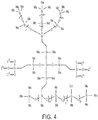
- the composite membrane may include the polymer material of FIG. 4 .
- the polymer material of FIG. 4 has formula (I), in which p is from 0.20 to 0.50; each R 1 is octyl (Oct); each Q is R 3 , as previously defined; d and m are as previously defined; and each Z 1 is a crosslinking site to another molecule of the polymer material of FIG. 4 .
- the composite membrane may include the polymer material of FIG. 5 .
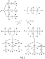
- the polymer material of FIG. 5 has formula (I), in which p is from 0.20 to 0.50; each R 1 is a straight or branched C 5 -C 10 alkyl, a straight chained normal octyl group (Oct), or a C 6 -C 10 aryl group such as phenyl; and each Q is a crosslinking site Z 1 to a second copolymer having a polysiloxane backbone according to formula (II) as previously defined.
- each G 1 is a dimethylsiloxyl monomer (each R 7 of each monomer G 1 is methyl) and each G 2 is independently chosen from internal-network monomers having formula (G2):
- R 4 is as defined in formula (I), namely, a T-structured polysiloxane according to formula (Q2).
- at least one monomer L is a linking monomer having formula (G3), in which Z 2 is the crosslinking site Z 1 of the first copolymer.
- the first copolymer and the second copolymer are linked through at least one alkylene linkage Si-C-C-Si.
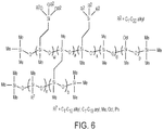
- the composite membrane may include the polymer material of FIG. 6 .
- the polymer material of FIG. 6 has formula (I), in which p is from 0.20 to 0.50 and each R 1 of the substituted methylsiloxane monomers A 2 is octyl (Oct).
- subscript n of formula (I) equals the sum w + a +x, where subscript a is the fraction of monomers that are crosslinking monomers according to formula (M2) in which Q is a crosslinking site Z 1 to a second copolymer having a polysiloxane backbone according to formula (II); subscript x is the fraction of monomers that are alkylsilyl monomers according to formula (M2) in which Q is ⁇ Si(R 2 ) 3 ; and subscript w is the fraction of monomers that are in which Q is ⁇ Si(OR 2 ) 3 .
- any of subscripts w, a, or x may be zero, provided w + a + x is greater than zero.
- the internal-network monomers A 3 of the polymer material of FIG. 6 include at least one crosslinking monomer. In such cases, subscript a is necessarily greater than zero and subscripts w and x may be zero or nonzero.
- the internal-network monomers A 3 of the polymer material of FIG. 6 may include at least one alkylsilyl monomer, at least one alkoxysilyl monomer, and at least one crosslinking monomer. In such cases, all subscripts w, a, and x are greater than zero.
- Each R 7 of the polymer material of FIG. 6 may be selected from the group consisting of methyl, ethyl, propyl, butyl, pentyl, hexyl, heptyl, octyl, nonyl, and phenyl.
- Each R 7 of the polymer material of FIG. 6 may be methyl.
- Each R 7 of the polymer material of FIG. 6 may be octyl.
- Each R 7 of the polymer material of FIG. 6 may be phenyl.
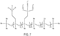
- the composite membrane may include the polymer material of FIG. 7 .
- the polymer material of FIG. 7 has formula (I), in which p is from 0.20 to 0.50; d and m within respective ranges previously defined; each R 1 of the substituted methylsiloxane monomers A 2 is octyl (Oct); each Q of the internal-network monomers A 3 is independently chosen from ⁇ Si(R 2 ) 3 or R 5 , where R 2 is C 1 ⁇ C 20 alkyl and R 5 is a crosslinking group having formula (X1) as previously defined; and each Z 1 is a crosslinking site to another copolymer molecule, for example to another molecule of a copolymer according to FIG. 7 .
- each R 2 is ethyl (Et), it should be understood that each R 2 may be chosen from any C 1 -C 20 alkyl as previously defined.
- the internal-network monomers A 3 may be selected from the group consisting of alkylsilyl monomers according to formula (M2) in which Q is ⁇ Si(R 2 ) 3 ; crosslinking monomers according to formula (M2) in which Q is R 5 ; and combinations thereof.
- the subscript x which represents a mole fraction of internal-network monomers that are alkylsilyl monomers in the polymer material of FIG. 7 , may be zero or nonzero.
- the subscript m of the polymer material of FIG. 7 must be greater than zero, and accordingly the subscript x must be less than subscript m.
- the composite membrane may include a polymer material according to formula (I), in which internal-network monomers A 3 include at least one alkylsilyl monomer according to formula (M2) in which Q is ⁇ Si(R 2 ) 3 ; and at least one crosslinking monomer according to formula (M2) in which Q is R 5 .
- An example of such cases includes the polymer material of FIG. 7 , in which subscript x and subscript m are both greater than zero and m is greater than x.
- the composite membrane may include the polymer material of FIG. 8 .
- the polymer material of FIG. 8 has formula (I), in which the internal-network monomers A 3 include or are selected from the group consisting of monomers according to formula (M2) in which Q is R 3 ; crosslinking monomers according to formula (M2) in which Q is ⁇ (CH 2 ) z ⁇ R 5 , where R 5 is a crosslinking group having formula (X1) as previously defined, and where z is from 1 to 10; and combinations thereof.
- the material of FIG. 8 is a polymer material according to formula (I), in which subscript p is 0.
- the subscript x which represents a mole fraction of internal-network monomers in the polymer material of FIG.
- each Q is ⁇ (CH 2 ) z ⁇ R 5 , where subscript z is 1.
- Each Z 1 in FIG. 8 is a crosslinking site at an end of a group R 5 to another copolymer molecule, for example to another molecule of a copolymer according to FIG. 8 .
- the subscript x in the copolymer of FIG. 8 which represents a mole fraction of internal-network monomers for which Q is R 3 , may be zero or nonzero.
- the subscript m of the polymer material of FIG. 8 must be greater than zero, and accordingly the subscript x must be less than subscript m.
- the composite membrane may include a polymer material according to formula (I), in which internal-network monomers A 3 include at least one crosslinking monomer according to formula (M2) in which Q is ⁇ (CH 2 ) z ⁇ R 5 .
- the composite membrane may include a polymer material according to formula (I), in which internal-network monomers A 3 include both at least one crosslinking monomer according to formula (M2) in which Q is ⁇ (CH 2 ) z ⁇ R 5 and at least one crosslinking monomer according to formula (M2) in which Q is R 3 .
- An example of such cases includes the polymer material of FIG. 8 , in which subscript x and subscript m are both greater than zero and m is greater than x.
- the composite membrane may include a polymer material according to formula (I), in which internal-network monomers include at least one monomer according to formula (M2) in which Q is R 3 ; and at least one crosslinking monomer according to formula (M2) in which Q is ⁇ (CH 2 ) z ⁇ R 5 , where z is 1.
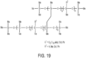
- the composite membrane material may include a polymer material of FIG. 19 .
- the polymer material of FIG. 19 has formula (I), in which the substituted methylsiloxyl monomers A 2 according to formula (M1) may have a group R 1 that is C 5 ⁇ C 10 alkyl, octyl, or phenyl.
- the groups R 1 in a single polymer material according to FIG. 19 may all be the same, or some groups R 1 may differ from other groups R 1 .
- R 7 may be C 1 ⁇ C 10 alkyl (such as, for example, methyl or octyl), or C 6 ⁇ C 10 aryl (such as phenyl, for example).
- the groups R 7 in a single polymer material according to FIG. 19 may all be the same, or some groups R 7 may differ from other groups R 7 .
- the subscript p is from 0.20 to 0.50; the subscript m is from 0.01 to 0.20; and d + p + m is equal to 1.
- the subscript n may is from 0.005 to 0.55.
- the subscript "b" may equal 1 - n and, therefore, may be generally from 0.45 to 0.995.
- all groups R 7 are methyl.
- all groups R 7 are octyl; subscript n is from 0.25 to 0.30; and subscript b is from 0.70 to 0.75.
- all groups R 7 are phenyl; subscript n is from 0.45 to 0.50; and subscript b is from 0.50 to 0.55.
- the composite membrane material may include a polymer material of FIG. 20 .
- the composite membranes of Figure 20 are provided for reference purposes only.
- the polymer material of FIG. 20 has formula (I), in which the substituted methylsiloxyl monomers A 2 are phenylmethylsiloxyl monomers according to formula (M1), where each group R 1 is phenyl.
- the internal-network monomers A 3 of the polymer material according to FIG. 20 have formula (M2), where Q is a group R 4 , particularly, a group according to formula (Q3), in which the subscript y is an integer from 1 to 850, from 1 to 500, from 1 to 100, from 1 to 50, from 1 to 40, from 1 to 30, from 1 to 20, from 1 to 10, or from 1 to 5.
- the subscript p may be from 0.20 to 0.50; the subscript m may be from 0.01 to 0.20; and d + p + m may be less than or equal to 1.
- a first synthetic scheme includes reaction of a molecule, such as a silane or a siloxane, that includes vinyl groups (for example, the vinyl-T structure polysiloxanes of FIG. 3 ) with a polymer having methylhydrosiloxane monomers, such that the backbone of the polymer having the methylhydrosiloxane monomers becomes the backbone of the first copolymer or the second copolymer of the polymer material.
- the vinyl groups react with the hydrogen atoms of the methylhydrosiloxane monomers to form Si-C-C-Si alkylene linkages.
- the molecule having vinyl groups may be reacted with the polymer having methylhydrosiloxane monomers in a molar amount that leaves some methylhydrosiloxane monomers unreacted.
- the reaction product of the molecule including vinyl groups with the polymer having methylhydrosiloxane monomers may be used as a crosslinking agent.
- Such a crosslinking agent may be further reacted with a prepolymer molecule such as a vinylmethylsiloxane-alkylmethylsiloxane-dimethylsiloxane terpolymer such as, for example, a vinylmethylsiloxane-octylmethylsiloxane-dimethylsiloxane terpolymer.
- prepolymer molecules include vinylmethylsiloxane-arylmethylsiloxane-dimethylsiloxane terpolymers such as, for example, vinylmethylsiloxane-phenylmethylsiloxane-dimethylsiloxane terpolymers.
- the unreacted methylhydrosiloxane monomers of the crosslinking agent then react with the vinyl groups of the terpolymers to form a crosslinked copolymer having two copolymer backbones linked through Si-C-C-Si alkylene linkages.
- the first reaction scheme may be followed to prepare the polymer materials of FIGS. 4 and 5 , as further described in Examples 1 and 2.
- a prepolymer molecule such as a vinylmethylsiloxane-alkylmethylsiloxane-dimethylsiloxane terpolymer or, for example, a vinylmethylsiloxane-octylmethylsiloxane-dimethylsiloxane terpolymer, may be modified by reacting the prepolymer with any functionalized silane such as, for example, a trialkoxylsilane and optionally a trialkylsilane in addition to the trialkoxysilane, to form a crosslinkable prepolymer.
- any functionalized silane such as, for example, a trialkoxylsilane and optionally a trialkylsilane in addition to the trialkoxysilane
- the silanes react with the vinylmethylsiloxane monomers to form side group functionalities linked to a polymer backbone through Si-C-C-Si alkylene linkages.
- the silanes are reacted at a molar amount such that some of the vinylmethylsiloxane monomers remain unreacted.
- the reaction product may then be reacted with a crosslinking agent, such as a copolymer that includes methylhydrosiloxane monomers.
- a crosslinking agent such as a copolymer that includes methylhydrosiloxane monomers.
- the unreacted vinylmethylsiloxane monomers of the crosslinkable polymer react with the methylhydrosiloxane monomers to form a polymer material having two polymer backbones linked through one or more Si-C-C-Si alkylene linkages.
- the second reaction scheme may be followed to prepare the polymer materials of FIG. 6 , as further described in Examples 3-5.
- a prepolymer molecule such as a vinylmethylsiloxane-alkylmethylsiloxane-dimethylsiloxane terpolymer or, for example, a vinylmethylsiloxane-octylmethylsiloxane-dimethylsiloxane terpolymer, may be modified by reacting the prepolymer with any functionalized silane such as, for example, a trialkoxylsilane and optionally a trialkylsilane in addition to the trialkoxysilane, to form a modified prepolymer.
- any functionalized silane such as, for example, a trialkoxylsilane and optionally a trialkylsilane in addition to the trialkoxysilane
- the silanes react with the vinylmethylsiloxane monomers to form side group functionalities linked to a polymer backbone through Si-C-C-Si alkylene linkages.
- the trialkoxysilane side groups of the modified prepolymer may then be hydrolyzed to trihydroxysilane side groups to form a crosslinkable copolymer.
- the crosslinkable copolymer may then be crosslinked by a mild heat treatment in the presence of an appropriate catalyst, so that the trihydroxysilane side groups crosslink to other molecules of the crosslinkable copolymer.
- the third reaction scheme may be followed to prepare the polymer materials of FIG. 7 , as further described in Example 6.
- a first molecule including vinyl groups for example, the vinyl-T structure polysiloxanes of FIG. 3
- an alkyltrialkoxysilane, in which the alkyl group is a terminal olefin, is reacted with a polymer having methylhydrosiloxane monomers.
- alkyltrialkoxysilanes include vinyltrialkoxysilanes and allyltrialkoxysilanes.
- the vinyl groups of the first molecule and the alkyltrialkoxysilane react with the hydrogen atoms of the methylhydrosiloxane monomers to form side groups having Si-C-C-Si alkylene linkages to the copolymer backbone.
- the side groups resulting from the alkyltrialkoxysilane may be hydrolyzed to form a crosslinkable copolymer having alkyltrihydroxysilyl side groups.
- the crosslinkable copolymer may then be crosslinked by a mild heat treatment in the presence of an appropriate catalyst, so that the trihydroxysilane side groups crosslink to other molecules of the crosslinkable copolymer.
- the fourth reaction scheme may be followed to prepare the polymer materials of FIG. 8 , as further described in Example 7.
- the composite membranes according to various embodiments may be prepared by casting a separation layer solution containing any of the polymer materials previously described, dissolved in an appropriate solvent such as chloroform or hexane, for example, onto a polymer support.
- Suitable polymer supports include microporous supports such as, for example, polyacrylonitrile, polyvinylidene fluoride, or polyether sulfone.
- the polymer materials as cast may be dried and further subjected to a mild heat treatment to fully crosslink the membrane on the polymer support.
- the resulting functionalized and crosslinked siloxane composite membranes may then be incorporated into a gas-separation system or used to separate heavy hydrocarbons from natural gas.
- Composite membranes including the polymer materials previously described exhibit enhanced permeance to heavy hydrocarbons and enhanced selectivity of heavy hydrocarbons over gases such as methane, carbon dioxide, oxygen, and nitrogen.
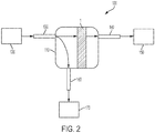
- a system 100 for removing heavy hydrocarbons from natural gas includes a separator unit 110 having comprising an inlet 130, a retentate outlet 160, and a permeate outlet 140.
- a natural-gas source 120 is connected in fluidic communication with the inlet 130 of the separator unit 110, such that a fluid (liquid, gas, or vapor) may flow freely between the natural-gas source 120 and the inlet 130.
- the system 100 further includes at least one composite membrane 1 according to any embodiment of this disclosure, configured within the separator unit 110 to prevent a flow of fluids from the inlet 130 to the permeate outlet 140 without first passing through the at least one composite membrane 1 and to permit the flow of fluids to proceed from the inlet 130 to the retentate outlet 160 without passing through the at least one composite membrane 1.
- the system 100 further includes a retentate collector 170 in fluidic communication with the retentate outlet 160 of the separator unit 110.
- the system 100 further includes a permeate collector 150 in fluidic communication with the permeate outlet 140 of the separator unit 110.
- fluids that reach the permeate collector 150 are enriched in heavy hydrocarbons, relative to the fluids that initially reach the separator unit 110 from the natural gas source 120 through the inlet 130.
- fluids that reach the retentate collector 170 have a decreased fraction of heavy hydrocarbons, relative to the fluids that initially reach the separator unit 110 from the natural gas source 120 through the inlet 130.
- the permeate collector 150 collects a permeate containing heavy hydrocarbons having at least three carbon atoms.
- the system 100 for removing heavy hydrocarbons from natural gas may include multiple separator units each having at least one composite membrane according to embodiments of this disclosure.
- the separator unit 110 or multiple separator units may include more than one composite membrane, each of which may include a polymer material that is the same as or different from that of any other composite membrane in an individual separator unit or in another separator unit of the system.
- the composite membrane of the system includes a polymer material according to formula (I) as previously defined, in which subscript p is from 0.20 to 0.50.
- the composite membrane of the system includes a polymer material according to formula (I) as previously defined, in which each R 1 of the polymer material is octyl.
- the polymer material of the composite membrane is coated onto a porous support layer, and the porous support later is interposed between the polymer material and the nonwoven material.
- the nonwoven material may be poly(ethylene terephthalate) and the porous support layer may be chosen from polyacrylonitrile, poly(vinylidene fluoride), or polyether sulfone.
- FIG. 2 is intended to illustrate only a basic configuration of the system 100 and omits conventional equipment such as compressors, valves, heaters or coolers, fans, circulators, control apparatus, pressure sensors, or the like, which may be implemented in a large-scale system.
- separator units may be configured such that the incoming fluid through the inlet enters parallel to the composite membrane.
- a carrier gas may be introduced into the separator unit on the side of the composite membrane opposite the inlet, as a means to facilitate removal of permeate fluids.
- the carrier gas and the incoming natural gas may flow through the separator unit in a co-flow (same direction) or a counterflow (opposite directions) pathway.
- methods for removing heavy hydrocarbons from natural gas include introducing the natural gas stream at a feed pressure into a separator unit 110 comprising an inlet 130, a retentate outlet 160, a permeate outlet 140, and at least one composite membrane 1 according to any embodiment of this disclosure.
- the at least one composite membrane 1 is configured within the separator unit 110 to prevent a flow of fluids from the inlet 130 to the permeate outlet 140 without first passing through the at least one composite membrane 1 and to permit the flow of fluids to proceed from the inlet 130 to the retentate outlet 160 without passing through the at least one composite membrane 1.
- the method further includes collecting at least one of (1) a retentate from the retentate outlet 160, the retentate having a reduced volume fraction of the heavy hydrocarbons, the reduced volume fraction being less than the initial volume fraction; or (2) a permeate from the permeate outlet 140, the permeate having an increased volume fraction of the heavy hydrocarbons, the increased volume fraction being greater than the initial volume fraction.
- the methods may include establishing a feed pressure to the natural gas source 120.
- a suitable feed pressure may include from 100 kPa (1 bar) to 1 MPa (10 bar).
- the methods may include establishing a separation temperature of the separator unit 110. Examples of suitable separation temperatures for separating heavy hydrocarbons from natural gas may include from 20 °C to 100 °C.
- composite membranes according to embodiments of this application were prepared by casting a separation layer solution containing a polymer material onto microporous polymer supports using conventional casting techniques such as application by a doctor blade, then drying the separation layer solution to remove residual solvents.
- Preparations of the polymer materials according to the structures in FIGS. 4 - 8 , 19 , and 20 are described in Examples 1-7 and 11-20.
- conventional composite membranes of poly(dimethylsiloxane) (PDMS) and poly(octylmethylsiloxane) (POMS) were prepared as described in Comparative Example 8.
- Membrane transport properties of the composite membrane of Example 2 are provided in Example 9; properties of the composite membrane of Example 6 are provided in Example 10; and properties of selected composite membranes of Examples 11-20 are provided in Example 21.
- Composite Membrane 1 includes the polymer material of FIG. 4 on a microporous polymer support.
- the polymer material of FIG. 4 is prepared by first preparing a crosslinker agent, then reacting the crosslinker agent with a modified PDMS prepolymer, specifically a methyloctylvinyl terpolymer, to form a separation solution. The separation solution is then cast onto the microporous polymer support and cured.
- a silane such as tetrakis(dimethylsiloxyl)silane or 2,4,6,8-tetramethylcyclotetrasiloxane is dissolved in organic solvents such as chloroform or hexane with a vinyl T-structured polymer under vigorous mechanical stirring.
- the vinyl T-structured polymer has formula (E1), where the subscript y is an integer from 1 to 850, from 1 to 100, from 1 to 50, from 1 to 20, from 1 to 10, or from 1 to 5:
- a catalyst such as 1,3-diethenyl-1,1,3,3-tetramethyldisiloxane platinum complex is added into the mixed solution under nitrogen gas protection.
- the reaction is maintained for about 2 hours 25 °C and then for an additional 2 hours at 40 °C under mechanical stirring to yield a light yellow, transparent crosslinking agent having formula (E2):
- the crosslinking agent is then reacted with a prepolymer to form a separation layer.
- the particular prepolymer is a methyl-terminated vinylmethylsiloxane-octylmethylsiloxane-dimethylsiloxane terpolymer having a molecular weight of 10,000 Dalton to 12,000 Dalton and containing 3% to 5% vinylmethylsiloxane monomers, based on the total number of monomers other than the terminal monomers.
- the crosslinking agent and a prepolymer are dissolved in an organic solvent such as chloroform or hexane under mechanical stirring to form a homogeneous solution.
- a catalyst such as 1,3-diethenyl-1,1,3,3-tetramethyldisiloxane platinum complex is added slowly into the solution, followed by stirring for 5 minutes to 30 minutes at 25 °C. The obtained solution is then degassed and prepared for coating.
- the composite membrane is fabricated by casting the separation layer solution onto a microporous polymer support such as polyacrylonitrile (with molecular weight cut-off (MWCO) of 150k), polyvinylidene fluoride (MWCO 75k to 250k), or polyether sulfone (MWCO 10k to 20k) at 25 °C.
- MWCO molecular weight cut-off
- the resulting composite membrane is dried at 25 °C overnight to remove solvent.
- the composite membrane is then crosslinked in an oven at 50 °C to 100 °C for 24 hours to 72 hours, particularly from 60 °C to 75 °C for about 48 hours.
- Composite Membrane 2 includes the polymer material of FIG. 5 , where R 1 is octyl, on a microporous polymer support.
- the polymer material of FIG. 5 where R 1 is octyl is prepared by the same method as described for Composite Membrane 1 in Example 1, except that the crosslinking agent is formed by reacting the vinyl T-structured polymer of formula (E1) with a methylhydrosiloxane-dimethylsiloxane copolymer according to formula (E4), where k is from 0.01 to 0.55, having a viscosity from 0.01 Pa ⁇ s (10 cP) to 8 Pa ⁇ s (8,000 cP):
- the vinyl groups of the vinyl T-structured polymer replaces the hydrogen atoms of the methylhydrosiloxane monomers to form Si-C-C-Si linkages.
- the vinyl T-structured polymer is added to the initial reaction mixture with the methylhydrosiloxane-dimethylsiloxane copolymer in an amount that results in reaction of fewer than all methylhydrosiloxane monomers of the methylhydrosiloxane-dimethylsiloxane copolymer with the vinyl T-structured polymer.
- the crosslinking agent for preparing Composite Membrane 2 has formula (E5), where n is the same as in the methylhydrosiloxane-dimethylsiloxane copolymer of formula (E4), and b equals k of the copolymer of formula (E4) minus q.
- the crosslinking agent is then reacted with the prepolymer vinylmethylsiloxane-octylmethylsiloxane-dimethylsiloxane terpolymer, as previously described in Example 1, to form a separation layer solution.
- the separation layer solution is then cast onto a microporous polymer support, dried, and crosslinked.
- vinyl groups of the prepolymer react with the remaining hydrogen atoms of the methylhydrosiloxane monomers of the crosslinking agent to form additional Si-C-C-Si linkages.
- Composite Membrane 3 includes the polymer material of FIG. 6 on a microporous polymer support, specifically where R 7 is methyl, groups ⁇ OR 2 are methoxy, and groups R 2 bonded directly to silicon atoms are ethyl.
- the polymer material of Composite Membrane 3 is prepared by first modifying a prepolymer according to formula (E3) to incorporate additional functionalities including Si-C-C-Si units, then addition curing the modified prepolymer with a crosslinking agent.
- a polymer according to formula (E3) where p is from 0.35 to 0.40 and m is from 0.03 to 0.05, is dissolved in an organic solvent such as chloroform or hexane under vigorous mechanical stirring.
- a trialkylsilane such as triethylsilane, a trialkoxysilane such as trimethoxysilane, or a combination of a trialkylsilane and a trialkoysilane, may be added at a molar amount that results in reaction of the silanes with fewer than all of the monomers of the prepolymer that have vinyl groups.
- the silanes may be added at an amount that results in from 1% to 99% of the vinyl monomers being unreacted after the modification.
- a catalyst such as 1,3-diethenyl-1,1,3,3-tetramethyldisiloxane platinum complex is added into the mixed solution under nitrogen gas protection.
- the reaction is maintained for about 2 hours 25 °C and then for an additional 2 hours at 40 °C under mechanical stirring to yield a modified prepolymer having formula (E6), where w and x are greater than or equal to zero, provided w + x is greater than zero; w + a + x equals m of the polymer according to formula (E3); and d and p are the same values as the corresponding values in the polymer according to formula (E3).
- a separation solution is then prepared by dissolving the modified prepolymer in an organic solvent such as chloroform or hexane under vigorous mechanical stirring and adding a crosslinking agent according to formula (E7), where R 7 is methyl, subscript n is from 0.01 to 0.99, and subscript b is from 0.01 to 0.55 or from 0.01 to 0.10 or from 0.01 to 0.05:
- the crosslinking agent may be added in an appropriate molar amount such that the number of available methylhydrosiloxane monomer units (subscript b) of the crosslinking agent in solution is equal to the number of unreacted methylvinylsiloxane monomer units (subscript a in formula (E6)) of the prepolymer in solution.
- the crosslinking agent may have a viscosity ranging from 0.025 Pa ⁇ s (25 cP) to 8 Pa ⁇ s (8,000 cP).
- the solution containing the dissolved prepolymer and the dissolved crosslinking agent is stirred for about 5 minutes to 30 minutes at 25 °C then is degassed to prepare for coating.
- a catalyst such as 1,3-diethenyl-1,1,3,3-tetramethyldisiloxane platinum complex is added slowly into the solution, followed by stirring for 5 minutes to 30 minutes at 25 °C.
- the obtained separation layer solution is then degassed and prepared for coating.
- the separation layer solution is cast onto a microporous polymer support, dried, and crosslinked, as described in Example 1.
- vinyl groups of the prepolymer react with the hydrogen atoms of the methylhydrosiloxane monomers of the crosslinking agent to form Si ⁇ C ⁇ C ⁇ Si linkages in addition to those formed from adding the functional groups to form the modified prepolymer.
- Composite Membrane 4 includes the polymer material of FIG. 6 on a microporous polymer support, specifically where R 7 is octyl, where groups ⁇ OR 2 are methoxy, and where groups R 2 bonded directly to silicon atoms are ethyl.
- the polymer material and Composite Membrane 4 are prepared in a manner identical to that of Composite Membrane 3 described in Example 3, except that the crosslinking agent is a methylhydrosiloxane-octylmethylsiloxane copolymer according to formula (E7) where R 7 is octyl, where subscript n is from 0.01 to 0.99, and where subscript b is from 0.15 to 0.50, or from 0.20 to 0.40, or from 0.25 to 0.30.
- the crosslinking agent may have a viscosity of 0.03 Pa ⁇ s (30 cP) to 0.06 Pa ⁇ s (60 cP).
- Composite Membrane 5 includes the polymer material of FIG. 6 on a microporous polymer support, specifically where R 7 is phenyl, groups ⁇ OR 2 are methoxy, and groups R 2 bonded directly to silicon atoms are ethyl.
- the polymer material and Composite Membrane 5 are prepared in a manner identical to that of Composite Membrane 3 described in Example 3, except that the crosslinking agent is a methylhydrosiloxane-methylphenylsiloxane copolymer according to formula (E7) where R 7 is phenyl, subscript n is from 0.01 to 0.99, and subscript b is from 0.30 to 0.60 or from 0.40 to 0.55 or from 0.45 to 0.50.
- the crosslinking agent may have a viscosity of 0.075 Pa ⁇ s (75 cP) to 0.11 Pa ⁇ s (110 cP).
- Composite Membrane 6 includes the polymer material of FIG. 7 on a microporous polymer support.
- the polymer material of Composite Membrane 6 is prepared by first modifying a prepolymer according to formula (E3) to incorporate additional functionalities including Si-C-C-Si units having hydrolysable groups, then hydrolyzing and crosslinking the modified prepolymer without adding an additional crosslinking agent.
- a polymer according to formula (E3) where p is from 0.35 to 0.40 and m is from 0.03 to 0.05, is dissolved in an organic solvent such as chloroform or hexane under vigorous mechanical stirring.
- a trialkoxysilane such as trimethoxysilane and, optionally in addition to the trialkoxylsilane, a trialkylsilane such as triethylsilane, may be added at a molar amount that results in reaction of the silanes with all of the monomers of the prepolymer that have vinyl groups.
- the modified prepolymer may have formula (E6), as in Example 3, but where the subscript a representing unreacted vinyl groups is zero.
- the modified prepolymer is then reacted with water in the presence of an appropriate catalyst such as dibutyltin dilaurate (DBTDL), for example, or with a silanol compound, to replace silicon-bonded methoxy groups with hydroxyl groups with liberation of one molecule of methanol for every converted methoxy group.
- DBTDL dibutyltin dilaurate
- silanol compound a silanol compound
- the separation layer solution is cast onto a microporous polymer support, dried, and crosslinked, as described in Example 1.
- a hydroxy group from each of two molecules of the compound of formula (E8) react with release of one molecule of water to form an intermolecular crosslink, one of which is illustrated as formula (E9):
- Example 10 Characterizations and data with regard to a composite membrane prepared according to the foregoing procedure are provided in Example 10.
- Composite Membrane 7 includes the polymer material of FIG. 8 on a microporous polymer support.
- the polymer material of Composite Membrane 7 is prepared by first dissolving in organic solvent the copolymer having formula (E10), where m is from 0.01 to 0.55 and x is less than m.
- the copolymer having formula (E10) is prepared in the same manner as the crosslinking agent of formula (E5) in Example 2 of this specification.
- a silane having shorter ⁇ -alkenyl group such as vinyl (z is zero) or a longer alkenyl group where z is an integer from 2 to 10.
- the length of the ⁇ -alkenyl group of the ⁇ -alkenyltrialkoxysilane determines the length of crosslinking monomers present in the polymer material of Composite Membrane 7.
- a catalyst such as 1,3-diethenyl-1,1,3,3-tetramethyldisiloxane platinum complex is added slowly into the solution, followed by stirring for 5 minutes to 30 minutes at 25 °C.
- the hydrogen atoms of the methylhydrosiloxane monomers of the copolymer are replaced with trimethoxysilyl-terminated groups ⁇ (CH 2 ) 3 Si(OCH 3 ) 3 .
- the separation layer solution is prepared by hydrolyzing this reaction product using a mild catalyst such as acetic acid to form a crosslinkable compound. By the hydrolysis, the trimethoxysilyl-terminated groups of the initial reaction product are converted to trihydroxysilyl-terminated groups ⁇ (CH 2 ) 3 Si(OH) 3 in the crosslinkable compound.
- the separation layer solution containing the crosslinkable compound is cast onto a microporous polymer support, dried, and crosslinked, as described in Example 1.
- the hydroxyl groups of trihydroxysilyl-terminated groups ⁇ (CH 2 ) 3 Si(OH) 3 from each of two molecules of the crosslinkable compound react with release of one molecule of water to form an intermolecular crosslink.
- PDMS poly(dimethylsiloxane)
- POMS poly(octylmethylsiloxane)
- Separation layer solutions of the PDMS and the POMS were prepared by dissolving polymer in an organic solvent such as chloroform or hexane and casting the separation layer solution onto a microporous polymer support and drying at 25 °C overnight to remove solvent.
- a supported membrane having the polymer material of FIG. 5 was prepared according to the procedure of Example 2 of this disclosure using polyacrylonitrile and non-woven poly(ethylene terephthalate) as the support.
- the supported films had uniform separation layer thicknesses of from 0.5 ⁇ m to 50 ⁇ m, uniform microporous support layer thicknesses of 30 ⁇ m to 60 ⁇ m, and non-woven structural support layer thickness of 100 ⁇ m to 250 ⁇ m.
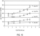
- the supported membrane was characterized to determine permeability of the supported membrane to propane (C 3 H 8 ) and butane (C 4 H 10 ) at various pressures and temperatures, and to determine ratios of propane to methane (CH 4 ) ideal selectivity and butane to methane ideal selectivity.
- polymer membranes separate components of a gas or vapor mixture because the components permeate the membrane at different rates.
- the permeability of a polymer membrane material for a gas, P [in units Barrer, where 1 Barrer 10 -10 (cm 3 STP ⁇ cm)/(cm 2 ⁇ s ⁇ cm Hg )], is the rate at which that gas moves through a standard thickness [1 cm] of the membrane under a standard driving force (a pressure difference of 1 cm Hg ).
- a measure of the ability of a membrane to separate two gases is the selectivity, ⁇ , defined as the ratio of the gas permeabilities, P 1 /P 2 .
- D is the diffusion coefficient of the gas in the membrane (in units cm 2 /s), which is a measure of the gas mobility
- k is the Henry's law sorption coefficient, which links the concentration of the gas in the membrane material to the pressure in the adjacent gas (in units cm 3 STP /cm 3 ⁇ cm Hg ).
- the ideal selectivity of a polymer material is established by measuring the permeabilities with pure gas or vapor samples, then calculating the ratio.
- the actual selectivity obtained in a real separation process is established by making permeation measurements with gas mixtures. Both high permeability and high selectivity are desirable, because a higher permeability decreases the size of membrane necessary to treat a given amount of gas, while higher selectivity results in a more highly purified product.
- Equation 1 P is the permeability, v is the volume of the downstream chamber, l is the membrane thickness, R is the ideal gas constant, T is the absolute temperature, SA is the surface area of the membrane, and p is the upstream pressure.
- the ratio of permeabilities is calculated for a given gas pair (C 3 H 8 /CH 4 or C 4 H 10 /CH 4 ) at the same pressure and temperature.
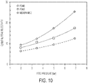
- Composite Membrane 2 had a C 3 H 8 permeability of about 1.87 x 10 -12 (mol ⁇ m)/(m 2 ⁇ s ⁇ Pa) (5,584 Barrer), compared to about 9.38 x 10 -13 and 9.72 x 10 -13 (mol ⁇ m)/(m 2 ⁇ s ⁇ Pa) (2,800 and 2,900 Barrer) for both PDMS and POMS, respectively.
- Composite Membrane 2 had a C 3 H 8 permeability of about 6.50 x 10 -12 (mol ⁇ m)/(m 2 ⁇ s ⁇ Pa) (19,400 Barrer), compared to about 1.91 x 10 -12 (mol ⁇ m)/(m 2 ⁇ s ⁇ Pa) (5,700 Barrer) for POMS and 1.57 ⁇ 10 -12 (4,700 Barrer) for PDMS.
- Composite Membrane 2 had a C 3 H 8 /CH 4 ideal selectivity of about 9.4, which increased by about 171% to about 25 at 700 kPa (7.0 bar).
- the corresponding increase for POMS was about 117% [8.0 at 200 kPa (2.0 bar) and 17.4 at 700 kPa (7.0 bar)]
- the corresponding increase for PDMS was about 95% [6.4 at 200 kPa (2.0 bar) and 12.4 at 700 kPa (7.0 bar)].
- Composite Membrane 2 had a C 4 H 10 /CH 4 ideal selectivity of about 21.9, which increased by about 344% to about 97.3 at 206.8 kPa (30 psi).
- the corresponding increase for POMS was about 200% (19.3 at 48.3 kPa (7 psi) and 57.9 at 206.8 kPa (30 psi)), and the corresponding increase for PDMS was about 272% (9.6 at 48.3 kPa (7 psi) and 35.6 at 206.8 kPa (30 psi)).
- the Composite Membrane 2 was both more permeable to C 3 H 8 than were PDMS and POMS, and the Composite Membrane 2 was more selective to C 3 H 8 over CH 4 than were PDMS and POMS.
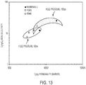
- C 4 H 10 permeability versus C 4 H 10 /CH 4 ideal selectivity is plotted for PDMS, POMS, and Composite Membrane 2, measured at a temperature of 25 °C and at feed pressures of 100 kPa (1 bar) and 200 kPa (2 bar). At both 100 kPa (1 bar) and 200 kPa (2 bar), the Composite Membrane 2 was both more permeable to C 4 H 10 than were PDMS and POMS, and the Composite Membrane 2 was more selective to C 4 H 10 over CH 4 than were PDMS and POMS.
- Composite Membrane 2 was approximately 3.6 times more permeable to C 3 H 8 than to CO 2 , approximately 13.9 times more permeable to C 3 H 8 than to H 2 , approximately 16.4 times more permeable to C 3 H 8 than to CH 4 , and approximately 47.2 times more permeable to C 3 H 8 than to N 2 .
- a supported membrane (Composite Membrane 6) having the polymer material of FIG. 7 was prepared according to the procedure of Example 6 of this disclosure.
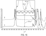
- the supported membrane was characterized to evaluate its FTIR spectrum before and after crosslinking, the effects of feed pressure on C 3 H 8 permeability, the effects of the operating temperature on C 3 H 8 /CH 4 ideal selectivity, and selectivity of C 3 H 8 over various gases as a function of feed pressure.
- FTIR Fourier-Transform infrared
- Composite Membrane 8 includes the polymer material of FIG. 19 , where R 1 is octyl and R 7 is hydrogen, on a microporous polymer support.
- the prepolymer is dissolved in organic solvent and reacted in the presence of a catalyst with a crosslinking agent according to formula (E7) (see Example 3), where R 7 is hydrogen, n is 0.5, and b is 0.5.
- a separation layer solution of the resulting polymer is then cast onto a microporous polymer support, dried, and crosslinked, as described in Example 1.
- An exemplary Composite Membrane 8 was prepared by the foregoing method with a crosslinking agent having a weight-average molecular weight of 1400 Dalton to 2400 Dalton. Characterization data for the exemplary Composite Membrane 8 are provided in Example 21.
- Composite Membrane 9 includes the polymer material of FIG. 19 , where R 1 is octyl and R 7 is methyl, on a microporous polymer support.
- the prepolymer is dissolved in organic solvent and reacted in the presence of a catalyst with a crosslinking agent according to formula (E7) (see Example 3), where R 7 is methyl, n is from 0.005 to 0.55, and b is from 0.45 to 0.995.
- a separation layer solution of the resulting polymer is then cast onto a microporous polymer support, dried, and crosslinked, as described in Example 1.
- An exemplary Composite Membrane 9 was prepared by the foregoing method with a crosslinking agent having a weight-average molecular weight of 900 Dalton to 65,000 Dalton. Characterization data for the exemplary Composite Membrane 9 are provided in Example 21.
- Composite Membrane 10 includes the polymer material of FIG. 19 , where R 1 is octyl and R 7 is octyl, on a microporous polymer support.
- the prepolymer is dissolved in organic solvent and reacted in the presence of a catalyst with a crosslinking agent according to formula (E7) (see Example 3), where R 7 is octyl, n is from 0.25 to 0.30, and b is from 0.70 to 0.75.
- a separation layer solution of the resulting polymer is then cast onto a microporous polymer support, dried, and crosslinked, as described in Example 1.
- An exemplary Composite Membrane 10 was prepared by the foregoing method with a crosslinking agent having a weight-average molecular weight of 280 Dalton to 480 Dalton. Characterization data for the exemplary Composite Membrane 8 are provided in Example 21.
- Composite Membrane 11 includes the polymer material of FIG. 19 , where R 1 is octyl and R 7 is phenyl, on a microporous polymer support.
- the prepolymer is dissolved in organic solvent and reacted in the presence of a catalyst with a crosslinking agent according to formula (E7) (see Example 3), where R 7 is phenyl, n is from 0.45 to 0.50, and b is from 0.50 to 0.55.
- a separation layer solution of the resulting polymer is then cast onto a microporous polymer support, dried, and crosslinked, as described in Example 1.
- An exemplary Composite Membrane 11 was prepared by the foregoing method with a crosslinking agent having a weight-average molecular weight of 160 Dalton to 170 Dalton. Characterization data for the exemplary Composite Membrane 11 are provided in Example 21.
- Composite Membrane 12 includes the polymer material of FIG. 20 on a microporous support.
- the prepolymer is dissolved in organic solvent and reacted in the presence of a catalyst with a hydride-terminated polymethylsiloxane crosslinking agent according to formula (E11) where y is an integer from 1 to 850, from 1 to 500, from 1 to 100, from 1 to 50, from 1 to 40, from 1 to 30, from 1 to 20, from 1 to 10, or from 1 to 5:
- a separation layer solution of the resulting polymer is then cast onto a microporous polymer support, dried, and crosslinked, as described in Example 1.
- crosslinking occurs at the crosslinking sites Z 1 , generally through the reaction of the hydride on the end of the crosslinking agent not already attached to a polysiloxane backbone with a vinyl group of a vinylmethylsiloxane monomer in a second polymer backbone.
- An exemplary Composite Membrane 12 was prepared by the foregoing method with a prepolymer having a weight-average molecular weight of 2500 Dalton to 3000 Dalton and a crosslinking agent having a weight-average molecular weight of 400 Dalton to 63,000 Dalton.
- the reaction of the hydride-terminated polymethylsiloxane crosslinking agent according to formula (E11) with the prepolymer according to formula (E3) was considerably faster than the reaction of the crosslinking agent according to formula (E7) with the prepolymer according to formula (E3) in Example 14. It is believed that the greater reactivity of the hydride-terminated polymethylsiloxane crosslinking agent according to formula (E11) resulted in a polymer material of FIG. 20 that was tougher and had a greater crosslinking density than that of the polymer material of FIG. 19 (Example 14).
- Composite Membrane 13 includes the polymer material of FIG. 19 , where R 1 is phenyl and R 7 is hydrogen, on a microporous polymer support.
- the prepolymer is dissolved in organic solvent and reacted in the presence of a catalyst with a crosslinking agent according to formula (E7) (see Example 3), where R 7 is hydrogen, n is 0.50, and b is 0.50.
- a separation layer solution of the resulting polymer is then cast onto a microporous polymer support, dried, and crosslinked, as described in Example 1.
- An exemplary Composite Membrane 13 was prepared by the foregoing method with a prepolymer having a weight-average molecular weight of 2500 Dalton to 3000 Dalton and a crosslinking agent having a weight-average molecular weight of 14,000 Dalton to 24,000 Dalton. Characterization data for the exemplary Composite Membrane 13 are provided in Example 21.
- Composite Membrane 14 includes the polymer material of FIG. 19 , where R 1 is phenyl and R 7 is methyl, on a microporous polymer support.
- the prepolymer is dissolved in organic solvent and reacted in the presence of a catalyst with a crosslinking agent according to formula (E7) (see Example 3), where R 7 is methyl, n is from 0.005 to 0.55, and b is from 0.45 to 0.995.
- a separation layer solution of the resulting polymer is then cast onto a microporous polymer support, dried, and crosslinked, as described in Example 1.
- An exemplary Composite Membrane 14 was prepared by the foregoing method with a prepolymer having a weight-average molecular weight of 2500 Dalton to 3000 Dalton and a crosslinking agent having a weight-average molecular weight of 900 Dalton to 65,000 Dalton.
- Composite Membrane 15 includes the polymer material of FIG. 19 , where R 1 is phenyl and R 7 is octyl, on a microporous polymer support.
- the prepolymer is dissolved in organic solvent and reacted in the presence of a catalyst with a crosslinking agent according to formula (E7) (see Example 3), where R 7 is octyl, n is from 0.25 to 0.30, and b is from 0.70 to 0.75.
- a separation layer solution of the resulting polymer is then cast onto a microporous polymer support, dried, and crosslinked, as described in Example 1.
- An exemplary Composite Membrane 15 was prepared by the foregoing method with a prepolymer having a weight-average molecular weight of 2500 Dalton to 3000 Dalton and a crosslinking agent having a weight-average molecular weight of 280 Dalton to 480 Dalton.
- Composite Membrane 16 includes the polymer material of FIG. 19 , where R 1 is phenyl and R 7 is phenyl, on a microporous polymer support.
- the prepolymer is dissolved in organic solvent and reacted in the presence of a catalyst with a crosslinking agent according to formula (E7) (see Example 3), where R 7 is phenyl, n is from 0.45 to 0.50, and b is from 0.50 to 0.55.
- a separation layer solution of the resulting polymer is then cast onto a microporous polymer support, dried, and crosslinked, as described in Example 1.
- An exemplary Composite Membrane 15 was prepared by the foregoing method with a prepolymer having a weight-average molecular weight of 2500 Dalton to 3000 Dalton and a crosslinking agent having a weight-average molecular weight of 160 Dalton to 170 Dalton.
- Composite Membrane 17 includes the polymer material of FIG. 5 , where R 1 is phenyl, on a microporous polymer support.
- the polymer material of FIG. 5 where R 1 is phenyl is prepared by the same method as described for Composite Membrane 2 in Example 2, except that to form the separation layer the crosslinking agent of formula (E5) is reacted with a prepolymer vinylmethylsiloxane-phenylmethylsiloxane-dimethylsiloxane terpolymer according to formula (E3), where R 1 is phenyl, m is from 0.03 to 0.05, p is from 0.35 to 0.40, having a weight-average molecular weight of 2500 Dalton to 3000 Dalton.
- An exemplary Composite Membrane 17 was prepared by the foregoing method with a prepolymer having a weight-average molecular weight of 2500 Dalton to 3000 Dalton. Characterization data for the exemplary Composite Membrane 17 are provided in Example 21.
- the C 3 H 8 permeabilities and C 3 H 8 /CH 4 ideal selectivities of Composite Membranes 8 ⁇ 11, 13, and 17 and of the PDMS and POMS of Comparative Example 8 were measured at 25 °C, at a feed pressure of 344.7 kPa (50 psi) (3.4 bar) following the measurement procedure described in Example 9 of this disclosure.
- the C 4 H 10 permeabilities and C 4 H 10 /CH 4 ideal selectivities of Composite Membranes 8 ⁇ 11, 13, and 17 were measured at 25 °C, at a feed pressure of 100 kPa (1 bar, 14.5 psi) following the measurement procedure described in Example 9 of this disclosure.
- Table 2 The data from these experiments are summarized in Table 2.
- Composite Membrane 10 had a C 3 H 8 /CH 4 ideal selectivity of about 9.3, which increased by about 245% to about 32 at 700 kPa (7.0 bar), while Composite Membrane 17 had a C 3 H 8 /CH 4 ideal selectivity of about 9.3, which increased by about 127% to about 24 at 700 kPa (7.0 bar).
- the corresponding increase for POMS was about 117% [8.0 at 200 kPa (2.0 bar) and 17.4 at 700 kPa (7.0 bar)]
- the corresponding increase for PDMS was about 95% [6.4 at 200 kPa (2.0 bar) and 12.4 at 700 kPa (7.0 bar)].
Landscapes
- Chemical & Material Sciences (AREA)
- Chemical Kinetics & Catalysis (AREA)
- Oil, Petroleum & Natural Gas (AREA)
- Engineering & Computer Science (AREA)
- General Chemical & Material Sciences (AREA)
- Analytical Chemistry (AREA)
- Organic Chemistry (AREA)
- Manufacturing & Machinery (AREA)
- Dispersion Chemistry (AREA)
- Inorganic Chemistry (AREA)
- Separation Using Semi-Permeable Membranes (AREA)
Description
- The present specification generally relates to polymeric separation membranes and to systems and methods incorporating the polymeric separation membranes, more particularly to modified polysiloxane membranes for separating heavy hydrocarbons from natural gas, to systems incorporating the polysiloxane membranes, and to methods of separating heavy hydrocarbons using the polysiloxane membranes.
- Raw natural gas is often saturated with heavy hydrocarbons that need to be separated before the natural gas can be piped. Heavy hydrocarbons generally include hydrocarbons having at least three carbon atoms such as propane (C3H8), butane (C4H10), and other heavy and condensable hydrocarbons. The current separation technology of choice is a sequence of cooling and condensation, or absorption. The removal of heavy hydrocarbons is currently a sizeable market for membranes in natural gas processing, after acidic gas removal, and will hold this position for the foreseeable future. Accordingly, there are ongoing needs for separation membrane materials for commercial recovery of heavy hydrocarbons. Such membrane materials should exhibit increased permeability toward the heavy hydrocarbons and selectivity to the heavy hydrocarbons over light hydrocarbons such as methane.
- Rao, H.-A., et al., J. Membrane Sci., 2007, 303(1-2), 132-139, describes the preparation and oxygen/nitrogen permeability of a PDMS crosslinked membrane and PDMS/tetraethoxysilicone hybrid membrane. Esteves, A.C.C., et al., Polymer, 2009, 50(16), 3955-3966, discloses a study on the influence of cross-linker concentration on the cross-linking of PDMS. Stafie, N., et al., Separation and Purification Technology, 2005, 45(3), 220-231 discloses a study on the effect of PDMS cross-linking degree on the permeation performance of PAN/PDMS composite nanofiltration membranes. Composite membranes are also disclosed in
WO 2014/059132 ,US 2016/184779 , Schultz, J., et al., J. Membrane Sci., 1996, 110(1), 37-45 andCN 102008909 . - According to a first aspect, the invention provides a composite membrane as defined in
Claim 1. The invention further provides a system for removing heavy hydrocarbons from natural gas, as defined inClaim 7. In a further aspect, the invention provides a method for removing heavy hydrocarbons having at least three carbon atoms from a natural gas stream, in accordance withClaim 8. - Additional features and advantages of the embodiments described herein will be set forth in the detailed description which follows, and in part will be readily apparent to those skilled in the art from that description or recognized by practicing the embodiments described herein, including the detailed description which follows, the claims, as well as the appended drawings.
- It is to be understood that both the foregoing general description and the following detailed description describe various embodiments and are intended to provide an overview or framework for understanding the nature and character of the claimed subject matter. The accompanying drawings are included to provide a further understanding of the various embodiments, and are incorporated into and constitute a part of this specification. The drawings illustrate the various embodiments described herein, and together with the description serve to explain the principles and operations of the claimed subject matter.
-
-
FIG. 1 is a cross sectional schematic diagram of a composite membrane according to embodiments. -
FIG. 2 is a schematic of a system for removing heavy hydrocarbons from natural gas, according to embodiments, including a composite membrane, according to embodiments. -
FIG. 3 is an illustrative scheme for a reaction between a vinyl T-structured polymer and a polymer including polymethylhydrosiloxane monomers to form a crosslinking agent for preparing polymer materials for composite membranes according to embodiments. -
FIG. 4 is an illustrative chemical structure of certain polymer materials of composite membranes. -
FIG. 5 is an illustrative chemical structure of certain polymer materials of composite membranes according to embodiments. -
FIG. 6 is an illustrative chemical structure of certain polymer materials of composite membranes. -
FIG. 7 is an illustrative chemical structure of certain polymer materials of composite membranes. -
FIG. 8 is an illustrative chemical structure of certain polymer materials of composite membranes. -
FIG. 9 is a graph of C3H8 permeability of a composite membrane according to an embodiment, PDMS, and POMS at 25 °C, over a feed pressure range of 200 kPa (2.0 bar) to 700 kPa (7.0 bar). -
FIG. 10 is a graph of C3H8/CH4 ideal selectivity in a composite membrane according to an embodiment, PDMS, and POMS was measured at 25 °C, over a feed pressure range of 200 kPa (2.0 bar) to 700 kPa (7.0 bar). -
FIG. 11 is a graph of C4H10 permeability of a composite membrane according to an embodiment, PDMS, and POMS measured at 25 °C, over a feed pressure range of 48.3 kPa (7 psi) to 206.8 kPa (30 psi). -
FIG. 12 is a graph of C4H10/CH4 ideal selectivity in a composite membrane according to an embodiment, PDMS, and POMS measured at 25 °C, over a feed pressure range of 48.3 kPa (7 psi) to 206.8 kPa (30 psi). -
FIG. 13 is a graph of C3H8 permeability versus C3H8/CH4 ideal selectivity for PDMS, POMS, and a composite membrane according to an embodiment, measured at a temperature of 25 °C and at feed pressures of 344.7 kPa (50 psi) and 689.5 kPa (100 psi). -
FIG. 14 is a graph of C4H10 permeability versus C4H10/CH4 ideal selectivity for PDMS, POMS and a composite membrane according to an embodiment, measured at a temperature of 25 °C and at feed pressures of 100 kPa (1 bar) and 200 kPa (2 bar). -
FIG. 15 includes overlain Fourier-transform infrared (FTIR) spectra of polymer materials of composite membranes according to embodiments, before crosslinking (A) and after crosslinking (B). -
FIG. 16 is a graph of C3H8 permeability of a composite membrane according to an embodiment measured at four temperatures over a feed pressure range of 200 kPa (2.0 bar) to 750 kPa (7.5 bar). -
FIG. 17 is a graph of C3H8/CH4 ideal selectivity of a composite membrane according to an embodiment at a constant feed pressure of 689.5 kPa (100 pounds per square inch) and at four temperatures (25 °C, 35 °C, 52 °C, and 85 °C). -
FIG. 18 is a graph of ideal selectivity of a composite membrane according to an embodiment to C3H8 over four gases typically found in natural gas sources (nitrogen, methane, hydrogen, and carbon dioxide) at 25 °C, over a range of feed pressure from 200 kPa (2.0 bar) to 750 kPa (7.0 bar). -
FIG. 19 is an illustrative chemical structure of certain polymer materials of composite membranes according to embodiments. -
FIG. 20 is an illustrative chemical structure of certain polymer materials of composite membranes. -
FIG. 21 is a graph of C3H8/CH4 ideal selectivity in composite membranes according to embodiments, PDMS, and POMS, all measured at 25 °C, over a feed pressure range of 48.3 kPa (7 psi) to 206.8 kPa (30 psi). - Polymeric membranes are the most common membranes used in gas separation processes. Gas transport through a dense non-porous membrane follows a solution-diffusion mechanism. Glassy polymers are in general diffusivity selective, and preferentially permeate smaller, less condensable gases such as hydrogen (H2), nitrogen (N2), and methane (CH4), while rubbery polymers preferentially permeate larger, more condensable gases such as propane and butane. Poly(dimethylsiloxane) (PDMS) has received considerable attention and long utilization industrially as a special membrane material for the separation of natural gas. However, PDMS rubbery membrane materials tend to have poor selectivity to heavy hydrocarbons in a mixture of gases. Among other siloxane rubbery materials, poly(octylmethyl siloxane) (POMS) is a derivative of the PDMS, in which some of the methyl-groups have been substituted by octyl side chains. POMS membranes show better C4H10/CH4 mixed gas selectivity (C4H10/CH4=12) than PDMS (C4H10/CH4 =4). However, the permeability decreases with increasing feed pressure, owing to membrane compression at increased feed pressure. Therefore, separation membrane materials for commercial recovery of heavy hydrocarbons are particularly desired that have greater permeability to heavy hydrocarbons and greater selectivity to heavy hydrocarbons over light hydrocarbons.
- According to embodiments of this disclosure, composite membranes for separating heavy hydrocarbons from natural gas include polymer materials having functionality and crosslinking structures that are believed to impart higher permeability to heavy carbons and higher selectivity to heavy hydrocarbons over lighter components of natural gas than is commonly realized in poly(dimethylsiloxane) (PDMS) rubbery membranes. The polymer materials of the composite membranes are prepared using chemical reactions such as an addition reaction between silicon-hydrogen (Si-H) bonds and vinyl groups, a grafting of a second polysiloxane copolymer to the backbone of the polymer material, a hydrolysis, and a polycondensation of trimethylalkoxysiloxane polymers and silanol functional polymers. The polymer materials include side-chain modifications such as bulky groups on a PDMS backbone.
- The side-chain modifications include forming within the polymer material an interconnected, crosslinked internal network having multiple linkages of the general structure Si―(CH2)n―Si, where n is at least 2, that are believed contribute to an increase of hydrocarbon solubility of the composite membranes compared to PDMS. Non-limiting examples of such linkages include linkages for which n is 2, 3, or greater than 3. In this disclosure, the term "Si-C-C-Si linkage" refers to a linkage of the structure Si―(CH2)n―Si where n is 2 and the term "Si-C-C-C-Si linkage" refers to a linkage of the structure Si―(CH2)n―Si where n is 3. The permeation performance of the functionalized and crosslinked siloxane composite membranes can be controlled by chemically modifying the side-chain constituents of the copolymer material or by adjusting parameters of processes for coating the copolymer material onto a microporous support.
- In general, polymer membranes separate components of a gas or vapor mixture because the components permeate the membrane at different rates. The permeability, P, of a polymer membrane material for a gas is the rate at which that gas moves through a standard thickness (1 cm) of the membrane under a standard driving force (a pressure difference of 1 cmHg). A measure of the ability of a membrane to separate two gases is the selectivity, α, defined as the ratio of the gas permeabilities, P 1/P 2. Both high permeability and high selectivity are desirable characteristics of polymer membranes for separation, because a higher permeability decreases the size of membrane necessary to treat a given amount of gas, while higher selectivity results in a more highly purified product. The composite membranes according to embodiments have permeability and selectivity characteristics for use in separation of heavy hydrocarbons or of liquefied petroleum gases (LPG) from natural gas.
- Accordingly, reference will now be made in detail to embodiments of composite membranes that include a polymer material that is selectively permeable to heavy hydrocarbons having three or more carbon atoms over small-molecule components of natural gas such as methane, nitrogen, hydrogen, and carbon dioxide, for example. Embodiments of systems incorporating the composite membranes for separating heavy hydrocarbons from natural gas, and methods for separating heavy hydrocarbons from natural gas using a system incorporating the composite membranes, will be disclosed subsequently.
- The term "selectively permeable" means that the heavy hydrocarbons having three or more carbon atoms are capable of permeating the polymer material and that the heavy hydrocarbons have a greater permeability through the polymer material than do the small-molecule components of natural gas.
- Referring to
FIG. 1 , acomposite membrane 1 according to embodiments includes apolymer material 10. In some embodiments, thepolymer material 10 may be a freestanding membrane having suitable mechanical characteristics for use of thepolymer material 10 in a separation system. In other embodiments, the polymer material may be supported on aporous support layer 20 to provide additional mechanical suitability for use of thecomposite membrane 1 in a separation system. Thepolymer material 10 may be coated onto theporous support layer 20 by conventional techniques such as casting or spin coating of a separation layer solution containing dissolved polymer, then drying and heat treating the dried polymer to crosslink thepolymer material 10. Examples of materials for use as aporous support layer 20 include, but are not limited to polyacrylonitriles, poly(vinylidene fluorides), polycarbonates, polyamides, cellulose acetates, polymer sulfones, polyether ketones, polyetherether ketones, or polyether sulfones. The material of theporous support layer 20 may be a microporous polymer or copolymer. In some embodiments, additional mechanical stability may be imparted to thecomposite membrane 1 by abase support 30. Suitable materials for thebase support 30 may include nonwoven materials such as, but not limited to, poly(ethylene terephthalate), cellulose acetates, polyethylene, polypropylene, poly(alkylamides), or poly(aryl amides). Thus, in some embodiments, thecomposite membrane 1 may include thepolymer material 10, thebase support 30 that provides structural support to thepolymer material 10, and theporous support layer 20 is interposed between thepolymer material 10 and thebase support 30. - In illustrative embodiments, a
polymer material 10 supported on aporous support layer 20 may have a thickness sufficient to block small-molecule components of the natural gas while permitting heavy hydrocarbons to permeate thepolymer material 10. For example, thepolymer material 10 may have a thickness from 0.2 µm to about 100 µm, such as from 1 µm to 5 µm. Theporous support layer 20 may have a thickness sufficient to remain physically intact when coated with thepolymer material 10. For example, theporous support layer 20 may have a thickness from 10 µm to 100 µm or from 30 µm to 60 µm. Abase support 30, when present, may have a thickness sufficient to impart the required mechanical support to theporous support layer 20 coated with thepolymer material 10. For example, thebase support 30 may have a thickness from 100 µm to 250 µm. Other dimensions such as length, width, and shape or geometry of thecomposite membrane 1 as a whole may vary according to a desired end use and are limited only by customary constraints of operational feasibility and mechanical stability. Theporous support layer 20 may be microporous. Examples of microporous supports include flat sheets of a microporous material and supports formed from hollow fibers. - The
polymer material 10 of the composite membrane includes a first copolymer having a polysiloxane backbone. Thepolymer material 10 also includes one or more second copolymers having polysiloxane backbones that are joined to the first copolymer by molecular linkages formed by grafting, by crosslinking, or by other chemical techniques for building membranes having multiple polysiloxane backbones. - The first copolymer of the
polymer material 10 will now be described. It should be understood that in all representations of chemical structures in this disclosure, a wavy line drawn perpendicularly to a bond denotes a connection point of the chemical structure with another chemical structure or functional group and implies that the bond broken by the wavy line extends to another atom not shown in the representation. Furthermore, it should be understood that in all representations of chemical structures in this disclosure, a wavy line drawn in place of a bond denotes a bond that is not part of the definition of the chemical structure so represented but that exists in a crosslinked material as a bond joining two molecules of discrete copolymers. Appurtenant to the meaning of the wavy line in place of a bond is the term "crosslinking site." The term "crosslinking site" refers to a location where a first polymer molecule of a depicted structure crosslinks to a second polymer molecule that may be chemically the same or different from the first polymer molecule. The use of "crosslinking site" to refer to a location is to be distinguished from any implied reference to an atom or a chemical group. Though the identity of an atom at a crosslinking site may be implied by the identity of atoms joined to the crosslinking site, the atom of the second polymer molecule expected to be present at the "crosslinking site" is not intended to be considered part of the first polymer molecule. - The first copolymer of the
polymer material 10 has a polysiloxane backbone according to the general formula (I):
M―O―(A1)d―(A2)p―(A3)M―M (I)
Thus, the first copolymer according to formula (I) includes monomers of three particular types: A1, A2, and A3, each of which will be described in turn. The subscripts d, p, and m, of formula (I) denote fractions of monomers in the polymer backbone of formula (I), based on the total number of monomers in the polymer backbone. The sum of subscripts d, p, and m is one, meaning that the polymer backbone consists of monomer units according to A1, A2, and A3. - Each monomer A1 of the
polymer material 10 is a dimethylsiloxyl monomer, and each A2 and A3 is a monomer other than dimethylsiloxyl. Thus, the polymer backbone of formula (I) may be characterized as a modified PDMS backbone. - Each monomer A2 of the
polymer material 10 is independently chosen from substituted methylsiloxyl monomers having formula (M1):
- In formula (M1), each R1 is independently chosen from a C5―C10 alkyl or phenyl. In some embodiments, each R1 is a C5―C10 alkyl. In other embodiments, each R1 is phenyl. In other embodiments, the monomer units A2 in the polysiloxane backbone according to formula (I) include some monomers for which R1 is a C5―C10 alkyl and other monomers for which R1 is phenyl. Examples of C5―C10 alkyl groups include linear or branched or cyclic, saturated or unsaturated, optionally functionalized hydrocarbon radicals having from 5 to 10 carbon atoms in their primary chains, exclusive of any carbon atoms that may be present on a functional group, the radical being formed by removing one hydrogen atom from a carbon atom of the primary chain so that the group is free to bond with a different chemical moiety. In specific examples, the C5―C10 alkyl groups may be chosen from n-pentyl, n-hexyl, n-heptyl, n-octyl, n-nonyl, n-decyl, or any isomers of the normal, straight-chained alkyls. In some embodiments, all groups R1 of the
polymer material 10 may be the same. In some embodiments, all groups R1 of thepolymer material 10 may be n-octyl. - As used throughout this disclosure, the terms "independently chosen from" or "independently selected from" means that for multiple instances of a variable group in a particular chemical structure or moiety, the identity of each individual instance does not depend on the identity of any other individual instance, subject only to any exceptions or provisos that are explicitly stated. Thus, three groups A, B, and C that are independently selected from X, Y, or Z, may all be the same, all be different, or two of the groups may be the same while the third group is different from the other two. Furthermore, clauses such as "A is a member of a class and chosen from X, Y, or Z" and "A is a member of a class and selected from X, Y, or Z" mean that at least one A of the applicable class is X, Y, or Z but do not foreclose the possibility that another A of the same class may be something other than X, Y, or Z. For example, "A is an alkyl chosen from methyl or ethyl" means that at least one A is methyl or ethyl, but some different A may be an alkyl other than methyl or ethyl, such as propyl. In contrast, the language "A is a member of a class and is selected from the group consisting of X, Y, Z" is a closed group, where every A is X, Y, or Z, and no A is anything other than X, Y, or Z.
- Each monomer A3 of the
polymer material 10 is independently chosen from internal-network monomers having formula (M2):
- Internal-network monomers are so named because each such monomer includes an alkylene linkage between two silicon atoms with no intervening oxygen atoms. Thus, the internal-network monomers may include, for example, an alkylene linkage such as Si-C-C-Si or Si―C―C―C―Si.
- The alkylene linkages between two silicon atoms are realized from the silicon atom of the monomer A3, the ―CH2CH2― linkage between the silicon atom of the monomer A3 and the group Q, and a silicon atom of group Q bonded directly to the ―CH2CH2― linkage. In formula (M2), each Q is a crosslinking site Z1.
- Each Z1 in formula (I) is a crosslinking site to a second copolymer having a polysiloxane backbone. The term "crosslinking site" was described previously.
- As previously described, subscripts d, p, and m represent molar fractions of randomly arranged monomers A1, A2, and A3, respectively, in the polysiloxane backbone. According to the invention, d is from 0.30 to 0.79 whereby from 30% to 79% of the monomer units in the polymer backbone are dimethylsiloxane units.
- Subscript p, representing substituted methylsiloxane monomers in the polysiloxane backbone of the
polymer material 10 is from 0.20 to 0.50. In further embodiments, p is from 0.30 to 0.50, or from 0.35 to 0.40. - Subscript m, representing internal-network monomers in the polysiloxane backbone of the
polymer material 10 is from 0.01 to 0.20. In further embodiments, m may be from 0.01 to 0.15, from 0.01 to 0.10, from 0.01 to 0.07, from 0.01 to 0.05, from 0.02 to 0.05, or from 0.03 to 0.05. - Each M of formula (I) is a terminal silyl group, namely, a silyl group in which a silicon atom is directly bonded to exactly one oxygen atom that is part of the polysiloxane backbone. In some embodiments, each M of formula (I) is trimethylsiloxyl.
- The polymer material of the composite membrane includes at least two copolymers having a polysiloxane backbone. The polymer material of the composite membrane includes at least one internal-network monomer A3 in which group Q is Z1, a crosslinking site to a second copolymer. The second copolymer has a polysiloxane backbone according to formula (II):
M―O―(G1)n―(L)b―(G2)q―M (II)
- In formula (II), each G1 is independently chosen from substituted methylsiloxyl monomers having formula (G1):

- In formula (G1), R7 is chosen from C1―C10 alkyl or C6―C10 aryl. Examples of group R7 that are C1―C10 alkyl include straight or branched or cyclic, saturated or unsaturated, substituted or unsubstituted alkyl radicals such as methyl, ethyl, propyl, butyl, pentyl, hexyl, heptyl, octyl, nonyl, or decyl, any of which may be a normal, straight chain, or a branched isomer. Further examples of group R7 that are C1―C10 alkyl include cyclopentyl, cyclohexyl, cycloheptyl, and cyclooctyl, benzyl (―CH2―phenyl) and substituted forms of these such as 4-methylcyclohexyl. Non-limiting example of substituted C1―C10 alkyl radicals include ω,ω,ω-trifluoroalk-1-yls such as trifluoromethyl; 2,2,2-trifluoroeth-1-yl; 3,3,3-trifluoroprop-1-yl; 4,4,4-trifluorobut-1-yl, 5,5,5-trifluoropent-1-yl; and 6,6,6-trifluorohex-1-yl. Non-limiting examples of group R7 that are C6―C10 aryl include phenyl, substituted phenyl, naphthyl, substituted naphthyl. In illustrative embodiments, group R7 is chosen from methyl, octyl, phenyl, or 3,3,3-trifluoroprop-1-yl. In some embodiments, each group R7 in the second copolymer is identical to all other groups R7. In other embodiments, groups R7 in the second copolymer are independently selected from all other groups R7.
- In formula (II), each G2 is independently chosen from internal-network monomers having formula (G2):

- As with the internal-network monomers of the first copolymer, the internal-network monomers of the second copolymer include an alkylene linkage between two silicon atoms with no intervening oxygen atoms. Specifically, the internal-network monomers according to formula (G2) include an alkylene linkage Si-C-C-Si. Each R4 in formula (G2) is chosen independently from T-unit siloxane structures having formula (Q2):

- In formula (Q2), each y is an integer from 1 to 50, from 1 to 40, from 1 to 30, from 1 to 20, from 1 to 10, or from 1 to 5. In some embodiments, each of the three instances of subscript y in formula (Q2) is the same integer from 1 to 50, from 1 to 40, from 1 to 30, from 1 to 20, from 1 to 10, or from 1 to 5. The group R4 includes a silicon atom that is directly bonded to the alkylene linkage of the monomer G1.
- In formula (II), each L is a linking monomer having formula (G3):

- In formula (G3), Z2 is a crosslinking site either to the first copolymer or to an additional copolymer. The additional copolymer may be another molecule of the first copolymer or of the second copolymer. For at least one linking monomer L of the second copolymer of formula (II), the Z2 is a crosslinking site to the first copolymer. For example, the Z2 that is the crosslinking site to the first copolymer may be equivalent to the crosslinking site Z1 of the first copolymer, such that a Z1 of the first copolymer represents the same position of the polymer material as the Z2 of the second copolymer.
- In formula (II), the subscripts n, b, and q represent molar fractions of randomly arranged monomers of the second copolymer, based on the number of monomers in the second copolymer. In some embodiments, fraction n is from 0.45 to 0.99, b is from 0.01 to 0.5, and q is from 0 to 0.05. In other embodiments, n is from 0.005 to 0.55, b is from 0.45 to 0.995, q is 0 and Z2 is the crosslinking site Z1 of the first copolymer. The second copolymer only has monomers of G1 of formula (G1), G2 of formula (G2), and L of formula (G3), such that n + b + q = 1 or such that q = 1 - (n + b). In example embodiments, q may be from 0 to 0.05, or from 0.001 to 0.05, or from 0.005 to 0.05, or from 0.01 to 0.05, or from 0.03 to 0.05.
- As in formula (I), each M of formula (II) is a terminal silyl group. In some embodiments of polymer materials having two or more copolymers, each M of formula (II) is trimethylsilyl.
- Specific examples of composite membranes will now be described, in which the polymer material of the composite membrane is a material shown in any of
FIGS 4-8 . The composite membranes ofFigures 4 ,6 ,7 , and8 are disclosed for reference purposes only. - The composite membrane may include the polymer material of
FIG. 4 . The polymer material ofFIG. 4 has formula (I), in which p is from 0.20 to 0.50; each R1 is octyl (Oct); each Q is R3, as previously defined; d and m are as previously defined; and each Z1 is a crosslinking site to another molecule of the polymer material ofFIG. 4 . - In some embodiments, the composite membrane may include the polymer material of
FIG. 5 . The polymer material ofFIG. 5 has formula (I), in which p is from 0.20 to 0.50; each R1 is a straight or branched C5-C10 alkyl, a straight chained normal octyl group (Oct), or a C6-C10 aryl group such as phenyl; and each Q is a crosslinking site Z1 to a second copolymer having a polysiloxane backbone according to formula (II) as previously defined. In the second copolymer, each G1 is a dimethylsiloxyl monomer (each R7 of each monomer G1 is methyl) and each G2 is independently chosen from internal-network monomers having formula (G2):
- In formula (G2), R4 is as defined in formula (I), namely, a T-structured polysiloxane according to formula (Q2). In the second copolymer of the polymer material of
FIG. 5 , at least one monomer L is a linking monomer having formula (G3), in which Z2 is the crosslinking site Z1 of the first copolymer. Thus, the first copolymer and the second copolymer are linked through at least one alkylene linkage Si-C-C-Si. Subscripts m, d, n, q, b, and y have values within a range previously defined, m + d + p= 1, n + b + q = 1, and each M is trimethylsilyl. - The composite membrane may include the polymer material of
FIG. 6 . The polymer material ofFIG. 6 has formula (I), in which p is from 0.20 to 0.50 and each R1 of the substituted methylsiloxane monomers A2 is octyl (Oct). The internal-network monomers A3 of the polymer material ofFIG. 6 are any combination of monomers selected from the group consisting of (1) alkylsilyl monomers according to formula (M2) in which Q is ―Si(R2)3, where R2 is C1―C20 alkyl; (2) alkoxysilyl monomers according to formula (M2) in which Q is ―Si(OR2)3, where R2 is C1―C20 alkyl; (3) crosslinking monomers according to formula (M2) in which Q is a crosslinking site Z1 to a second copolymer having a polysiloxane backbone according to formula (II) as previously defined, in which each G1 is independently chosen from substituted methylsiloxyl monomers having formula (G1) as previously defined, where R7 is chosen from C1―C10 alkyl or C6―C10 aryl; each L is a linking monomer having formula (G3), as previously defined, where Z2 is the crosslinking site Z1 of the first copolymer; b is from 0.00003 to 0.99, from 0.05 to 0.99, or from 0.01 to 0.5; q is 0; n + b + q = 1; and each M is a terminal siloxyl group. Specific to the polymer material ofFIG. 6 , the subscript n of formula (I) equals the sum w + a +x, where subscript a is the fraction of monomers that are crosslinking monomers according to formula (M2) in which Q is a crosslinking site Z1 to a second copolymer having a polysiloxane backbone according to formula (II); subscript x is the fraction of monomers that are alkylsilyl monomers according to formula (M2) in which Q is ―Si(R2)3; and subscript w is the fraction of monomers that are in which Q is ―Si(OR2)3. - When the polymer material is the material of
FIG. 6 , any of subscripts w, a, or x may be zero, provided w + a + x is greater than zero. The internal-network monomers A3 of the polymer material ofFIG. 6 include at least one crosslinking monomer. In such cases, subscript a is necessarily greater than zero and subscripts w and x may be zero or nonzero. The internal-network monomers A3 of the polymer material ofFIG. 6 may include at least one alkylsilyl monomer, at least one alkoxysilyl monomer, and at least one crosslinking monomer. In such cases, all subscripts w, a, and x are greater than zero. - Each R7 of the polymer material of
FIG. 6 may be selected from the group consisting of methyl, ethyl, propyl, butyl, pentyl, hexyl, heptyl, octyl, nonyl, and phenyl. Each R7 of the polymer material ofFIG. 6 may be methyl. Each R7 of the polymer material ofFIG. 6 may be octyl. Each R7 of the polymer material ofFIG. 6 may be phenyl. - The composite membrane may include the polymer material of
FIG. 7 . The polymer material ofFIG. 7 has formula (I), in which p is from 0.20 to 0.50; d and m within respective ranges previously defined; each R1 of the substituted methylsiloxane monomers A2 is octyl (Oct); each Q of the internal-network monomers A3 is independently chosen from ―Si(R2)3 or R5, where R2 is C1―C20 alkyl and R5 is a crosslinking group having formula (X1) as previously defined; and each Z1 is a crosslinking site to another copolymer molecule, for example to another molecule of a copolymer according toFIG. 7 . Though in the specific membrane ofFIG. 7 each R2 is ethyl (Et), it should be understood that each R2 may be chosen from any C1-C20 alkyl as previously defined. In the polymer material ofFIG. 7 , the internal-network monomers A3 may be selected from the group consisting of alkylsilyl monomers according to formula (M2) in which Q is ―Si(R2)3; crosslinking monomers according to formula (M2) in which Q is R5; and combinations thereof. - The subscript x, which represents a mole fraction of internal-network monomers that are alkylsilyl monomers in the polymer material of
FIG. 7 , may be zero or nonzero. The subscript m of the polymer material ofFIG. 7 must be greater than zero, and accordingly the subscript x must be less than subscript m. The composite membrane may include a polymer material according to formula (I), in which internal-network monomers A3 include at least one alkylsilyl monomer according to formula (M2) in which Q is ―Si(R2)3; and at least one crosslinking monomer according to formula (M2) in which Q is R5. An example of such cases includes the polymer material ofFIG. 7 , in which subscript x and subscript m are both greater than zero and m is greater than x. - The composite membrane may include the polymer material of
FIG. 8 . The polymer material ofFIG. 8 has formula (I), in which the internal-network monomers A3 include or are selected from the group consisting of monomers according to formula (M2) in which Q is R3; crosslinking monomers according to formula (M2) in which Q is ―(CH2)z―R5, where R5 is a crosslinking group having formula (X1) as previously defined, and where z is from 1 to 10; and combinations thereof. Specifically, the material ofFIG. 8 is a polymer material according to formula (I), in which subscript p is 0. The subscript x, which represents a mole fraction of internal-network monomers in the polymer material ofFIG. 8 that are according to formula (M2) in which Q is R3, may be zero or nonzero. The subscript m of the polymer material ofFIG. 8 , which represents crosslinking monomers according to formula (M2) in which Q is ―(CH2)z―R5, must be greater than zero, and accordingly the subscript x must be less than subscript m. InFIG. 8 , in the crosslinking monomers according to formula (M2), each Q is ―(CH2)z―R5, where subscript z is 1. Each Z1 inFIG. 8 is a crosslinking site at an end of a group R5 to another copolymer molecule, for example to another molecule of a copolymer according toFIG. 8 . - The subscript x in the copolymer of
FIG. 8 , which represents a mole fraction of internal-network monomers for which Q is R3, may be zero or nonzero. The subscript m of the polymer material ofFIG. 8 must be greater than zero, and accordingly the subscript x must be less than subscript m. The composite membrane may include a polymer material according to formula (I), in which internal-network monomers A3 include at least one crosslinking monomer according to formula (M2) in which Q is ―(CH2)z―R5. The composite membrane may include a polymer material according to formula (I), in which internal-network monomers A3 include both at least one crosslinking monomer according to formula (M2) in which Q is ―(CH2)z―R5 and at least one crosslinking monomer according to formula (M2) in which Q is R3. An example of such cases includes the polymer material ofFIG. 8 , in which subscript x and subscript m are both greater than zero and m is greater than x. The composite membrane may include a polymer material according to formula (I), in which internal-network monomers include at least one monomer according to formula (M2) in which Q is R3; and at least one crosslinking monomer according to formula (M2) in which Q is ―(CH2)z―R5, where z is 1. - In some embodiments, the composite membrane material may include a polymer material of
FIG. 19 . The polymer material ofFIG. 19 has formula (I), in which the substituted methylsiloxyl monomers A2 according to formula (M1) may have a group R1 that is C5―C10 alkyl, octyl, or phenyl. The groups R1 in a single polymer material according toFIG. 19 may all be the same, or some groups R1 may differ from other groups R1. The internal-network monomers A3 of the polymer material ofFIG. 19 have formula (M2), where Q is a group Z1, namely, a crosslinking site to a second copolymer of formula (II) having a polysiloxane backbone of R7-subsfituted methylsiloxane monomers of formula (G1) and linking monomers L of formula (G3) that link the backbone of the second copolymer to the first copolymer. Groups R7 may be C1―C10 alkyl (such as, for example, methyl or octyl), or C6―C10 aryl (such as phenyl, for example). The groups R7 in a single polymer material according toFIG. 19 may all be the same, or some groups R7 may differ from other groups R7. - In the polymer material of
FIG. 19 , the subscript p is from 0.20 to 0.50; the subscript m is from 0.01 to 0.20; and d + p + m is equal to 1. In the second copolymer of the polymer material ofFIG. 19 , the subscript n may is from 0.005 to 0.55. The subscript "b" may equal 1 - n and, therefore, may be generally from 0.45 to 0.995. In a further example embodiment of a polymer material according toFIG. 19 , all groups R7 are methyl. In a further example embodiment of a polymer material according toFIG. 19 , all groups R7 are octyl; subscript n is from 0.25 to 0.30; and subscript b is from 0.70 to 0.75. In a further example embodiment of a polymer material according toFIG. 19 , all groups R7 are phenyl; subscript n is from 0.45 to 0.50; and subscript b is from 0.50 to 0.55. - The composite membrane material may include a polymer material of
FIG. 20 . The composite membranes ofFigure 20 are provided for reference purposes only. The polymer material ofFIG. 20 has formula (I), in which the substituted methylsiloxyl monomers A2 are phenylmethylsiloxyl monomers according to formula (M1), where each group R1 is phenyl. The internal-network monomers A3 of the polymer material according toFIG. 20 have formula (M2), where Q is a group R4, particularly, a group according to formula (Q3), in which the subscript y is an integer from 1 to 850, from 1 to 500, from 1 to 100, from 1 to 50, from 1 to 40, from 1 to 30, from 1 to 20, from 1 to 10, or from 1 to 5. The polymer material ofFIG. 20 , the subscript p may be from 0.20 to 0.50; the subscript m may be from 0.01 to 0.20; and d + p + m may be less than or equal to 1. - As will be further illustrated in the specific Examples of this disclosure, the polymer materials of the composite membrane according to embodiments may be prepared using various synthetic schemes. Referring to
FIG. 3 , a first synthetic scheme includes reaction of a molecule, such as a silane or a siloxane, that includes vinyl groups (for example, the vinyl-T structure polysiloxanes ofFIG. 3 ) with a polymer having methylhydrosiloxane monomers, such that the backbone of the polymer having the methylhydrosiloxane monomers becomes the backbone of the first copolymer or the second copolymer of the polymer material. Under appropriate reaction conditions in the presence of an appropriate catalyst, the vinyl groups react with the hydrogen atoms of the methylhydrosiloxane monomers to form Si-C-C-Si alkylene linkages. - The molecule having vinyl groups may be reacted with the polymer having methylhydrosiloxane monomers in a molar amount that leaves some methylhydrosiloxane monomers unreacted. Thus, the reaction product of the molecule including vinyl groups with the polymer having methylhydrosiloxane monomers may be used as a crosslinking agent. Such a crosslinking agent may be further reacted with a prepolymer molecule such as a vinylmethylsiloxane-alkylmethylsiloxane-dimethylsiloxane terpolymer such as, for example, a vinylmethylsiloxane-octylmethylsiloxane-dimethylsiloxane terpolymer. Further examples of prepolymer molecules include vinylmethylsiloxane-arylmethylsiloxane-dimethylsiloxane terpolymers such as, for example, vinylmethylsiloxane-phenylmethylsiloxane-dimethylsiloxane terpolymers. The unreacted methylhydrosiloxane monomers of the crosslinking agent then react with the vinyl groups of the terpolymers to form a crosslinked copolymer having two copolymer backbones linked through Si-C-C-Si alkylene linkages. The first reaction scheme may be followed to prepare the polymer materials of
FIGS. 4 and5 , as further described in Examples 1 and 2. - In a second reaction scheme, a prepolymer molecule such as a vinylmethylsiloxane-alkylmethylsiloxane-dimethylsiloxane terpolymer or, for example, a vinylmethylsiloxane-octylmethylsiloxane-dimethylsiloxane terpolymer, may be modified by reacting the prepolymer with any functionalized silane such as, for example, a trialkoxylsilane and optionally a trialkylsilane in addition to the trialkoxysilane, to form a crosslinkable prepolymer. Thereby, the silanes react with the vinylmethylsiloxane monomers to form side group functionalities linked to a polymer backbone through Si-C-C-Si alkylene linkages. The silanes are reacted at a molar amount such that some of the vinylmethylsiloxane monomers remain unreacted. The reaction product may then be reacted with a crosslinking agent, such as a copolymer that includes methylhydrosiloxane monomers. Thereby, the unreacted vinylmethylsiloxane monomers of the crosslinkable polymer react with the methylhydrosiloxane monomers to form a polymer material having two polymer backbones linked through one or more Si-C-C-Si alkylene linkages. The second reaction scheme may be followed to prepare the polymer materials of
FIG. 6 , as further described in Examples 3-5. - In a third reaction scheme, a prepolymer molecule such as a vinylmethylsiloxane-alkylmethylsiloxane-dimethylsiloxane terpolymer or, for example, a vinylmethylsiloxane-octylmethylsiloxane-dimethylsiloxane terpolymer, may be modified by reacting the prepolymer with any functionalized silane such as, for example, a trialkoxylsilane and optionally a trialkylsilane in addition to the trialkoxysilane, to form a modified prepolymer. Thereby, the silanes react with the vinylmethylsiloxane monomers to form side group functionalities linked to a polymer backbone through Si-C-C-Si alkylene linkages. The trialkoxysilane side groups of the modified prepolymer may then be hydrolyzed to trihydroxysilane side groups to form a crosslinkable copolymer. The crosslinkable copolymer may then be crosslinked by a mild heat treatment in the presence of an appropriate catalyst, so that the trihydroxysilane side groups crosslink to other molecules of the crosslinkable copolymer. The third reaction scheme may be followed to prepare the polymer materials of
FIG. 7 , as further described in Example 6. - In a fourth synthetic scheme, a first molecule including vinyl groups (for example, the vinyl-T structure polysiloxanes of
FIG. 3 ) and an alkyltrialkoxysilane, in which the alkyl group is a terminal olefin, is reacted with a polymer having methylhydrosiloxane monomers. Non-limiting of alkyltrialkoxysilanes include vinyltrialkoxysilanes and allyltrialkoxysilanes. Under appropriate reaction conditions in the presence of an appropriate catalyst, the vinyl groups of the first molecule and the alkyltrialkoxysilane react with the hydrogen atoms of the methylhydrosiloxane monomers to form side groups having Si-C-C-Si alkylene linkages to the copolymer backbone. Then, the side groups resulting from the alkyltrialkoxysilane may be hydrolyzed to form a crosslinkable copolymer having alkyltrihydroxysilyl side groups. The crosslinkable copolymer may then be crosslinked by a mild heat treatment in the presence of an appropriate catalyst, so that the trihydroxysilane side groups crosslink to other molecules of the crosslinkable copolymer. The fourth reaction scheme may be followed to prepare the polymer materials ofFIG. 8 , as further described in Example 7. - The composite membranes according to various embodiments may be prepared by casting a separation layer solution containing any of the polymer materials previously described, dissolved in an appropriate solvent such as chloroform or hexane, for example, onto a polymer support. Suitable polymer supports include microporous supports such as, for example, polyacrylonitrile, polyvinylidene fluoride, or polyether sulfone. The polymer materials as cast may be dried and further subjected to a mild heat treatment to fully crosslink the membrane on the polymer support. The resulting functionalized and crosslinked siloxane composite membranes may then be incorporated into a gas-separation system or used to separate heavy hydrocarbons from natural gas. Composite membranes including the polymer materials previously described exhibit enhanced permeance to heavy hydrocarbons and enhanced selectivity of heavy hydrocarbons over gases such as methane, carbon dioxide, oxygen, and nitrogen.
- Thus, various embodiments of composite membranes have been described. Embodiments of systems for removing heavy hydrocarbons from natural gas will now be described. The systems include one or more than one composite membrane according to any of the embodiments previously described.
- Referring to the schematic diagram of
FIG. 2 , asystem 100 for removing heavy hydrocarbons from natural gas includes aseparator unit 110 having comprising aninlet 130, aretentate outlet 160, and apermeate outlet 140. A natural-gas source 120 is connected in fluidic communication with theinlet 130 of theseparator unit 110, such that a fluid (liquid, gas, or vapor) may flow freely between the natural-gas source 120 and theinlet 130. Thesystem 100 further includes at least onecomposite membrane 1 according to any embodiment of this disclosure, configured within theseparator unit 110 to prevent a flow of fluids from theinlet 130 to thepermeate outlet 140 without first passing through the at least onecomposite membrane 1 and to permit the flow of fluids to proceed from theinlet 130 to theretentate outlet 160 without passing through the at least onecomposite membrane 1. - The
system 100 further includes aretentate collector 170 in fluidic communication with theretentate outlet 160 of theseparator unit 110. Thesystem 100 further includes apermeate collector 150 in fluidic communication with thepermeate outlet 140 of theseparator unit 110. In such asystem 100 including the at least onecomposite membrane 1, fluids that reach thepermeate collector 150 are enriched in heavy hydrocarbons, relative to the fluids that initially reach theseparator unit 110 from thenatural gas source 120 through theinlet 130. Likewise, fluids that reach theretentate collector 170 have a decreased fraction of heavy hydrocarbons, relative to the fluids that initially reach theseparator unit 110 from thenatural gas source 120 through theinlet 130. In some embodiments, thepermeate collector 150 collects a permeate containing heavy hydrocarbons having at least three carbon atoms. - In some embodiments not shown, the
system 100 for removing heavy hydrocarbons from natural gas may include multiple separator units each having at least one composite membrane according to embodiments of this disclosure. In other embodiments not shown, theseparator unit 110 or multiple separator units may include more than one composite membrane, each of which may include a polymer material that is the same as or different from that of any other composite membrane in an individual separator unit or in another separator unit of the system. - The composite membrane of the system includes a polymer material according to formula (I) as previously defined, in which subscript p is from 0.20 to 0.50. In some embodiments, the composite membrane of the system includes a polymer material according to formula (I) as previously defined, in which each R1 of the polymer material is octyl. In some embodiments, the polymer material of the composite membrane is coated onto a porous support layer, and the porous support later is interposed between the polymer material and the nonwoven material. In some such embodiments, the nonwoven material may be poly(ethylene terephthalate) and the porous support layer may be chosen from polyacrylonitrile, poly(vinylidene fluoride), or polyether sulfone.
- It should be understood that the schematic of
FIG. 2 is intended to illustrate only a basic configuration of thesystem 100 and omits conventional equipment such as compressors, valves, heaters or coolers, fans, circulators, control apparatus, pressure sensors, or the like, which may be implemented in a large-scale system. It should be understood further that many configurations for separator units exist and that the configuration shown is not intended to be limiting. For example, the separator unit may be configured such that the incoming fluid through the inlet enters parallel to the composite membrane. Further, a carrier gas may be introduced into the separator unit on the side of the composite membrane opposite the inlet, as a means to facilitate removal of permeate fluids. In such configurations, the carrier gas and the incoming natural gas may flow through the separator unit in a co-flow (same direction) or a counterflow (opposite directions) pathway. - Embodiments of methods for removing heavy hydrocarbons from natural gas will now be described, with additional reference to
FIG. 2 . In some embodiments, methods for removing heavy hydrocarbons having at least three carbon atoms from a gas stream such as a natural gas stream containing methane and an initial volume fraction of the heavy hydrocarbons, include introducing the natural gas stream at a feed pressure into aseparator unit 110 comprising aninlet 130, aretentate outlet 160, apermeate outlet 140, and at least onecomposite membrane 1 according to any embodiment of this disclosure. The at least onecomposite membrane 1 is configured within theseparator unit 110 to prevent a flow of fluids from theinlet 130 to thepermeate outlet 140 without first passing through the at least onecomposite membrane 1 and to permit the flow of fluids to proceed from theinlet 130 to theretentate outlet 160 without passing through the at least onecomposite membrane 1. The method further includes collecting at least one of (1) a retentate from theretentate outlet 160, the retentate having a reduced volume fraction of the heavy hydrocarbons, the reduced volume fraction being less than the initial volume fraction; or (2) a permeate from thepermeate outlet 140, the permeate having an increased volume fraction of the heavy hydrocarbons, the increased volume fraction being greater than the initial volume fraction. The methods may include establishing a feed pressure to thenatural gas source 120. Examples of a suitable feed pressure may include from 100 kPa (1 bar) to 1 MPa (10 bar). The methods may include establishing a separation temperature of theseparator unit 110. Examples of suitable separation temperatures for separating heavy hydrocarbons from natural gas may include from 20 °C to 100 °C. - The following examples illustrate one or more additional features of the present disclosure described previously. It should be understood that these examples are not intended to limit the scope of the disclosure or the appended claims in any manner. Examples marked with an asterisk (∗) are present for reference purposes only, to enable a better understanding of the present invention.
- In the following examples, composite membranes according to embodiments of this application were prepared by casting a separation layer solution containing a polymer material onto microporous polymer supports using conventional casting techniques such as application by a doctor blade, then drying the separation layer solution to remove residual solvents. Preparations of the polymer materials according to the structures in
FIGS. 4-8 ,19 , and20 are described in Examples 1-7 and 11-20. As bases for comparison, conventional composite membranes of poly(dimethylsiloxane) (PDMS) and poly(octylmethylsiloxane) (POMS) were prepared as described in Comparative Example 8. Membrane transport properties of the composite membrane of Example 2 are provided in Example 9; properties of the composite membrane of Example 6 are provided in Example 10; and properties of selected composite membranes of Examples 11-20 are provided in Example 21. -
Composite Membrane 1 includes the polymer material ofFIG. 4 on a microporous polymer support. The polymer material ofFIG. 4 is prepared by first preparing a crosslinker agent, then reacting the crosslinker agent with a modified PDMS prepolymer, specifically a methyloctylvinyl terpolymer, to form a separation solution. The separation solution is then cast onto the microporous polymer support and cured. - To prepare the crosslinker agent, a silane such as tetrakis(dimethylsiloxyl)silane or 2,4,6,8-tetramethylcyclotetrasiloxane is dissolved in organic solvents such as chloroform or hexane with a vinyl T-structured polymer under vigorous mechanical stirring. The vinyl T-structured polymer has formula (E1), where the subscript y is an integer from 1 to 850, from 1 to 100, from 1 to 50, from 1 to 20, from 1 to 10, or from 1 to 5:
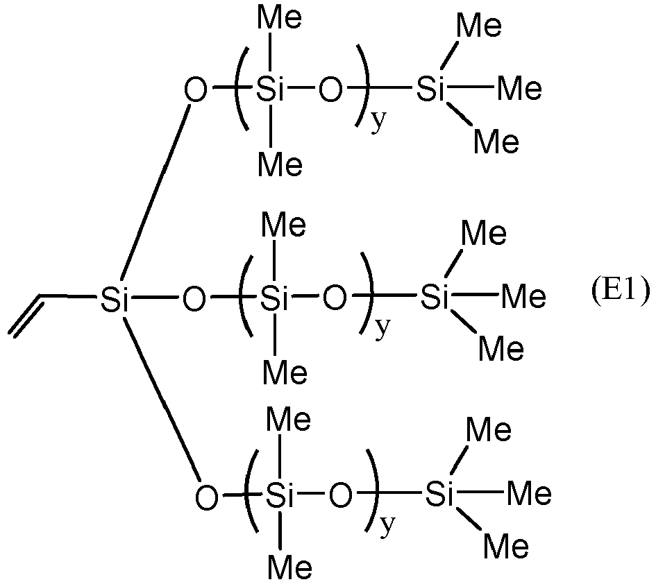
- A catalyst such as 1,3-diethenyl-1,1,3,3-tetramethyldisiloxane platinum complex is added into the mixed solution under nitrogen gas protection. The reaction is maintained for about 2
hours 25 °C and then for an additional 2 hours at 40 °C under mechanical stirring to yield a light yellow, transparent crosslinking agent having formula (E2):
- The crosslinking agent is then reacted with a prepolymer to form a separation layer. The particular prepolymer is a methyl-terminated vinylmethylsiloxane-octylmethylsiloxane-dimethylsiloxane terpolymer having a molecular weight of 10,000 Dalton to 12,000 Dalton and containing 3% to 5% vinylmethylsiloxane monomers, based on the total number of monomers other than the terminal monomers. Thus, the prepolymer has formula (E3), where R1 is octyl; p is from 0.35 to 0.40, m is from 0.03 to 0.05, and d + p + m =1:

- To form a separation layer, the crosslinking agent and a prepolymer are dissolved in an organic solvent such as chloroform or hexane under mechanical stirring to form a homogeneous solution. A catalyst such as 1,3-diethenyl-1,1,3,3-tetramethyldisiloxane platinum complex is added slowly into the solution, followed by stirring for 5 minutes to 30 minutes at 25 °C. The obtained solution is then degassed and prepared for coating.
- The composite membrane is fabricated by casting the separation layer solution onto a microporous polymer support such as polyacrylonitrile (with molecular weight cut-off (MWCO) of 150k), polyvinylidene fluoride (MWCO 75k to 250k), or polyether sulfone (MWCO 10k to 20k) at 25 °C. The resulting composite membrane is dried at 25 °C overnight to remove solvent. The composite membrane is then crosslinked in an oven at 50 °C to 100 °C for 24 hours to 72 hours, particularly from 60 °C to 75 °C for about 48 hours.
-
Composite Membrane 2 includes the polymer material ofFIG. 5 , where R1 is octyl, on a microporous polymer support. The polymer material ofFIG. 5 where R1 is octyl is prepared by the same method as described forComposite Membrane 1 in Example 1, except that the crosslinking agent is formed by reacting the vinyl T-structured polymer of formula (E1) with a methylhydrosiloxane-dimethylsiloxane copolymer according to formula (E4), where k is from 0.01 to 0.55, having a viscosity from 0.01 Pa·s (10 cP) to 8 Pa·s (8,000 cP):
- In the reaction mixture of the vinyl T-structured polymer with the methylhydrosiloxane-dimethylsiloxane copolymer, the vinyl groups of the vinyl T-structured polymer replaces the hydrogen atoms of the methylhydrosiloxane monomers to form Si-C-C-Si linkages. To enable the crosslinking agent to be further polymerized with the vinylmethylsiloxane-octylmethylsiloxane-dimethylsiloxane terpolymer, the vinyl T-structured polymer is added to the initial reaction mixture with the methylhydrosiloxane-dimethylsiloxane copolymer in an amount that results in reaction of fewer than all methylhydrosiloxane monomers of the methylhydrosiloxane-dimethylsiloxane copolymer with the vinyl T-structured polymer. Thus, the crosslinking agent for preparing
Composite Membrane 2 has formula (E5), where n is the same as in the methylhydrosiloxane-dimethylsiloxane copolymer of formula (E4), and b equals k of the copolymer of formula (E4) minus q.
- The crosslinking agent is then reacted with the prepolymer vinylmethylsiloxane-octylmethylsiloxane-dimethylsiloxane terpolymer, as previously described in Example 1, to form a separation layer solution. The separation layer solution is then cast onto a microporous polymer support, dried, and crosslinked. In the final reaction that results in the polymer material of Composite Membrane 2 (
FIG. 5 , R1 = octyl), vinyl groups of the prepolymer react with the remaining hydrogen atoms of the methylhydrosiloxane monomers of the crosslinking agent to form additional Si-C-C-Si linkages. - Characterizations and comparative data with regard to a composite membrane prepared according to the foregoing procedure are provided in Example 9.
-
Composite Membrane 3 includes the polymer material ofFIG. 6 on a microporous polymer support, specifically where R7 is methyl, groups ―OR2 are methoxy, and groups R2 bonded directly to silicon atoms are ethyl. The polymer material ofComposite Membrane 3 is prepared by first modifying a prepolymer according to formula (E3) to incorporate additional functionalities including Si-C-C-Si units, then addition curing the modified prepolymer with a crosslinking agent. - To modify the prepolymer, a polymer according to formula (E3), where p is from 0.35 to 0.40 and m is from 0.03 to 0.05, is dissolved in an organic solvent such as chloroform or hexane under vigorous mechanical stirring. To the dissolved prepolymer solution, a trialkylsilane such as triethylsilane, a trialkoxysilane such as trimethoxysilane, or a combination of a trialkylsilane and a trialkoysilane, may be added at a molar amount that results in reaction of the silanes with fewer than all of the monomers of the prepolymer that have vinyl groups. For example, if the prepolymer includes 3% to 5% vinyl monomers based on the total number of monomers in the prepolymer, the silanes may be added at an amount that results in from 1% to 99% of the vinyl monomers being unreacted after the modification.
- A catalyst such as 1,3-diethenyl-1,1,3,3-tetramethyldisiloxane platinum complex is added into the mixed solution under nitrogen gas protection. The reaction is maintained for about 2
hours 25 °C and then for an additional 2 hours at 40 °C under mechanical stirring to yield a modified prepolymer having formula (E6), where w and x are greater than or equal to zero, provided w + x is greater than zero; w + a + x equals m of the polymer according to formula (E3); and d and p are the same values as the corresponding values in the polymer according to formula (E3).
- A separation solution is then prepared by dissolving the modified prepolymer in an organic solvent such as chloroform or hexane under vigorous mechanical stirring and adding a crosslinking agent according to formula (E7), where R7 is methyl, subscript n is from 0.01 to 0.99, and subscript b is from 0.01 to 0.55 or from 0.01 to 0.10 or from 0.01 to 0.05:

- The crosslinking agent may be added in an appropriate molar amount such that the number of available methylhydrosiloxane monomer units (subscript b) of the crosslinking agent in solution is equal to the number of unreacted methylvinylsiloxane monomer units (subscript a in formula (E6)) of the prepolymer in solution. The crosslinking agent may have a viscosity ranging from 0.025 Pa·s (25 cP) to 8 Pa·s (8,000 cP). The solution containing the dissolved prepolymer and the dissolved crosslinking agent is stirred for about 5 minutes to 30 minutes at 25 °C then is degassed to prepare for coating. A catalyst such as 1,3-diethenyl-1,1,3,3-tetramethyldisiloxane platinum complex is added slowly into the solution, followed by stirring for 5 minutes to 30 minutes at 25 °C. The obtained separation layer solution is then degassed and prepared for coating.
- The separation layer solution is cast onto a microporous polymer support, dried, and crosslinked, as described in Example 1. In the final reaction that results in the polymer material of
Composite Membrane 3, vinyl groups of the prepolymer react with the hydrogen atoms of the methylhydrosiloxane monomers of the crosslinking agent to form Si―C―C―Si linkages in addition to those formed from adding the functional groups to form the modified prepolymer. -
Composite Membrane 4 includes the polymer material ofFIG. 6 on a microporous polymer support, specifically where R7 is octyl, where groups ―OR2 are methoxy, and where groups R2 bonded directly to silicon atoms are ethyl. The polymer material andComposite Membrane 4 are prepared in a manner identical to that ofComposite Membrane 3 described in Example 3, except that the crosslinking agent is a methylhydrosiloxane-octylmethylsiloxane copolymer according to formula (E7) where R7 is octyl, where subscript n is from 0.01 to 0.99, and where subscript b is from 0.15 to 0.50, or from 0.20 to 0.40, or from 0.25 to 0.30. The crosslinking agent may have a viscosity of 0.03 Pa·s (30 cP) to 0.06 Pa·s (60 cP). -
Composite Membrane 5 includes the polymer material ofFIG. 6 on a microporous polymer support, specifically where R7 is phenyl, groups ―OR2 are methoxy, and groups R2 bonded directly to silicon atoms are ethyl. The polymer material andComposite Membrane 5 are prepared in a manner identical to that ofComposite Membrane 3 described in Example 3, except that the crosslinking agent is a methylhydrosiloxane-methylphenylsiloxane copolymer according to formula (E7) where R7 is phenyl, subscript n is from 0.01 to 0.99, and subscript b is from 0.30 to 0.60 or from 0.40 to 0.55 or from 0.45 to 0.50. The crosslinking agent may have a viscosity of 0.075 Pa·s (75 cP) to 0.11 Pa·s (110 cP). -
Composite Membrane 6 includes the polymer material ofFIG. 7 on a microporous polymer support. The polymer material ofComposite Membrane 6 is prepared by first modifying a prepolymer according to formula (E3) to incorporate additional functionalities including Si-C-C-Si units having hydrolysable groups, then hydrolyzing and crosslinking the modified prepolymer without adding an additional crosslinking agent. - To modify the prepolymer, a polymer according to formula (E3), where p is from 0.35 to 0.40 and m is from 0.03 to 0.05, is dissolved in an organic solvent such as chloroform or hexane under vigorous mechanical stirring. To the dissolved prepolymer solution, a trialkoxysilane such as trimethoxysilane and, optionally in addition to the trialkoxylsilane, a trialkylsilane such as triethylsilane, may be added at a molar amount that results in reaction of the silanes with all of the monomers of the prepolymer that have vinyl groups. Thus, the modified prepolymer may have formula (E6), as in Example 3, but where the subscript a representing unreacted vinyl groups is zero.
- The modified prepolymer is then reacted with water in the presence of an appropriate catalyst such as dibutyltin dilaurate (DBTDL), for example, or with a silanol compound, to replace silicon-bonded methoxy groups with hydroxyl groups with liberation of one molecule of methanol for every converted methoxy group. The result of either reaction is a separation layer solution containing a polymer having formula (E8):

- The separation layer solution is cast onto a microporous polymer support, dried, and crosslinked, as described in Example 1. During crosslinking, a hydroxy group from each of two molecules of the compound of formula (E8) react with release of one molecule of water to form an intermolecular crosslink, one of which is illustrated as formula (E9):

- When the polymer compound is fully crosslinked, all of the hydroxyl groups remaining in the structure of formula (E9) will have reacted with hydroxyl groups of other polymer molecules.
- Characterizations and data with regard to a composite membrane prepared according to the foregoing procedure are provided in Example 10.
-
Composite Membrane 7 includes the polymer material ofFIG. 8 on a microporous polymer support. The polymer material ofComposite Membrane 7 is prepared by first dissolving in organic solvent the copolymer having formula (E10), where m is from 0.01 to 0.55 and x is less than m. The copolymer having formula (E10) is prepared in the same manner as the crosslinking agent of formula (E5) in Example 2 of this specification.
- The copolymer solution is then mixed with a sufficient molar amount of an ω-alkenyltrialkoxysilane of the formula CH2=CH(CH2)zSi(OR)3 (where z is an integer from 0 to 10 and R is an alkyl such as methyl or ethyl) to react with the remaining unreacted hydrogen atoms of the methylhydrosiloxane monomers represented by the subscript "m - x" in formula (E10). To form the polymer material of
FIG. 8 , the ω-alkenyltrialkoxysilane is an allyltrialkoxysilane such as, for example, allyltrimethoxysilane having the formula =CH2CH(CH2)Si(OCH3)3. Alternatively, a silane having shorter ω-alkenyl group such as vinyl (z is zero) or a longer alkenyl group where z is an integer from 2 to 10. In general, the length of the ω-alkenyl group of the ω-alkenyltrialkoxysilane determines the length of crosslinking monomers present in the polymer material ofComposite Membrane 7. A catalyst such as 1,3-diethenyl-1,1,3,3-tetramethyldisiloxane platinum complex is added slowly into the solution, followed by stirring for 5 minutes to 30 minutes at 25 °C. - In the reaction product of the crosslinking agent having formula (E10) and allyltrimethoxysilane, the hydrogen atoms of the methylhydrosiloxane monomers of the copolymer are replaced with trimethoxysilyl-terminated groups ―(CH2)3Si(OCH3)3. The separation layer solution is prepared by hydrolyzing this reaction product using a mild catalyst such as acetic acid to form a crosslinkable compound. By the hydrolysis, the trimethoxysilyl-terminated groups of the initial reaction product are converted to trihydroxysilyl-terminated groups ―(CH2)3Si(OH)3 in the crosslinkable compound.
- The separation layer solution containing the crosslinkable compound is cast onto a microporous polymer support, dried, and crosslinked, as described in Example 1. During crosslinking, the hydroxyl groups of trihydroxysilyl-terminated groups ―(CH2)3Si(OH)3 from each of two molecules of the crosslinkable compound react with release of one molecule of water to form an intermolecular crosslink.
- As bases for comparison, conventional composite membranes of poly(dimethylsiloxane) (PDMS) and poly(octylmethylsiloxane) (POMS) were prepared using polymers from commercial sources. The PDMS polymer was prepared from a two-part kit of a vinyl-terminated dimethylsiloxane oligomer (RTV615A, from Momentive Performance Materials) and an RTV615B crosslinker. The POMS polymer was prepared from a vinylmethylsiloxane-octylmethylsiloxane oligomer available from Gelest and the RTV615B crosslinker. Separation layer solutions of the PDMS and the POMS were prepared by dissolving polymer in an organic solvent such as chloroform or hexane and casting the separation layer solution onto a microporous polymer support and drying at 25 °C overnight to remove solvent.
- A supported membrane (Composite Membrane 2) having the polymer material of
FIG. 5 was prepared according to the procedure of Example 2 of this disclosure using polyacrylonitrile and non-woven poly(ethylene terephthalate) as the support. The supported films had uniform separation layer thicknesses of from 0.5 µm to 50 µm, uniform microporous support layer thicknesses of 30 µm to 60 µm, and non-woven structural support layer thickness of 100 µm to 250 µm. The supported membrane was characterized to determine permeability of the supported membrane to propane (C3H8) and butane (C4H10) at various pressures and temperatures, and to determine ratios of propane to methane (CH4) ideal selectivity and butane to methane ideal selectivity. - It should be understood that polymer membranes separate components of a gas or vapor mixture because the components permeate the membrane at different rates. The permeability of a polymer membrane material for a gas, P [in units Barrer, where 1 Barrer = 10-10 (cm3 STP·cm)/(cm2·s·cmHg)], is the rate at which that gas moves through a standard thickness [1 cm] of the membrane under a standard driving force (a pressure difference of 1 cmHg). A measure of the ability of a membrane to separate two gases is the selectivity, α, defined as the ratio of the gas permeabilities, P1/P2. Selectivity can also be expressed as:

- The ideal selectivity of a polymer material is established by measuring the permeabilities with pure gas or vapor samples, then calculating the ratio. The actual selectivity obtained in a real separation process is established by making permeation measurements with gas mixtures. Both high permeability and high selectivity are desirable, because a higher permeability decreases the size of membrane necessary to treat a given amount of gas, while higher selectivity results in a more highly purified product.
- To determine the effects of feed pressure on C3H8 permeability and on C4H10 permeability in the conventional PDMS membrane, the conventional POMS membrane, and
Composite Membrane 2 were tested using a custom designed constant volume gas permeation cell. A membrane is placed in the cell such that it forms a barrier between two halves of the cell: namely the upstream and the downstream. The upstream and downstream are both evacuated to degas the membrane. Then the upstream is pressurized with the desired gas at the desired pressure. The permeability of the gas is calculated by measuring the increase in downstream pressure over time (dp/dt) and using Equation 1:
- In
Equation 1, P is the permeability, v is the volume of the downstream chamber, l is the membrane thickness, R is the ideal gas constant, T is the absolute temperature, SA is the surface area of the membrane, and p is the upstream pressure. By performing this permeation test with each gas of interest, ideal selectivities are calculated. - To determine the ideal selectivity ratios C3H8/CH4 and C4H10/CH4 in the conventional PDMS membrane, the conventional POMS membrane, and
Composite Membrane 2 at a particular pressure and temperature, the ratio of permeabilities is calculated for a given gas pair (C3H8/CH4 or C4H10/CH4) at the same pressure and temperature. - The effect of feed pressure on C3H8 permeability of
Composite Membrane 2, PDMS, and POMS was measured at 25 °C, over a feed pressure range of 200 kPa (2.0 bar) to 700 kPa (7.0 bar). The data are summarized inFIG. 9 . The C3H8 permeability generally increased with increased feed pressure. At all feed pressures, theComposite Membrane 2 was more permeable to C3H8 than were both the PDMS membrane and the PMOS membrane. For example, at 200 kPa (2.0 bar) feed pressure,Composite Membrane 2 had a C3H8 permeability of about 1.87 x 10⁻¹² (mol·m)/(m2·s·Pa) (5,584 Barrer), compared to about 9.38 x 10⁻¹³ and 9.72 x 10⁻¹³ (mol·m)/(m2·s·Pa) (2,800 and 2,900 Barrer) for both PDMS and POMS, respectively. At a feed pressure of 700 kPa (7.0 bar),Composite Membrane 2 had a C3H8 permeability of about 6.50 x 10⁻¹² (mol·m)/(m2·s·Pa) (19,400 Barrer), compared to about 1.91 x 10⁻¹² (mol·m)/(m2·s·Pa) (5,700 Barrer) for POMS and 1.57 × 10⁻¹² (4,700 Barrer) for PDMS. - The effect of feed pressure on C3H8/CH4 ideal selectivity in
Composite Membrane 2, PDMS, and POMS was measured at 25 °C, over a feed pressure range of 200 kPa (2.0 bar) to 700 kPa (7.0 bar). The data are summarized inFIG. 10 . At all feed pressures tested, theComposite Membrane 2 had greater C3H8/CH4 ideal selectivity than both the PDMS membrane and the POMS membrane. The C3H8/CH4 ideal selectivity of all membranes increased with increasing feed pressure, with the increase being most pronounced forComposite Membrane 2. For example, at feed pressure 200 kPa (2.0 bar),Composite Membrane 2 had a C3H8/CH4 ideal selectivity of about 9.4, which increased by about 171% to about 25 at 700 kPa (7.0 bar). In comparison, the corresponding increase for POMS was about 117% [8.0 at 200 kPa (2.0 bar) and 17.4 at 700 kPa (7.0 bar)], and the corresponding increase for PDMS was about 95% [6.4 at 200 kPa (2.0 bar) and 12.4 at 700 kPa (7.0 bar)]. - The effect of feed pressure on C4H10 permeability of
Composite Membrane 2, PDMS, and POMS was measured at 25 °C, over a feed pressure range of 48.3 kPa (7 psi) to 206.8 kPa (30 psi). The data are summarized inFIG. 11 . The C4H10 permeability generally increased with increased feed pressure, similar to the trend observed with C3H8. At all feed pressures, theComposite Membrane 2 was more permeable to C4H10 than were both the PDMS membrane and the POMS membrane. - The effect of feed pressure on C4H10/CH4 ideal selectivity in
Composite Membrane 2, PDMS, and POMS was measured at 25 °C, over a feed pressure range of 48.3 kPa (7 psi) to 206.8 kPa (30 psi). The data are summarized in Table 1 and are graphed inFIG. 12 . At all feed pressures tested, theComposite Membrane 2 had greater C4H10/CH4 ideal selectivity at 25 °C than both the PDMS membrane and the POMS membrane. The C4H10/CH4 ideal selectivity of all membranes increased with increasing feed pressure, with the increase being most pronounced forComposite Membrane 2. For example, at feed pressure 48.3 kPa (7 psi),Composite Membrane 2 had a C4H10/CH4 ideal selectivity of about 21.9, which increased by about 344% to about 97.3 at 206.8 kPa (30 psi). In comparison, the corresponding increase for POMS was about 200% (19.3 at 48.3 kPa (7 psi) and 57.9 at 206.8 kPa (30 psi)), and the corresponding increase for PDMS was about 272% (9.6 at 48.3 kPa (7 psi) and 35.6 at 206.8 kPa (30 psi)).Table 1 Membrane Pressure in kPa (psi) C4H10/CH4 Ideal Selectivity PDMS (Comparative) 54.5 (7.9) 9.6 102.0 (14.8) 13.3 152.4 (22.1) 25.0 201.3 (29.2) 35.6 POMS (Comparative) 53.8 (7.8) 19.3 93.8 (13.6) 28.0 142.0 (20.6) 40.0 199.3 (28.9) 57.9 Composite Membrane 248. 3 (7.0) 21.9 96.5 (14.0) 28.4 144.8 (21.0) 62.1 206.8 (30.0) 97.3 - The C3H8/CH4 and C4H10/CH4 separation performances of
Composite Membrane 2, PDMS and POMS were investigated. InFIG. 13 , C3H8 permeability versus C3H8/CH4 ideal selectivity is plotted for PDMS, POMS, andComposite Membrane 2, measured at a temperature of 25 °C and at feed pressures of 344.7 kPa (50 psi) and 689.5 kPa (100 psi). At both 344.7 kPa (50 psi) and 689.5 kPa (100 psi), theComposite Membrane 2 was both more permeable to C3H8 than were PDMS and POMS, and theComposite Membrane 2 was more selective to C3H8 over CH4 than were PDMS and POMS. - In
FIG. 14 , C4H10 permeability versus C4H10/CH4 ideal selectivity is plotted for PDMS, POMS, andComposite Membrane 2, measured at a temperature of 25 °C and at feed pressures of 100 kPa (1 bar) and 200 kPa (2 bar). At both 100 kPa (1 bar) and 200 kPa (2 bar), theComposite Membrane 2 was both more permeable to C4H10 than were PDMS and POMS, and theComposite Membrane 2 was more selective to C4H10 over CH4 than were PDMS and POMS. - The effect of feed pressure on ideal selectivity at 25 °C of C3H8 over four gases typically found in natural gas sources (nitrogen, methane, hydrogen, and carbon dioxide) was evaluated for
Composite Membrane 2 over a range of feed pressure from 200 kPa (2.0 bar) to 7-700 kPa (7.0 bar), using the ideal selectivity measurement techniques described in Example 9 of this disclosure, where methane was replaced with nitrogen, hydrogen, or carbon dioxide for the applicable experiment. The data for these experiments are presented inFIG. 18 . At 25 °C and over the entire range of feed pressure evaluated, theComposite Membrane 2 consistently exhibited strong ideal selectivity to C3H8 over each of the four test gases. The increasing rate of ideal selectivity with pressure is observed to depend on the difference between the condensabilities or critical volumes of C3H8 and other gases. At the feed pressure of 690 kPa (6.9 bar),Composite Membrane 2 was approximately 3.6 times more permeable to C3H8 than to CO2, approximately 13.9 times more permeable to C3H8 than to H2, approximately 16.4 times more permeable to C3H8 than to CH4, and approximately 47.2 times more permeable to C3H8 than to N2. - A supported membrane (Composite Membrane 6) having the polymer material of
FIG. 7 was prepared according to the procedure of Example 6 of this disclosure. The supported membrane was characterized to evaluate its FTIR spectrum before and after crosslinking, the effects of feed pressure on C3H8 permeability, the effects of the operating temperature on C3H8/CH4 ideal selectivity, and selectivity of C3H8 over various gases as a function of feed pressure. - Fourier-Transform infrared (FTIR) spectra were collected from samples of the polymer material of
Composite Membrane 6 before and after crosslinking. InFIG. 15 , the FTIR spectrum (B) of the material crosslinked for four hours at 70 °C overlays the FTIR spectrum (A) of polymer material before crosslinking. The crosslinked material was found to lack a peak at 2147 cm-1, attributable to Si-H stretching, and a peak at 905 cm-1 attributable to Si-H bending vibrations, thus indicating that the crosslinking agent (silane Si-H) had nearly completely reacted with the PDMS. It is believed that the FTIR spectra follow the consumption of the silane groups during the crosslinking process and thereby indicate the effect of the silane concentration in the crosslinking reaction. Thus, when the peak at 902 cm-1 disappears, it may be presumed that the crosslinking reaction is complete. - The effect of feed pressure on C3H8 permeability of
Composite Membrane 6 was measured at four temperatures (25 °C, 35 °C, 52 °C, and 85 °C) over the feed pressure range of 200 kPa (2.0 bar) to 750 kPa (7.5 bar), following the measurement procedure described in Example 9. The data are summarized inFIG. 16 . Increased temperatures correspond with decreased solubility coefficients in condensable gases such as C3H8, resulting in a significant increase in C3H8 permeability at low temperature. But for non-condensable gases such as methane and nitrogen, decreasing the temperature caused permeability to decrease. Therefore, membrane C3H8/CH4 selectivity increases dramatically with a decrease of feed temperature. Similarly, the C3H8 permeability of PDMS control membranes were tested at the same conditions [temperature: 25 °C, 35 °C, 52 °C, and 85 °C) over the feed pressure range of 200 kPa (2.0 bar) to 750 kPa (7.5 bar)]. The change of C3H8 relative permeability (Pp /P2bar) with the increase of the applied C3H8 feed pressure at different feed temperatures was studied both forComposite Membrane 6 and PDMS control. Results showedComposite Membrane 6 to have a greater resistance to swelling than the PDMS control. - The effect of operating temperature on C3H8/CH4 ideal selectivity of
Composite Membrane 6 at a constant feed pressure of 689.5 kPa (100 pounds per square inch) (6.89 bar) was evaluated by measuring C3H8/CH4 ideal selectivity at four temperatures (25 °C, 35 °C, 52 °C, and 85 °C), following the measurement procedure described in Example 9. The data are presented inFIG. 17 . The C3H8/CH4 ideal selectivity ofComposite Membrane 6 was found to decrease from about 10.5 at 25 °C to about 2.8 at 85 °C. -
Composite Membrane 8 includes the polymer material ofFIG. 19 , where R1 is octyl and R7 is hydrogen, on a microporous polymer support. The polymer material ofFIG. 19 , where R1 is octyl and R7 is hydrogen, is prepared from a prepolymer according to formula (E3) (see Example 1), where R1 is octyl; p is from 0.35 to 0.40, m is from 0.03 to 0.05, and d + p + m =1. The prepolymer is dissolved in organic solvent and reacted in the presence of a catalyst with a crosslinking agent according to formula (E7) (see Example 3), where R7 is hydrogen, n is 0.5, and b is 0.5. A separation layer solution of the resulting polymer is then cast onto a microporous polymer support, dried, and crosslinked, as described in Example 1. - An
exemplary Composite Membrane 8 was prepared by the foregoing method with a crosslinking agent having a weight-average molecular weight of 1400 Dalton to 2400 Dalton. Characterization data for theexemplary Composite Membrane 8 are provided in Example 21. -
Composite Membrane 9 includes the polymer material ofFIG. 19 , where R1 is octyl and R7 is methyl, on a microporous polymer support. The polymer material ofFIG. 19 , where R1 is octyl and R7 is methyl, is prepared from a prepolymer according to formula (E3) (see Example 1), where R1 is octyl; p is from 0.35 to 0.40, m is from 0.03 to 0.05, and d + p + m =1. The prepolymer is dissolved in organic solvent and reacted in the presence of a catalyst with a crosslinking agent according to formula (E7) (see Example 3), where R7 is methyl, n is from 0.005 to 0.55, and b is from 0.45 to 0.995. A separation layer solution of the resulting polymer is then cast onto a microporous polymer support, dried, and crosslinked, as described in Example 1. - An
exemplary Composite Membrane 9 was prepared by the foregoing method with a crosslinking agent having a weight-average molecular weight of 900 Dalton to 65,000 Dalton. Characterization data for theexemplary Composite Membrane 9 are provided in Example 21. -
Composite Membrane 10 includes the polymer material ofFIG. 19 , where R1 is octyl and R7 is octyl, on a microporous polymer support. The polymer material ofFIG. 19 , where R1 is octyl and R7 is octyl, is prepared from a prepolymer according to formula (E3) (see Example 1), where R1 is octyl; p is from 0.35 to 0.40, m is from 0.03 to 0.05, and d + p + m =1. The prepolymer is dissolved in organic solvent and reacted in the presence of a catalyst with a crosslinking agent according to formula (E7) (see Example 3), where R7 is octyl, n is from 0.25 to 0.30, and b is from 0.70 to 0.75. A separation layer solution of the resulting polymer is then cast onto a microporous polymer support, dried, and crosslinked, as described in Example 1. - An
exemplary Composite Membrane 10 was prepared by the foregoing method with a crosslinking agent having a weight-average molecular weight of 280 Dalton to 480 Dalton. Characterization data for theexemplary Composite Membrane 8 are provided in Example 21. - Composite Membrane 11 includes the polymer material of
FIG. 19 , where R1 is octyl and R7 is phenyl, on a microporous polymer support. The polymer material ofFIG. 19 , where R1 is octyl and R7 is phenyl, is prepared from a prepolymer according to formula (E3) (see Example 1), where R1 is octyl; p is from 0.35 to 0.40, m is from 0.03 to 0.05, and d + p + m =1. The prepolymer is dissolved in organic solvent and reacted in the presence of a catalyst with a crosslinking agent according to formula (E7) (see Example 3), where R7 is phenyl, n is from 0.45 to 0.50, and b is from 0.50 to 0.55. A separation layer solution of the resulting polymer is then cast onto a microporous polymer support, dried, and crosslinked, as described in Example 1. - An exemplary Composite Membrane 11 was prepared by the foregoing method with a crosslinking agent having a weight-average molecular weight of 160 Dalton to 170 Dalton. Characterization data for the exemplary Composite Membrane 11 are provided in Example 21.
- Composite Membrane 12 includes the polymer material of
FIG. 20 on a microporous support. The polymer material ofFIG. 19 is prepared from a prepolymer according to formula (E3) (see Example 1), where R1 is phenyl; p is from 0.35 to 0.40, m is from 0.03 to 0.05, and d + p + m =1. The prepolymer is dissolved in organic solvent and reacted in the presence of a catalyst with a hydride-terminated polymethylsiloxane crosslinking agent according to formula (E11) where y is an integer from 1 to 850, from 1 to 500, from 1 to 100, from 1 to 50, from 1 to 40, from 1 to 30, from 1 to 20, from 1 to 10, or from 1 to 5:
- A separation layer solution of the resulting polymer is then cast onto a microporous polymer support, dried, and crosslinked, as described in Example 1. In the polymer material of
FIG. 20 , crosslinking occurs at the crosslinking sites Z1, generally through the reaction of the hydride on the end of the crosslinking agent not already attached to a polysiloxane backbone with a vinyl group of a vinylmethylsiloxane monomer in a second polymer backbone. - An exemplary Composite Membrane 12 was prepared by the foregoing method with a prepolymer having a weight-average molecular weight of 2500 Dalton to 3000 Dalton and a crosslinking agent having a weight-average molecular weight of 400 Dalton to 63,000 Dalton. The reaction of the hydride-terminated polymethylsiloxane crosslinking agent according to formula (E11) with the prepolymer according to formula (E3) was considerably faster than the reaction of the crosslinking agent according to formula (E7) with the prepolymer according to formula (E3) in Example 14. It is believed that the greater reactivity of the hydride-terminated polymethylsiloxane crosslinking agent according to formula (E11) resulted in a polymer material of
FIG. 20 that was tougher and had a greater crosslinking density than that of the polymer material ofFIG. 19 (Example 14). -
Composite Membrane 13 includes the polymer material ofFIG. 19 , where R1 is phenyl and R7 is hydrogen, on a microporous polymer support. The polymer material ofFIG. 19 , where R1 is phenyl and R7 is hydrogen, is prepared from a prepolymer according to formula (E3) (see Example 1), where R1 is phenyl; p is from 0.35 to 0.40, m is from 0.03 to 0.05, and d + p + m =1. The prepolymer is dissolved in organic solvent and reacted in the presence of a catalyst with a crosslinking agent according to formula (E7) (see Example 3), where R7 is hydrogen, n is 0.50, and b is 0.50. A separation layer solution of the resulting polymer is then cast onto a microporous polymer support, dried, and crosslinked, as described in Example 1. - An
exemplary Composite Membrane 13 was prepared by the foregoing method with a prepolymer having a weight-average molecular weight of 2500 Dalton to 3000 Dalton and a crosslinking agent having a weight-average molecular weight of 14,000 Dalton to 24,000 Dalton. Characterization data for theexemplary Composite Membrane 13 are provided in Example 21. -
Composite Membrane 14 includes the polymer material ofFIG. 19 , where R1 is phenyl and R7 is methyl, on a microporous polymer support. The polymer material ofFIG. 19 , where R1 is phenyl and R7 is methyl, is prepared from a prepolymer according to formula (E3) (see Example 1), where R1 is phenyl; p is from 0.35 to 0.40, m is from 0.03 to 0.05, and d + p + m =1. The prepolymer is dissolved in organic solvent and reacted in the presence of a catalyst with a crosslinking agent according to formula (E7) (see Example 3), where R7 is methyl, n is from 0.005 to 0.55, and b is from 0.45 to 0.995. A separation layer solution of the resulting polymer is then cast onto a microporous polymer support, dried, and crosslinked, as described in Example 1. - An
exemplary Composite Membrane 14 was prepared by the foregoing method with a prepolymer having a weight-average molecular weight of 2500 Dalton to 3000 Dalton and a crosslinking agent having a weight-average molecular weight of 900 Dalton to 65,000 Dalton. -
Composite Membrane 15 includes the polymer material ofFIG. 19 , where R1 is phenyl and R7 is octyl, on a microporous polymer support. The polymer material ofFIG. 19 , where R1 is phenyl and R7 is octyl, is prepared from a prepolymer according to formula (E3) (see Example 1), where R1 is phenyl; p is from 0.35 to 0.40, m is from 0.03 to 0.05, and d + p + m =1. The prepolymer is dissolved in organic solvent and reacted in the presence of a catalyst with a crosslinking agent according to formula (E7) (see Example 3), where R7 is octyl, n is from 0.25 to 0.30, and b is from 0.70 to 0.75. A separation layer solution of the resulting polymer is then cast onto a microporous polymer support, dried, and crosslinked, as described in Example 1. - An
exemplary Composite Membrane 15 was prepared by the foregoing method with a prepolymer having a weight-average molecular weight of 2500 Dalton to 3000 Dalton and a crosslinking agent having a weight-average molecular weight of 280 Dalton to 480 Dalton. - Composite Membrane 16 includes the polymer material of
FIG. 19 , where R1 is phenyl and R7 is phenyl, on a microporous polymer support. The polymer material ofFIG. 19 , where R1 is phenyl and R7 is phenyl, is prepared from a prepolymer according to formula (E3) (see Example 1), where R1 is phenyl; p is from 0.35 to 0.40, m is from 0.03 to 0.05, and d + p + m =1. The prepolymer is dissolved in organic solvent and reacted in the presence of a catalyst with a crosslinking agent according to formula (E7) (see Example 3), where R7 is phenyl, n is from 0.45 to 0.50, and b is from 0.50 to 0.55. A separation layer solution of the resulting polymer is then cast onto a microporous polymer support, dried, and crosslinked, as described in Example 1. - An
exemplary Composite Membrane 15 was prepared by the foregoing method with a prepolymer having a weight-average molecular weight of 2500 Dalton to 3000 Dalton and a crosslinking agent having a weight-average molecular weight of 160 Dalton to 170 Dalton. - Composite Membrane 17 includes the polymer material of
FIG. 5 , where R1 is phenyl, on a microporous polymer support. The polymer material ofFIG. 5 where R1 is phenyl is prepared by the same method as described forComposite Membrane 2 in Example 2, except that to form the separation layer the crosslinking agent of formula (E5) is reacted with a prepolymer vinylmethylsiloxane-phenylmethylsiloxane-dimethylsiloxane terpolymer according to formula (E3), where R1 is phenyl, m is from 0.03 to 0.05, p is from 0.35 to 0.40, having a weight-average molecular weight of 2500 Dalton to 3000 Dalton. - An exemplary Composite Membrane 17 was prepared by the foregoing method with a prepolymer having a weight-average molecular weight of 2500 Dalton to 3000 Dalton. Characterization data for the exemplary Composite Membrane 17 are provided in Example 21.
- The C3H8 permeabilities and C3H8/CH4 ideal selectivities of
Composite Membranes 8―11, 13, and 17 and of the PDMS and POMS of Comparative Example 8 were measured at 25 °C, at a feed pressure of 344.7 kPa (50 psi) (3.4 bar) following the measurement procedure described in Example 9 of this disclosure. The C4H10 permeabilities and C4H10/CH4 ideal selectivities ofComposite Membranes 8―11, 13, and 17 were measured at 25 °C, at a feed pressure of 100 kPa (1 bar, 14.5 psi) following the measurement procedure described in Example 9 of this disclosure. The data from these experiments are summarized in Table 2.Table 2 Membrane C3H8 Permeability at 344.7 kPa (50 psi) in (mol·m)/(m2·s·Pa) (Barrer) C3H8/CH4 Ideal Selectivity at 344.7 kPa (50 psi) C4H10 Permeability at 100 kPa (1 bar) in (mol·m)/(m2·s·Pa) (Barrer) C4H10/CH4 Ideal Selectivity at 100 kPa (1 bar) PDMS (Comparative) 1.03 × 10⁻¹² (3074.6) 7.7 1.39 × 10⁻¹² (4144.3) 13.3 POMS (Comparative) 1.16 × 10⁻¹² (3465.8) 10.6 1.29 × 10⁻¹² (3852.8) 28.0 Composite Membrane 81.37 × 10⁻¹² (4092.4) 10.3 2.93 × 10⁻¹² (8750.2) 19.7 Composite Membrane 92.84 × 10⁻¹² (8478.6) 10.2 6.85 × 10⁻¹² (20449.2) 31.2 Composite Membrane 109.96 × 10⁻¹⁴ (297.3) 12.3 3.15 × 10⁻¹³ (940.1) 38.8 Composite Membrane 11 1.48 × 10⁻¹² (4403.9) 12.4 3.42 × 10⁻¹² (10215.7) 37.1 Composite Membrane 132.12 × 10⁻¹³ (632.7) 9.25 5.80 × 10⁻¹³ (1732.4) 25.5 Composite Membrane 17 3.27 × 10⁻¹³ (977.2) 12.8 2.77 × 10⁻¹² (8264.3) 47.9 - The effect of feed pressure on C3H8/CH4 ideal selectivity in
Composite Membrane 10 and Composite Membrane 17, PDMS, and POMS was measured at 25 °C, over a feed pressure range of 200 kPa (2.0 bar) to 700 kPa (7.0 bar). The data are summarized inFIG. 21 . At all feed pressures tested, the modified membranes had greater C3H8/CH4 ideal selectivity than that of both the PDMS membrane and the POMS membrane. The C3H8/CH4 ideal selectivity of all membranes increased with increasing feed pressure, with the increase being most pronounced forComposite Membrane 10 and Composite Membrane 17. For example, at feed pressure 200 kPa (2.0 bar),Composite Membrane 10 had a C3H8/CH4 ideal selectivity of about 9.3, which increased by about 245% to about 32 at 700 kPa (7.0 bar), while Composite Membrane 17 had a C3H8/CH4 ideal selectivity of about 9.3, which increased by about 127% to about 24 at 700 kPa (7.0 bar). In comparison, the corresponding increase for POMS was about 117% [8.0 at 200 kPa (2.0 bar) and 17.4 at 700 kPa (7.0 bar)], and the corresponding increase for PDMS was about 95% [6.4 at 200 kPa (2.0 bar) and 12.4 at 700 kPa (7.0 bar)].
Claims (9)
- A composite membrane comprising a polymer material that is selectively permeable to heavy hydrocarbons having three or more carbon atoms over methane, the polymer material comprising a first copolymer having a polysiloxane backbone according to formula (I):
M―O―(A1)d―(A2)p―(A3)m―M (I)
in which:each A1 is a dimethylsiloxyl monomer;each A2 is independently chosen from substituted methylsiloxyl monomers having formula (M1): each A3 is independently chosen from internal-network monomers having formula (M2):
 each Q is a crosslinking site Z1 to a second copolymer having a polysiloxane backbone according to formula (II):
M―O―(G1)n―(L)b―(G2)q―M (II)
in which:each G1 is independently chosen from monomers having formula (G1): where R7 is chosen from C1―C10 alkyl or C6―C10 aryl; and each G2 is independently chosen from internal-network monomers having formula (G2):
 each L is a linking monomer having formula (G3):
 the Z2 of at least one linking monomer L of the second copolymer is a crosslinking site to the first copolymer;subscripts n, b, and q represent molar fractions of randomly arranged monomers of the second copolymer; wherein:(A): n is from 0.45 to 0.99, b is from 0.01 to 0.5, q is from 0 to 0.05, and n + b + q = 1; or(B): n is from 0.005 to 0.55, b is from 0.45 to 0.995, q is 0, Z2 is the crosslinking site Z1 of the first copolymer, and n + b + q = 1;each R1 is independently chosen from a C5―C10 alkyl or phenyl;subscripts d, p, and m represent molar fractions of randomly arranged monomers A1, A2, and A3 in the polysiloxane backbone;d is from 0.30 to 0.79;p is from 0.20 to 0.50;m is from 0.01 to 0.20;
 each M in formula (I) and formula (II) is a terminal silyl group.
 - The composite membrane of claim 1, wherein the subscripts n, b and q represent molar fractions of randomly arranged monomers of the second copolymer wherein: (B) n is from 0.005 to 0.55, b is from 0.45 to 0.995, q is 0, Z2 is the crosslinking site Z1 of the first copolymer, and n + b + q = 1.
- The composite membrane of claim 1, wherein each R1 is octyl.
- The composite membrane of claim 1, further comprising a porous support layer and a base support that provide structural support to the polymer material, wherein the polymer material is coated onto a porous support layer, and the porous support layer is interposed between the polymer material and the base support; wherein optionally:- the base support is a nonwoven material; preferably wherein the nonwoven material is chosen from poly(ethylene terephthalate), cellulose acetates, polyethylene, polypropylene, poly(alkylamides); or poly(aryl amides); or- the porous support layer is a microporous material chosen from polyacrylonitriles, poly(vinylidene fluorides), polycarbonates, polyamides, cellulose acetates, polymer sulfones, polyether ketones, polyetherether ketones, or polyether sulfones.
- The composite membrane of claim 1, wherein:n is from 0.45 to 0.989, b is from 0.01 to 0.5, q is from 0.001 to 0.05,
 Z2 is the crosslinking site Z1 of the first copolymer;each R1 is octyl or phenyl; andeach G1 is a dimethylsiloxyl monomer.
 - The composite membrane of claim 1, wherein:subscripts n, b, and q are as defined in option (B); andeach R1 is C5-C10 alkyl, octyl, or phenyl.
- The composite membrane of claim 6, wherein each R7 is methyl, or wherein each R7 is octyl and n is from 0.25 to 0.3; or wherein each R7 is phenyl and n is from 0.45 to 0.50.
- A system for removing heavy hydrocarbons from natural gas, the system comprising:a separator unit comprising an inlet, a retentate outlet, and a permeate outlet;a source of natural gas in fluidic communication with the inlet of the separator unit;at least one composite membrane according to claim 1 configured within the separator unit to prevent a flow of fluids from the inlet to the permeate outlet without first passing through the at least one composite membrane and to permit the flow of fluids to proceed from the inlet to the retentate outlet without passing through the at least one composite membrane;a retentate collector in fluidic communication with the retentate outlet of the separator unit;a permeate collector in fluidic communication with the permeate outlet of the separator unit; preferably wherein the polymer material of the composite membrane is coated onto a porous support layer, and the porous support layer is interposed between the polymer material and a nonwoven material, and more preferably wherein the nonwoven material is poly(ethylene terephthalate) and the porous support layer is chosen from polyacrylonitrile, poly(vinylidene fluoride), or polyether sulfone.
- A method for removing heavy hydrocarbons having at least three carbon atoms from a natural gas stream containing methane and an initial volume fraction of the heavy hydrocarbons, the method comprising:introducing the natural gas stream at a feed pressure, preferably at a feed pressure from 1 bar to 10 bar, into a separator unit comprising an inlet, a retentate outlet, a permeate outlet, and at least one composite membrane according to claim 1, configured within the separator unit to prevent a flow of fluids from the inlet to the permeate outlet without first passing through the at least one composite membrane and to permit the flow of fluids to proceed from the inlet to the retentate outlet without passing through the at least one composite membrane, preferably wherein the separator unit is at a separation temperature of from 20 °C to 100 °C; andcollecting at least one of:a retentate from the retentate outlet, the retentate having a reduced volume fraction of the heavy hydrocarbons, the reduced volume fraction being less than the initial volume fraction; ora permeate from the permeate outlet, the permeate having an increased volume fraction of the heavy hydrocarbons, the increased volume fraction being greater than the initial volume fraction.
Applications Claiming Priority (2)
| Application Number | Priority Date | Filing Date | Title |
|---|---|---|---|
| US15/428,662 US10293301B2 (en) | 2017-02-09 | 2017-02-09 | Modified siloxane composite membranes for heavy hydrocarbon recovery |
| PCT/US2018/017189 WO2018148258A1 (en) | 2017-02-09 | 2018-02-07 | Modified siloxane composite membranes for heavy hydrocarbon recovery |
Publications (2)
| Publication Number | Publication Date |
|---|---|
| EP3579954A1 EP3579954A1 (en) | 2019-12-18 |
| EP3579954B1 true EP3579954B1 (en) | 2021-11-24 |
Family
ID=61283303
Family Applications (1)
| Application Number | Title | Priority Date | Filing Date |
|---|---|---|---|
| EP18707463.8A Active EP3579954B1 (en) | 2017-02-09 | 2018-02-07 | Modified siloxane composite membranes for heavy hydrocarbon recovery |
Country Status (8)
| Country | Link |
|---|---|
| US (1) | US10293301B2 (en) |
| EP (1) | EP3579954B1 (en) |
| JP (1) | JP7091351B2 (en) |
| KR (1) | KR20190111127A (en) |
| CN (1) | CN110267730B (en) |
| SA (1) | SA519402449B1 (en) |
| SG (1) | SG11201907197UA (en) |
| WO (1) | WO2018148258A1 (en) |
Families Citing this family (7)
| Publication number | Priority date | Publication date | Assignee | Title |
|---|---|---|---|---|
| KR102357385B1 (en) * | 2018-12-31 | 2022-01-28 | 한국에너지기술연구원 | Multi-layered composite membrane for unreacted methane recovery after direct conversion of methane and methane utilization system by using the same |
| CN111530307B (en) * | 2020-05-07 | 2021-04-16 | 吉林大学 | Preparation method of while-drilling sensor silicon rubber gas-liquid separation membrane |
| CN117427505A (en) * | 2022-07-13 | 2024-01-23 | 中国石油化工股份有限公司 | Composite separation membrane and its preparation method and application, gas separation method |
| US12516192B2 (en) * | 2022-11-22 | 2026-01-06 | Saudi Arabian Oil Company | Modified siloxane rubbery composite membranes for C3+ heavy hydrocarbon separation |
| JP2024170939A (en) * | 2023-05-29 | 2024-12-11 | セイコーエプソン株式会社 | Gas separation membrane and method for producing gas separation membrane |
| JP2025140099A (en) * | 2024-03-13 | 2025-09-29 | セイコーエプソン株式会社 | Gas separation membrane |
| CN119926188B (en) * | 2025-01-21 | 2025-10-28 | 江苏久膜高科技股份有限公司 | Preparation method of oxygen-enriched composite membrane, oxygen-enriched composite membrane and application |
Citations (1)
| Publication number | Priority date | Publication date | Assignee | Title |
|---|---|---|---|---|
| CN102008909B (en) * | 2010-12-13 | 2012-10-10 | 大连欧科膜技术工程有限公司 | Preparation method for gas separation composite membrane |
Family Cites Families (18)
| Publication number | Priority date | Publication date | Assignee | Title |
|---|---|---|---|---|
| JPS60161703A (en) * | 1984-01-30 | 1985-08-23 | Teijin Ltd | Gas permselective composite membrane |
| US4602922A (en) * | 1984-11-09 | 1986-07-29 | Research Foundation Of State University Of New York | Method of making membranes for gas separation and the composite membranes |
| JPS61129008A (en) * | 1984-11-28 | 1986-06-17 | Sanyo Chem Ind Ltd | Composite membrane for separating gas and its preparation |
| GB8521607D0 (en) * | 1985-08-30 | 1985-10-02 | Shell Int Research | Separation of solvents from hydrocarbons |
| WO1994009886A1 (en) * | 1992-11-04 | 1994-05-11 | Membrane Technology And Research, Inc. | Gas-separation process |
| US7645422B2 (en) | 2003-04-11 | 2010-01-12 | Therm-O-Disc, Incorporated | Vapor sensor and materials therefor |
| US7211637B2 (en) | 2004-06-03 | 2007-05-01 | Therm-O-Disc, Incorporated | Sterically hindered reagents for use in single component siloxane cure systems |
| WO2008118228A2 (en) * | 2006-12-05 | 2008-10-02 | Stonybrook Water Purification | Articles comprising a fibrous support |
| WO2009025900A2 (en) * | 2007-05-26 | 2009-02-26 | Stonybrook Water Purification | High flux fluid separation membranes comprising a cellulose or cellulose derivative layer |
| WO2011099587A1 (en) * | 2010-02-10 | 2011-08-18 | 富士フイルム株式会社 | Gas separation membrane, method for producing same, and gas separation method, module and separation apparatus each using the gas separation membrane |
| JP5742421B2 (en) * | 2011-04-21 | 2015-07-01 | 公立大学法人首都大学東京 | Room temperature curable organopolysiloxane composition and gas separation membrane |
| WO2014059132A2 (en) | 2012-10-12 | 2014-04-17 | Dow Corning Corporation | Membranes including polysiloxane-poly(alkylene oxide) copolymers and methods of using the same |
| JP6136952B2 (en) | 2013-02-28 | 2017-05-31 | 信越化学工業株式会社 | Thermally conductive composite silicone rubber sheet |
| JP2014176795A (en) | 2013-03-14 | 2014-09-25 | Fujifilm Corp | Gas separation composite membrane |
| US10525420B2 (en) * | 2013-03-15 | 2020-01-07 | The Board Of Regents Of The University Of Texas System | Compositions and methods for improving the anti-fouling properties of polyethersulfone membranes |
| JP2015051407A (en) | 2013-09-09 | 2015-03-19 | 富士フイルム株式会社 | Gas separation composite membrane, gas separation module, gas separation device and gas separation method |
| US10112150B2 (en) * | 2014-07-17 | 2018-10-30 | The Research Foundation For The State University Of New York | Porous graphene based composite membranes for nanofiltration, desalination, and pervaporation |
| US10569218B2 (en) * | 2016-11-17 | 2020-02-25 | Uop Llc | Multiple membrane separation process using glassy polymeric membrane and rubbery polymeric membrane |
-
2017
- 2017-02-09 US US15/428,662 patent/US10293301B2/en active Active
-
2018
- 2018-02-07 SG SG11201907197UA patent/SG11201907197UA/en unknown
- 2018-02-07 EP EP18707463.8A patent/EP3579954B1/en active Active
- 2018-02-07 JP JP2019542710A patent/JP7091351B2/en active Active
- 2018-02-07 CN CN201880010682.0A patent/CN110267730B/en active Active
- 2018-02-07 KR KR1020197026346A patent/KR20190111127A/en not_active Withdrawn
- 2018-02-07 WO PCT/US2018/017189 patent/WO2018148258A1/en not_active Ceased
-
2019
- 2019-08-18 SA SA519402449A patent/SA519402449B1/en unknown
Patent Citations (1)
| Publication number | Priority date | Publication date | Assignee | Title |
|---|---|---|---|---|
| CN102008909B (en) * | 2010-12-13 | 2012-10-10 | 大连欧科膜技术工程有限公司 | Preparation method for gas separation composite membrane |
Non-Patent Citations (1)
| Title |
|---|
| HUAXIN RAO ET AL: "Gas separation properties of siloxane/polydimethylsiloxane hybrid membrane containing fluorine", SEPARATION AND PURIFICATION TECHNOLOGY, ELSEVIER SCIENCE, AMSTERDAM, NL, vol. 78, no. 2, 16 January 2011 (2011-01-16), pages 132 - 137, XP028156389, ISSN: 1383-5866, [retrieved on 20110126], DOI: 10.1016/J.SEPPUR.2011.01.029 * |
Also Published As
| Publication number | Publication date |
|---|---|
| SA519402449B1 (en) | 2022-10-17 |
| JP7091351B2 (en) | 2022-06-27 |
| JP2020507459A (en) | 2020-03-12 |
| KR20190111127A (en) | 2019-10-01 |
| SG11201907197UA (en) | 2019-09-27 |
| WO2018148258A1 (en) | 2018-08-16 |
| CN110267730A (en) | 2019-09-20 |
| US20180221813A1 (en) | 2018-08-09 |
| EP3579954A1 (en) | 2019-12-18 |
| CN110267730B (en) | 2022-02-01 |
| US10293301B2 (en) | 2019-05-21 |
Similar Documents
| Publication | Publication Date | Title |
|---|---|---|
| US10293301B2 (en) | Modified siloxane composite membranes for heavy hydrocarbon recovery | |
| Rao et al. | Preparation and oxygen/nitrogen permeability of PDMS crosslinked membrane and PDMS/tetraethoxysilicone hybrid membrane | |
| JP6397000B2 (en) | Self-crosslinking and self-crosslinking aromatic polyimide membranes for separation | |
| CN106795180A (en) | The mixed substrate membrane containing nano-grade molecular sieve of the modified and prepared therefrom azide crosslinking of zeolite imidazole ester skeleton | |
| CN105792917A (en) | Asymmetric modified carbon molecular sieve hollow fiber membranes with improved permeability | |
| EP3820598B1 (en) | Fluorinated polytriazole membrane materials for gas separation technology | |
| Romero et al. | Synthesis of polyetherimide/silica hybrid membranes by the sol–gel process: influence of the reaction conditions on the membrane properties | |
| US20160001237A1 (en) | Asymmetrically porous membranes made of cross-linked thermoplastic silicone elastomer | |
| CN110382086B (en) | Carbon molecular sieve membrane for aggressive gas separation | |
| Semsarzadeh et al. | Structural and transport properties of polydimethylsiloxane based polyurethane/silica particles mixed matrix membranes for gas separation | |
| CN104822440A (en) | Blend polymeric membranes containing fluorinated ethylene-propylene polymers for gas separations | |
| Luo et al. | Improved permeability by incorporating polysiloxane in SBS block copolymers for CH4/N2 gas separation | |
| CN110099735A (en) | High-throughput crosslinking pyrogenic silica for separation enhances polysiloxane film | |
| Yang et al. | Significantly enhanced CH4 permeability base on poly (styrene-b-butadiene-b-styrene)-poly (dimethylsiloxane-co-methylhydrosiloxane) crosslinked membranes | |
| WO2006009520A1 (en) | Polyimide membranes | |
| Matsuyama et al. | Plasma polymerized membranes from organosilicon compounds for separation of oxygen over nitrogen | |
| Liu et al. | A new PDMS-b-PPO block copolymer membrane with novel non-perforated structure towards high flux for alcohol permselective pervaporation. | |
| CN110461450A (en) | Rubbery polymer membranes for separation | |
| US11667755B2 (en) | Siloxane hybrid membranes for enhanced natural gas liquid recovery | |
| Wang et al. | Synthesis, in-situ membrane preparation, and good gas permselectivity of insoluble poly (substituted acetylene) s loosely cross-linked with short and soft siloxane and silanol linkages | |
| KR100637416B1 (en) | Hybrid membrane for separating volatile organic compounds produced by using modified silica nanoparticles and PDMS, manufacturing method and use thereof | |
| Rao et al. | Gas separation properties of siloxane/polydimethylsiloxane hybrid membrane containing fluorine | |
| Grushevenko et al. | The Effect of the Type and Concentration of the Crosslinking Diene on the Gas Transport Properties of Membranes Based on Polyoctylmethylsiloxane | |
| Borisov et al. | Sorption selective membranes based on polydimethylsildimethylene-and polydimethylsiltrimethylenedimethylsiloxane | |
| US12516192B2 (en) | Modified siloxane rubbery composite membranes for C3+ heavy hydrocarbon separation |
Legal Events
| Date | Code | Title | Description |
|---|---|---|---|
| STAA | Information on the status of an ep patent application or granted ep patent |
Free format text: STATUS: UNKNOWN |
|
| STAA | Information on the status of an ep patent application or granted ep patent |
Free format text: STATUS: THE INTERNATIONAL PUBLICATION HAS BEEN MADE |
|
| PUAI | Public reference made under article 153(3) epc to a published international application that has entered the european phase |
Free format text: ORIGINAL CODE: 0009012 |
|
| STAA | Information on the status of an ep patent application or granted ep patent |
Free format text: STATUS: REQUEST FOR EXAMINATION WAS MADE |
|
| 17P | Request for examination filed |
Effective date: 20190826 |
|
| AK | Designated contracting states |
Kind code of ref document: A1 Designated state(s): AL AT BE BG CH CY CZ DE DK EE ES FI FR GB GR HR HU IE IS IT LI LT LU LV MC MK MT NL NO PL PT RO RS SE SI SK SM TR |
|
| AX | Request for extension of the european patent |
Extension state: BA ME |
|
| DAV | Request for validation of the european patent (deleted) | ||
| DAX | Request for extension of the european patent (deleted) | ||
| STAA | Information on the status of an ep patent application or granted ep patent |
Free format text: STATUS: EXAMINATION IS IN PROGRESS |
|
| 17Q | First examination report despatched |
Effective date: 20200605 |
|
| GRAP | Despatch of communication of intention to grant a patent |
Free format text: ORIGINAL CODE: EPIDOSNIGR1 |
|
| STAA | Information on the status of an ep patent application or granted ep patent |
Free format text: STATUS: GRANT OF PATENT IS INTENDED |
|
| INTG | Intention to grant announced |
Effective date: 20210707 |
|
| RIN1 | Information on inventor provided before grant (corrected) |
Inventor name: TAMMANA, VEERA VENKATA R. Inventor name: HARRIGAN, DANIEL Inventor name: YANG, JOHN Inventor name: VAIDYA, MILIND M. |
|
| GRAS | Grant fee paid |
Free format text: ORIGINAL CODE: EPIDOSNIGR3 |
|
| GRAA | (expected) grant |
Free format text: ORIGINAL CODE: 0009210 |
|
| STAA | Information on the status of an ep patent application or granted ep patent |
Free format text: STATUS: THE PATENT HAS BEEN GRANTED |
|
| AK | Designated contracting states |
Kind code of ref document: B1 Designated state(s): AL AT BE BG CH CY CZ DE DK EE ES FI FR GB GR HR HU IE IS IT LI LT LU LV MC MK MT NL NO PL PT RO RS SE SI SK SM TR |
|
| REG | Reference to a national code |
Ref country code: GB Ref legal event code: FG4D |
|
| REG | Reference to a national code |
Ref country code: AT Ref legal event code: REF Ref document number: 1449424 Country of ref document: AT Kind code of ref document: T Effective date: 20211215 |
|
| REG | Reference to a national code |
Ref country code: DE Ref legal event code: R096 Ref document number: 602018027123 Country of ref document: DE |
|
| REG | Reference to a national code |
Ref country code: IE Ref legal event code: FG4D |
|
| REG | Reference to a national code |
Ref country code: NL Ref legal event code: FP |
|
| REG | Reference to a national code |
Ref country code: LT Ref legal event code: MG9D |
|
| REG | Reference to a national code |
Ref country code: AT Ref legal event code: MK05 Ref document number: 1449424 Country of ref document: AT Kind code of ref document: T Effective date: 20211124 |
|
| PG25 | Lapsed in a contracting state [announced via postgrant information from national office to epo] |
Ref country code: RS Free format text: LAPSE BECAUSE OF FAILURE TO SUBMIT A TRANSLATION OF THE DESCRIPTION OR TO PAY THE FEE WITHIN THE PRESCRIBED TIME-LIMIT Effective date: 20211124 Ref country code: LT Free format text: LAPSE BECAUSE OF FAILURE TO SUBMIT A TRANSLATION OF THE DESCRIPTION OR TO PAY THE FEE WITHIN THE PRESCRIBED TIME-LIMIT Effective date: 20211124 Ref country code: FI Free format text: LAPSE BECAUSE OF FAILURE TO SUBMIT A TRANSLATION OF THE DESCRIPTION OR TO PAY THE FEE WITHIN THE PRESCRIBED TIME-LIMIT Effective date: 20211124 Ref country code: BG Free format text: LAPSE BECAUSE OF FAILURE TO SUBMIT A TRANSLATION OF THE DESCRIPTION OR TO PAY THE FEE WITHIN THE PRESCRIBED TIME-LIMIT Effective date: 20220224 Ref country code: AT Free format text: LAPSE BECAUSE OF FAILURE TO SUBMIT A TRANSLATION OF THE DESCRIPTION OR TO PAY THE FEE WITHIN THE PRESCRIBED TIME-LIMIT Effective date: 20211124 |
|
| PG25 | Lapsed in a contracting state [announced via postgrant information from national office to epo] |
Ref country code: IS Free format text: LAPSE BECAUSE OF FAILURE TO SUBMIT A TRANSLATION OF THE DESCRIPTION OR TO PAY THE FEE WITHIN THE PRESCRIBED TIME-LIMIT Effective date: 20220324 Ref country code: SE Free format text: LAPSE BECAUSE OF FAILURE TO SUBMIT A TRANSLATION OF THE DESCRIPTION OR TO PAY THE FEE WITHIN THE PRESCRIBED TIME-LIMIT Effective date: 20211124 Ref country code: PT Free format text: LAPSE BECAUSE OF FAILURE TO SUBMIT A TRANSLATION OF THE DESCRIPTION OR TO PAY THE FEE WITHIN THE PRESCRIBED TIME-LIMIT Effective date: 20220324 Ref country code: PL Free format text: LAPSE BECAUSE OF FAILURE TO SUBMIT A TRANSLATION OF THE DESCRIPTION OR TO PAY THE FEE WITHIN THE PRESCRIBED TIME-LIMIT Effective date: 20211124 Ref country code: NO Free format text: LAPSE BECAUSE OF FAILURE TO SUBMIT A TRANSLATION OF THE DESCRIPTION OR TO PAY THE FEE WITHIN THE PRESCRIBED TIME-LIMIT Effective date: 20220224 Ref country code: LV Free format text: LAPSE BECAUSE OF FAILURE TO SUBMIT A TRANSLATION OF THE DESCRIPTION OR TO PAY THE FEE WITHIN THE PRESCRIBED TIME-LIMIT Effective date: 20211124 Ref country code: HR Free format text: LAPSE BECAUSE OF FAILURE TO SUBMIT A TRANSLATION OF THE DESCRIPTION OR TO PAY THE FEE WITHIN THE PRESCRIBED TIME-LIMIT Effective date: 20211124 Ref country code: GR Free format text: LAPSE BECAUSE OF FAILURE TO SUBMIT A TRANSLATION OF THE DESCRIPTION OR TO PAY THE FEE WITHIN THE PRESCRIBED TIME-LIMIT Effective date: 20220225 Ref country code: ES Free format text: LAPSE BECAUSE OF FAILURE TO SUBMIT A TRANSLATION OF THE DESCRIPTION OR TO PAY THE FEE WITHIN THE PRESCRIBED TIME-LIMIT Effective date: 20211124 |
|
| PG25 | Lapsed in a contracting state [announced via postgrant information from national office to epo] |
Ref country code: SM Free format text: LAPSE BECAUSE OF FAILURE TO SUBMIT A TRANSLATION OF THE DESCRIPTION OR TO PAY THE FEE WITHIN THE PRESCRIBED TIME-LIMIT Effective date: 20211124 Ref country code: SK Free format text: LAPSE BECAUSE OF FAILURE TO SUBMIT A TRANSLATION OF THE DESCRIPTION OR TO PAY THE FEE WITHIN THE PRESCRIBED TIME-LIMIT Effective date: 20211124 Ref country code: RO Free format text: LAPSE BECAUSE OF FAILURE TO SUBMIT A TRANSLATION OF THE DESCRIPTION OR TO PAY THE FEE WITHIN THE PRESCRIBED TIME-LIMIT Effective date: 20211124 Ref country code: EE Free format text: LAPSE BECAUSE OF FAILURE TO SUBMIT A TRANSLATION OF THE DESCRIPTION OR TO PAY THE FEE WITHIN THE PRESCRIBED TIME-LIMIT Effective date: 20211124 Ref country code: DK Free format text: LAPSE BECAUSE OF FAILURE TO SUBMIT A TRANSLATION OF THE DESCRIPTION OR TO PAY THE FEE WITHIN THE PRESCRIBED TIME-LIMIT Effective date: 20211124 Ref country code: CZ Free format text: LAPSE BECAUSE OF FAILURE TO SUBMIT A TRANSLATION OF THE DESCRIPTION OR TO PAY THE FEE WITHIN THE PRESCRIBED TIME-LIMIT Effective date: 20211124 |
|
| REG | Reference to a national code |
Ref country code: DE Ref legal event code: R097 Ref document number: 602018027123 Country of ref document: DE |
|
| PG25 | Lapsed in a contracting state [announced via postgrant information from national office to epo] |
Ref country code: MC Free format text: LAPSE BECAUSE OF FAILURE TO SUBMIT A TRANSLATION OF THE DESCRIPTION OR TO PAY THE FEE WITHIN THE PRESCRIBED TIME-LIMIT Effective date: 20211124 |
|
| PLBE | No opposition filed within time limit |
Free format text: ORIGINAL CODE: 0009261 |
|
| STAA | Information on the status of an ep patent application or granted ep patent |
Free format text: STATUS: NO OPPOSITION FILED WITHIN TIME LIMIT |
|
| REG | Reference to a national code |
Ref country code: CH Ref legal event code: PL |
|
| REG | Reference to a national code |
Ref country code: BE Ref legal event code: MM Effective date: 20220228 |
|
| GBPC | Gb: european patent ceased through non-payment of renewal fee |
Effective date: 20220224 |
|
| PG25 | Lapsed in a contracting state [announced via postgrant information from national office to epo] |
Ref country code: LU Free format text: LAPSE BECAUSE OF NON-PAYMENT OF DUE FEES Effective date: 20220207 Ref country code: AL Free format text: LAPSE BECAUSE OF FAILURE TO SUBMIT A TRANSLATION OF THE DESCRIPTION OR TO PAY THE FEE WITHIN THE PRESCRIBED TIME-LIMIT Effective date: 20211124 |
|
| 26N | No opposition filed |
Effective date: 20220825 |
|
| PG25 | Lapsed in a contracting state [announced via postgrant information from national office to epo] |
Ref country code: SI Free format text: LAPSE BECAUSE OF FAILURE TO SUBMIT A TRANSLATION OF THE DESCRIPTION OR TO PAY THE FEE WITHIN THE PRESCRIBED TIME-LIMIT Effective date: 20211124 |
|
| PG25 | Lapsed in a contracting state [announced via postgrant information from national office to epo] |
Ref country code: LI Free format text: LAPSE BECAUSE OF NON-PAYMENT OF DUE FEES Effective date: 20220228 Ref country code: IE Free format text: LAPSE BECAUSE OF NON-PAYMENT OF DUE FEES Effective date: 20220207 Ref country code: GB Free format text: LAPSE BECAUSE OF NON-PAYMENT OF DUE FEES Effective date: 20220224 Ref country code: CH Free format text: LAPSE BECAUSE OF NON-PAYMENT OF DUE FEES Effective date: 20220228 |
|
| PG25 | Lapsed in a contracting state [announced via postgrant information from national office to epo] |
Ref country code: BE Free format text: LAPSE BECAUSE OF NON-PAYMENT OF DUE FEES Effective date: 20220228 |
|
| PG25 | Lapsed in a contracting state [announced via postgrant information from national office to epo] |
Ref country code: IT Free format text: LAPSE BECAUSE OF FAILURE TO SUBMIT A TRANSLATION OF THE DESCRIPTION OR TO PAY THE FEE WITHIN THE PRESCRIBED TIME-LIMIT Effective date: 20211124 |
|
| P01 | Opt-out of the competence of the unified patent court (upc) registered |
Effective date: 20230514 |
|
| PG25 | Lapsed in a contracting state [announced via postgrant information from national office to epo] |
Ref country code: MK Free format text: LAPSE BECAUSE OF FAILURE TO SUBMIT A TRANSLATION OF THE DESCRIPTION OR TO PAY THE FEE WITHIN THE PRESCRIBED TIME-LIMIT Effective date: 20211124 Ref country code: CY Free format text: LAPSE BECAUSE OF FAILURE TO SUBMIT A TRANSLATION OF THE DESCRIPTION OR TO PAY THE FEE WITHIN THE PRESCRIBED TIME-LIMIT Effective date: 20211124 |
|
| PG25 | Lapsed in a contracting state [announced via postgrant information from national office to epo] |
Ref country code: HU Free format text: LAPSE BECAUSE OF FAILURE TO SUBMIT A TRANSLATION OF THE DESCRIPTION OR TO PAY THE FEE WITHIN THE PRESCRIBED TIME-LIMIT; INVALID AB INITIO Effective date: 20180207 |
|
| PG25 | Lapsed in a contracting state [announced via postgrant information from national office to epo] |
Ref country code: MT Free format text: LAPSE BECAUSE OF FAILURE TO SUBMIT A TRANSLATION OF THE DESCRIPTION OR TO PAY THE FEE WITHIN THE PRESCRIBED TIME-LIMIT Effective date: 20211124 |
|
| PGFP | Annual fee paid to national office [announced via postgrant information from national office to epo] |
Ref country code: NL Payment date: 20250121 Year of fee payment: 8 |
|
| PGFP | Annual fee paid to national office [announced via postgrant information from national office to epo] |
Ref country code: DE Payment date: 20250122 Year of fee payment: 8 |
|
| PGFP | Annual fee paid to national office [announced via postgrant information from national office to epo] |
Ref country code: FR Payment date: 20250122 Year of fee payment: 8 |
|
| PG25 | Lapsed in a contracting state [announced via postgrant information from national office to epo] |
Ref country code: TR Free format text: LAPSE BECAUSE OF FAILURE TO SUBMIT A TRANSLATION OF THE DESCRIPTION OR TO PAY THE FEE WITHIN THE PRESCRIBED TIME-LIMIT Effective date: 20211124 |