EP3579532A2 - Mobiles endgerät mit nähensensor und kamera - Google Patents
Mobiles endgerät mit nähensensor und kamera Download PDFInfo
- Publication number
- EP3579532A2 EP3579532A2 EP19178377.8A EP19178377A EP3579532A2 EP 3579532 A2 EP3579532 A2 EP 3579532A2 EP 19178377 A EP19178377 A EP 19178377A EP 3579532 A2 EP3579532 A2 EP 3579532A2
- Authority
- EP
- European Patent Office
- Prior art keywords
- electronic device
- feature points
- display screen
- infrared sensor
- environmental images
- Prior art date
- Legal status (The legal status is an assumption and is not a legal conclusion. Google has not performed a legal analysis and makes no representation as to the accuracy of the status listed.)
- Ceased
Links
Images






Classifications
-
- H—ELECTRICITY
- H04—ELECTRIC COMMUNICATION TECHNIQUE
- H04M—TELEPHONIC COMMUNICATION
- H04M1/00—Substation equipment, e.g. for use by subscribers
- H04M1/72—Mobile telephones; Cordless telephones, i.e. devices for establishing wireless links to base stations without route selection
- H04M1/724—User interfaces specially adapted for cordless or mobile telephones
- H04M1/72448—User interfaces specially adapted for cordless or mobile telephones with means for adapting the functionality of the device according to specific conditions
- H04M1/72454—User interfaces specially adapted for cordless or mobile telephones with means for adapting the functionality of the device according to specific conditions according to context-related or environment-related conditions
-
- G—PHYSICS
- G09—EDUCATION; CRYPTOGRAPHY; DISPLAY; ADVERTISING; SEALS
- G09G—ARRANGEMENTS OR CIRCUITS FOR CONTROL OF INDICATING DEVICES USING STATIC MEANS TO PRESENT VARIABLE INFORMATION
- G09G5/00—Control arrangements or circuits for visual indicators common to cathode-ray tube indicators and other visual indicators
- G09G5/36—Control arrangements or circuits for visual indicators common to cathode-ray tube indicators and other visual indicators characterised by the display of a graphic pattern, e.g. using an all-points-addressable [APA] memory
- G09G5/363—Graphics controllers
-
- G—PHYSICS
- G06—COMPUTING OR CALCULATING; COUNTING
- G06T—IMAGE DATA PROCESSING OR GENERATION, IN GENERAL
- G06T7/00—Image analysis
- G06T7/20—Analysis of motion
- G06T7/246—Analysis of motion using feature-based methods, e.g. the tracking of corners or segments
-
- G—PHYSICS
- G06—COMPUTING OR CALCULATING; COUNTING
- G06T—IMAGE DATA PROCESSING OR GENERATION, IN GENERAL
- G06T7/00—Image analysis
- G06T7/70—Determining position or orientation of objects or cameras
- G06T7/73—Determining position or orientation of objects or cameras using feature-based methods
-
- G—PHYSICS
- G09—EDUCATION; CRYPTOGRAPHY; DISPLAY; ADVERTISING; SEALS
- G09G—ARRANGEMENTS OR CIRCUITS FOR CONTROL OF INDICATING DEVICES USING STATIC MEANS TO PRESENT VARIABLE INFORMATION
- G09G2330/00—Aspects of power supply; Aspects of display protection and defect management
- G09G2330/02—Details of power systems and of start or stop of display operation
- G09G2330/021—Power management, e.g. power saving
-
- G—PHYSICS
- G09—EDUCATION; CRYPTOGRAPHY; DISPLAY; ADVERTISING; SEALS
- G09G—ARRANGEMENTS OR CIRCUITS FOR CONTROL OF INDICATING DEVICES USING STATIC MEANS TO PRESENT VARIABLE INFORMATION
- G09G2354/00—Aspects of interface with display user
-
- H—ELECTRICITY
- H04—ELECTRIC COMMUNICATION TECHNIQUE
- H04M—TELEPHONIC COMMUNICATION
- H04M2250/00—Details of telephonic subscriber devices
- H04M2250/12—Details of telephonic subscriber devices including a sensor for measuring a physical value, e.g. temperature or motion
-
- H—ELECTRICITY
- H04—ELECTRIC COMMUNICATION TECHNIQUE
- H04M—TELEPHONIC COMMUNICATION
- H04M2250/00—Details of telephonic subscriber devices
- H04M2250/52—Details of telephonic subscriber devices including functional features of a camera
Definitions
- the disclosure relates to the field of electronic technology, and more particularly, to a control method for an electronic device, control device, electronic device, computer storage medium and computer apparatus.
- the full screen has become a development trend of the mobile phone.
- infrared light emitted by the infrared sensor under the screen during operation is easy to cause electron migration of components within the display screen, thereby causing the display screen to partially flicker, and the user experience is relatively poor.
- exemplary embodiments of the disclosure provide a control method for an electronic device, a control device, an electronic device, a computer storage medium and a computer apparatus.
- the disclosure provides a control method for an electronic device, the electronic device comprising a transparent display screen comprising a display area and an infrared sensor which is disposed below the display area, and configured to emit infrared light and receive infrared light reflected by an object to detect a distance of the object to the electronic device, wherein the control method comprises:
- the disclosure provides a control device for an electronic device, the electronic device comprising a transparent display screen comprising a display area and an infrared sensor disposed below the display area, and configured to emit infrared light and receive infrared light reflected by an object to detect a distance of the object to the electronic device, wherein the control device comprises:
- the disclosure provides an electronic device, comprising:
- the disclosure provides one or more non-transitory computer readable storage medium containing computer executable instructions, wherein the computer executable instructions cause the processor to perform the above control method of the electronic device, when being executed by one or more processors.
- the control method, the control device, the electronic device, the computer readable storage medium and the computer apparatus of the embodiments of the disclosure capture the multi-frame environmental images through the camera module when the electronic device is in the state of incoming call.
- the plurality of feature points in the multi-frame environmental images have changed is detected, it indicates that the user approaches the electronic device and makes a call. Then, turn off the transparent display screen and turn on the infrared sensor, which can avoid the influence of the flicker of the infrared sensor on the transparent display screen.
- a control method, a control device 200, an electronic device 100, a computer readable storage medium and a computer apparatus 300 of the embodiments of the disclosure are described in detail below with reference to FIG. 1 to FIG. 16 .
- an embodiment of the disclosure provides a control method for the electronic device 100.
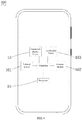
- the electronic device 100 comprises a transparent display screen 13 and an infrared sensor 161.
- the transparent display screen 13 comprises a display area 131.
- the infrared sensor 161 is disposed below the display area 131, and the infrared sensor 161 is configured to emit infrared light and receive infrared light reflected by an object to detect a distance of the object to the electronic device 100.
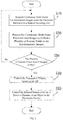
- the control method comprises steps:
- An embodiment of the disclosure provides a control device 200 for the electronic device 100.
- the control method for the electronic device 100 of the embodiments of the disclosure may be implemented by the control device 200 of the embodiments of the disclosure.
- the control device 200 comprises an acquisition module 21, a processing module 22, a determining module 23, and a control module 24.
- the step S10 may be implemented by the acquisition module 21.
- the step S20 may be implemented by the processing module 22.
- the step S30 may be implemented by the determining module 23.
- the step S40 and the step S50 may be implemented by the control module 24. That is to say, an acquisition module 21 is configured to acquire continuous multi-frame environmental images when the electronic device 100 is in a state of incoming call.
- the processing module 22 is configured to process in the continuous multi-frame environmental images to collect a plurality of feature points in the environmental images.
- the determining module 23 is further configured to determine whether the plurality of feature points in the continuous multi-frame environmental images have changed.
- the control module 24 is configured to, when the plurality of feature points have changed, control the transparent display screen 13 to be off and control the infrared sensor 161 to be on to detect a distance of an object to the electronic device 100.
- An embodiment of the disclosure provides an electronic device 100.
- the electronic device 100 comprises a transparent display screen 13, an infrared sensor 161, a camera module 162 and a processor 10.
- the transparent display screen 13 comprises a display area 131.
- the infrared sensor 161 is disposed below the display area 131, and the infrared sensor 161 is configured to emit infrared light and receive infrared light reflected by an object to detect a distance of the object to the electronic device 100.
- the camera module 162 is configured to capture images.
- the step S10, the step S20, the step S30, the step S40, and the step S50 may be implemented by the processor 10.
- the processor 10 may be configured to, when the electronic device 100 is in a state of incoming call, collect continuous multi-frame environmental images captured by the camera module 162; process the continuous multi-frame environmental images to collect a plurality of feature points in the environmental images; determine whether the plurality of feature points in the continuous multi-frame environmental images have changed; when the plurality of feature points have changed, control the transparent display screen13 to be off; and control the infrared sensor 161 to be on to detect a distance of an object to the electronic device 100.
- An embodiment of the disclosure provides a computer apparatus 300.
- the control device 200 may also be utilized in the computer apparatus 300.
- the computer apparatus 300 may be a mobile phone, a tablet computer, a notebook computer, a smart wristband, a smart watch, a smart helmet, a pair of smart eyeglass, a game machine, or the like.
- the electronic device 100 of the embodiments of the disclosure may also be one kind of the computer devices 300.
- An exemplary embodiment of the disclosure is illustrated by taking the electronic device 100 as a mobile phone as an example.
- An infrared sensor is generally disposed on the top of a mobile phone screen to determine a distance between the mobile phone and an obstacle and makes corresponding adjustments, thereby preventing a user from misoperation and saving power of the mobile phone.
- the infrared sensor 161 initiates the operation of distance detection.
- the infrared sensor 161 generates detection information by calculating the time of the transmitter emitting infrared light and the receiver receiving the reflected infrared light, or generates detection information based on the intensity of the transmitter emitting infrared light and the receiver receiving the reflected infrared light.
- the processor sends a corresponding instruction to the controller based on the detection information, and the controller controls the screen to be off based on the instruction.
- the processor sends a corresponding instruction to the controller again based on the detection information fed back by the infrared sensor 161, and the controller controls the screen to be on again based on the instruction.
- the infrared sensor is disposed below the area of the display screen.
- TFT Thin Film Transistor
- the infrared sensor Due to the photoelectric effect, with irradiation of the infrared light, electrons inside the TFT substrate are excited by infrared photons to generate a current, and the infrared sensor emits a pulse of infrared light, which causes the display screen to flicker.
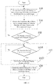
- the electronic device 100 first when being in a state of incoming call, collects continuous multi-frame environmental images; then process the continuous multi-frame environmental images to collect a plurality of feature points in the environmental images; and then determines whether the plurality of feature points in the continuous multi-frame environmental images have changed; controls the transparent display screen13 to be off when the plurality of feature points have changed; and control the infrared sensor 161 to be on to detect a distance of an object to the electronic device 100. In this way, after turning off the transparent display screen 13 and then turning on the infrared sensor 161, influence of the flicker of the infrared sensor 161 on the transparent display screen 13 can be avoided.
- the electronic device 100 is in a state of incoming call.
- the electronic device 100 acquires continuous multi-frame environmental images through the camera module 162, and then processes the continuous multi-frame environmental images to collect a plurality of feature points in the environmental images, wherein the plurality of feature points may be features of a human face such as facial contour features and eye contour features, and may also be features of background environmental objects, which are not restricted herein. Then determine whether the plurality of feature points in the continuous multi-frame environmental images have changed or whether the changes of the plurality of feature points exceed a predetermined value of changes.
- the control method of the embodiments of the disclosure is also applied to a scenario of the electronic device 100 being in a state of outgoing call. Specifically, it may be determined whether the electronic device 100 is in a state of outgoing call by detecting itself. When the electronic device 100 is calling out, captures multi-frame environmental images by the camera module 162. When that a plurality of feature points in the multi-frame environmental images have changed or the changes of the plurality of feature points exceed a predetermined value of changes is detected, which indicates the user brings the electronic device 100 close to the head to prepare a call. Then, turn off the transparent display screen 13 and turn on the infrared sensor 161, which can avoid the influence of the flicker of the infrared sensor 161 on the transparent display screen 13.
- scenario of incoming call and the scenario of outgoing call are merely exemplary, which the embodiments of the disclosure are not restricted thereto.
- scenarios of other voice call applications WeChat, QQ, Mi Chat, Yixin, etc.
- the electronic device 100 when the electronic device is not in the state of incoming call, the electronic device 100 maintains its original state and re-determines whether the transparent display screen 13 is on. After the electronic device is in the state of incoming call, when the plurality of feature points in the multi-frame environmental images have not changed or the changes of the plurality of feature points do not exceed the predetermined value of changes, the electronic device 100 maintains its original state, recaptures continuous multi-frame environmental images by using the camera module 162 and determines whether the plurality of feature points in the multi-frame environmental images have changed or the changes of the plurality of feature points exceed the predetermined value of changes.
- the step S30 of determining whether the plurality of feature points in the continuous multi-frame environmental images have changed comprises: S301: determining whether the positions of the plurality of feature points in a current frame environmental image have changed, compared with the plurality of feature points in a previous frame environmental image.
- the step S301 may be implemented by the determining module 23. That is to say, the determining module 23 is configured to determine whether the positions of the plurality of feature points in the current frame environmental image have changed, compared with the plurality of feature points in the previous frame environmental image.
- the processor 10 of the electronic device 100 may implement the step S301. That is to say, the processor 10 is configured to determine whether the positions of the plurality of feature points in a current frame environmental image have changed, compared with the plurality of feature points in the previous frame environmental image.
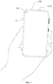
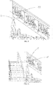
- the positions of the feature point I and the feature point II in the current environmental image in the image may be collected and recorded, referring to FIG. 10 , then are compared with the positions of the feature point I' and the feature point II' in the previous environmental image in the image. At this time, both of the positions of the feature point I and the feature point II in the current frame environmental image, relative to the positions of the feature point I' and the feature point II' in the previous frame environment image, have changed. It can be understood that the plurality of feature points in the image may be collected, which is not restricted herein.
- the electronic device 100 maintains its original state, recaptures the continuous multi-frame environmental images by using the camera module 162 and determine whether the positions of the plurality of feature points have changed.
- the step S40 of controlling the transparent display screen to be off comprises:
- the step S410 may be implemented by the determining module 23 and the step S420 may be implemented by the controlling module 24. That is to say, the determining module 23 is configured to determine whether the electronic device 100 is close to a user. The controlling module 24 is configured to control the transparent display screen 13 to be off when the electronic device 100 is close to the user.
- the processor 10 of the electronic device 100 may implement the step S410 and the step S420. That is to say, wherein the processor 10 is configured to determine whether the electronic device 100 is close to a user, and control the transparent display screen 13 to be off when the electronic device 100 is close to the user.
- the infrared sensor 161 may be turned on after turning off the transparent display screen 13. In this way, it is possible to avoid the influence of the flicker of the infrared sensor 161 on the transparent display screen 13.
- the user may need to perform other operations. At this time, the brightness of the transparent display screen 13 may be restored for the user to perform the next operation. If it is detected that the electronic device 100 is in a state of incoming call and is close to the user again, the transparent display screen 13 will be off again.
- the electronic device 100 maintains its original state and re-determines whether the electronic device 100 is close to the user.
- the step S410 of determining whether the electronic device is close to the user comprises:
- the control device 200 comprises a confirming module 25.
- the step S4111 may be implemented by the acquisition module 21.
- the step S4112 may be implemented by the determining module 23.
- the step S4113 may be implemented by the confirming module 25. That is to say, the acquisition module 21 is configured to acquire a state of motion of the electronic device 100.
- the determining module 23 is configured to determine whether the state of motion meets the predetermined state of motion.
- the confirming module 25 is configured to confirm the electronic device 100 is close to the user, when the state of motion meets the predetermined state of motion.
- the electronic device 100 comprises an acceleration sensor 163 for detecting the state of motion of the electronic device 100.
- the processor 10 is configured to acquire the state of motion of the electronic device 100 which is detected by the acceleration sensor 163, determine whether the state of motion meets the predetermined state of motion, and confirm that the electronic device 100 is close to the user when the state of motion meets the predetermined state of motion.
- the electronic device 100 may be determined whether the electronic device 100 is close to the user by detecting whether the electronic device 100 is lifted by the user. When that the electronic device 100 is lifted is detected, it may be confirmed that the electronic device 100 is close to the user. Detecting the motion of lifting of the user may be implemented by components such as a gyroscope and the acceleration sensor 163 of the electronic device 100.
- the gyroscope can measure the rotational angular velocity of the electronic device 100 when it is deflected and tilted.
- the acceleration sensor 163 can capture several typical modes of motion of the electronic device 100 such as shaking and tilting.
- the gyroscope and the acceleration sensor 163 may detect the state of motion of the electronic device 100, such as picking up, shaking and swinging. As described above, it may determine whether the user has an motion of lifting the electronic device 100 based on the detection data of the gyroscope or the acceleration sensor 163.
- the electronic device 100 when the state of motion of the electronic device 100 does not meet the predetermined state of motion, the electronic device 100 maintains its original state, reacquires the state of motion of the electronic device 100 and re-determines whether the state of motion of the electronic device 100 meets the predetermined state of motion.
- the manner of determining whether the electronic device 100 is close to the user in the step S410 may also be detected by the following embodiments.
- the step S410 of determining whether the electronic device is close to the user comprises:
- the step S4121 may be implemented by the determining module 23, the step S4122 may be implemented by the confirming module 25.
- the determining module 23 is configured to determine whether the continuous multi-frame environmental images include a human face.
- the confirming module 25 is configured to confirm the electronic device 100 is close to the user, when the continuous multi-frame environmental images include the human face.
- the processor 10 is configured to determine whether the continuous multi-frame environmental images include eyes of human, and determine that the electronic device 100 is close to the user when the eyes of human is included in the continuous multi-frame environment images.
- the continuous multi-frame environmental images include a human face. For example, whether the electronic device 100 is close to a user may be determined by identifying whether there is a region of human face in the continuous multi-frame environmental images and further identifying whether the region of human face includes a region of human ear. Specifically, referring to FIG. 14 , when it is identified that there is a region of side face of a user in the continuous multi-frame environmental images and there is a region of human ear in the region of side face, it may be determined that the user is already close to the electronic device 100.
- the detection of human face may be performed based on the preset portrait template, color, and the like in the database.
- the part connected to the human face may be determined as the portrait area.
- the specific embodiment is not restricted herein. For example, it may also determine a human face by matching with a portrait template. It can be understood that the identification of the region of human face may also be to identify whether there is a continuous color patch, and then identify the contour to determine a human face and a region of human ear.
- the camera module 162 may be a front-facing camera of the electronic device 100.
- the camera module 162 may acquire an RGB image of the environment in which the electronic device 100 is.
- the camera module 162 may also be a depth camera. In a depth image, depth data corresponding to features of nose, eyes, and ears in the region of human face are different. For example, when the human face is facing sideways the electronic device 100, in the captured depth image, the depth data corresponding to the nose may be large, while the depth data corresponding to the ears may be small.
- the number of the camera module 162 may be multiple, such as two front-facing cameras.
- the electronic device 100 further comprises a housing 20, wherein the housing 20 is configured to house components and subassemblies for protection, thereby avoiding external factors damaging these components directly.
- the housing 20 may be formed by machining an aluminum alloy by a CNC machine tool, or may be injection molded from a polycarbonate (PC) or a PC+ABS material.
- the transparent display screen 13 comprises an OLED display screen.
- the OLED display screen has good light transmittance, which is capable of transmitting visible light and infrared light well. Therefore, the OLED display screen will not affect the infrared sensor 161 to emit and receive infrared light at all in the case of exhibiting the effect of the content.
- the transparent display screen 13 may also be a Micro LED display screen, wherein the Micro LED display screen also has good light transmittance for visible light and infrared light.
- these display screens are merely exemplary and the exemplary embodiments of the disclosure are not restricted herein.
- the electronic device 100 may comprise a transparent cover 11 and a transparent touch panel 12.
- the transparent cover 11 is formed on the transparent touch panel 12.
- the transparent touch panel 12 is disposed on the transparent display screen 13.
- the upper surface 131 of the transparent display screen 13 faces the transparent touch panel 12.
- Both the transparent cover 11 and the transparent touch panel 12 have a visible light transmittance and an infrared light transmittance of more than 90%.
- the transparent touch panel 12 is mainly configured to receive an input signal generated by a user touching the transparent touch panel 12 and transmit the input signal to a circuit board for data processing, thereby obtaining a specific position of the user's touch of the transparent touch panel 12.
- the In-Cell or On-Cell lamination technology may be used to laminate the transparent touch panel 12 and the transparent display panel 13, thereby effectively reducing weight of the display screen and overall thickness of the display screen.
- the transparent cover 11 is disposed on the transparent touch panel 12, which can effectively protect the transparent touch panel 12 and its internal structure and avoid external force damaging the transparent touch panel 12 and the transparent display screen 13.
- the transmittances of both the transparent cover 11 and the transparent touch panel 12 for visible light and infrared light are more than 90%, which not only facilitates the transparent display screen 13 to display effect of content well, but also facilitates the infrared sensor 161 disposed below the transparent display screen 13 to stably emit and receive infrared light, which ensures the normal operation of the infrared sensor 161.
- the electronic device 100 comprises a first coating layer 141 coated on the lower surface 132 and covering the infrared sensor 161.
- the first coating layer 141 is used to transmit infrared light and intercept visible light.
- the infrared sensor 161 is for transmitting and/or receiving infrared light transmitting though the first coating layer 141 and the transparent display screen 13.
- the first coating layer 141 is configured to transmit infrared light to ensure the normal operation of the infrared sensor 161.
- the first coating layer 141 intercepts visible light, so that the infrared sensor 161 cannot be seen when the electronic device 100 is viewed from outside.
- the orthographic projection of the infrared sensor 161 on the lower surface 132 is located within the orthographic projection of the first coating layer 141 on the lower surface 132.
- the installation of the infrared sensor 161 usually requires a reserved assembly gap, resulting in a gap between the infrared sensor 161 and other components, which allows visible light enters from the gap and occur light-leaking phenomenon.
- the area of the orthographic projection of the first coating layer 141 on the lower surface 132 is larger than the area of the orthographic projection of the infrared sensor 161 on the lower surface 132.
- the first coating layer 141 can be sufficiently shielded the infrared sensor 161 without influence on normal operation of the infrared sensor 161 and the infrared sensor 161 can have an effect of invisibility when the electronic device 100 is viewed from outside.
- the orthographic projection of the infrared sensor 161 on the lower surface 132 coincides with the first coating layer 141.
- an area of orthographic projection which the first coating layer 141 is projected onto the lower surface 132 may be equal to an area of orthographic projection which the infrared sensor 161 is projected on the lower surface 132.
- the first coating layer 141 can just block the infrared sensor 161 without influence on the normal operation of the infrared sensor 161, and the infrared sensor 161 can have an effect of invisibility when the electronic device being viewed from the direction toward and perpendicular to the upper surface 131 of the transparent display screen 13.
- the electronic device further comprises a light shading layer 17 disposed on the lower surface 132 and surrounds the infrared sensor 161.
- the area of orthographic projection which the first coating layer 141 is projected onto the lower surface 132 is equal to the area of orthographic projection which the infrared sensor 161 is projected onto the lower surface 132
- volume of space for placing the infrared sensor 161 is larger than volume of the infrared sensor 161 which leads to, when the electronic device 100 is viewed from external environment, the light-leaking phenomenon occurs around the space around the infrared sensor 161. Therefore, by setting the light shading layer 17 surrounding the infrared sensor 161, the gap between the infrared sensor 161 and the surrounding space is filled, which may avoid this light-leaking phenomenon.
- the light shading layer 17 may be a foam made of a black material, or may be other black foamed plastic or rubber. Of course, these materials are merely exemplary and exemplary embodiments of the disclosure are not restricted herein.
- the first coating layer 141 comprises an IR ink, wherein the IR ink has a light transmittance of more than 85% for infrared light, wherein the IR ink has a light transmittance of less than 6% for visible light, wherein the IR ink allows infrared light which has a wavelength of more than 850nm to transmit.
- the IR ink since the IR ink has a characteristic of low light transmittance for visible light, when the electronic device 100 is viewed from outside, the infrared sensor 161 disposed under the first coating layer 141 cannot be visually observed by the vision of human eyes. At the same time, the IR ink also has a characteristic of high transmittance for infrared light, and enables the infrared sensor 161 to stably emit and receive infrared light, thereby ensuring normal operation of the infrared sensor 161.
- the electronic device 100 also comprises a second coating layer 15 coated on the lower surface 132 and connected with the first coating layer 141.
- the first coating layer 141 is mainly configured to transmit infrared light and shield the infrared sensor 161.
- the cost of the IR ink used by the first coating layer 141 is higher than that of ordinary black ink, if the lower surface 132 is entirely coated with the IR ink will not be conducive to reducing the cost of production.
- the ordinary black ink can achieve a lower light transmittance for visible light than the IR ink can, and the effect of shielding is more prominent, which not only helps to reduce the cost of production, but also the effect of shielding is more in line with the process requirements.
- the second coating layer 15 comprises a black ink. Both light transmittances of the black ink for visible light and light transmittance of the black ink for infrared light are less than 3%.
- the black ink has a lower light transmittance for visible light than the IR ink has, and the effect of shielding is more obvious, which is more in line with the process requirements.
- the cost of the black ink is lower than that of the IR ink, which helps to reduce the cost of production.
- the electronic device 100 further comprises a cushioning layer 18 which covers the lower surface 132 and avoids the infrared sensor 161.
- the cushioning layer 18 is configured to mitigate the impact force and be shockproof to protect the transparent touch panel 12, the transparent display screen 13 and the internal structure thereof, thereby preventing the transparent display screen 13 from being damaged by effect of external impact.
- the cushioning layer 18 may be made of foam, foamed plastic, rubber or other soft materials. Of course, these cushioning materials are merely exemplary and the exemplary embodiments of the disclosure are not restricted herein.
- the infrared sensor 161 is avoided in the process of setting the cushioning layer 18 in order to prevent the cushioning layer 18 from shielding the infrared sensor 161, thereby preventing the infrared sensor 161 from being affected in the process of transmitting and receiving infrared light.
- the electronic device 100 further comprises a sheet of metal 19 which covers the cushioning layer 18 and avoids the infrared sensor 161.
- the sheet metal 19 is configured to shield electromagnetic interference and be grounded, and has a function of diffusing risen temperature.
- the sheet of metal 19 may be cut from a metal material such as copper foil or aluminum foil.
- these metal materials are merely exemplary and the exemplary embodiments of the disclosure are not restricted herein.
- the infrared sensor 161 is avoided in the process of setting the sheet of metal 19 in order to prevent the sheet of metal 19 from blocking the infrared sensor 161, thereby preventing the infrared sensor 161 from being affected in the process of transmitting and receiving infrared light.
- An embodiment of the disclosure also provides a computer readable storage medium.
- One or more non-transitory computer readable storage medium containing computer executable instructions when the computer executable instructions are executed by one or more processors, causes the processor 10 to execute any one of the above embodiments of the control method of the electronic device 100.
- the step S10 is performed: the electronic device, when being in a state of incoming call, collects continuous multi-frame environmental images; the step S20: process the continuous multi-frame environmental images to collect a plurality of feature points in the environmental images; the step S30: determine whether the plurality of feature points in the continuous multi-frame environmental images have changed; the step S40: control the transparent display screen to be off when the plurality of feature points have changed; and the step S50: control the infrared sensor to be on to detect a distance of an object to the electronic device.
- an embodiment of the disclosure also provides a computer apparatus 300.
- the computer apparatus 300 comprises a memory 32 and a processor 10.
- the memory 32 stores computer readable instructions.
- the processor 10 performs the control method for the electronic device 100 of any of the above embodiments when instructions are being performed by the processor 10.
- the step S10 is performed: the electronic device, when being in a state of incoming call, collects continuous multi-frame environmental images; the step S20: process the continuous multi-frame environmental images to collect a plurality of feature points in the environmental images; the step S30: determine whether the plurality of feature points in the continuous multi-frame environmental images have changed; the step S40: control the transparent display screen to be off when the plurality of feature points have changed; and the step S50: control the infrared sensor to be on to detect a distance of an object to the electronic device.
- FIG. 5 is a block diagram of internal modules of a computer apparatus 300 in an embodiment.
- the computer apparatus 300 comprises a processor 10 connected via a system bus 31, a memory 32 (e.g. a non-transitory computer storage medium), an internal memory 33, a transparent display screen 13, an input device 34, an infrared sensor 161, a camera module 162 and an acceleration sensor 163.
- the memory 32 of the computer apparatus 300 stores an operating system and computer readable instructions.
- the computer readable instructions can be executed by the processor 10 to implement the control method of any of the above embodiments.
- the processor 10 may be configured to provide computing and controlling capabilities to support the operation of the entire computer apparatus 300.
- the internal memory 33 of the computer apparatus 300 provides an environment for computer readable instructions in the memory 32 to be operated in.
- the transparent display screen 13 of the computer apparatus 300 may be an OLED display screen or a Micro LED display screen.
- the input device 34 may be a touch screen covered on the transparent display screen 13, or may also be a button, trackball or touch pad of the computer apparatus 300, or may also be an external keyboard, touch pad, mouse and so on.
- the computer apparatus 300 may be a mobile phone, a tablet computer, a notebook computer, or the like. It can be understood by those skilled in the art that the structure shown in FIG. 5 is merely a schematic diagram of partial structure related to the solution of the disclosure, and does not constitute a limitation of the computer device 300 to which the solution of the disclosure is applied.
- a specific computer device 300 may include more or fewer components than those shown in FIG. 5 , or combine some components, or have different arrangements of components.
Landscapes
- Engineering & Computer Science (AREA)
- Theoretical Computer Science (AREA)
- Physics & Mathematics (AREA)
- General Physics & Mathematics (AREA)
- Human Computer Interaction (AREA)
- Environmental & Geological Engineering (AREA)
- Computer Networks & Wireless Communication (AREA)
- Signal Processing (AREA)
- Computer Vision & Pattern Recognition (AREA)
- Multimedia (AREA)
- Computer Graphics (AREA)
- Computer Hardware Design (AREA)
- Telephone Function (AREA)
- Controls And Circuits For Display Device (AREA)
Applications Claiming Priority (1)
| Application Number | Priority Date | Filing Date | Title |
|---|---|---|---|
| CN201810573756.3A CN108833694B (zh) | 2018-06-06 | 2018-06-06 | 控制方法、控制装置、电子装置、计算机存储介质及设备 |
Publications (2)
| Publication Number | Publication Date |
|---|---|
| EP3579532A2 true EP3579532A2 (de) | 2019-12-11 |
| EP3579532A3 EP3579532A3 (de) | 2019-12-18 |
Family
ID=64143378
Family Applications (1)
| Application Number | Title | Priority Date | Filing Date |
|---|---|---|---|
| EP19178377.8A Ceased EP3579532A3 (de) | 2018-06-06 | 2019-06-05 | Mobiles endgerät mit nähensensor und kamera |
Country Status (4)
| Country | Link |
|---|---|
| US (1) | US10560568B2 (de) |
| EP (1) | EP3579532A3 (de) |
| CN (1) | CN108833694B (de) |
| WO (1) | WO2019233467A1 (de) |
Families Citing this family (8)
| Publication number | Priority date | Publication date | Assignee | Title |
|---|---|---|---|---|
| CN108833694B (zh) | 2018-06-06 | 2020-06-26 | Oppo广东移动通信有限公司 | 控制方法、控制装置、电子装置、计算机存储介质及设备 |
| EP4007244B1 (de) * | 2019-07-31 | 2024-07-24 | BOE Technology Group Co., Ltd. | Endgerät |
| CN110392163B (zh) * | 2019-07-31 | 2021-09-07 | 努比亚技术有限公司 | 熄屏控制方法、移动终端以及计算机可读存储介质 |
| US11662695B2 (en) * | 2019-10-11 | 2023-05-30 | Dell Products L.P. | Information handling system infrared proximity detection with distance reduction detection |
| US11663343B2 (en) | 2020-01-31 | 2023-05-30 | Dell Products L.P. | Information handling system adaptive user presence detection |
| US11513813B2 (en) | 2020-01-31 | 2022-11-29 | Dell Products L.P. | Information handling system notification presentation based upon user presence detection |
| US11869435B2 (en) * | 2020-05-25 | 2024-01-09 | Shar Kabushiki Kaisha | Display device and proximity sensor control method |
| CN215835423U (zh) * | 2021-08-18 | 2022-02-15 | 荣耀终端有限公司 | 电子设备 |
Citations (3)
| Publication number | Priority date | Publication date | Assignee | Title |
|---|---|---|---|---|
| CN106940633A (zh) * | 2017-03-06 | 2017-07-11 | 广东欧珀移动通信有限公司 | 显示屏状态控制方法及装置 |
| CN107566643A (zh) * | 2017-08-31 | 2018-01-09 | 广东欧珀移动通信有限公司 | 信息处理方法、装置、存储介质以及电子设备 |
| CN107948419A (zh) * | 2017-11-22 | 2018-04-20 | 广东欧珀移动通信有限公司 | 电子装置 |
Family Cites Families (23)
| Publication number | Priority date | Publication date | Assignee | Title |
|---|---|---|---|---|
| JP2004159028A (ja) | 2002-11-06 | 2004-06-03 | Hitachi Ltd | カメラ内蔵携帯電話機能付き情報処理端末 |
| US20120050189A1 (en) | 2010-08-31 | 2012-03-01 | Research In Motion Limited | System And Method To Integrate Ambient Light Sensor Data Into Infrared Proximity Detector Settings |
| KR101685991B1 (ko) | 2010-09-30 | 2016-12-13 | 엘지전자 주식회사 | 이동 단말기 및 이동 단말기의 제어 방법 |
| US20120225694A1 (en) * | 2010-10-01 | 2012-09-06 | Sanjiv Sirpal | Windows position control for phone applications |
| KR101780508B1 (ko) | 2011-10-14 | 2017-09-22 | 삼성전자주식회사 | 통화 시의 귀를 구별하기 위한 이동 단말 및 그 방법 |
| US20130308835A1 (en) | 2012-05-21 | 2013-11-21 | Motorola Mobility, Inc. | Mobile Communication Device with Image Recognition and Method of Operation Therefor |
| JP6170673B2 (ja) | 2012-12-27 | 2017-07-26 | 富士フイルム株式会社 | カラーフィルタ用組成物、赤外線透過フィルタ及びその製造方法、並びに赤外線センサー |
| CN103916935A (zh) | 2012-12-31 | 2014-07-09 | 赛龙通信技术(深圳)有限公司 | 一种移动终端背光控制系统及控制方法 |
| JP5459420B1 (ja) | 2013-01-31 | 2014-04-02 | 凸版印刷株式会社 | 液晶表示装置及びカラーフィルタ基板 |
| KR20140140891A (ko) | 2013-05-30 | 2014-12-10 | 삼성전자주식회사 | 터치스크린을 구비하는 전자 기기의 근접 센싱 기능 운용 방법 및 장치 |
| US9282399B2 (en) * | 2014-02-26 | 2016-03-08 | Qualcomm Incorporated | Listen to people you recognize |
| US10203762B2 (en) * | 2014-03-11 | 2019-02-12 | Magic Leap, Inc. | Methods and systems for creating virtual and augmented reality |
| US10852838B2 (en) * | 2014-06-14 | 2020-12-01 | Magic Leap, Inc. | Methods and systems for creating virtual and augmented reality |
| CN105744052A (zh) * | 2014-12-11 | 2016-07-06 | 富泰华工业(深圳)有限公司 | 来电铃声控制系统及方法 |
| CN105824398A (zh) * | 2015-01-04 | 2016-08-03 | 华为技术有限公司 | 一种来电处理方法及移动终端 |
| CN105025159B (zh) * | 2015-06-05 | 2018-04-17 | 广东欧珀移动通信有限公司 | 接近传感器调节方法及装置 |
| CN106934269A (zh) | 2017-04-12 | 2017-07-07 | 广东欧珀移动通信有限公司 | 虹膜解锁方法、虹膜识别显示方法及移动终端 |
| CN107483712A (zh) | 2017-06-27 | 2017-12-15 | 捷开通讯(深圳)有限公司 | 移动终端及其控制方法、存储装置 |
| CN107943345B (zh) * | 2017-11-22 | 2020-10-02 | Oppo广东移动通信有限公司 | 接近传感器的校准方法、装置、存储介质和电子设备 |
| CN107818753A (zh) * | 2017-11-22 | 2018-03-20 | 广东欧珀移动通信有限公司 | 屏幕亮度调整方法、装置、存储介质和电子设备 |
| CN107767835B (zh) * | 2017-11-22 | 2020-04-10 | Oppo广东移动通信有限公司 | 显示屏组件及电子设备 |
| CN107896286A (zh) * | 2017-12-28 | 2018-04-10 | 贵州财富之舟科技有限公司 | 控制屏幕亮灭的方法及装置 |
| CN108833694B (zh) | 2018-06-06 | 2020-06-26 | Oppo广东移动通信有限公司 | 控制方法、控制装置、电子装置、计算机存储介质及设备 |
-
2018
- 2018-06-06 CN CN201810573756.3A patent/CN108833694B/zh not_active Expired - Fee Related
-
2019
- 2019-06-02 US US16/429,017 patent/US10560568B2/en active Active
- 2019-06-05 EP EP19178377.8A patent/EP3579532A3/de not_active Ceased
- 2019-06-06 WO PCT/CN2019/090240 patent/WO2019233467A1/en not_active Ceased
Patent Citations (3)
| Publication number | Priority date | Publication date | Assignee | Title |
|---|---|---|---|---|
| CN106940633A (zh) * | 2017-03-06 | 2017-07-11 | 广东欧珀移动通信有限公司 | 显示屏状态控制方法及装置 |
| CN107566643A (zh) * | 2017-08-31 | 2018-01-09 | 广东欧珀移动通信有限公司 | 信息处理方法、装置、存储介质以及电子设备 |
| CN107948419A (zh) * | 2017-11-22 | 2018-04-20 | 广东欧珀移动通信有限公司 | 电子装置 |
Also Published As
| Publication number | Publication date |
|---|---|
| CN108833694B (zh) | 2020-06-26 |
| CN108833694A (zh) | 2018-11-16 |
| US20190379779A1 (en) | 2019-12-12 |
| WO2019233467A1 (en) | 2019-12-12 |
| EP3579532A3 (de) | 2019-12-18 |
| US10560568B2 (en) | 2020-02-11 |
Similar Documents
| Publication | Publication Date | Title |
|---|---|---|
| US10560568B2 (en) | Control method, control device and electronic device | |
| CN109040417B (zh) | 控制方法、控制装置、电子装置、存储介质和计算机设备 | |
| CN108521480B (zh) | 控制方法、控制装置、电子装置、计算机存储介质和设备 | |
| US11032411B2 (en) | Control method for electronic device, electronic device, computer readable storage medium | |
| CN108848259B (zh) | 控制方法、控制装置、电子装置、计算机存储介质及设备 | |
| CN108769354A (zh) | 控制方法、控制装置、电子装置、存储介质和计算机设备 | |
| CN108989490B (zh) | 控制方法、控制装置、电子装置、存储介质和计算机设备 | |
| CN108718349B (zh) | 控制方法、控制装置、电子装置、存储介质和计算机设备 | |
| CN108803947B (zh) | 控制方法、控制装置、电子装置、计算机存储介质及设备 | |
| CN108683751B (zh) | 控制方法、控制装置、电子装置、计算机存储介质及设备 | |
| CN108810271A (zh) | 控制方法、控制装置、电子装置、存储介质和计算机设备 | |
| CN108762584A (zh) | 显示控制方法、控制装置、电子装置、存储介质和设备 | |
| CN108769355A (zh) | 控制方法、控制装置、电子装置、存储介质和设备 | |
| CN108989544B (zh) | 控制方法、控制装置、电子装置、计算机存储介质及设备 | |
| HK1262484B (en) | Control method, control apparatus, electronic apparatus, computer storage medium and device | |
| HK1262484A1 (en) | Control method, control apparatus, electronic apparatus, computer storage medium and device | |
| CN108718358B (zh) | 控制方法、控制装置、电子装置、计算机存储介质及设备 | |
| CN108696630B (zh) | 控制方法、控制装置、电子装置、计算机存储介质及设备 | |
| CN108848243A (zh) | 控制方法、控制装置、电子装置、计算机存储介质及设备 | |
| CN108874483B (zh) | 控制方法、控制装置、电子装置、存储介质和计算机设备 | |
| CN108769359A (zh) | 控制方法、控制装置、电子装置、计算机存储介质及设备 | |
| HK1263203A1 (en) | Control method, control device, electronic device, storage medium and computer apparatus | |
| HK1262335A1 (en) | Control method, control device, electronic device, computer storage medium and equipment | |
| HK1262335B (en) | Control method, control device, electronic device, computer storage medium and equipment | |
| HK1263203B (zh) | 控制方法、控制装置、电子装置、存储介质和计算机设备 |
Legal Events
| Date | Code | Title | Description |
|---|---|---|---|
| PUAI | Public reference made under article 153(3) epc to a published international application that has entered the european phase |
Free format text: ORIGINAL CODE: 0009012 |
|
| STAA | Information on the status of an ep patent application or granted ep patent |
Free format text: STATUS: THE APPLICATION HAS BEEN PUBLISHED |
|
| PUAL | Search report despatched |
Free format text: ORIGINAL CODE: 0009013 |
|
| AK | Designated contracting states |
Kind code of ref document: A2 Designated state(s): AL AT BE BG CH CY CZ DE DK EE ES FI FR GB GR HR HU IE IS IT LI LT LU LV MC MK MT NL NO PL PT RO RS SE SI SK SM TR |
|
| AX | Request for extension of the european patent |
Extension state: BA ME |
|
| AK | Designated contracting states |
Kind code of ref document: A3 Designated state(s): AL AT BE BG CH CY CZ DE DK EE ES FI FR GB GR HR HU IE IS IT LI LT LU LV MC MK MT NL NO PL PT RO RS SE SI SK SM TR |
|
| AX | Request for extension of the european patent |
Extension state: BA ME |
|
| RIC1 | Information provided on ipc code assigned before grant |
Ipc: H04M 1/725 20060101AFI20191111BHEP Ipc: G09G 5/36 20060101ALI20191111BHEP |
|
| STAA | Information on the status of an ep patent application or granted ep patent |
Free format text: STATUS: REQUEST FOR EXAMINATION WAS MADE |
|
| 17P | Request for examination filed |
Effective date: 20200217 |
|
| RBV | Designated contracting states (corrected) |
Designated state(s): AL AT BE BG CH CY CZ DE DK EE ES FI FR GB GR HR HU IE IS IT LI LT LU LV MC MK MT NL NO PL PT RO RS SE SI SK SM TR |
|
| STAA | Information on the status of an ep patent application or granted ep patent |
Free format text: STATUS: EXAMINATION IS IN PROGRESS |
|
| 17Q | First examination report despatched |
Effective date: 20211018 |
|
| STAA | Information on the status of an ep patent application or granted ep patent |
Free format text: STATUS: THE APPLICATION HAS BEEN REFUSED |
|
| 18R | Application refused |
Effective date: 20241026 |