EP3579434A1 - Datenübertragungsverfahren, netzwerkvorrichtung und endgerätevorrichtung - Google Patents
Datenübertragungsverfahren, netzwerkvorrichtung und endgerätevorrichtung Download PDFInfo
- Publication number
- EP3579434A1 EP3579434A1 EP18772421.6A EP18772421A EP3579434A1 EP 3579434 A1 EP3579434 A1 EP 3579434A1 EP 18772421 A EP18772421 A EP 18772421A EP 3579434 A1 EP3579434 A1 EP 3579434A1
- Authority
- EP
- European Patent Office
- Prior art keywords
- dmrs port
- bit sequence
- cbg
- data bit
- data
- Prior art date
- Legal status (The legal status is an assumption and is not a legal conclusion. Google has not performed a legal analysis and makes no representation as to the accuracy of the status listed.)
- Granted
Links
- 238000000034 method Methods 0.000 title claims abstract description 116
- 230000005540 biological transmission Effects 0.000 title claims abstract description 36
- 230000006854 communication Effects 0.000 claims description 101
- 238000004891 communication Methods 0.000 claims description 100
- 238000013507 mapping Methods 0.000 claims description 97
- 238000000605 extraction Methods 0.000 claims description 55
- 239000010410 layer Substances 0.000 description 417
- 238000013461 design Methods 0.000 description 51
- 101100437508 Rhizobium radiobacter cbg-1 gene Proteins 0.000 description 29
- 101150091511 glb-1 gene Proteins 0.000 description 29
- 230000006870 function Effects 0.000 description 18
- 230000009286 beneficial effect Effects 0.000 description 16
- 238000010586 diagram Methods 0.000 description 16
- 238000012545 processing Methods 0.000 description 12
- 230000001427 coherent effect Effects 0.000 description 8
- 230000000694 effects Effects 0.000 description 8
- 238000005516 engineering process Methods 0.000 description 6
- 230000007774 longterm Effects 0.000 description 6
- 101000741965 Homo sapiens Inactive tyrosine-protein kinase PRAG1 Proteins 0.000 description 4
- 102100038659 Inactive tyrosine-protein kinase PRAG1 Human genes 0.000 description 4
- 230000001174 ascending effect Effects 0.000 description 4
- 238000010295 mobile communication Methods 0.000 description 4
- 238000004590 computer program Methods 0.000 description 3
- 230000008878 coupling Effects 0.000 description 3
- 238000010168 coupling process Methods 0.000 description 3
- 238000005859 coupling reaction Methods 0.000 description 3
- 230000011664 signaling Effects 0.000 description 3
- 239000003795 chemical substances by application Substances 0.000 description 2
- 125000004122 cyclic group Chemical group 0.000 description 2
- 230000000977 initiatory effect Effects 0.000 description 2
- 239000011229 interlayer Substances 0.000 description 2
- 230000010363 phase shift Effects 0.000 description 2
- 230000001413 cellular effect Effects 0.000 description 1
- 238000013500 data storage Methods 0.000 description 1
- 238000005259 measurement Methods 0.000 description 1
- 230000003287 optical effect Effects 0.000 description 1
- 239000013307 optical fiber Substances 0.000 description 1
- 238000013468 resource allocation Methods 0.000 description 1
- 239000004065 semiconductor Substances 0.000 description 1
- 239000007787 solid Substances 0.000 description 1
- 238000001228 spectrum Methods 0.000 description 1
Images


Classifications
-
- H—ELECTRICITY
- H04—ELECTRIC COMMUNICATION TECHNIQUE
- H04L—TRANSMISSION OF DIGITAL INFORMATION, e.g. TELEGRAPHIC COMMUNICATION
- H04L5/00—Arrangements affording multiple use of the transmission path
- H04L5/003—Arrangements for allocating sub-channels of the transmission path
- H04L5/0048—Allocation of pilot signals, i.e. of signals known to the receiver
-
- H—ELECTRICITY
- H04—ELECTRIC COMMUNICATION TECHNIQUE
- H04L—TRANSMISSION OF DIGITAL INFORMATION, e.g. TELEGRAPHIC COMMUNICATION
- H04L5/00—Arrangements affording multiple use of the transmission path
- H04L5/0001—Arrangements for dividing the transmission path
- H04L5/0014—Three-dimensional division
- H04L5/0023—Time-frequency-space
-
- H—ELECTRICITY
- H04—ELECTRIC COMMUNICATION TECHNIQUE
- H04B—TRANSMISSION
- H04B1/00—Details of transmission systems, not covered by a single one of groups H04B3/00 - H04B13/00; Details of transmission systems not characterised by the medium used for transmission
- H04B1/69—Spread spectrum techniques
- H04B1/707—Spread spectrum techniques using direct sequence modulation
- H04B1/7097—Interference-related aspects
- H04B1/711—Interference-related aspects the interference being multi-path interference
-
- H—ELECTRICITY
- H04—ELECTRIC COMMUNICATION TECHNIQUE
- H04J—MULTIPLEX COMMUNICATION
- H04J11/00—Orthogonal multiplex systems, e.g. using WALSH codes
- H04J11/0023—Interference mitigation or co-ordination
- H04J11/0026—Interference mitigation or co-ordination of multi-user interference
- H04J11/0036—Interference mitigation or co-ordination of multi-user interference at the receiver
-
- H—ELECTRICITY
- H04—ELECTRIC COMMUNICATION TECHNIQUE
- H04L—TRANSMISSION OF DIGITAL INFORMATION, e.g. TELEGRAPHIC COMMUNICATION
- H04L1/00—Arrangements for detecting or preventing errors in the information received
- H04L1/0001—Systems modifying transmission characteristics according to link quality, e.g. power backoff
- H04L1/0006—Systems modifying transmission characteristics according to link quality, e.g. power backoff by adapting the transmission format
-
- H—ELECTRICITY
- H04—ELECTRIC COMMUNICATION TECHNIQUE
- H04L—TRANSMISSION OF DIGITAL INFORMATION, e.g. TELEGRAPHIC COMMUNICATION
- H04L1/00—Arrangements for detecting or preventing errors in the information received
- H04L1/004—Arrangements for detecting or preventing errors in the information received by using forward error control
- H04L1/0056—Systems characterized by the type of code used
- H04L1/0057—Block codes
-
- H—ELECTRICITY
- H04—ELECTRIC COMMUNICATION TECHNIQUE
- H04L—TRANSMISSION OF DIGITAL INFORMATION, e.g. TELEGRAPHIC COMMUNICATION
- H04L1/00—Arrangements for detecting or preventing errors in the information received
- H04L1/02—Arrangements for detecting or preventing errors in the information received by diversity reception
-
- H—ELECTRICITY
- H04—ELECTRIC COMMUNICATION TECHNIQUE
- H04L—TRANSMISSION OF DIGITAL INFORMATION, e.g. TELEGRAPHIC COMMUNICATION
- H04L41/00—Arrangements for maintenance, administration or management of data switching networks, e.g. of packet switching networks
- H04L41/08—Configuration management of networks or network elements
- H04L41/0803—Configuration setting
- H04L41/0806—Configuration setting for initial configuration or provisioning, e.g. plug-and-play
-
- H—ELECTRICITY
- H04—ELECTRIC COMMUNICATION TECHNIQUE
- H04L—TRANSMISSION OF DIGITAL INFORMATION, e.g. TELEGRAPHIC COMMUNICATION
- H04L41/00—Arrangements for maintenance, administration or management of data switching networks, e.g. of packet switching networks
- H04L41/08—Configuration management of networks or network elements
- H04L41/085—Retrieval of network configuration; Tracking network configuration history
- H04L41/0853—Retrieval of network configuration; Tracking network configuration history by actively collecting configuration information or by backing up configuration information
-
- H—ELECTRICITY
- H04—ELECTRIC COMMUNICATION TECHNIQUE
- H04L—TRANSMISSION OF DIGITAL INFORMATION, e.g. TELEGRAPHIC COMMUNICATION
- H04L41/00—Arrangements for maintenance, administration or management of data switching networks, e.g. of packet switching networks
- H04L41/08—Configuration management of networks or network elements
- H04L41/0893—Assignment of logical groups to network elements
-
- H—ELECTRICITY
- H04—ELECTRIC COMMUNICATION TECHNIQUE
- H04L—TRANSMISSION OF DIGITAL INFORMATION, e.g. TELEGRAPHIC COMMUNICATION
- H04L5/00—Arrangements affording multiple use of the transmission path
- H04L5/0001—Arrangements for dividing the transmission path
- H04L5/0014—Three-dimensional division
- H04L5/0016—Time-frequency-code
-
- H—ELECTRICITY
- H04—ELECTRIC COMMUNICATION TECHNIQUE
- H04L—TRANSMISSION OF DIGITAL INFORMATION, e.g. TELEGRAPHIC COMMUNICATION
- H04L5/00—Arrangements affording multiple use of the transmission path
- H04L5/003—Arrangements for allocating sub-channels of the transmission path
- H04L5/0048—Allocation of pilot signals, i.e. of signals known to the receiver
- H04L5/0051—Allocation of pilot signals, i.e. of signals known to the receiver of dedicated pilots, i.e. pilots destined for a single user or terminal
-
- H—ELECTRICITY
- H04—ELECTRIC COMMUNICATION TECHNIQUE
- H04B—TRANSMISSION
- H04B7/00—Radio transmission systems, i.e. using radiation field
- H04B7/02—Diversity systems; Multi-antenna system, i.e. transmission or reception using multiple antennas
- H04B7/04—Diversity systems; Multi-antenna system, i.e. transmission or reception using multiple antennas using two or more spaced independent antennas
- H04B7/0413—MIMO systems
-
- H—ELECTRICITY
- H04—ELECTRIC COMMUNICATION TECHNIQUE
- H04L—TRANSMISSION OF DIGITAL INFORMATION, e.g. TELEGRAPHIC COMMUNICATION
- H04L1/00—Arrangements for detecting or preventing errors in the information received
- H04L1/004—Arrangements for detecting or preventing errors in the information received by using forward error control
- H04L1/0056—Systems characterized by the type of code used
- H04L1/0061—Error detection codes
Definitions
- This application relates to communications technologies, and in particular, to a data communication method, a network device, and a terminal device.
- a multiple-input multiple-output (Multiple-Input Multiple-Output, MIMO) technology means that a plurality of transmit antennas and receive antennas are used at each of a transmit end and a receive end, so that a communication signal is transmitted and received through a plurality of antennas at the transmit end and the receive end, to improve communication quality.
- MIMO technology spatial resources can be fully utilized, and multiple-input multiple-output is implemented by using a plurality of antennas. Therefore, a system channel capacity can be increased by times without increasing spectrum resources and antenna transmit power.
- the MIMO technology presents a significant advantage and is considered as a core technology for next-generation mobile communications.
- LTE currently supports only MIMO communication corresponding to one demodulation reference signal (Demodulation Reference Signal, DMRS) antenna port group (antenna ports belonging to a same DMRS port group satisfy a QCL relationship).
- DMRS Demodulation Reference Signal
- an interference cancellation receiver is disposed in a terminal device, but a precondition for supporting the interference cancellation receiver by the terminal device is that data flows mapped to different transport layers can be independently decoded; otherwise, interference cannot be canceled. Therefore, how to independently decode data flows mapped to different transport layers is a technical problem to be resolved in this application.
- Embodiments of this application provide a data communication method, a network device, and a terminal device, to independently decode data flows mapped to different transport layers.
- an embodiment of this application provides a data communication method, including:
- the network device communicates the data with the terminal device, where the data is corresponding to the transport block, the transport block is divided into the at least one code block group CBG, and each of the at least one CBG is corresponding to one DMRS port group and is mapped to a transport layer corresponding to the one DMRS port group. It can be learned that, it is ensured that data flows sent through different DMRS port groups belong to different CBGs, so that the terminal device can independently decode a CBG corresponding to each DMRS port group, in other words, can independently decode data flows mapped to different transport layers, and therefore can support interference cancellation performed by an interference cancellation receiver.
- that the transport block is divided into at least one CBG includes:
- a quantity of CBs included in each CBG is equal to a value calculated based on the following formula: ⁇ ( B 0 / B s ) ⁇ N ⁇ or ⁇ ( B 0 / B s ) ⁇ N ⁇ , where B 0 represents a quantity of bits of data sent through a DMRS port group corresponding to the CBG, B s represents a total quantity of bits of data sent through the DMRS port groups, ⁇ ⁇ represents a round-down operation, and ⁇ ⁇ represents a round-up operation.
- that the transport block is divided into at least one CBG includes:
- the method further includes: sending, by the network device, a notification message to the terminal device, where the notification message carries configuration information of the DMRS port groups.
- each of the at least one CBG is mapped to a transport layer corresponding to the one DMRS port group includes:
- a preset quantity of data bits are sequentially extracted in a first preset order from a data bit sequence included in a CBG corresponding to each DMRS port group, and serial concatenation is performed on the data bits to obtain a concatenated data bit sequence includes:
- an embodiment of this application provides a data communication method, including:
- the terminal device communicates the data with the network device, where the data is corresponding to the transport block, the transport block is divided into the at least one code block group CBG, and each of the at least one CBG is corresponding to one DMRS port group and is mapped to a transport layer corresponding to the one DMRS port group. It can be learned that, it is ensured that data flows sent through different DMRS port groups belong to different CBGs, so that the network device can independently decode a CBG corresponding to each DMRS port group, in other words, can independently decode data flows mapped to different transport layers.
- that the transport block is divided into at least one CBG includes:
- a quantity of CBs included in each CBG is equal to a value calculated based on the following formula: ⁇ ( B 0 / B s ) ⁇ N ⁇ or ⁇ ( B 0 / B s ) ⁇ N ⁇ , where B 0 represents a quantity of bits of data sent through a DMRS port group corresponding to the CBG, B s represents a total quantity of bits of data sent through the DMRS port groups, ⁇ ⁇ represents a round-down operation, and ⁇ ⁇ represents a round-up operation.
- that the transport block is divided into at least one CBG includes:
- the obtaining, by a terminal device, configuration information of demodulation reference signal DMRS port groups includes: receiving, by the terminal device, a notification message sent by the network device, where the notification message carries the configuration information of the DMRS port groups.
- each of the at least one CBG is mapped to a transport layer corresponding to the one DMRS port group includes:
- a preset quantity of data bits are sequentially extracted in a first preset order from a data bit sequence included in a CBG corresponding to each DMRS port group, and serial concatenation is performed on the data bits to obtain a concatenated data bit sequence includes:
- an embodiment of this application provides a network device, including:
- that the transport block is divided into at least one CBG includes:
- a quantity of CBs included in each CBG is equal to a value calculated based on the following formula: ⁇ ( B 0 / B s ) ⁇ N ⁇ or ⁇ ( B 0 / B s ) ⁇ N ⁇ , where B 0 represents a quantity of bits of data sent through a DMRS port group corresponding to the CBG, B s represents a total quantity of bits of data sent through the DMRS port groups, ⁇ ⁇ represents a round-down operation, and ⁇ ⁇ represents a round-up operation.
- that the transport block is divided into at least one CBG includes:
- the network device further includes: a notification module, configured to send a notification message to the terminal device, where the notification message carries configuration information of the DMRS port groups.
- each of the at least one CBG is mapped to a transport layer corresponding to the one DMRS port group includes:
- a preset quantity of data bits are sequentially extracted in a first preset order from a data bit sequence included in a CBG corresponding to each DMRS port group, and serial concatenation is performed on the data bits to obtain a concatenated data bit sequence includes:
- an embodiment of this application provides a terminal device, including:
- that the transport block is divided into at least one CBG includes:
- a quantity of CBs included in each CBG is equal to a value calculated based on the following formula: ⁇ ( B 0 / B s ) ⁇ N ⁇ or ⁇ ( B 0 / B s ) ⁇ N ⁇ , where B 0 represents a quantity of bits of data sent through a DMRS port group corresponding to the CBG, B s represents a total quantity of bits of data sent through the DMRS port groups, ⁇ ⁇ represents a round-down operation, and ⁇ ⁇ represents a round-up operation.
- that the transport block is divided into at least one CBG includes:
- the obtaining module is specifically configured to receive a notification message sent by the network device, where the notification message carries the configuration information of the DMRS port groups.
- each of the at least one CBG is mapped to a transport layer corresponding to the one DMRS port group includes:
- a preset quantity of data bits are sequentially extracted in a first preset order from a data bit sequence included in a CBG corresponding to each DMRS port group, and serial concatenation is performed on the data bits to obtain a concatenated data bit sequence includes:
- a fifth aspect of this application provides a network device, including a memory, a processor, and a transceiver, where the memory is configured to store a program instruction; the processor is configured to invoke the program instruction in the memory to perform the following step: determining demodulation reference signal DMRS port groups, where a quantity of the DMRS port groups is greater than or equal to 2; and the transceiver is configured to communicate data with a terminal device, where the data is corresponding to a transport block, the transport block is divided into at least one code block group CBG, and each of the at least one CBG is corresponding to one DMRS port group and is mapped to a transport layer corresponding to the one DMRS port group.
- that the transport block is divided into at least one CBG includes:
- a quantity of CBs included in each CBG is equal to a value calculated based on the following formula: ⁇ ( B 0 / B s ) ⁇ N ⁇ or ⁇ ( B 0 / B s ) ⁇ N ⁇ , where B 0 represents a quantity of bits of data sent through a DMRS port group corresponding to the CBG, B s represents a total quantity of bits of data sent through the DMRS port groups, ⁇ ⁇ represents a round-down operation, and ⁇ ⁇ represents a round-up operation.
- that the transport block is divided into at least one CBG includes:
- the transceiver is further configured to send a notification message to the terminal device, where the notification message carries configuration information of the DMRS port groups.
- each of the at least one CBG is mapped to a transport layer corresponding to the one DMRS port group includes:
- a preset quantity of data bits are sequentially extracted in a first preset order from a data bit sequence included in a CBG corresponding to each DMRS port group, and serial concatenation is performed on the data bits to obtain a concatenated data bit sequence includes:
- a sixth aspect of this application provides a network device, including at least one processing element (or chip) configured to perform the method in the first aspect.
- a seventh aspect of this application provides a program. When being executed by a processor, the program is used to perform the method in the first aspect.
- An eighth aspect of this application provides a program product, for example, a computer readable storage medium, including the program in the seventh aspect.
- a ninth aspect of this application provides a computer readable storage medium.
- the computer readable storage medium stores an instruction.
- the instruction runs on a computer, the computer is enabled to perform the method in the first aspect.
- a tenth aspect of this application provides a terminal device, including a memory, a processor, and a transceiver, where the memory is configured to store a program instruction; the processor is configured to invoke the program instruction in the memory to perform the following step: obtaining configuration information of demodulation reference signal DMRS port groups, where a quantity of the DMRS port groups is greater than or equal to 2; and the transceiver is configured to communicate data with a network device, where the data is corresponding to a transport block, the transport block is divided into at least one code block group CBG, and each of the at least one CBG is corresponding to one DMRS port group and is mapped to a transport layer corresponding to the one DMRS port group.
- that the transport block is divided into at least one CBG includes:
- a quantity of CBs included in each CBG is equal to a value calculated based on the following formula: ⁇ ( B 0 / B s ) ⁇ N ⁇ or ⁇ ( B 0 / B s ) ⁇ N ⁇ , where B 0 represents a quantity of bits of data sent through a DMRS port group corresponding to the CBG, B s represents a total quantity of bits of data sent through the DMRS port groups, ⁇ ⁇ represents a round-down operation, and ⁇ ⁇ represents a round-up operation.
- that the transport block is divided into at least one CBG includes:
- the transceiver is further configured to receive a notification message sent by the network device, where the notification message carries the configuration information of the DMRS port groups.
- the processor is specifically configured to obtain the configuration information of the DMRS port groups based on the notification message.
- each of the at least one CBG is mapped to a transport layer corresponding to the one DMRS port group includes:
- a preset quantity of data bits are sequentially extracted in a first preset order from a data bit sequence included in a CBG corresponding to each DMRS port group, and serial concatenation is performed on the data bits to obtain a concatenated data bit sequence includes:
- An eleventh aspect of this application provides a terminal device, including at least one processing element (or chip) configured to perform the method in the second aspect.
- a twelfth aspect of this application provides a program. When being executed by a processor, the program is used to perform the method in the second aspect.
- a thirteenth aspect of this application provides a program product, for example, a computer readable storage medium, including the program in the twelfth aspect.
- a fourteenth aspect of this application provides a computer readable storage medium.
- the computer readable storage medium stores an instruction.
- the instruction runs on a computer, the computer is enabled to perform the method in the second aspect.
- a fifteenth aspect of this application provides a data communication method, including:
- the network device communicates the data with the terminal device, where the data is corresponding to the transport block, and the transport block is mapped to the corresponding transport layer based on the quantity of transport layers. It can be learned that flexible resource mapping can be implemented based on different quantities of transport layers, to adapt to different service requirements, different transmission scenarios, different channel statuses, or the like.
- that the transport block is mapped to a corresponding transport layer based on the quantity of transport layers includes:
- the method further includes: determining, by the network device based on that a difference between channel quantity information corresponding to different DMRS ports is greater than a preset threshold, to divide the transport block when the quantity of transport layers is equal to 3 or 4.
- the method further includes: sending, by the network device, a group configuration message to the terminal device, where the group configuration message is used to instruct to divide the transport block when the quantity of transport layers is equal to 3 or 4.
- a sixteenth aspect of this application provides a data communication method, including:
- the terminal device communicates the data with the network device, where the data is corresponding to the transport block, and the transport block is mapped to the corresponding transport layer based on the quantity of transport layers. It can be learned that flexible resource mapping can be implemented based on different quantities of transport layers, to adapt to different service requirements, different transmission scenarios, different channel statuses, or the like.
- that the transport block is mapped to a corresponding transport layer based on the quantity of transport layers includes:
- the method further includes: receiving, by the terminal device, the group configuration message sent by the network device.
- an embodiment of this application provides a network device, including:
- that the transport block is mapped to a corresponding transport layer based on the quantity of transport layers includes:
- the network device further includes: the determining module, configured to determine, based on that a difference between channel quantity information corresponding to different DMRS ports is greater than a preset threshold, to divide the transport block when the quantity of transport layers is equal to 3 or 4.
- the network device further includes: a sending module, configured to send a group configuration message to the terminal device, where the group configuration message is used to instruct to divide the transport block when the quantity of transport layers is equal to 3 or 4.
- an embodiment of this application provides a terminal device, including:
- that the transport block is mapped to a corresponding transport layer based on the quantity of transport layers includes:
- the terminal device further includes: a receiving module, configured to receive the group configuration message sent by the network device.
- a nineteenth aspect of this application provides a network device, including a memory, a processor, and a transceiver, where the memory is configured to store a program instruction; the processor is configured to invoke the program instruction in the memory to perform the following step: determining a quantity of transport layers; and the transceiver is configured to communicate data to a terminal device, where the data is corresponding to a transport block, and the transport block is mapped to a corresponding transport layer based on the quantity of transport layers.
- that the transport block is mapped to a corresponding transport layer based on the quantity of transport layers includes:
- the processor is further configured to determine, based on that a difference between channel quantity information corresponding to different DMRS ports is greater than a preset threshold, to divide the transport block when the quantity of transport layers is equal to 3 or 4.
- the transceiver is further configured to send a group configuration message to the terminal device, where the group configuration message is used to instruct to divide the transport block when the quantity of transport layers is equal to 3 or 4.
- a twentieth aspect of this application provides a network device, including at least one processing element (or chip) configured to perform the method in the fifteenth aspect.
- a twenty-first aspect of this application provides a program. When being executed by a processor, the program is used to perform the method in the fifteenth aspect.
- a twenty-second aspect of this application provides a program product, for example, a computer readable storage medium, including the program in the twenty-first aspect.
- a twenty-third aspect of this application provides a computer readable storage medium.
- the computer readable storage medium stores an instruction.
- the instruction runs on a computer, the computer is enabled to perform the method in the fifteenth aspect.
- a twenty-fourth aspect of this application provides a terminal device, including a memory, a processor, and a transceiver, where the memory is configured to store a program instruction; the processor is configured to invoke the program instruction in the memory to perform the following step: obtaining a quantity of transport layers; and the transceiver is configured to communicate data with a network device, where the data is corresponding to a transport block, and the transport block is mapped to a corresponding transport layer based on the quantity of transport layers.
- that the transport block is mapped to a corresponding transport layer based on the quantity of transport layers includes:
- the transceiver is further configured to receive the group configuration message sent by the network device.
- a twenty-fifth aspect of this application provides a terminal device, including at least one processing element (or chip) configured to perform the method in the sixteenth aspect.
- a twenty-sixth aspect of this application provides a program. When being executed by a processor, the program is used to perform the method in the sixteenth aspect.
- a twenty-seventh aspect of this application provides a program product, for example, a computer readable storage medium, including the program in the twenty-sixth aspect.
- a twenty-eighth aspect of this application provides a computer readable storage medium.
- the computer readable storage medium stores an instruction.
- the instruction runs on a computer, the computer is enabled to perform the method in the sixteenth aspect.
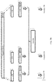
- FIG. 1 is a framework diagram of a communications system.
- the communications system includes a network device 01 and a terminal device 02.
- the communications system may be a long term evolution (Long Term Evolution, LTE) communications system, or a 5 th generation (5-Generation, 5G) mobile communications system, for example, a new generation (New Radio, NR) radio access technology. This is not limited herein.
- LTE Long Term Evolution
- 5G 5 th generation
- NR new Generation
- the network device included in this application may include but is not limited to a base station and a transmission reception point (Transmission Reception Point, TRP).
- the base station is also referred to as a radio access network (Radio Access Network, RAN) device, and is a device that connects a terminal to a wireless network.
- Radio Access Network Radio Access Network
- the base station may be a base transceiver station (Base Transceiver Station, BTS) in global system for mobile communications (Global System of Mobile communication, GSM) or code division multiple access (Code Division Multiple Access, CDMA); or may be a NodeB (NodeB, NB) in wideband code division multiple access (Wideband Code Division Multiple Access, WCDMA); or may be an evolved NodeB (Evolutional Node B, eNB or eNodeB) in long term evolution (Long Term Evolution, LTE), a relay station, an access point, a base station on a future 5G network, or the like. This is not limited herein.
- the terminal device may be a wireless terminal or a wired terminal.
- the wireless terminal may be a device that provides voice and/or other service data connectivity for a user, a handheld device with a wireless connection function, or another processing device connected to a wireless modem.
- the wireless terminal may communicate with one or more core networks through a radio access network (Radio Access Network, RAN).
- the wireless terminal may be a mobile terminal, for example, a mobile phone (also referred to as a "cellular" phone) or a computer with a mobile terminal.
- the wireless terminal may be a portable, pocket-sized, handheld, computer built-in, or in-vehicle mobile apparatus, which exchanges voice and/or data with the radio access network.
- the wireless terminal may be a device such as a personal communication service (Personal Communication Service, PCS) phone, a cordless phone, a session initiation protocol (Session Initiation Protocol, SIP) phone, a wireless local loop (Wireless Local Loop, WLL) station, or a personal digital assistant (Personal Digital Assistant, PDA).
- PCS Personal Communication Service
- SIP Session Initiation Protocol
- WLL Wireless Local Loop
- PDA Personal Digital Assistant
- the wireless terminal may also be referred to as a system, a subscriber unit (Subscriber Unit), a subscriber station (Subscriber Station), a mobile station (Mobile Station), a mobile (Mobile), a remote station (Remote Station), a remote terminal (Remote Terminal), an access terminal (Access Terminal), a user terminal (User Terminal), a user agent (User Agent), a user device (User Device or User Equipment). This is not limited herein.
- a DMRS port is an antenna port used to send a DMRS.
- the antenna port is also used to send a physical data channel or a physical control channel.
- the DMRS sent through the antenna port may be used to perform channel estimation and signal demodulation on the physical data channel or the physical control channel sent through the antenna port.
- a DMRS port, a DMRS antenna port, and the like are not differentiated in the embodiments of this application, and are corresponding to a same meaning.
- DMRS ports in a DMRS port group meet a quasi-co-location (Quasi-Co-Location, QCL) requirement, and two DMRS ports belonging to different DMRS port groups do not meet the QCL requirement.
- QCL quasi-co-location
- a large scale feature corresponding to a channel that a signal sent through an antenna port goes through can be obtained based on a large scale feature corresponding to a channel that a signal sent through another antenna port goes through, it is considered that these two antenna ports meet the QCL requirement.
- the large scale feature includes but is not limited to delay spread, an average delay, average power, Doppler spread, a Doppler shift, and spatial information (for example, an angle of arrival and a receive antenna correlation).
- the network device may be configured to perform coherent MIMO communication (that is, DMRS ports corresponding to different antenna panels in the network device belong to a same DMRS port group, or DMRS ports corresponding to the network device and another network device belong to a same DMRS port group), or may be configured to perform non-coherent MIMO communication (that is, DMRS ports corresponding to different antenna panels in the network device belong to different DMRS port groups, or DMRS ports corresponding to the network device and another network device belong to different DMRS port groups).
- coherent MIMO communication that is, DMRS ports corresponding to different antenna panels in the network device belong to a same DMRS port group, or DMRS ports corresponding to the network device and another network device belong to a same DMRS port group
- non-coherent MIMO communication that is, DMRS ports corresponding to different antenna panels in the network device belong to different DMRS port groups, or DMRS ports corresponding to the network device and another network device belong to different DMRS port groups.
- a process of mapping a CBG or a transport block to a corresponding transport layer further includes but is not limited to the following process: sequentially performing processes such as scrambling, modulation, and layer mapping on the CBG or the transport block.
- a physical uplink shared channel scrambling process in the section 5.3.1 physical uplink shared channel modulation and layer mapping processes in the section 5.3.2, a physical downlink shared channel scrambling process in the section 6.3.1, a physical downlink shared channel modulation process in the section 6.3.2, and a layer mapping process during spatial multiplexing transmission of a physical downlink shared channel in the section 6.3.3.2. Details are not described herein. It can be understood that the process of mapping a CBG or data to a corresponding transport layer may be alternatively performed in another existing manner or a future manner. This is not limited in the embodiments of this application.
- a mapping relationship between a DMRS port group and a corresponding transport layer is predefined in the network device and/or the terminal device, or the network device dynamically configures, by using a higher layer message or a physical layer message, a mapping relationship, between a DMRS port group and a corresponding transport layer, in the network device and/or the terminal device, so that a transport layer to which data corresponding to a DMRS port group is mapped can be learned of when the DMRS port group is learned of.
- one antenna port is used to send a data flow corresponding to one transport layer. Therefore, it can be considered that a transport layer and an antenna port are in a one-to-one mapping relationship.
- a transport layer and an antenna port may not be differentiated, and may be considered as equivalent based on a mapping relationship.
- the following describes in detail a data communication method, a network device, and a terminal device provided in the embodiments of this application.
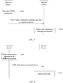
- FIG. 2A is a schematic flowchart of Embodiment 1 of a data communication method according to this application.
- This embodiment of this application describes non-coherent MIMO communication (that is, there are a plurality of DMRS antenna port groups).
- the method in this embodiment may include the following steps.
- Step S201 A network device determines DMRS port groups.
- the network device determines the DMRS port groups used by the network device to communicate data with a terminal device.
- a quantity of the DMRS port groups is greater than or equal to 2.
- the network device performs user scheduling and resource allocation with reference to network load and an interference status and based on channel state information fed back by the terminal device, an uplink sounding reference signal sent by the terminal device, or the like, to determine the DMRS port groups used by the network device to communicate data with the terminal device.
- the network device may alternatively determine the DMRS port groups in another manner. This is not limited in this embodiment of this application.
- Step S202 A terminal device obtains configuration information of the demodulation reference signal DMRS port groups.
- manners of obtaining, by the terminal device, the configuration information of the DMRS port groups may include but are not limited to the following manners: receiving, by the terminal device, a notification message (optionally, the notification message carries the configuration information of the DMRS port groups, and information about antenna ports included in the DMRS port groups) sent by the network device; or obtaining, by the terminal device, predefined configuration information of the DMRS port groups.
- the notification message may include but is not limited to any one of or a combination of the following: downlink control information (Downlink Control Information, DCI), a radio resource control (Radio Resource Control, RRC) message, and a media access control control element (Media Access Control Control Element, MAC CE).
- Step S203 The network device and the terminal device perform data communication.
- the data is corresponding to a transport block.
- the transport block is divided into at least one code block group CBG.
- Each of the at least one CBG is corresponding to one DMRS port group (that is, different DMRS port groups are corresponding to different CBGs, and one CBG is not corresponding to a plurality of DMRS port groups) and is mapped to a transport layer corresponding to the one DMRS port group.
- the network device sends data to the terminal device, where the data is corresponding to a transport block, (Transport Block, TB).
- the network device divides the transport block into at least one code block group CBG.
- Each of the at least one CBG is corresponding to one DMRS port group (that is, different DMRS port groups are corresponding to different CBGs, and one CBG is not corresponding to a plurality of DMRS port groups), and each of the at least one CBG is mapped to a transport layer corresponding to the one DMRS port group.
- the network device determines that the DMRS port groups include a DMRS port group 1 and a DMRS port group 2 (that is, the quantity of the DMRS port groups is equal to 2).
- the transport block is divided into two CBGs (including a CBG 1 corresponding to the DMRS port group 1 and a CBG 2 corresponding to the DMRS port group 2), and the CBG 1 is mapped to a transport layer corresponding to the DMRS port group 1, and the CBG 2 is mapped to a transport layer corresponding to the DMRS port group 2.
- the transport block may be alternatively divided into CBGs whose quantity is an integer multiple of the quantity of the DMRS port groups (for example, the transport block is divided into a CBG 1 to a CBG 4).
- each DMRS port group is corresponding two CBGs (for example, the DMRS port group 1 is corresponding to the CBG 1 and the CBG 2, and the DMRS port group 2 is corresponding to the CBG 3 and the CBG 4). It can be learned that, it is ensured that data flows sent through different DMRS port groups belong to different CBGs, so that the terminal device can independently decode a CBG corresponding to each DMRS port group.
- the terminal device receives the data sent by the network device, and decodes the received data based on the learned DMRS port groups (for example, learns of the DMRS port groups based on the configuration information of the DMRS port groups in step S202).
- the terminal device can learn of a division manner of the transport block (for example, a quantity of CBGs into which the transport block is divided) and a resource mapping manner of the transport block (for example, a transport layer to which the transport block is mapped) based on the DMRS port groups, so that the terminal device can independently decode a CBG corresponding to each DMRS port group.
- the terminal device For uplink data transmission, after the terminal device learns of the configuration information of the DMRS port groups (in other words, learns of the DMRS port groups), the terminal device sends data to the network device, where the data is corresponding to a transport block (for example, a TB).
- the terminal device divides the transport block into at least one code block group CBG.
- Each of the at least one CBG is corresponding to one DMRS port group (that is, different DMRS port groups are corresponding to different CBGs, and one CBG is not corresponding to a plurality of DMRS port groups), and each of the at least one CBG is mapped to a transport layer corresponding to the one DMRS port group. It can be learned that, it is ensured that data flows sent through different DMRS port groups belong to different CBGs, so that the network device can independently decode a CBG corresponding to each DMRS port group.
- the network device receives the data sent by the terminal device, and decodes the received data based on the determined DMRS antenna port groups.
- the network device can learn of a division manner of the transport block (for example, a quantity of CBGs into which the transport block is divided) and a resource mapping manner of the transport block (for example, a transport layer to which the transport block is mapped) based on the DMRS port groups, so that the network device can independently decode a CBG corresponding to each DMRS port group.
- implementations of dividing the transport block into the at least one CBG may include but are not limited to the following two implementations.
- the N CBs are grouped into CBGs corresponding to the DMRS port groups (that is, each DMRS port group is corresponding to at least one CBG, different DMRS port groups are corresponding to different CBGs, and one CBG is not corresponding to a plurality of DMRS port groups).
- a specific manner of concatenating the N CBs in the process of grouping the N CBs into the CBGs corresponding to the DMRS port groups is not limited in this embodiment of this application.
- a quantity of CBs included in each CBG is equal to a value calculated based on the following formula: ⁇ ( B 0 / E s ) ⁇ N ⁇ or ⁇ ( B 0 / B s ) ⁇ N ⁇ .
- a total quantity of CBs included in all CBGs is equal to a total quantity N of CBs in a system.
- B 0 represents a quantity of bits of data sent through a DMRS port group corresponding to the CBG
- B s represents a total quantity of bits of data sent through the DMRS port groups
- ⁇ ⁇ represents a round-down operation
- ⁇ ⁇ represents a round-up operation.
- a quantity of bits of data sent through each DMRS port is equal to a modulation and coding scheme (Modulation and Coding Scheme, MCS) at a transport layer corresponding to the DMRS port ⁇ a quantity of transport layers corresponding to the DMRS port ⁇ a quantity of physical time-frequency resource elements (Resource Element, RE) that are used for data communication and that are allocated to the transport layer corresponding to the DMRS port.
- MCS Modulation and Coding Scheme
- a quantity of bits of data sent through the DMRS port group 1 is B1
- a quantity of bits of data sent through the DMRS port group 2 is B2
- the transport block is divided into N code blocks CBs
- a quantity of CBs included in the CBG 1 corresponding to the DMRS port group 1 is equal to ⁇ B 1 B 1 + B 2 ⁇ N ⁇
- a quantity of CBs included in the CBG 2 corresponding to the DMRS port group 2 is equal to a value of N ⁇ ⁇ B 1 B 1 + B 2 ⁇ N ⁇ .
- a quantity of CBs included in the CBG 1 corresponding to the DMRS port group 1 is equal to ⁇ B 1 B 1 + B 2 ⁇ N ⁇
- a quantity of CBs included in the CBG 2 corresponding to the DMRS port group 2 is equal to a value of N ⁇ ⁇ B 1 B 1 + B 2 ⁇ N ⁇ .
- FIG. 2B is a schematic diagram of CB division according to an embodiment of this application. As shown in FIG.
- a transport block (for example, a TB) may be considered as media access control (Media Access Control, MAC) layer data, and the transport block with added cyclic redundancy check (Cyclic Redundancy Check, CRC) is usually divided into N CBs. Then independent CRC is applied to each CB, and each CB is encoded to obtain N encoded CBs.
- Media Access Control Media Access Control
- CRC Cyclic Redundancy Check
- the transport block is divided into a transport sub-block corresponding to each DMRS port group (that is, each DMRS port group is corresponding to one transport sub-block, different DMRS port groups are corresponding to different transport sub-blocks, and one transport sub-block is not corresponding to a plurality of DMRS port groups); and each transport sub-block is encoded to obtain a CBG corresponding to the DMRS port group.
- each transport sub-block refer to a general coding process in the section 5.1 in the version 13.1.0 (v13.1.0) of 3GPP LTE TS 36.212. Details are not described herein. It can be understood that the process of coding the transport sub-block may be alternatively performed in another existing manner or a future manner, and a parameter used in the coding process may be different from that in the existing solution. This is not limited in this embodiment of the present invention.
- sequence numbers of the foregoing steps constitute no limitation on execution sequences, and the execution sequences of the steps should be determined based on functions and internal logic of the steps. This is not limited in this embodiment of this application.
- the network device and the terminal device perform data communication, where the data is corresponding to the transport block, the transport block is divided into the at least one code block group CBG, and each of the at least one CBG is corresponding to one DMRS port group and is mapped to a transport layer corresponding to the one DMRS port group. It can be learned that, it is ensured that data flows sent through different DMRS port groups belong to different CBGs, so that a receive end can independently decode a CBG corresponding to each DMRS port group (in other words, can independently decode data flows mapped to different transport layers), and therefore can support interference cancellation performed by an interference cancellation receiver.
- the receive end can independently decode the CBG corresponding to each DMRS port group, the receive end can perform ACK/NACK feedback in a form of a CBG. For example, when correctly decoding a CBG, the receive end feeds back an ACK; otherwise, the receive end feeds back a NACK.
- a transmit end needs to retransmit the CBG incorrectly decoded by the receive end, until the receive end correctly receives the CBG or a maximum quantity of retransmission times is reached.
- a mapped-to transport layer during retransmission may be the same as a mapped-to transport layer during initial transmission; or certainly, an exchange identifier may be used to indicate that a mapped-to transport layer during retransmission is different from a mapped-to transport layer during initial transmission. For example, assuming that the CBG 1 and the CBG 2 are incorrectly decoded, and that during initial transmission, the CBG 1 is mapped to first two layers and the CBG 2 is mapped to last two layers, based on an exchange identifier, during retransmission, the CBG 1 is mapped to the last two layers and the CBG 2 is mapped to the first two layers.
- a transport layer to which the CBG 1 is mapped during retransmission is the same as a transport layer to which the CBG is mapped during initial transmission; or an exchange identifier may be used to indicate that a transport layer to which the CBG 1 is mapped during retransmission is the same as a transport layer to which the CBG 2 is mapped during initial transmission.
- Transport block division is performed at different transport layers or different antenna ports during MIMO communication based on a quantity of DMRS port groups, so that each DMRS port group is corresponding to at least one CBG.
- the at least one CBG corresponding to each DMRS port group may be corresponding to different symbol groups in time domain, and/or may be corresponding to different subband groups in frequency domain.
- a DMRS port group is corresponding to a CBG 1 to a CBG 3
- the CBG 1 and the CBG 2 are corresponding to a symbol group 1
- the CBG 3 is corresponding to a symbol group 2
- the CBG 1 is corresponding to a subband group 1
- the CBG 2 and the CBG 3 are corresponding to a subband group 2.
- a CBG may be further mapped in time domain and/or frequency domain.
- layer mapping (the resource mapping manner described in Embodiment 1 of this application), frequency-domain mapping, and time-domain mapping are sequentially performed.
- frequency-domain mapping and/or time-domain mapping refer to existing mapping manners.
- time-domain mapping is performed based on a symbol group (including at least one symbol)
- frequency-domain mapping is performed based on a subband group (including at least one subband).
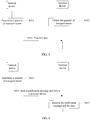
- FIG. 3 is a schematic flowchart of Embodiment 2 of a data communication method according to this application. Based on the foregoing embodiment, this embodiment of this application describes downlink non-coherent MIMO communication (that is, there are a plurality of DMRS antenna port groups). As shown in FIG. 3 , the method in this embodiment may include the following steps.
- Step S301 A network device determines demodulation reference signal DMRS port groups.
- the network device determines the DMRS port groups used by the network device to send data to a terminal device.
- a quantity of the DMRS port groups is greater than or equal to 2.
- Step S302 The network device sends a notification message and data to a terminal device.
- the notification message carries configuration information of the DMRS port groups, so that the terminal device can learn of the DMRS port groups based on the notification message.
- the data is corresponding to a transport block.
- the network device divides the transport block into at least one code block group CBG.
- Each of the at least one CBG is corresponding to one DMRS port group, and each of the at least one CBG is mapped to a transport layer corresponding to the one DMRS port group.
- For a specific division manner refer to Embodiment 1 of this application.
- For a resource mapping manner refer to Embodiment 1 or Embodiment 7 of this application. Details are not described herein again.
- Step S303 The terminal device receives the notification message and the data.
- the terminal device determines the DMRS port groups based on the notification message, and can learn of the division manner of the transport block (for example, a quantity of CBGs into which the transport block is divided) and the resource mapping manner of the transport block (for example, a transport layer to which the transport block is mapped) based on the DMRS port groups, so that the terminal device can independently decode a CBG corresponding to each DMRS port group (in other words, can independently decode data flows mapped to different transport layers), and can support interference cancellation performed by an interference cancellation receiver.
- the division manner of the transport block for example, a quantity of CBGs into which the transport block is divided
- the resource mapping manner of the transport block for example, a transport layer to which the transport block is mapped
- FIG. 4 is a schematic flowchart of Embodiment 3 of a data communication method according to this application. Based on the foregoing embodiment, this embodiment of this application describes uplink non-coherent MIMO communication (that is, there are a plurality of DMRS antenna port groups). As shown in FIG. 4 , the method in this embodiment may include the following steps.
- Step S401 A terminal device obtains configuration information of demodulation reference signal DMRS port groups.
- the terminal device learns, based on the configuration information of the DMRS port groups, of the DMRS port groups used by the terminal device to send data to a network device.
- a quantity of the DMRS port groups is greater than or equal to 2.
- the configuration information of the DMRS port groups may be notified by the network device to the terminal device, or may be predefined in the terminal device (correspondingly, configuration information of the DMRS port groups is also predefined in the network device).
- Step S402 The terminal device sends data to a network device.
- the data is corresponding to a transport block.
- the terminal device divides the transport block into at least one code block group CBG.
- Each of the at least one CBG is corresponding to one DMRS port group, and each of the at least one CBG is mapped to a transport layer corresponding to the one DMRS port group.
- For a specific division manner refer to Embodiment 1 of this application.
- For a resource mapping manner refer to Embodiment 1 or Embodiment 7 of this application. Details are not described herein again.
- Step S403 The network device receives the data.
- the network device can learn of the division manner of the transport block (for example, a quantity of CBGs into which the transport block is divided) and the resource mapping manner of the transport block (for example, a transport layer to which the transport block is mapped) based on the DMRS port groups used by the terminal device to send the data to the network device, so that the network device can independently decode a CBG corresponding to each DMRS port group.
- the division manner of the transport block for example, a quantity of CBGs into which the transport block is divided
- the resource mapping manner of the transport block for example, a transport layer to which the transport block is mapped
- FIG. 5 is a schematic flowchart of Embodiment 4 of a data communication method according to this application.
- This embodiment of this application describes coherent MIMO communication (that is, there is one DMRS antenna port group).
- the method in this embodiment may include the following steps.
- Step S501 A network device determines a quantity of transport layers.
- the network device determines a quantity of transport layers corresponding to each transport block (for example, TB).
- the network device determines, based on scheduling result information (for example, a downlink reference signal for measurement or an uplink sounding reference signal) sent by a terminal device, a total quantity of transport layers used for data communication between the network device and the terminal device.
- scheduling result information for example, a downlink reference signal for measurement or an uplink sounding reference signal
- scheduling result information for example, a downlink reference signal for measurement or an uplink sounding reference signal
- transmission for one transport block is supported; or when the total quantity of transport layers is greater than 4 and less than or equal to 8, transmission for two transport blocks is supported. It can be learned that when the total quantity of transport layers is determined, the network device can learn of the quantity of transport layers corresponding to each transport block.
- the network device may alternatively determine the quantity of transport layers in another manner. This is not limited in this embodiment of this application.
- Step S502 A terminal device obtains the quantity of transport layers.
- manners of obtaining the quantity of transport layers by the terminal device may include but are not limited to the following manners: receiving, by the terminal device, a notification message (optionally, the notification message carries configuration information of the quantity of transport layers) sent by the network device; or obtaining, by the terminal device, predefined configuration information of the quantity of transport layers.
- the notification message may include but is not limited to any one of the following: downlink control information (Downlink Control Information, DCI), a radio resource control (Radio Resource Control, RRC) message, and a MAC CE.
- the notification message may further carry information about an antenna port included in the DMRS port group, so that the terminal device can learn of an antenna port used for data communication.
- the terminal device may alternatively obtain predefined information about an antenna port included in the DMRS port group. Certainly, the terminal device may alternatively obtain the information about the antenna port in another manner. This is not limited in this embodiment of this application.
- Step S503 The network device and the terminal device perform data communication.
- implementations of mapping the transport block to the corresponding transport layer based on the quantity of transport layers include but are not limited to the following two implementations.
- the transport block is mapped to the corresponding transport layer. For example, when the quantity of transport layers is equal to 1, the transport block is mapped to corresponding one transport layer; when the quantity of transport layers is equal to 2, the transport block is mapped to corresponding two transport layers; when the quantity of transport layers is equal to 3, the transport block is sequentially mapped to corresponding three transport layers; or when the quantity of transport layers is equal to 4, the transport block is sequentially mapped to corresponding four transport layers.
- a second implementation (A) if the quantity of transport layers is equal to 1 or 2, the transport block is mapped to the corresponding transport layer. (B) If the quantity of transport layers is equal to 3 or 4, and a group configuration message is used to instruct to divide the transport block, the transport block is divided into two code block groups CBGs, and the two CBGs are mapped to different transport layers; or if the group configuration message is not obtained, the transport block is mapped to corresponding transport layers. For example, if the terminal device obtains the group configuration message, the transport block is divided into two CBGs; or if the terminal device does not obtain the group configuration message, the transport block is directly mapped to corresponding transport layers.
- the terminal device may obtain the group configuration message by receiving the group configuration message sent by the network device, or may obtain the group configuration message by obtaining a preconfigured group configuration message, or certainly, may obtain the group configuration message in another manner. This is not limited in this embodiment of this application.
- the network device receives the data sent by the terminal device.
- the network device directly decodes the received data based on the quantity of transport layers (for example, based on the quantity of transport layers that is determined in step S501).
- the network device can learn of a resource mapping manner of the data (for example, a transport layer to which the data is mapped) based on the quantity of transport layers.
- the network device can learn, based on the quantity of transport layers, of a resource mapping manner used when the quantity of transport layers is equal to 1 or 2, and can determine, based on the group configuration message, resource division (for example, a quantity of CBGs into which the data is divided) and mapping (for example, a transport layer to which the data is mapped) manners used when the quantity of transport layers is equal to 3 or 4.
- resource division for example, a quantity of CBGs into which the data is divided
- mapping for example, a transport layer to which the data is mapped
- sequence numbers of the foregoing steps constitute no limitation on execution sequences, and the execution sequences of the steps should be determined based on functions and internal logic of the steps. This is not limited in this embodiment of this application.
- the network device and the terminal device perform data communication, where the data is corresponding to the transport block, and the transport block is mapped to the corresponding transport layer based on the quantity of transport layers. It can be learned that flexible resource mapping can be implemented based on different quantities of transport layers, to adapt to different service requirements, different transmission scenarios, different channel statuses, or the like.
- a mapping manner during initial transmission describes a mapping manner during retransmission.
- a quantity of transport layers corresponding to a single transport block is equal to 1 or 2
- a mapped-to transport layer during retransmission is the same as a mapped-to transport layer during initial transmission.
- a quantity of transport layers corresponding to a single transport block is equal to 3 or 4
- a mapped-to transport layer during retransmission may be the same as a mapped-to transport layer during initial transmission; or certainly, an exchange identifier may be used to indicate that a mapped-to transport layer during retransmission is different from a mapped-to transport layer during initial transmission.
- the CBG 1 and the CBG 2 are incorrectly decoded, and that during initial transmission, the CBG 1 is mapped to first two layers and the CBG 2 is mapped to last two layers, based on an exchange identifier, during retransmission, the CBG 1 is mapped to the last two layers and the CBG 2 is mapped to the first two layers.
- a transport layer to which the CBG 1 is mapped during retransmission is the same as a transport layer to which the CBG is mapped during initial transmission; or an exchange identifier may be used to indicate that a transport layer to which the CBG 1 is mapped during retransmission is the same as a transport layer to which the CBG 2 is mapped during initial transmission.
- the CBG is obtained through transport block division merely at different transport layers during MIMO communication, namely, division in space domain. If division in time domain and/or frequency domain are/is further used, this embodiment of this application is also applicable to a CBG obtained through transport block division in space domain in combination with symbol division in time domain and/or subband division in frequency domain, and certainly, is also applicable to other cases. This is not limited in this embodiment of this application. Specifically, how to divide a transport block in time domain and/or frequency domain and how to perform resource mapping in time domain and/or frequency domain are not limited in this embodiment of this application.
- the foregoing embodiment of this application mainly describes mapping of a transport block in space domain.
- the transport block may be further mapped in time domain and/or frequency domain.
- layer mapping the resource mapping manner described in Embodiment 4 of this application
- frequency-domain mapping and time-domain mapping are sequentially performed.
- frequency-domain mapping and/or time-domain mapping refer to existing mapping manners.
- time-domain mapping is performed based on a symbol group (including at least one symbol)
- frequency-domain mapping is performed based on a subband group (including at least one subband).
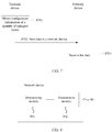
- FIG. 6 is a schematic flowchart of Embodiment 5 of a data communication method according to this application. Based on Embodiment 4, this embodiment of this application describes downlink coherent MIMO communication (that is, there is one DMRS antenna port group). As shown in FIG. 6 , the method in this embodiment may include the following steps.
- Step S601 A network device determines a quantity of transport layers.
- the network device determines a quantity of transport layers corresponding to each transport block (for example, TB).
- Step S602 The network device sends a notification message and data to a terminal device.
- the notification message carries configuration information of the quantity of transport layers, so that the terminal device can learn of the quantity of transport layers based on the notification message.
- the notification message may further carry information about an antenna port included in the DMRS port group, so that the terminal device can learn of an antenna port used for data communication.
- the data is corresponding to a transport block, and the transport block is mapped to a corresponding transport layer based on the quantity of transport layers.
- the transport block is mapped to a corresponding transport layer based on the quantity of transport layers.
- Step S603 The terminal device receives the notification message and the data.
- the terminal device determines, based on the notification message, the quantity of transport layers and the antenna port included in the DMRS port group.
- the terminal device can directly learn of the resource mapping manner of the transport block (for example, a transport layer to which the transport block is mapped) based on the quantity of transport layers.
- the terminal device can learn, based on the quantity of transport layers, of a resource mapping manner used when the quantity of transport layers is equal to 1 or 2, and can learn, based on the group configuration message, of resource division and mapping manners used when the quantity of transport layers is equal to 3 or 4. It can be learned that flexible resource mapping can be implemented based on different quantities of transport layers, to adapt to different service requirements, different transmission scenarios, different channel statuses, or the like.
- FIG. 7 is a schematic flowchart of Embodiment 6 of a data communication method according to this application. Based on Embodiment 4, this embodiment of this application describes uplink coherent MIMO communication (that is, there is one DMRS antenna port group). As shown in FIG. 7 , the method in this embodiment may include the following steps.
- Step S701 A terminal device obtains configuration information of a quantity of transport layers.
- the terminal device learns, based on the configuration information of the quantity of transport layers, of a quantity of transport layers corresponding to each transport block (for example, a TB).
- the configuration information of the quantity of transport layers may be notified by a network device to the terminal device, or may be predefined in the terminal device (correspondingly, configuration information of the quantity of transport layers is also predefined in the network device).
- the terminal device may further obtain information about an antenna port included in the DMRS port group, and therefore can learn of an antenna port used to send data to the network device. For a manner of obtaining the information about the antenna port, refer to related descriptions in Embodiment 5 of this application. Details are not described herein again.
- Step S702 The terminal device sends data to the network device.
- the data is corresponding to a transport block, and the transport block is mapped to a corresponding transport layer based on the quantity of transport layers.
- the transport block is mapped to a corresponding transport layer based on the quantity of transport layers.
- Step S703 The network device receives the data.
- the network device receives the data sent by the terminal device.
- the network device can directly learn of the resource mapping manner of the data (for example, a transport layer to which the data is mapped) based on the quantity of transport layers.
- the network device can learn, based on the quantity of transport layers, of a resource mapping manner used when the quantity of transport layers is equal to 1 or 2, and can learn, based on the group configuration message, resource division (for example, a quantity of CBGs into which the data is divided) and mapping (a transport layer to which the data is mapped) manners used when the quantity of transport layers is equal to 3 or 4. It can be learned that flexible resource mapping can be implemented based on different quantities of transport layers, to adapt to different service requirements, different transmission scenarios, different channel statuses, or the like.
- Embodiment 7 of the data communication method in this application implementations of that "each of the at least one CBG is mapped to a transport layer corresponding to the one DMRS port group" in Embodiment 1 to Embodiment 3 are described.
- each of the at least one CBG is mapped to a transport layer corresponding to the one DMRS port group includes:
- a preset quantity of data bits are sequentially extracted in a first preset order from a data bit sequence included in a CBG corresponding to each DMRS port group, and serial concatenation is performed on the data bits to obtain a concatenated data bit sequence may be implemented in at least one of the following several implementations.
- a preset quantity of data bits are sequentially extracted in a preset order from a data bit sequence included in a CBG corresponding to each DMRS port group.
- quantities of data bits extracted from data bit sequences included in CBGs corresponding to different DMRS port groups may be the same or different, in other words, preset quantities corresponding to different DMRS port groups may be the same or different.
- the preset order in the first implementation is the first preset order.
- serial concatenation is sequentially performed on the extracted data bits to obtain the concatenated data bit sequence.
- the preset order may be an ascending order of sequence numbers of DMRS port groups, or a descending order of sequence numbers of DMRS port groups, or another preset order, or a network-configured order.
- the network-configured order may be explicitly indicated by using higher layer signaling or physical layer signaling.
- a second preset order in the following embodiments, for example, an ascending order of sequence numbers of DMRS port groups, or a descending order of sequence numbers of DMRS port groups, or another preset order, or a network-configured order
- a preset order for example, an ascending order of sequence numbers of DMRS port groups, or a descending order of sequence numbers of DMRS port groups, or another preset order, or a network-configured order
- quantities of bits extracted from data bit sequences included in CBGs corresponding to different DMRS port groups may be the same or different, in other words, preset quantities corresponding to different DMRS port groups may be the same or different.
- Qi the number of bits extracted from data bit sequences included in CBGs corresponding to different DMRS port groups
- a preset quantity of data bits are sequentially extracted in a first preset order from a data bit sequence included in a CBG corresponding to each DMRS port group, and serial concatenation is performed on the data bits to obtain a concatenated data bit sequence may be alternatively implemented in another implementation. This is not limited in this embodiment of this application.
- this embodiment of this application describes in detail the second implementation of that "a preset quantity of data bits are sequentially extracted in a first preset order from a data bit sequence included in a CBG corresponding to each DMRS port group, and serial concatenation is performed on the data bits to obtain a concatenated data bit sequence".
- an s th data bit in the concatenated data bit sequence obtained by sequentially extracting the preset quantity of data bits in the first preset order from the data bit sequence included in the CBG corresponding to each DMRS port group and performing serial concatenation on the data bits is corresponding to an ( f s ⁇ Qs+ a s ) th data bit of a q s th CBG, to ensure that the data bits included in the CBG corresponding to each DMRS port group can be mapped to a transport layer corresponding to the DMRS port in a sequential order, and further enable an interference cancellation receiver to cancel interference between different transport layers.
- Qs represents a quantity of data bits extracted from a data bit sequence included in a CBG corresponding to an s th DMRS port group.
- Qt represents a quantity of data bits extracted from a data bit sequence included in a CBG corresponding to a t th DMRS port group
- Q0 0.
- the concatenated data bit sequence is mapped to each transport layer according to a predefined mapping policy (for example, interleaved mapping), to ensure that the CBG corresponding to each DMRS port group is mapped to a transport layer corresponding to the DMRS port group.
- a predefined mapping policy for example, interleaved mapping
- all data bits included in a CBG corresponding to a DMRS port group 1 are mapped to a transport layer (optionally, there may be one or more layers) corresponding to the DMRS port group 1, and all data bits included in a CBG corresponding to a DMRS port group 2 are mapped to a transport layer corresponding to the DMRS port group 2.
- the concatenated data bit sequence is mapped to each transport layer according to a predefined mapping policy (for example, sequential mapping), to ensure that the CBG corresponding to each DMRS port group is mapped to a transport layer corresponding to the DMRS port group.
- a predefined mapping policy for example, sequential mapping
- the concatenated data bit sequence is mapped to each transport layer according to a corresponding predefined mapping policy, to ensure that the CBG corresponding to each DMRS port group is mapped to a transport layer corresponding to the DMRS port group. This is not limited in this embodiment of this application.
- the concatenated data bit sequence is mapped to each transport layer according to a predefined mapping policy may include the following processing process. For example, at least one of processes such as time-domain interleaving, frequency-domain interleaving, time-frequency interleaving, scrambling, modulation, and layer mapping is performed on the concatenated data bit sequence. Certainly, another processing process may be further included. This is not limited in this embodiment of this application.
- each of the at least one CBG is mapped to a transport layer corresponding to the one DMRS port group may be alternatively implemented in another implementation. This is not limited in this embodiment of this application.
- a mapping relationship between a DMRS port group and a corresponding transport layer is predefined in the network device and/or the terminal device, or the network device and/or the terminal device dynamically learns of a mapping relationship between a DMRS port group and a corresponding transport layer by using a higher layer message or a physical layer message,
- L i (that is, a quantity of transport layers corresponding to each DMRS port group) in the foregoing embodiment may be determined based on a mapping relationship between each DMRS port group and a corresponding transport layer.
- L i in the foregoing embodiment may be alternatively indicated by using DCI.
- the quantity of transport layers corresponding to each DMRS port group may be alternatively indicated in another manner. This is not limited in this embodiment of this application.
- the quantity of transport layers corresponding to each DMRS port group is indicated by using DCI
- a CBG that is corresponding to a DMRS port group (referred to as a j th DMRS port group in the following embodiment, where 1 ⁇ j ⁇ R) and that needs to be filled with a placeholder satisfies the following feature:
- a quantity C0 of times required for extracting an entire data bit sequence included in the CBG corresponding to the j th DMRS port group is less than a quantity Cmax of times required for extracting an entire data bit sequence included in a CBG corresponding to a p th DMRS port group.
- the quantity Cmax of times required for extracting the entire data bit sequence included in the CBG corresponding to the p th DMRS port group is a maximum quantity of times in quantities of times required for extracting all entire data bit sequences included in the CBGs corresponding to all the DMRS port groups, where 1 ⁇ p ⁇ R.
- a quantity of placeholders that need to be filled in the CBG corresponding to the j th DMRS port group is Qj ⁇ (Cmax-C0).
- the network device and the terminal device perform data communication, where the data is corresponding to the transport block, the transport block is divided into the at least one code block group CBG, and each of the at least one CBG is corresponding to one DMRS port group.
- the preset quantity of data bits are sequentially extracted in the first preset order from the data bit sequence included in the CBG corresponding to each DMRS port group, and serial concatenation is performed on the data bits to obtain the concatenated data bit sequence.
- the concatenated data bit sequence is mapped to each transport layer according to the predefined mapping policy, to ensure that the CBG corresponding to each DMRS port group is mapped to a transport layer corresponding to the DMRS port group.
- the foregoing embodiment of this application mainly describes a process of mapping, to a corresponding transport layer, a CBG obtained through division in space domain (for example, a transport layer or an antenna port), and imposes no limitation or requirement on mapping of a CBG obtained through division in time domain or frequency domain. If division in time domain and/or frequency domain are/is further used, this embodiment of this application is also applicable to a CBG obtained through transport block division in space domain in combination with symbol division in time domain and/or subband division in frequency domain, and certainly, is also applicable to other cases. This is not limited in this embodiment of this application.
- mapping to a corresponding physical resource, a CBG obtained through division in space domain in combination with division in time domain and/or frequency domain, CBGs mapped to a same time-domain symbol and/or frequency-domain subband may be mapped according to the process, described in the foregoing embodiment of this application, of mapping a CBG to a corresponding transport layer (that is, space-domain mapping).
- the process of mapping a CBG to a corresponding transport layer in Embodiment 4 to Embodiment 6 of this application may be alternatively replaced with the mapping process in Embodiment 7 of this application (this is equivalent to replacing a DMRS port group with a transport layer group corresponding to each CBG, where the transport layer group is a set of transport layers to which the CBG is mapped).
- the mapping process refer to corresponding content in Embodiment 7 of this application. Details are not described herein again.
- Embodiment 7 of the data communication method in this application may be alternatively performed independently from any one of Embodiment 1 to Embodiment 6, without depending on the other embodiments.
- the implementations, described in Embodiment 7 of the data communication method in this application, about mapping a CBG to a corresponding transport layer may also be applied to other data communication processes. This is not limited in this embodiment of this application.
- FIG. 8 is a schematic structural diagram of Embodiment 1 of a network device according to this application.
- the network device 80 provided in this embodiment includes a determining module 801 and a communication module 802.
- the determining module 801 is configured to determine demodulation reference signal DMRS port groups, where a quantity of the DMRS port groups is greater than or equal to 2.
- the communication module 802 is configured to communicate data with a terminal device, where the data is corresponding to a transport block, the transport block is divided into at least one code block group CBG, and each of the at least one CBG is corresponding to one DMRS port group and is mapped to a transport layer corresponding to the one DMRS port group.
- the transport block is divided into at least one CBG includes:
- a quantity of CBs included in each CBG is equal to a value calculated based on the following formula: ⁇ ( B 0 / B s ) ⁇ N ⁇ or ⁇ ( B 0 / B s ) ⁇ N ⁇ , where B 0 represents a quantity of bits of data sent through a DMRS port group corresponding to the CBG, B s represents a total quantity of bits of data sent through the DMRS port groups, ⁇ ⁇ represents a round-down operation, and ⁇ ⁇ represents a round-up operation.
- the transport block is divided into at least one CBG includes:
- the network device further includes: a notification module, configured to send a notification message to the terminal device, where the notification message carries configuration information of the DMRS port groups.
- a notification module configured to send a notification message to the terminal device, where the notification message carries configuration information of the DMRS port groups.
- each of the at least one CBG is mapped to a transport layer corresponding to the one DMRS port group includes:
- a preset quantity of data bits are sequentially extracted in a first preset order from a data bit sequence included in a CBG corresponding to each DMRS port group, and serial concatenation is performed on the data bits to obtain a concatenated data bit sequence includes:
- the network device in this embodiment may be configured to perform the technical solution in any one of Embodiment 1 to Embodiment 3, or Embodiment 7 of the data communication method in this application. Implementation principles and technical effects thereof are similar. Details are not described herein again.
- FIG. 9 is a schematic structural diagram of Embodiment 2 of a network device according to this application.
- the network device 90 provided in this embodiment includes a memory 901, a processor 902, a transceiver 903, and at least one communications bus 904.
- the communications bus 904 is configured to implement a communications connection between elements.
- the memory 901 may include a high-speed RAM, or may include a nonvolatile memory NVM, for example, at least one magnetic disk memory.
- the memory 901 may store various programs used to perform various processing functions and implement the method steps in the foregoing embodiments of this application.
- the transceiver 903 may be a corresponding output/output interface with a communication function.
- the processor 902 is configured to invoke a program instruction in the memory 901 to perform the following step: determining demodulation reference signal DMRS port groups, where a quantity of the DMRS port groups is greater than or equal to 2.
- the transceiver 903 is configured to communicate data with a terminal device, where the data is corresponding to a transport block, the transport block is divided into at least one code block group CBG, and each of the at least one CBG is corresponding to one DMRS port group and is mapped to a transport layer corresponding to the one DMRS port group.
- the transport block is divided into at least one CBG includes:
- a quantity of CBs included in each CBG is equal to a value calculated based on the following formula: ⁇ ( B 0 / B s ) ⁇ N ⁇ or ⁇ ( B 0 / B s ) ⁇ N ⁇ , where B 0 represents a quantity of bits of data sent through a DMRS port group corresponding to the CBG, B s represents a total quantity of bits of data sent through the DMRS port groups, ⁇ ⁇ represents a round-down operation, and ⁇ ⁇ represents a round-up operation.
- the transport block is divided into at least one CBG includes:
- the transceiver 903 is further configured to send a notification message to the terminal device, where the notification message carries configuration information of the DMRS port groups.
- each of the at least one CBG is mapped to a transport layer corresponding to the one DMRS port group includes:
- a preset quantity of data bits are sequentially extracted in a first preset order from a data bit sequence included in a CBG corresponding to each DMRS port group, and serial concatenation is performed on the data bits to obtain a concatenated data bit sequence includes:
- the network device in this embodiment may be configured to perform the technical solution in any one of Embodiment 1 to Embodiment 3, or Embodiment 7 of the data communication method in this application. Implementation principles and technical effects thereof are similar. Details are not described herein again.
- FIG. 10 is a schematic structural diagram of Embodiment 1 of a terminal device according to this application.
- the terminal device 100 provided in this embodiment includes an obtaining module 1001 and a communication module 1002.
- the obtaining module 1001 is configured to obtain configuration information of demodulation reference signal DMRS port groups, where a quantity of the DMRS port groups is greater than or equal to 2.
- the communication module 1002 is configured to communicate data with a network device, where the data is corresponding to a transport block, the transport block is divided into at least one code block group CBG, and each of the at least one CBG is corresponding to one DMRS port group and is mapped to a transport layer corresponding to the one DMRS port group.
- the transport block is divided into at least one CBG includes:
- a quantity of CBs included in each CBG is equal to a value calculated based on the following formula: ⁇ ( B 0 / B s ) ⁇ N ⁇ or ⁇ ( B 0 / B s ) ⁇ N ⁇ , where B 0 represents a quantity of bits of data sent through a DMRS port group corresponding to the CBG, B s represents a total quantity of bits of data sent through the DMRS port groups, ⁇ ⁇ represents a round-down operation, and ⁇ ⁇ represents a round-up operation.
- the transport block is divided into at least one CBG includes:
- the obtaining module is specifically configured to receive a notification message sent by the network device, where the notification message carries the configuration information of the DMRS port groups.
- each of the at least one CBG is mapped to a transport layer corresponding to the one DMRS port group includes:
- a preset quantity of data bits are sequentially extracted in a first preset order from a data bit sequence included in a CBG corresponding to each DMRS port group, and serial concatenation is performed on the data bits to obtain a concatenated data bit sequence includes:
- the terminal device in this embodiment may be configured to perform the technical solution in any one of Embodiment 1 to Embodiment 3, or Embodiment 7 of the data communication method in this application. Implementation principles and technical effects thereof are similar. Details are not described herein again.
- FIG. 11 is a schematic structural diagram of Embodiment 2 of a terminal device according to this application.
- the terminal device 110 provided in this embodiment includes a memory 1101, a processor 1102, a transceiver 1103, and at least one communications bus 1104.
- the communications bus 1104 is configured to implement a communications connection between elements.
- the memory 1101 may include a high-speed RAM, or may include a nonvolatile memory NVM, for example, at least one magnetic disk memory.
- the memory 1101 may store various programs used to perform various processing functions and implement the method steps in the foregoing embodiments of this application.
- the transceiver 1103 may be a corresponding output/output interface with a communication function.
- the processor 1102 is configured to invoke a program instruction in the memory 1101 to perform the following step: obtaining configuration information of demodulation reference signal DMRS port groups, where a quantity of the DMRS port groups is greater than or equal to 2.
- the transceiver 1103 is configured to communicate data with a network device, where the data is corresponding to a transport block, the transport block is divided into at least one code block group CBG, and each of the at least one CBG is corresponding to one DMRS port group and is mapped to a transport layer corresponding to the one DMRS port group.
- the transport block is divided into at least one CBG includes:
- a quantity of CBs included in each CBG is equal to a value calculated based on the following formula: ⁇ ( B 0 / B s ) ⁇ N ⁇ or ⁇ ( B 0 / B s ) ⁇ N ⁇ , where B 0 represents a quantity of bits of data sent through a DMRS port group corresponding to the CBG, B s represents a total quantity of bits of data sent through the DMRS port groups, ⁇ ⁇ represents a round-down operation, and ⁇ ⁇ represents a round-up operation.
- the transport block is divided into at least one CBG includes:
- the transceiver is further configured to receive a notification message sent by the network device, where the notification message carries the configuration information of the DMRS port groups.
- the processor is further configured to obtain the configuration information of the DMRS port groups based on the notification message.
- each of the at least one CBG is mapped to a transport layer corresponding to the one DMRS port group includes:
- a preset quantity of data bits are sequentially extracted in a first preset order from a data bit sequence included in a CBG corresponding to each DMRS port group, and serial concatenation is performed on the data bits to obtain a concatenated data bit sequence includes:
- the terminal device in this embodiment may be configured to perform the technical solution in any one of Embodiment 1 to Embodiment 3, or Embodiment 7 of the data communication method in this application. Implementation principles and technical effects thereof are similar. Details are not described herein again.
- the network device includes a determining module and a communication module.
- a determining module for a schematic structural diagram of the network device, refer to FIG. 8 .
- the determining module is configured to determine a quantity of transport layers.
- the communication module is configured to communicate data with a terminal device, where the data is corresponding to a transport block, and the transport block is mapped to a corresponding transport layer based on the quantity of transport layers.
- the transport block is mapped to a corresponding transport layer based on the quantity of transport layers includes:
- the network device further includes: the determining module, configured to determine, based on that a difference between channel quantity information corresponding to different DMRS ports is greater than a preset threshold, to divide the transport block when the quantity of transport layers is equal to 3 or 4.
- the network device further includes: a sending module, configured to send a group configuration message to the terminal device, where the group configuration message is used to instruct to divide the transport block when the quantity of transport layers is equal to 3 or 4.
- a sending module configured to send a group configuration message to the terminal device, where the group configuration message is used to instruct to divide the transport block when the quantity of transport layers is equal to 3 or 4.
- the network device in this embodiment may be configured to perform the technical solution in any one of Embodiment 4 to Embodiment 6, or Embodiment 7 of the data communication method in this application. Implementation principles and technical effects thereof are similar. Details are not described herein again.
- the network device includes a memory, a processor, a transceiver, and at least one communications bus.
- a schematic structural diagram of the network device refer to FIG. 9 .
- the communications bus is configured to implement a communications connection between elements.
- the memory may include a high-speed RAM memory, or may include a nonvolatile memory NVM, for example, at least one magnetic disk memory.
- the memory may store various programs used to perform various processing functions and implement the method steps in the foregoing embodiments of this application.
- the transceiver may be a corresponding output/output interface with a communication function.
- the processor is configured to invoke a program instruction in the memory to perform the following step: determining a quantity of transport layers.
- the transceiver is configured to communicate data with a terminal device, where the data is corresponding to a transport block, and the transport block is mapped to a corresponding transport layer based on the quantity of transport layers.
- the transport block is mapped to a corresponding transport layer based on the quantity of transport layers includes:
- the processor is further configured to determine, based on that a difference between channel quantity information corresponding to different DMRS ports is greater than a preset threshold, to divide the transport block when the quantity of transport layers is equal to 3 or 4.
- the transceiver is further configured to send a group configuration message to the terminal device, where the group configuration message is used to instruct to divide the transport block when the quantity of transport layers is equal to 3 or 4.
- the network device in this embodiment may be configured to perform the technical solution in any one of Embodiment 4 to Embodiment 6, or Embodiment 7 of the data communication method in this application. Implementation principles and technical effects thereof are similar. Details are not described herein again.
- the terminal device includes an obtaining module and a communication module.
- the terminal device includes an obtaining module and a communication module.
- FIG. 10 for a schematic structural diagram of the terminal device, refer to FIG. 10 .
- the obtaining module is configured to obtain a quantity of transport layers.
- the communication module is configured to communicate data with a network device, where the data is corresponding to a transport block, and the transport block is mapped to a corresponding transport layer based on the quantity of transport layers.
- the transport block is mapped to a corresponding transport layer based on the quantity of transport layers includes:
- the terminal device further includes: a receiving module, configured to receive the group configuration message sent by the network device.
- the terminal device in this embodiment may be configured to perform the technical solution in any one of Embodiment 4 to Embodiment 6, or Embodiment 7 of the data communication method in this application. Implementation principles and technical effects thereof are similar. Details are not described herein again.
- the terminal device includes a memory, a processor, a transceiver, and at least one communications bus.
- a schematic structural diagram of the terminal device refer to FIG. 11 .
- the communications bus is configured to implement a communications connection between elements.
- the memory may include a high-speed RAM, or may include a nonvolatile memory NVM, for example, at least one magnetic disk memory.
- the memory may store various programs used to perform various processing functions and implement the method steps in the foregoing embodiments of this application.
- the transceiver may be a corresponding output/output interface with a communication function.
- the processor is configured to invoke a program instruction in the memory to perform the following step: obtaining a quantity of transport layers.
- the transceiver is configured to communicate data with a network device, where the data is corresponding to a transport block, and the transport block is mapped to a corresponding transport layer based on the quantity of transport layers.
- the transport block is mapped to a corresponding transport layer based on the quantity of transport layers includes:
- the transceiver is further configured to receive the group configuration message sent by the network device.
- the terminal device in this embodiment may be configured to perform the technical solution in any one of Embodiment 4 to Embodiment 6, or Embodiment 7 of the data communication method in this application. Implementation principles and technical effects thereof are similar. Details are not described herein again.
- the disclosed apparatuses and methods may be implemented in other manners.
- the described apparatus embodiments are merely examples.
- the unit division is merely logical function division and may be other division in actual implementation.
- a plurality of units or components may be combined or integrated into another system, or some features may be ignored or not performed.
- the shown or discussed mutual couplings or direct couplings or communication connections may be implemented by using some interfaces.
- the indirect couplings or communication connections between the apparatuses or units may be implemented in electrical, mechanical, or other forms.
- the units described as separate parts may or may not be physically separated, and parts shown as units may or may not be physical units, may be located in one position, or may be distributed on a plurality of network units. Some or all of the units may be selected according to actual requirements to achieve the objectives of the solutions of the embodiments.
- functional units in the embodiments of this application may be integrated into one processing unit, or each of the units may exist alone physically, or two or more units may be integrated into one unit.
- the integrated unit may be implemented in a form of hardware, or may be implemented in a form of hardware in addition to a software functional unit.
- All or some of the foregoing embodiments may be implemented by using software, hardware, firmware, or any combination thereof.
- the embodiments may be implemented completely or partially in a form of a computer program product.
- the computer program product includes one or more computer instructions.
- the computer may be a general purpose computer, a dedicated computer, a computer network, or another programmable apparatus.
- the computer instructions may be stored in a computer readable storage medium or may be transmitted from a computer readable storage medium to another computer readable storage medium.
- the computer instructions may be transmitted from a website, computer, server, or data center to another website, computer, server, or data center in a wired (for example, a coaxial cable, an optical fiber, or a digital subscriber line (DSL)) or wireless (for example, infrared, radio, or microwave) manner.
- the computer readable storage medium may be any usable medium accessible to a computer, or a data storage device, such as a server or a data center, integrating one or more usable media.
- the usable medium may be a magnetic medium (for example, a floppy disk, a hard disk, or a magnetic tape), an optical medium (for example, a DVD), a semiconductor medium (for example, a solid state disk (SSD)), or the like.
Applications Claiming Priority (3)
| Application Number | Priority Date | Filing Date | Title |
|---|---|---|---|
| CN201710184023 | 2017-03-24 | ||
| CN201710685195.1A CN108631815B (zh) | 2017-03-24 | 2017-08-11 | 数据传输方法、网络设备及终端设备 |
| PCT/CN2018/079412 WO2018171538A1 (zh) | 2017-03-24 | 2018-03-19 | 数据传输方法、网络设备及终端设备 |
Publications (3)
| Publication Number | Publication Date |
|---|---|
| EP3579434A1 true EP3579434A1 (de) | 2019-12-11 |
| EP3579434A4 EP3579434A4 (de) | 2020-04-01 |
| EP3579434B1 EP3579434B1 (de) | 2022-05-25 |
Family
ID=63586207
Family Applications (1)
| Application Number | Title | Priority Date | Filing Date |
|---|---|---|---|
| EP18772421.6A Active EP3579434B1 (de) | 2017-03-24 | 2018-03-19 | Datenübertragungsverfahren, netzwerkvorrichtung und endgerätevorrichtung |
Country Status (2)
| Country | Link |
|---|---|
| EP (1) | EP3579434B1 (de) |
| WO (1) | WO2018171538A1 (de) |
Family Cites Families (8)
| Publication number | Priority date | Publication date | Assignee | Title |
|---|---|---|---|---|
| CN101615986A (zh) * | 2008-06-27 | 2009-12-30 | 华为技术有限公司 | 一种数据传输方法、装置及通信系统 |
| KR101633326B1 (ko) * | 2009-02-27 | 2016-06-24 | 엘지전자 주식회사 | 전송 방법 |
| US8797950B2 (en) * | 2009-05-27 | 2014-08-05 | Texas Instruments Incorporated | Dual-layer beam forming in cellular networks |
| US20110019776A1 (en) * | 2009-07-24 | 2011-01-27 | Interdigital Patent Holdings, Inc. | Method and apparatus for obtaining port index information |
| CN102088429B (zh) * | 2010-02-11 | 2013-09-18 | 电信科学技术研究院 | 一种解调参考符号端口映射的方法及设备 |
| CN102158319B (zh) * | 2010-02-12 | 2015-12-16 | 中兴通讯股份有限公司 | 一种基于混合复用解调参考符号的预编码方法及装置 |
| US9596064B2 (en) * | 2012-05-18 | 2017-03-14 | Lg Electronics Inc. | Method and apparatus for transmitting or receiving downlink signal |
| CN107342852B (zh) * | 2016-04-29 | 2022-11-15 | 中兴通讯股份有限公司 | 信令发送、接收方法及装置、网络侧设备、终端 |
-
2018
- 2018-03-19 EP EP18772421.6A patent/EP3579434B1/de active Active
- 2018-03-19 WO PCT/CN2018/079412 patent/WO2018171538A1/zh unknown
Also Published As
| Publication number | Publication date |
|---|---|
| WO2018171538A1 (zh) | 2018-09-27 |
| EP3579434B1 (de) | 2022-05-25 |
| EP3579434A4 (de) | 2020-04-01 |
Similar Documents
| Publication | Publication Date | Title |
|---|---|---|
| JP7392035B2 (ja) | 物理アップリンクデータチャンネルで制御情報多重化 | |
| US11096212B2 (en) | Data transmission method, terminal device, base station, and communications system | |
| US11038644B2 (en) | Data communication method, network device, and terminal device | |
| US11736170B2 (en) | Data transmission method, terminal device, and network device | |
| US10313073B2 (en) | Transmission of reference signals | |
| US10498422B2 (en) | Method for feeding back channel state information, UE and system | |
| KR20190005155A (ko) | 5g 시스템에서의 상이한 유형들의 트래픽의 물리 계층 다중화 | |
| WO2018149273A1 (zh) | 一种多码字传输方法及装置 | |
| US20210400658A1 (en) | Uplink control information transmission method, terminal device, and network device | |
| EP3435554B1 (de) | Verfahren und vorrichtung zur anzeige des antennenanschlusses | |
| JP6664415B2 (ja) | 電力制御方法、端末、および基地局 | |
| EP3579434B1 (de) | Datenübertragungsverfahren, netzwerkvorrichtung und endgerätevorrichtung | |
| CN115278910A (zh) | 一种被用于无线通信的节点中的方法和装置 | |
| CN117640032A (zh) | Dmrs端口确定方法、装置及存储介质 | |
| CN115250166A (zh) | 一种被用于无线通信的节点中的方法和装置 | |
| CN110474712A (zh) | 一种被用于无线通信的用户设备、基站中的方法和装置 |
Legal Events
| Date | Code | Title | Description |
|---|---|---|---|
| STAA | Information on the status of an ep patent application or granted ep patent |
Free format text: STATUS: THE INTERNATIONAL PUBLICATION HAS BEEN MADE |
|
| PUAI | Public reference made under article 153(3) epc to a published international application that has entered the european phase |
Free format text: ORIGINAL CODE: 0009012 |
|
| STAA | Information on the status of an ep patent application or granted ep patent |
Free format text: STATUS: REQUEST FOR EXAMINATION WAS MADE |
|
| 17P | Request for examination filed |
Effective date: 20190905 |
|
| AK | Designated contracting states |
Kind code of ref document: A1 Designated state(s): AL AT BE BG CH CY CZ DE DK EE ES FI FR GB GR HR HU IE IS IT LI LT LU LV MC MK MT NL NO PL PT RO RS SE SI SK SM TR |
|
| AX | Request for extension of the european patent |
Extension state: BA ME |
|
| A4 | Supplementary search report drawn up and despatched |
Effective date: 20200227 |
|
| RIC1 | Information provided on ipc code assigned before grant |
Ipc: H04L 1/00 20060101ALI20200222BHEP Ipc: H04L 5/00 20060101AFI20200222BHEP Ipc: H04B 1/711 20110101ALI20200222BHEP |
|
| DAV | Request for validation of the european patent (deleted) | ||
| DAX | Request for extension of the european patent (deleted) | ||
| REG | Reference to a national code |
Ref country code: DE Ref legal event code: R079 Ref document number: 602018036005 Country of ref document: DE Free format text: PREVIOUS MAIN CLASS: H04B0001711000 Ipc: H04L0005000000 |
|
| RIC1 | Information provided on ipc code assigned before grant |
Ipc: H04B 1/711 20110101ALI20211118BHEP Ipc: H04L 1/00 20060101ALI20211118BHEP Ipc: H04L 5/00 20060101AFI20211118BHEP |
|
| GRAP | Despatch of communication of intention to grant a patent |
Free format text: ORIGINAL CODE: EPIDOSNIGR1 |
|
| STAA | Information on the status of an ep patent application or granted ep patent |
Free format text: STATUS: GRANT OF PATENT IS INTENDED |
|
| INTG | Intention to grant announced |
Effective date: 20220105 |
|
| GRAS | Grant fee paid |
Free format text: ORIGINAL CODE: EPIDOSNIGR3 |
|
| GRAA | (expected) grant |
Free format text: ORIGINAL CODE: 0009210 |
|
| STAA | Information on the status of an ep patent application or granted ep patent |
Free format text: STATUS: THE PATENT HAS BEEN GRANTED |
|
| AK | Designated contracting states |
Kind code of ref document: B1 Designated state(s): AL AT BE BG CH CY CZ DE DK EE ES FI FR GB GR HR HU IE IS IT LI LT LU LV MC MK MT NL NO PL PT RO RS SE SI SK SM TR |
|
| REG | Reference to a national code |
Ref country code: GB Ref legal event code: FG4D |
|
| REG | Reference to a national code |
Ref country code: CH Ref legal event code: EP |
|
| REG | Reference to a national code |
Ref country code: AT Ref legal event code: REF Ref document number: 1494682 Country of ref document: AT Kind code of ref document: T Effective date: 20220615 Ref country code: DE Ref legal event code: R096 Ref document number: 602018036005 Country of ref document: DE |
|
| REG | Reference to a national code |
Ref country code: IE Ref legal event code: FG4D |
|
| REG | Reference to a national code |
Ref country code: LT Ref legal event code: MG9D |
|
| REG | Reference to a national code |
Ref country code: NL Ref legal event code: MP Effective date: 20220525 |
|
| REG | Reference to a national code |
Ref country code: AT Ref legal event code: MK05 Ref document number: 1494682 Country of ref document: AT Kind code of ref document: T Effective date: 20220525 |
|
| PG25 | Lapsed in a contracting state [announced via postgrant information from national office to epo] |
Ref country code: SE Free format text: LAPSE BECAUSE OF FAILURE TO SUBMIT A TRANSLATION OF THE DESCRIPTION OR TO PAY THE FEE WITHIN THE PRESCRIBED TIME-LIMIT Effective date: 20220525 Ref country code: PT Free format text: LAPSE BECAUSE OF FAILURE TO SUBMIT A TRANSLATION OF THE DESCRIPTION OR TO PAY THE FEE WITHIN THE PRESCRIBED TIME-LIMIT Effective date: 20220926 Ref country code: NO Free format text: LAPSE BECAUSE OF FAILURE TO SUBMIT A TRANSLATION OF THE DESCRIPTION OR TO PAY THE FEE WITHIN THE PRESCRIBED TIME-LIMIT Effective date: 20220825 Ref country code: NL Free format text: LAPSE BECAUSE OF FAILURE TO SUBMIT A TRANSLATION OF THE DESCRIPTION OR TO PAY THE FEE WITHIN THE PRESCRIBED TIME-LIMIT Effective date: 20220525 Ref country code: LT Free format text: LAPSE BECAUSE OF FAILURE TO SUBMIT A TRANSLATION OF THE DESCRIPTION OR TO PAY THE FEE WITHIN THE PRESCRIBED TIME-LIMIT Effective date: 20220525 Ref country code: HR Free format text: LAPSE BECAUSE OF FAILURE TO SUBMIT A TRANSLATION OF THE DESCRIPTION OR TO PAY THE FEE WITHIN THE PRESCRIBED TIME-LIMIT Effective date: 20220525 Ref country code: GR Free format text: LAPSE BECAUSE OF FAILURE TO SUBMIT A TRANSLATION OF THE DESCRIPTION OR TO PAY THE FEE WITHIN THE PRESCRIBED TIME-LIMIT Effective date: 20220826 Ref country code: FI Free format text: LAPSE BECAUSE OF FAILURE TO SUBMIT A TRANSLATION OF THE DESCRIPTION OR TO PAY THE FEE WITHIN THE PRESCRIBED TIME-LIMIT Effective date: 20220525 Ref country code: ES Free format text: LAPSE BECAUSE OF FAILURE TO SUBMIT A TRANSLATION OF THE DESCRIPTION OR TO PAY THE FEE WITHIN THE PRESCRIBED TIME-LIMIT Effective date: 20220525 Ref country code: BG Free format text: LAPSE BECAUSE OF FAILURE TO SUBMIT A TRANSLATION OF THE DESCRIPTION OR TO PAY THE FEE WITHIN THE PRESCRIBED TIME-LIMIT Effective date: 20220825 Ref country code: AT Free format text: LAPSE BECAUSE OF FAILURE TO SUBMIT A TRANSLATION OF THE DESCRIPTION OR TO PAY THE FEE WITHIN THE PRESCRIBED TIME-LIMIT Effective date: 20220525 |
|
| PG25 | Lapsed in a contracting state [announced via postgrant information from national office to epo] |
Ref country code: RS Free format text: LAPSE BECAUSE OF FAILURE TO SUBMIT A TRANSLATION OF THE DESCRIPTION OR TO PAY THE FEE WITHIN THE PRESCRIBED TIME-LIMIT Effective date: 20220525 Ref country code: PL Free format text: LAPSE BECAUSE OF FAILURE TO SUBMIT A TRANSLATION OF THE DESCRIPTION OR TO PAY THE FEE WITHIN THE PRESCRIBED TIME-LIMIT Effective date: 20220525 Ref country code: LV Free format text: LAPSE BECAUSE OF FAILURE TO SUBMIT A TRANSLATION OF THE DESCRIPTION OR TO PAY THE FEE WITHIN THE PRESCRIBED TIME-LIMIT Effective date: 20220525 Ref country code: IS Free format text: LAPSE BECAUSE OF FAILURE TO SUBMIT A TRANSLATION OF THE DESCRIPTION OR TO PAY THE FEE WITHIN THE PRESCRIBED TIME-LIMIT Effective date: 20220925 |
|
| PG25 | Lapsed in a contracting state [announced via postgrant information from national office to epo] |
Ref country code: SM Free format text: LAPSE BECAUSE OF FAILURE TO SUBMIT A TRANSLATION OF THE DESCRIPTION OR TO PAY THE FEE WITHIN THE PRESCRIBED TIME-LIMIT Effective date: 20220525 Ref country code: SK Free format text: LAPSE BECAUSE OF FAILURE TO SUBMIT A TRANSLATION OF THE DESCRIPTION OR TO PAY THE FEE WITHIN THE PRESCRIBED TIME-LIMIT Effective date: 20220525 Ref country code: RO Free format text: LAPSE BECAUSE OF FAILURE TO SUBMIT A TRANSLATION OF THE DESCRIPTION OR TO PAY THE FEE WITHIN THE PRESCRIBED TIME-LIMIT Effective date: 20220525 Ref country code: EE Free format text: LAPSE BECAUSE OF FAILURE TO SUBMIT A TRANSLATION OF THE DESCRIPTION OR TO PAY THE FEE WITHIN THE PRESCRIBED TIME-LIMIT Effective date: 20220525 Ref country code: DK Free format text: LAPSE BECAUSE OF FAILURE TO SUBMIT A TRANSLATION OF THE DESCRIPTION OR TO PAY THE FEE WITHIN THE PRESCRIBED TIME-LIMIT Effective date: 20220525 Ref country code: CZ Free format text: LAPSE BECAUSE OF FAILURE TO SUBMIT A TRANSLATION OF THE DESCRIPTION OR TO PAY THE FEE WITHIN THE PRESCRIBED TIME-LIMIT Effective date: 20220525 |
|
| REG | Reference to a national code |
Ref country code: DE Ref legal event code: R097 Ref document number: 602018036005 Country of ref document: DE |
|
| PG25 | Lapsed in a contracting state [announced via postgrant information from national office to epo] |
Ref country code: AL Free format text: LAPSE BECAUSE OF FAILURE TO SUBMIT A TRANSLATION OF THE DESCRIPTION OR TO PAY THE FEE WITHIN THE PRESCRIBED TIME-LIMIT Effective date: 20220525 |
|
| PLBE | No opposition filed within time limit |
Free format text: ORIGINAL CODE: 0009261 |
|
| STAA | Information on the status of an ep patent application or granted ep patent |
Free format text: STATUS: NO OPPOSITION FILED WITHIN TIME LIMIT |
|
| 26N | No opposition filed |
Effective date: 20230228 |
|
| PG25 | Lapsed in a contracting state [announced via postgrant information from national office to epo] |
Ref country code: SI Free format text: LAPSE BECAUSE OF FAILURE TO SUBMIT A TRANSLATION OF THE DESCRIPTION OR TO PAY THE FEE WITHIN THE PRESCRIBED TIME-LIMIT Effective date: 20220525 |
|
| PGFP | Annual fee paid to national office [announced via postgrant information from national office to epo] |
Ref country code: GB Payment date: 20230202 Year of fee payment: 6 |
|
| REG | Reference to a national code |
Ref country code: DE Ref legal event code: R119 Ref document number: 602018036005 Country of ref document: DE |
|
| PG25 | Lapsed in a contracting state [announced via postgrant information from national office to epo] |
Ref country code: MC Free format text: LAPSE BECAUSE OF FAILURE TO SUBMIT A TRANSLATION OF THE DESCRIPTION OR TO PAY THE FEE WITHIN THE PRESCRIBED TIME-LIMIT Effective date: 20220525 |
|
| REG | Reference to a national code |
Ref country code: CH Ref legal event code: PL |
|
| REG | Reference to a national code |
Ref country code: BE Ref legal event code: MM Effective date: 20230331 |
|
| PG25 | Lapsed in a contracting state [announced via postgrant information from national office to epo] |
Ref country code: LU Free format text: LAPSE BECAUSE OF NON-PAYMENT OF DUE FEES Effective date: 20230319 |
|
| REG | Reference to a national code |
Ref country code: IE Ref legal event code: MM4A |
|
| PG25 | Lapsed in a contracting state [announced via postgrant information from national office to epo] |
Ref country code: LI Free format text: LAPSE BECAUSE OF NON-PAYMENT OF DUE FEES Effective date: 20230331 Ref country code: IT Free format text: LAPSE BECAUSE OF FAILURE TO SUBMIT A TRANSLATION OF THE DESCRIPTION OR TO PAY THE FEE WITHIN THE PRESCRIBED TIME-LIMIT Effective date: 20220525 Ref country code: IE Free format text: LAPSE BECAUSE OF NON-PAYMENT OF DUE FEES Effective date: 20230319 Ref country code: FR Free format text: LAPSE BECAUSE OF NON-PAYMENT OF DUE FEES Effective date: 20230331 Ref country code: DE Free format text: LAPSE BECAUSE OF NON-PAYMENT OF DUE FEES Effective date: 20231003 Ref country code: CH Free format text: LAPSE BECAUSE OF NON-PAYMENT OF DUE FEES Effective date: 20230331 |
|
| PG25 | Lapsed in a contracting state [announced via postgrant information from national office to epo] |
Ref country code: BE Free format text: LAPSE BECAUSE OF NON-PAYMENT OF DUE FEES Effective date: 20230331 |
|
| PGFP | Annual fee paid to national office [announced via postgrant information from national office to epo] |
Ref country code: GB Payment date: 20240201 Year of fee payment: 7 |