EP3579294A1 - Pouch type battery case comprising heat dissipation layer - Google Patents
Pouch type battery case comprising heat dissipation layer Download PDFInfo
- Publication number
- EP3579294A1 EP3579294A1 EP18857724.1A EP18857724A EP3579294A1 EP 3579294 A1 EP3579294 A1 EP 3579294A1 EP 18857724 A EP18857724 A EP 18857724A EP 3579294 A1 EP3579294 A1 EP 3579294A1
- Authority
- EP
- European Patent Office
- Prior art keywords
- layer
- pouch
- battery case
- metal
- shaped battery
- Prior art date
- Legal status (The legal status is an assumption and is not a legal conclusion. Google has not performed a legal analysis and makes no representation as to the accuracy of the status listed.)
- Pending
Links
Images
Classifications
-
- H—ELECTRICITY
- H01—ELECTRIC ELEMENTS
- H01M—PROCESSES OR MEANS, e.g. BATTERIES, FOR THE DIRECT CONVERSION OF CHEMICAL ENERGY INTO ELECTRICAL ENERGY
- H01M50/00—Constructional details or processes of manufacture of the non-active parts of electrochemical cells other than fuel cells, e.g. hybrid cells
- H01M50/10—Primary casings, jackets or wrappings of a single cell or a single battery
- H01M50/116—Primary casings, jackets or wrappings of a single cell or a single battery characterised by the material
- H01M50/124—Primary casings, jackets or wrappings of a single cell or a single battery characterised by the material having a layered structure
-
- H—ELECTRICITY
- H01—ELECTRIC ELEMENTS
- H01M—PROCESSES OR MEANS, e.g. BATTERIES, FOR THE DIRECT CONVERSION OF CHEMICAL ENERGY INTO ELECTRICAL ENERGY
- H01M10/00—Secondary cells; Manufacture thereof
- H01M10/60—Heating or cooling; Temperature control
- H01M10/65—Means for temperature control structurally associated with the cells
- H01M10/655—Solid structures for heat exchange or heat conduction
- H01M10/6551—Surfaces specially adapted for heat dissipation or radiation, e.g. fins or coatings
-
- H—ELECTRICITY
- H01—ELECTRIC ELEMENTS
- H01M—PROCESSES OR MEANS, e.g. BATTERIES, FOR THE DIRECT CONVERSION OF CHEMICAL ENERGY INTO ELECTRICAL ENERGY
- H01M50/00—Constructional details or processes of manufacture of the non-active parts of electrochemical cells other than fuel cells, e.g. hybrid cells
- H01M50/10—Primary casings, jackets or wrappings of a single cell or a single battery
- H01M50/116—Primary casings, jackets or wrappings of a single cell or a single battery characterised by the material
- H01M50/124—Primary casings, jackets or wrappings of a single cell or a single battery characterised by the material having a layered structure
- H01M50/126—Primary casings, jackets or wrappings of a single cell or a single battery characterised by the material having a layered structure comprising three or more layers
- H01M50/128—Primary casings, jackets or wrappings of a single cell or a single battery characterised by the material having a layered structure comprising three or more layers with two or more layers of only inorganic material
-
- B—PERFORMING OPERATIONS; TRANSPORTING
- B32—LAYERED PRODUCTS
- B32B—LAYERED PRODUCTS, i.e. PRODUCTS BUILT-UP OF STRATA OF FLAT OR NON-FLAT, e.g. CELLULAR OR HONEYCOMB, FORM
- B32B15/00—Layered products comprising a layer of metal
- B32B15/01—Layered products comprising a layer of metal all layers being exclusively metallic
- B32B15/016—Layered products comprising a layer of metal all layers being exclusively metallic all layers being formed of aluminium or aluminium alloys
-
- B—PERFORMING OPERATIONS; TRANSPORTING
- B32—LAYERED PRODUCTS
- B32B—LAYERED PRODUCTS, i.e. PRODUCTS BUILT-UP OF STRATA OF FLAT OR NON-FLAT, e.g. CELLULAR OR HONEYCOMB, FORM
- B32B15/00—Layered products comprising a layer of metal
- B32B15/01—Layered products comprising a layer of metal all layers being exclusively metallic
- B32B15/017—Layered products comprising a layer of metal all layers being exclusively metallic one layer being formed of aluminium or an aluminium alloy, another layer being formed of an alloy based on a non ferrous metal other than aluminium
-
- B—PERFORMING OPERATIONS; TRANSPORTING
- B32—LAYERED PRODUCTS
- B32B—LAYERED PRODUCTS, i.e. PRODUCTS BUILT-UP OF STRATA OF FLAT OR NON-FLAT, e.g. CELLULAR OR HONEYCOMB, FORM
- B32B15/00—Layered products comprising a layer of metal
- B32B15/04—Layered products comprising a layer of metal comprising metal as the main or only constituent of a layer, which is next to another layer of the same or of a different material
- B32B15/08—Layered products comprising a layer of metal comprising metal as the main or only constituent of a layer, which is next to another layer of the same or of a different material of synthetic resin
-
- B—PERFORMING OPERATIONS; TRANSPORTING
- B32—LAYERED PRODUCTS
- B32B—LAYERED PRODUCTS, i.e. PRODUCTS BUILT-UP OF STRATA OF FLAT OR NON-FLAT, e.g. CELLULAR OR HONEYCOMB, FORM
- B32B15/00—Layered products comprising a layer of metal
- B32B15/20—Layered products comprising a layer of metal comprising aluminium or copper
-
- H—ELECTRICITY
- H01—ELECTRIC ELEMENTS
- H01M—PROCESSES OR MEANS, e.g. BATTERIES, FOR THE DIRECT CONVERSION OF CHEMICAL ENERGY INTO ELECTRICAL ENERGY
- H01M10/00—Secondary cells; Manufacture thereof
- H01M10/60—Heating or cooling; Temperature control
- H01M10/61—Types of temperature control
- H01M10/613—Cooling or keeping cold
-
- H—ELECTRICITY
- H01—ELECTRIC ELEMENTS
- H01M—PROCESSES OR MEANS, e.g. BATTERIES, FOR THE DIRECT CONVERSION OF CHEMICAL ENERGY INTO ELECTRICAL ENERGY
- H01M10/00—Secondary cells; Manufacture thereof
- H01M10/60—Heating or cooling; Temperature control
- H01M10/64—Heating or cooling; Temperature control characterised by the shape of the cells
- H01M10/647—Prismatic or flat cells, e.g. pouch cells
-
- H—ELECTRICITY
- H01—ELECTRIC ELEMENTS
- H01M—PROCESSES OR MEANS, e.g. BATTERIES, FOR THE DIRECT CONVERSION OF CHEMICAL ENERGY INTO ELECTRICAL ENERGY
- H01M10/00—Secondary cells; Manufacture thereof
- H01M10/60—Heating or cooling; Temperature control
- H01M10/65—Means for temperature control structurally associated with the cells
- H01M10/655—Solid structures for heat exchange or heat conduction
-
- H—ELECTRICITY
- H01—ELECTRIC ELEMENTS
- H01M—PROCESSES OR MEANS, e.g. BATTERIES, FOR THE DIRECT CONVERSION OF CHEMICAL ENERGY INTO ELECTRICAL ENERGY
- H01M50/00—Constructional details or processes of manufacture of the non-active parts of electrochemical cells other than fuel cells, e.g. hybrid cells
- H01M50/10—Primary casings, jackets or wrappings of a single cell or a single battery
- H01M50/102—Primary casings, jackets or wrappings of a single cell or a single battery characterised by their shape or physical structure
- H01M50/105—Pouches or flexible bags
-
- H—ELECTRICITY
- H01—ELECTRIC ELEMENTS
- H01M—PROCESSES OR MEANS, e.g. BATTERIES, FOR THE DIRECT CONVERSION OF CHEMICAL ENERGY INTO ELECTRICAL ENERGY
- H01M50/00—Constructional details or processes of manufacture of the non-active parts of electrochemical cells other than fuel cells, e.g. hybrid cells
- H01M50/10—Primary casings, jackets or wrappings of a single cell or a single battery
- H01M50/116—Primary casings, jackets or wrappings of a single cell or a single battery characterised by the material
- H01M50/117—Inorganic material
- H01M50/119—Metals
-
- H—ELECTRICITY
- H01—ELECTRIC ELEMENTS
- H01M—PROCESSES OR MEANS, e.g. BATTERIES, FOR THE DIRECT CONVERSION OF CHEMICAL ENERGY INTO ELECTRICAL ENERGY
- H01M50/00—Constructional details or processes of manufacture of the non-active parts of electrochemical cells other than fuel cells, e.g. hybrid cells
- H01M50/10—Primary casings, jackets or wrappings of a single cell or a single battery
- H01M50/116—Primary casings, jackets or wrappings of a single cell or a single battery characterised by the material
- H01M50/121—Organic material
-
- H—ELECTRICITY
- H01—ELECTRIC ELEMENTS
- H01M—PROCESSES OR MEANS, e.g. BATTERIES, FOR THE DIRECT CONVERSION OF CHEMICAL ENERGY INTO ELECTRICAL ENERGY
- H01M50/00—Constructional details or processes of manufacture of the non-active parts of electrochemical cells other than fuel cells, e.g. hybrid cells
- H01M50/10—Primary casings, jackets or wrappings of a single cell or a single battery
- H01M50/116—Primary casings, jackets or wrappings of a single cell or a single battery characterised by the material
- H01M50/124—Primary casings, jackets or wrappings of a single cell or a single battery characterised by the material having a layered structure
- H01M50/126—Primary casings, jackets or wrappings of a single cell or a single battery characterised by the material having a layered structure comprising three or more layers
-
- B—PERFORMING OPERATIONS; TRANSPORTING
- B32—LAYERED PRODUCTS
- B32B—LAYERED PRODUCTS, i.e. PRODUCTS BUILT-UP OF STRATA OF FLAT OR NON-FLAT, e.g. CELLULAR OR HONEYCOMB, FORM
- B32B2439/00—Containers; Receptacles
- B32B2439/40—Closed containers
- B32B2439/46—Bags
-
- B—PERFORMING OPERATIONS; TRANSPORTING
- B32—LAYERED PRODUCTS
- B32B—LAYERED PRODUCTS, i.e. PRODUCTS BUILT-UP OF STRATA OF FLAT OR NON-FLAT, e.g. CELLULAR OR HONEYCOMB, FORM
- B32B2457/00—Electrical equipment
- B32B2457/10—Batteries
-
- H—ELECTRICITY
- H01—ELECTRIC ELEMENTS
- H01M—PROCESSES OR MEANS, e.g. BATTERIES, FOR THE DIRECT CONVERSION OF CHEMICAL ENERGY INTO ELECTRICAL ENERGY
- H01M10/00—Secondary cells; Manufacture thereof
- H01M10/60—Heating or cooling; Temperature control
- H01M10/65—Means for temperature control structurally associated with the cells
- H01M10/653—Means for temperature control structurally associated with the cells characterised by electrically insulating or thermally conductive materials
-
- H—ELECTRICITY
- H01—ELECTRIC ELEMENTS
- H01M—PROCESSES OR MEANS, e.g. BATTERIES, FOR THE DIRECT CONVERSION OF CHEMICAL ENERGY INTO ELECTRICAL ENERGY
- H01M50/00—Constructional details or processes of manufacture of the non-active parts of electrochemical cells other than fuel cells, e.g. hybrid cells
- H01M50/10—Primary casings, jackets or wrappings of a single cell or a single battery
- H01M50/131—Primary casings, jackets or wrappings of a single cell or a single battery characterised by physical properties, e.g. gas-permeability or size
-
- Y—GENERAL TAGGING OF NEW TECHNOLOGICAL DEVELOPMENTS; GENERAL TAGGING OF CROSS-SECTIONAL TECHNOLOGIES SPANNING OVER SEVERAL SECTIONS OF THE IPC; TECHNICAL SUBJECTS COVERED BY FORMER USPC CROSS-REFERENCE ART COLLECTIONS [XRACs] AND DIGESTS
- Y02—TECHNOLOGIES OR APPLICATIONS FOR MITIGATION OR ADAPTATION AGAINST CLIMATE CHANGE
- Y02E—REDUCTION OF GREENHOUSE GAS [GHG] EMISSIONS, RELATED TO ENERGY GENERATION, TRANSMISSION OR DISTRIBUTION
- Y02E60/00—Enabling technologies; Technologies with a potential or indirect contribution to GHG emissions mitigation
- Y02E60/10—Energy storage using batteries
Landscapes
- Chemical & Material Sciences (AREA)
- Chemical Kinetics & Catalysis (AREA)
- Electrochemistry (AREA)
- General Chemical & Material Sciences (AREA)
- Engineering & Computer Science (AREA)
- Manufacturing & Machinery (AREA)
- Inorganic Chemistry (AREA)
- Sealing Battery Cases Or Jackets (AREA)
- Laminated Bodies (AREA)
Abstract
Description
- This application claims the benefit of Korean Patent Application No.
2017-0120637 filed on September 19, 2017 - As mobile devices have been increasingly developed and the demand for such mobile devices has increased, the demand for batteries as energy sources for such mobile devices has also sharply increased. In addition, a lot of research on various kinds of batteries that are capable of satisfying the power requirements of various kinds of devices has been carried out.
- In terms of the shape of batteries, the demand for prismatic secondary batteries or pouch-shaped secondary batteries that are thin enough to be applied to products such as cellular phones is very high. In terms of the material for batteries, on the other hand, the demand for lithium secondary batteries, such as lithium ion batteries or lithium ion polymer batteries, which exhibit high energy density, discharge voltage, and output stability, is very high.
- In recent years, there has been a lot of interest in a pouch-shaped battery configured to have a structure in which a stacked or stacked/folded type electrode assembly is mounted in a pouch-shaped battery case made of a laminated sheet because of low manufacturing costs, light weight, easy modification of the shape thereof, etc.
- A laminated sheet generally includes an outer coating layer, a metal barrier layer, and an inner sealant layer. In the case in which a reception unit for receiving an electrode assembly is formed in the laminate sheet, the outer surface of the metal barrier layer is stretched more than the inner surface of the metal barrier layer, whereby stress is focused on the outer surface of the metal barrier layer and the outer surface of the metal barrier layer cracks. For this reason, it is difficult to form an electrode assembly reception unit having a predetermined depth or more.
- In the case in which the battery case cracks, as described above, an electrolytic solution may leak from the battery case, whereby the cycle characteristics of a battery cell may be deteriorated and various problems may occur in the battery cell in terms of the safety of the battery cell.
- Even though the metal barrier layer of the laminate sheet is made of a metal, which exhibits high thermal conductivity, the thermal conductivity of the metal barrier layer is reduced by a polymer layer that surrounds the metal barrier layer. As a result, a heat runaway phenomenon may occur in the event of abnormal operation of the battery cell, or the battery cell may explode or may catch fire.
- In this connection, Chinese Registered Patent No.
204558547 discloses a lithium battery aluminum film configured to have a layered structure including an outer protective film, a first adhesive layer, an aluminum foil, a second adhesive layer, a porous buffer film, and a heat-sealing film. Since only a single piece of aluminum foil is used together with the porous buffer film, however, it is difficult to obtain a formability improvement effect. - Japanese Patent Application Publication No.
2014-086361 - However, this invention does not include a heat dissipation structure for rapidly discharging heat from a battery cell.
- Therefore, there is an urgent necessity for a pouch-shaped battery case configured such that the formability of the pouch-shaped battery case is improved without increasing the thickness of a metal barrier layer included in a laminate sheet for the pouch-shaped battery case and such that the performance of heat discharge from a battery cell is improved.
- The present invention has been made in view of the above problems and other technical problems that have yet to be resolved, and it is an object of the present invention to provide a pouch-shaped battery case including an outer coating layer, a metal barrier layer, and an inner adhesive layer, wherein the metal barrier layer includes a plurality of metal layers and a heat dissipation layer interposed between the metal layers, whereby the formability of the pouch-shaped battery case is improved more than in the case in which a single metal layer is used.
- In addition, since heat dissipation characteristics of the pouch-shaped battery case are improved without increasing the overall thickness of the metal barrier layer, it is possible to rapidly discharge heat from a battery cell.
- In accordance with an aspect of the present invention, the above and other objects can be accomplished by the provision of a pouch-shaped battery case configured to receive an electrode assembly configured to have a structure in which a positive electrode and a negative electrode are stacked in the state in which a separator is interposed between the positive electrode and the negative electrode, the pouch-shaped battery case including an outer coating layer, a metal barrier layer, and an inner adhesive layer, wherein the metal barrier layer includes a plurality of metal layers and a heat dissipation layer interposed between the metal layers.
- As described above, the metal barrier layer of the pouch-shaped battery case according to the present invention includes a plurality of metal layers. Compared to a single metal layer having a thickness equal to the sum of the thicknesses of the plurality of metal layers, stress generated outside the corners of the battery case at the time of forming the battery case is relatively low. Consequently, it is possible to form an electrode assembly reception unit having a large depth, whereby it is possible to increase the capacity of a battery.
- In addition, the battery case is prevented from cracking, whereby it is possible to prevent the leakage of an electrolytic solution from the battery case, to prevent the introduction of foreign matter into the battery case, and to prevent the deterioration of cycle characteristics of the battery.
- The heat dissipation layer is disposed between the metal layers. Consequently, it is possible to prevent a reduction in the strength of the battery case due to the relatively small thicknesses of the metal layers. In addition, it is possible to rapidly discharge heat from a battery cell by the provision of the heat dissipation layer.
- Consequently, the present invention is capable of solving a conventional problem in which the thermal conductivity of the metal barrier layer is low even though the metal barrier layer is made of a metal, which exhibits high thermal conductivity, due to the presence of a polymer layer that surrounds the metal barrier layer in order to guarantee the insulation and sealing of the battery case.
- In a concrete example, the metal barrier layer may be configured to have a structure in which a first metal layer, a heat dissipation layer, and a second metal layer are sequentially stacked.
- The first metal layer and the second metal layer may be made of the same material or different materials. For example, the first metal layer and/or the second metal layer may be made of aluminum.
- The heat dissipation layer may be made of the same material as the first metal layer and the second metal layer. Alternatively, the heat dissipation layer may be made of different materials than the first metal layer and the second metal layer.
- The heat dissipation layer may be configured to have a net structure or a porous structure, in which openings formed in the heat dissipation layer are filled with an adhesive material. The first metal layer and the second metal layer may be attached to opposite surfaces of the heat dissipation layer due to the adhesive material filling the openings formed in the heat dissipation layer.
- Consequently, it is not necessary to provide an additional adhesive layer between the first metal layer and the heat dissipation layer or between the second metal layer and the heat dissipation layer.
- The adhesive material is not particularly restricted, as long as the coupling between the first metal layer and the heat dissipation layer and the coupling between the second metal layer and the heat dissipation layer can be easily achieved using the adhesive material. For example, the adhesive material may be at least one selected from the group consisting of a polyester-based resin including polyethylene terephthalate, polybutylene terephthalate, polyethylene naphthalate, polybutylene naphthalate, polyethylene isophthalate, polycarbonate, or copolymer polyester; a polyester-based adhesive; a polyurethane-based adhesive; an epoxy-based resin; a phenol-based resin; nylon 6, nylon 66, or nylon 12; a polyamide-based resin; a polyolefin-based resin including polyolefin, carboxylic acid-modified polyolefin, or metal-modified polyolefin; a polyvinyl-acetate-based resin; a cellulose-based adhesive; a (meth)acryl-based resin; a polyimide-based resin; an amino resin including a urea resin or a melamine resin; rubber including chloroprene rubber, nitrile rubber, or styrene-butadiene rubber; and a silicone-based resin.
- In order to rapidly discharge heat from the battery cell such that the occurrence of a heat runaway phenomenon is prevented and the explosion or ignition of the battery cell is prevented, the heat dissipation layer may be made of a material that exhibits same thermal conductivity as aluminum or a material that exhibits higher thermal conductivity than aluminum. For example, the heat dissipation layer may be made of at least one selected from the group consisting of aluminum (Al), beryllium (Be), copper (Cu), silver (Ag), and gold (Au). Alternatively, the heat dissipation layer may be made of an alloy including two or more of the above-specified metals. The metal may constitute the net structure or the porous structure of the heat dissipation layer.
- In a concrete example, in the case in which openings formed in a heat dissipation layer, configured to have a net structure including a plurality of through-holes or a three-dimensional open type porous structure including pores, are filled with the adhesive material, the first metal layer and the second metal layer are coupled to each other due to the adhesive material in the heat dissipation layer, whereby the first metal layer and the second metal layer may constitute a single member.
- The inner adhesive layer may include a first inner adhesive layer and a second inner adhesive layer. The first inner adhesive layer may be a layer that is located adjacent to the metal layer, and the first inner adhesive layer may be made of acidified polypropylene (PPa). The second inner adhesive layer may be a layer that is located outside the first inner adhesive layer, and the second inner adhesive layer may be made of polypropylene (PP).
- The outer coating layer may include a first outer coating layer and a second outer coating layer. The first outer coating layer may be an outermost layer, and the first outer coating layer may be made of polyethylene terephthalate (PET). The second outer coating layer may be a layer that is located between the first outer coating layer and the metal layer, and the second outer coating layer may be made of oriented nylon.
- In a concrete example, the metal barrier layer may include a plurality of metal layers in order to improve the formability of the metal barrier layer. Specifically, the metal barrier layer may include two or more metal layers.
- In addition, heat dissipation layers that are capable of coupling the metal layers to each other while having a predetermined level of strength and that are made of metal materials exhibiting high thermal conductivity may be disposed between the metal layers. That is, the metal barrier layer may be configured to have a structure in which heat dissipation layers are disposed between three or more metal layers. In this case, the thermal conductivity of each of the heat dissipation layers may be improved, whereby the heat dissipation efficiency of each of the heat dissipation layers may be improved.
- An adhesive layer may be interposed between the metal barrier layer and the outer coating layer, and an acidified-polypropylene layer may be coupled to the surface of the metal barrier layer that faces the adhesive layer.
- Acidified polypropylene is polypropylene, the surface of which is reformed such that an acidic functional group can be attached thereto. Compared to polypropylene, the force of coupling with the metal barrier layer is further increased. Preferably, therefore, an inner adhesive layer made of acidified polypropylene is located adjacent to the metal barrier layer.
- In accordance with other aspects of the present invention, there are provided a pouch-shaped secondary battery including the pouch-shaped battery case and a battery pack including the pouch-shaped secondary battery.
- Specifically, the battery pack may be used as a power source for a device requiring the ability to withstand high temperatures, a long lifespan, high rate characteristics, etc. Specific examples of the device may include a mobile electronic device, a wearable electronic device, a power tool driven by a battery-powered motor, an electric automobile, such as an electric vehicle (EV), a hybrid electric vehicle (HEV), or a plug-in hybrid electric vehicle (PHEV), an electric two-wheeled vehicle, such as an electric bicycle (E-bike) or an electric scooter (E-scooter), an electric golf cart, and an energy storage system. However, the present invention is not limited thereto.
- The structure and manufacturing method of the device are well known in the art to which the present invention pertains, and thus a detailed description thereof will be omitted.
-
-
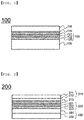
FIG. 1 is a vertical sectional view showing a pouch-shaped battery case according to an embodiment of the present invention. -
FIG. 2 is a vertical sectional view showing a pouch-shaped battery case according to another embodiment of the present invention. -
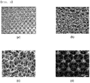
FIG. 3 is a view showing various structures, such as a net structure and a porous structure, of a heat dissipation layer. - Now, preferred embodiments of the present invention will be described in detail with reference to the accompanying drawings such that the preferred embodiments of the present invention can be easily implemented by a person having ordinary skill in the art to which the present invention pertains. In describing the principle of operation of the preferred embodiments of the present invention in detail, however, a detailed description of known functions and configurations incorporated herein will be omitted when the same may obscure the subject matter of the present invention.
- Wherever possible, the same reference numbers will be used throughout the drawings to refer to parts that perform similar functions or operations. Meanwhile, in the case in which one part is 'connected' to another part in the following description of the present invention, not only may the one part be directly connected to the another part, but also, the one part may be indirectly connected to the another part via a further part. In addition, that a certain element is 'included' means that other elements are not excluded, but may be further included unless mentioned otherwise.
- Reference will now be made in detail to the preferred embodiments of the present invention, examples of which are illustrated in the accompanying drawings.
-
FIG. 1 is a vertical sectional view schematically showing a pouch-shaped battery case according to an embodiment of the present invention. - Referring to
FIG. 1 , a pouch-shapedbattery case 100 is configured to have a structure in which anouter coating layer 110, a metal barrier layer 120, and an inneradhesive layer 130 are sequentially stacked and in which anadhesive layer 140 is disposed between theouter coating layer 110 and the metal barrier layer 120. Although not shown inFIG. 1 , theadhesive layer 140 may be disposed between the metal barrier layer 120 and the inneradhesive layer 130. Alternatively, theadhesive layer 140 may be disposed both between theouter coating layer 110 and the metal barrier layer 120 and between the metal barrier layer 120 and the inneradhesive layer 130. - The metal barrier layer 120 is configured to have a structure in which a
first metal layer 121, a heat dissipation layer 122, and asecond metal layer 123 are stacked. The first metal layer and the second metal layer may be made of the same material or different materials. The heat dissipation layer 122 may be made of the same material as thefirst metal layer 121 or thesecond metal layer 123 or a different material than thefirst metal layer 121 or thesecond metal layer 123. - The heat dissipation layer 122 has openings formed therein, which will be described later with reference to
FIG. 3 . The openings formed in the heat dissipation layer 122 are filled with an adhesive material (not shown). When the first metal layer and the second metal layer are coupled to the heat dissipation layer, the first metal layer, the heat dissipation layer, and the second metal layer constitute a single member due to the adhesive material. -
FIG. 2 is a vertical sectional view schematically showing a pouch-shaped battery case according to another embodiment of the present invention. - Referring to
FIG. 2 , a pouch-shapedbattery case 200 is configured to have a structure in which a firstouter coating layer 211, a secondouter coating layer 212, ametal barrier layer 220, a first inner adhesive layer 231, and a second inneradhesive layer 232 are sequentially stacked and in which an adhesive layer 213 is disposed between the secondouter coating layer 212 and themetal barrier layer 220. Although not shown inFIG. 2 , the adhesive layer 213 may be disposed between themetal barrier layer 220 and the first inner adhesive layer 231. Alternatively, the adhesive layer 213 may be disposed both between the secondouter coating layer 212 and themetal barrier layer 220 and between the first inner adhesive layer 231 and themetal barrier layer 220. - In comparison between the pouch-shaped
battery case 100 and the pouch-shapedbattery case 200, the pouch-shapedbattery case 200 may have the same structure as the pouch-shapedbattery case 100 except that the pouch-shapedbattery case 200 includes a two-layered outer coating layer and a two-layered inner adhesive layer. Consequently, a description of the pouch-shapedbattery case 100 except for the above-described difference may be equally applied to the pouch-shapedbattery case 200. -
FIG. 3 is a view showing various structures, such as a net structure and a porous structure, of a heat dissipation layer. - Referring to
FIG. 3 , (a) ofFIG. 3 shows a heat dissipation layer configured to have a net structure including a plurality of through-holes formed in a flat metal sheet, and (b), (c), and (d) ofFIG. 3 show metal heat dissipation layers configured to have three-dimensional open type porous structures including pores. - The through-holes and the pores are filled with an adhesive material, by which the heat dissipation layers are coupled to metal layers. The adhesive material may fill the through-holes and the pores such that a volume ratio of the adhesive material to the through-holes and the pores ranges from 50% to 100%.
- Each of the heat dissipation layers may be made of a material that exhibits high thermal conductivity. In consideration of the fact that a metal layer of a laminate sheet is generally made of aluminum, each of the heat dissipation layers may be made of a metal material that exhibits higher thermal conductivity than aluminum.
- Since the pouch-shaped battery case according to the present invention includes a metal barrier layer configured to have a structure in which a heat dissipation layer is interposed between metal layers, as described above, it is possible to improve the formability and heat dissipation efficiency of the pouch-shaped battery case.
- Those skilled in the art to which the present invention pertains will appreciate that various applications and modifications are possible based on the above description, without departing from the scope of the present invention.
- As is apparent from the above description, the pouch-shaped battery case according to the present invention includes an outer coating layer, a metal barrier layer, and an inner adhesive layer, wherein the metal barrier layer includes a plurality of metal layers. Since each of the metal layers is thinner than a single metal layer having the same thickness, the pouch-shaped battery case may exhibit further improved flexibility, whereby it is possible to improve the formability of the pouch-shaped battery case.
- In addition, since a heat dissipation layer is disposed between the metal layers, the heat dissipation efficiency of the pouch-shaped battery case is improved in the state in which the metal layers are coupled to each other via the heat dissipation layer. Consequently, heat dissipation is rapidly achieved before a battery cell is deteriorated, whereby it is possible to provide a secondary battery having improved safety.
Claims (14)
- A pouch-shaped battery case configured to receive an electrode assembly configured to have a structure in which a positive electrode and a negative electrode are stacked in a state in which a separator is interposed between the positive electrode and the negative electrode, the pouch-shaped battery case comprising:an outer coating layer;a metal barrier layer; andan inner adhesive layer, whereinthe metal barrier layer comprises a plurality of metal layers and a heat dissipation layer interposed between the metal layers.
- The pouch-shaped battery case according to claim 1, wherein the metal barrier layer is configured to have a structure in which a first metal layer, the heat dissipation layer, and a second metal layer are sequentially stacked.
- The pouch-shaped battery case according to claim 1, wherein the heat dissipation layer is configured to have a net structure or a porous structure, in which openings formed in the heat dissipation layer are filled with an adhesive material.
- The pouch-shaped battery case according to claim 3, wherein the adhesive material is at least one selected from a group consisting of a polyester-based resin including polyethylene terephthalate, polybutylene terephthalate, polyethylene naphthalate, polybutylene naphthalate, polyethylene isophthalate, polycarbonate, or copolymer polyester; a polyester-based adhesive; a polyurethane-based adhesive; an epoxy-based resin; a phenol-based resin; nylon 6, nylon 66, or nylon 12; a polyamide-based resin; a polyolefin-based resin including polyolefin, carboxylic acid-modified polyolefin, or metal-modified polyolefin; a polyvinyl-acetate-based resin; a cellulose-based adhesive; a (meth)acryl-based resin; a polyimide-based resin; an amino resin including a urea resin or a melamine resin; rubber including chloroprene rubber, nitrile rubber, or styrene-butadiene rubber; and a silicone-based resin.
- The pouch-shaped battery case according to claim 1, wherein the heat dissipation layer is made of a material that exhibits same thermal conductivity as aluminum or a material that exhibits higher thermal conductivity than aluminum.
- The pouch-shaped battery case according to claim 5, wherein the heat dissipation layer is made of at least one selected from a group consisting of aluminum (Al), beryllium (Be), copper (Cu), silver (Ag), and gold (Au).
- The pouch-shaped battery case according to claim 2, wherein the first metal layer and the second metal layer are coupled to each other via the heat dissipation layer.
- The pouch-shaped battery case according to claim 1, wherein the inner adhesive layer comprises a first inner adhesive layer and a second inner adhesive layer.
- The pouch-shaped battery case according to claim 8, wherein
the first inner adhesive layer is a layer that is located adjacent to the metal layer, the first inner adhesive layer being made of acidified polypropylene (PPa), and
the second inner adhesive layer is a layer that is located outside the first inner adhesive layer, the second inner adhesive layer being made of polypropylene (PP). - The pouch-shaped battery case according to claim 1, wherein the outer coating layer comprises a first outer coating layer and a second outer coating layer.
- The pouch-shaped battery case according to claim 10, wherein
the first outer coating layer is an outermost layer, the first outer coating layer being made of polyethylene terephthalate (PET), and
the second outer coating layer is a layer that is located between the first outer coating layer and the metal layer, the second outer coating layer being made of oriented nylon. - The pouch-shaped battery case according to claim 1, wherein the metal barrier layer is configured to have a structure in which heat dissipation layers are disposed between three or more metal layers.
- The pouch-shaped battery case according to claim 1, wherein
an adhesive layer is interposed between the metal barrier layer and the outer coating layer, and
an acidified-polypropylene layer is coupled to a surface of the metal barrier layer that faces the adhesive layer. - A pouch-shaped secondary battery comprising a pouch-shaped battery case according to any one of claims 1 to 13.
Applications Claiming Priority (2)
| Application Number | Priority Date | Filing Date | Title |
|---|---|---|---|
| KR1020170120637A KR102335205B1 (en) | 2017-09-19 | 2017-09-19 | Pouch-Type Battery Case Comprising Heat Dissipation Layer |
| PCT/KR2018/007475 WO2019059502A1 (en) | 2017-09-19 | 2018-07-02 | Pouch type battery case comprising heat dissipation layer |
Publications (2)
| Publication Number | Publication Date |
|---|---|
| EP3579294A1 true EP3579294A1 (en) | 2019-12-11 |
| EP3579294A4 EP3579294A4 (en) | 2020-05-27 |
Family
ID=65810802
Family Applications (1)
| Application Number | Title | Priority Date | Filing Date |
|---|---|---|---|
| EP18857724.1A Pending EP3579294A4 (en) | 2017-09-19 | 2018-07-02 | Pouch type battery case comprising heat dissipation layer |
Country Status (6)
| Country | Link |
|---|---|
| US (1) | US11289751B2 (en) |
| EP (1) | EP3579294A4 (en) |
| JP (1) | JP7041796B2 (en) |
| KR (1) | KR102335205B1 (en) |
| CN (1) | CN110235270B (en) |
| WO (1) | WO2019059502A1 (en) |
Cited By (1)
| Publication number | Priority date | Publication date | Assignee | Title |
|---|---|---|---|---|
| EP3753729A4 (en) * | 2019-02-27 | 2021-12-22 | Lg Chem, Ltd. | Sheath for secondary battery and secondary battery comprising same |
Families Citing this family (3)
| Publication number | Priority date | Publication date | Assignee | Title |
|---|---|---|---|---|
| CN112002917A (en) * | 2019-05-27 | 2020-11-27 | 林怡妏 | Battery core and dry or semi-dry battery composed of same |
| WO2023249299A1 (en) * | 2022-06-21 | 2023-12-28 | 주식회사 엘지에너지솔루션 | Battery module frame |
| KR102537683B1 (en) * | 2022-10-27 | 2023-05-30 | 율촌화학 주식회사 | Laminated structure for a cell-type battery pouch having a plurality of metal layers and a pouch-type secondary battery using the same |
Family Cites Families (33)
| Publication number | Priority date | Publication date | Assignee | Title |
|---|---|---|---|---|
| US6207271B1 (en) * | 1998-03-18 | 2001-03-27 | Ntk Powerdex, Inc. | Packaging material for hermetically sealed batteries |
| JP2004342564A (en) * | 2003-05-19 | 2004-12-02 | Toyo Kohan Co Ltd | Sheath material for battery |
| JP2005183051A (en) * | 2003-12-16 | 2005-07-07 | Mitsubishi Electric Corp | Battery |
| KR100624950B1 (en) | 2004-10-18 | 2006-09-15 | 삼성에스디아이 주식회사 | Battery outer case having heat spreading layer and lithium polymer battery using it |
| KR101001320B1 (en) * | 2007-11-09 | 2010-12-14 | 주식회사 엘지화학 | Battery Cell Having Improved Thermal Stability and Middle or Large-sized Battery Module Employed with the Same |
| KR100998846B1 (en) * | 2007-11-21 | 2010-12-08 | 주식회사 엘지화학 | Battery Cell of Excellent Heat Dissipation Property and Middle or Large-sized Battery Module Employed with the Same |
| JP5159435B2 (en) * | 2008-05-28 | 2013-03-06 | 古河電池株式会社 | Laminate film and heating material package |
| JP5708110B2 (en) | 2011-03-23 | 2015-04-30 | 凸版印刷株式会社 | Exterior materials for lithium-ion batteries |
| EP2735441A4 (en) * | 2011-07-21 | 2014-07-23 | Hanwha Chemical Corp | Battery packaging material having heat-dissipating characteristics |
| JP5510410B2 (en) * | 2011-08-02 | 2014-06-04 | 株式会社Gsユアサ | battery |
| EP2772958B1 (en) * | 2011-10-25 | 2017-12-13 | Dai Nippon Printing Co., Ltd. | Packaging material for electrochemical cell |
| JP2014086361A (en) | 2012-10-26 | 2014-05-12 | Toray Advanced Film Co Ltd | Aluminum foil laminate sheet for secondary battery exterior material and secondary battery exterior material |
| JP2014182872A (en) | 2013-03-18 | 2014-09-29 | Uacj Corp | Sheath material for batteries, and aluminum foil |
| CN105556699B (en) * | 2013-09-20 | 2020-06-09 | 大日本印刷株式会社 | Packaging material for battery |
| JP6458338B2 (en) * | 2013-11-01 | 2019-01-30 | 凸版印刷株式会社 | Secondary battery exterior material, secondary battery, and secondary battery exterior material manufacturing method |
| CN104681749B (en) * | 2013-11-29 | 2018-11-02 | 神华集团有限责任公司 | battery, battery pack and vehicle |
| WO2015087901A1 (en) | 2013-12-11 | 2015-06-18 | 大日本印刷株式会社 | Packaging material for battery |
| JP5725224B1 (en) * | 2014-03-20 | 2015-05-27 | 大日本印刷株式会社 | Battery packaging materials |
| JP6446950B2 (en) * | 2014-09-25 | 2019-01-09 | 大日本印刷株式会社 | Battery packaging materials |
| JP6466124B2 (en) * | 2014-09-29 | 2019-02-06 | 大和ハウス工業株式会社 | Firing body and method for producing the same |
| KR101779156B1 (en) | 2014-12-16 | 2017-09-18 | 주식회사 엘지화학 | Pouch type secondary battery and method of fabricating the same |
| CN204558547U (en) | 2015-02-06 | 2015-08-12 | 江阴骏驰光电科技有限公司 | A kind of high explosion-proof lithium battery aluminum plastic film |
| KR102071929B1 (en) | 2015-03-17 | 2020-01-31 | 후아웨이 테크놀러지 컴퍼니 리미티드 | Method, device and system for transmitting information |
| WO2016158797A1 (en) * | 2015-03-27 | 2016-10-06 | 大日本印刷株式会社 | Packaging material for batteries, and battery |
| KR102318043B1 (en) * | 2015-04-22 | 2021-10-28 | 에스케이이노베이션 주식회사 | Secondary battery and battery module having the same |
| WO2016178117A1 (en) | 2015-05-06 | 2016-11-10 | Semiconductor Energy Laboratory Co., Ltd. | Secondary battery and electronic device |
| JP2017069203A (en) * | 2015-09-30 | 2017-04-06 | 大日本印刷株式会社 | Battery-packaging material and battery |
| KR20170045800A (en) * | 2015-10-20 | 2017-04-28 | 주식회사 엘지화학 | Electrode Current Collector for Secondary Battery having Polymer Resin Layer |
| KR102065089B1 (en) * | 2016-02-25 | 2020-01-10 | 주식회사 엘지화학 | Battery Case Including Adiabatic Layer And Battery Cell Comprising the Same |
| JP6458777B2 (en) * | 2016-06-29 | 2019-01-30 | 株式会社村田製作所 | Exterior materials and batteries |
| TWI629820B (en) * | 2017-04-17 | 2018-07-11 | 華碩電腦股份有限公司 | Packaging film for battery and manufacturing method thereof |
| CN207256988U (en) * | 2017-08-11 | 2018-04-20 | 东莞市天耀高分子材料科技有限公司 | A kind of lithium battery housing material |
| KR102334019B1 (en) * | 2017-10-17 | 2021-12-02 | 주식회사 엘지에너지솔루션 | Battery Case Comprising Multi-Metal Barrier and Battery Cell Comprising the Same |
-
2017
- 2017-09-19 KR KR1020170120637A patent/KR102335205B1/en active IP Right Grant
-
2018
- 2018-07-02 WO PCT/KR2018/007475 patent/WO2019059502A1/en unknown
- 2018-07-02 JP JP2019542145A patent/JP7041796B2/en active Active
- 2018-07-02 CN CN201880008349.6A patent/CN110235270B/en active Active
- 2018-07-02 EP EP18857724.1A patent/EP3579294A4/en active Pending
- 2018-07-02 US US16/478,680 patent/US11289751B2/en active Active
Cited By (1)
| Publication number | Priority date | Publication date | Assignee | Title |
|---|---|---|---|---|
| EP3753729A4 (en) * | 2019-02-27 | 2021-12-22 | Lg Chem, Ltd. | Sheath for secondary battery and secondary battery comprising same |
Also Published As
| Publication number | Publication date |
|---|---|
| KR20190032110A (en) | 2019-03-27 |
| CN110235270B (en) | 2022-08-26 |
| US20200280112A1 (en) | 2020-09-03 |
| WO2019059502A1 (en) | 2019-03-28 |
| US11289751B2 (en) | 2022-03-29 |
| JP2020507891A (en) | 2020-03-12 |
| KR102335205B1 (en) | 2021-12-03 |
| JP7041796B2 (en) | 2022-03-25 |
| CN110235270A (en) | 2019-09-13 |
| EP3579294A4 (en) | 2020-05-27 |
Similar Documents
| Publication | Publication Date | Title |
|---|---|---|
| US11545707B2 (en) | Battery case comprising various kinds of metal barrier layers and battery cell including the same | |
| US11289751B2 (en) | Pouch-shaped battery case comprising heat dissipation layer | |
| US9537173B2 (en) | Pouch type lithium secondary battery | |
| EP2811571B1 (en) | Secondary battery having improved energy density | |
| KR101508416B1 (en) | Pouch-type secondary battery | |
| US20170110712A1 (en) | Battery cell | |
| KR101984265B1 (en) | Pouch type secondary battery and method of fabricating the same | |
| US20200168855A1 (en) | Secondary Battery Comprising Injection-Molded Battery Case | |
| KR102630853B1 (en) | Pouch-Type Secondary Battery Having Heat Transfer Member | |
| EP2884558B1 (en) | Rechargeable battery | |
| CN209766478U (en) | Battery case, battery cell and battery pack | |
| KR101689749B1 (en) | Embossed pouch for secondary battery and a method of making the same | |
| KR20140032710A (en) | Method for preparing pouch-type secondary battery | |
| KR101472613B1 (en) | Middle or large sized battery pack and packaging method thereof | |
| KR20170045800A (en) | Electrode Current Collector for Secondary Battery having Polymer Resin Layer | |
| KR101456735B1 (en) | Middle or large sized battery pack and packaging method thereof | |
| KR20160071108A (en) | Pouch type secondary battery and method of fabricating the same | |
| WO2008054080A1 (en) | Battery module of improved safety against external impact | |
| KR102178726B1 (en) | A pouch case for a secondary battery and a pouch type secondary battery | |
| KR101464796B1 (en) | Middle or large sized battery pack and packaging method thereof | |
| KR101459405B1 (en) | Battery Pack Having Improved Safety | |
| KR102660400B1 (en) | Pouch film and secondary battery | |
| KR20140062294A (en) | Pouch for polymer cell and a method of making the same |
Legal Events
| Date | Code | Title | Description |
|---|---|---|---|
| STAA | Information on the status of an ep patent application or granted ep patent |
Free format text: STATUS: THE INTERNATIONAL PUBLICATION HAS BEEN MADE |
|
| PUAI | Public reference made under article 153(3) epc to a published international application that has entered the european phase |
Free format text: ORIGINAL CODE: 0009012 |
|
| STAA | Information on the status of an ep patent application or granted ep patent |
Free format text: STATUS: REQUEST FOR EXAMINATION WAS MADE |
|
| 17P | Request for examination filed |
Effective date: 20190906 |
|
| AK | Designated contracting states |
Kind code of ref document: A1 Designated state(s): AL AT BE BG CH CY CZ DE DK EE ES FI FR GB GR HR HU IE IS IT LI LT LU LV MC MK MT NL NO PL PT RO RS SE SI SK SM TR |
|
| AX | Request for extension of the european patent |
Extension state: BA ME |
|
| A4 | Supplementary search report drawn up and despatched |
Effective date: 20200423 |
|
| RIC1 | Information provided on ipc code assigned before grant |
Ipc: B32B 15/20 20060101ALI20200417BHEP Ipc: H01M 10/613 20140101ALI20200417BHEP Ipc: H01M 2/02 20060101AFI20200417BHEP Ipc: H01M 10/655 20140101ALI20200417BHEP Ipc: H01M 10/647 20140101ALI20200417BHEP |
|
| DAV | Request for validation of the european patent (deleted) | ||
| DAX | Request for extension of the european patent (deleted) | ||
| RAP1 | Party data changed (applicant data changed or rights of an application transferred) |
Owner name: LG ENERGY SOLUTION LTD. |
|
| RAP3 | Party data changed (applicant data changed or rights of an application transferred) |
Owner name: LG ENERGY SOLUTION, LTD. |
|
| STAA | Information on the status of an ep patent application or granted ep patent |
Free format text: STATUS: EXAMINATION IS IN PROGRESS |
|
| 17Q | First examination report despatched |
Effective date: 20230424 |