EP3579248A1 - Nozzle-type electron beam irradiation device - Google Patents
Nozzle-type electron beam irradiation device Download PDFInfo
- Publication number
- EP3579248A1 EP3579248A1 EP18748275.7A EP18748275A EP3579248A1 EP 3579248 A1 EP3579248 A1 EP 3579248A1 EP 18748275 A EP18748275 A EP 18748275A EP 3579248 A1 EP3579248 A1 EP 3579248A1
- Authority
- EP
- European Patent Office
- Prior art keywords
- electron beam
- nozzle
- vacuum nozzle
- vacuum
- irradiation device
- Prior art date
- Legal status (The legal status is an assumption and is not a legal conclusion. Google has not performed a legal analysis and makes no representation as to the accuracy of the status listed.)
- Granted
Links
Images



Classifications
-
- G—PHYSICS
- G21—NUCLEAR PHYSICS; NUCLEAR ENGINEERING
- G21K—HANDLING OF PARTICLES OR IONISING RADIATION NOT OTHERWISE PROVIDED FOR; IRRADIATION DEVICES; GAMMA RAY OR X-RAY MICROSCOPES
- G21K5/00—Irradiation devices
- G21K5/04—Irradiation devices with beam-forming means
-
- A—HUMAN NECESSITIES
- A61—MEDICAL OR VETERINARY SCIENCE; HYGIENE
- A61L—METHODS OR APPARATUS FOR STERILISING MATERIALS OR OBJECTS IN GENERAL; DISINFECTION, STERILISATION OR DEODORISATION OF AIR; CHEMICAL ASPECTS OF BANDAGES, DRESSINGS, ABSORBENT PADS OR SURGICAL ARTICLES; MATERIALS FOR BANDAGES, DRESSINGS, ABSORBENT PADS OR SURGICAL ARTICLES
- A61L2/00—Disinfection or sterilisation of materials or objects, in general; Accessories therefor
- A61L2/02—Disinfection or sterilisation of materials or objects, in general; Accessories therefor using physical processes
- A61L2/08—Radiation
-
- B—PERFORMING OPERATIONS; TRANSPORTING
- B65—CONVEYING; PACKING; STORING; HANDLING THIN OR FILAMENTARY MATERIAL
- B65B—MACHINES, APPARATUS OR DEVICES FOR, OR METHODS OF, PACKAGING ARTICLES OR MATERIALS; UNPACKING
- B65B55/00—Preserving, protecting or purifying packages or package contents in association with packaging
- B65B55/02—Sterilising, e.g. of complete packages
- B65B55/04—Sterilising wrappers or receptacles prior to, or during, packaging
-
- B—PERFORMING OPERATIONS; TRANSPORTING
- B65—CONVEYING; PACKING; STORING; HANDLING THIN OR FILAMENTARY MATERIAL
- B65B—MACHINES, APPARATUS OR DEVICES FOR, OR METHODS OF, PACKAGING ARTICLES OR MATERIALS; UNPACKING
- B65B55/00—Preserving, protecting or purifying packages or package contents in association with packaging
- B65B55/02—Sterilising, e.g. of complete packages
- B65B55/04—Sterilising wrappers or receptacles prior to, or during, packaging
- B65B55/08—Sterilising wrappers or receptacles prior to, or during, packaging by irradiation
-
- G—PHYSICS
- G21—NUCLEAR PHYSICS; NUCLEAR ENGINEERING
- G21K—HANDLING OF PARTICLES OR IONISING RADIATION NOT OTHERWISE PROVIDED FOR; IRRADIATION DEVICES; GAMMA RAY OR X-RAY MICROSCOPES
- G21K1/00—Arrangements for handling particles or ionising radiation, e.g. focusing or moderating
- G21K1/08—Deviation, concentration or focusing of the beam by electric or magnetic means
- G21K1/093—Deviation, concentration or focusing of the beam by electric or magnetic means by magnetic means
-
- G—PHYSICS
- G21—NUCLEAR PHYSICS; NUCLEAR ENGINEERING
- G21K—HANDLING OF PARTICLES OR IONISING RADIATION NOT OTHERWISE PROVIDED FOR; IRRADIATION DEVICES; GAMMA RAY OR X-RAY MICROSCOPES
- G21K5/00—Irradiation devices
- G21K5/10—Irradiation devices with provision for relative movement of beam source and object to be irradiated
-
- B—PERFORMING OPERATIONS; TRANSPORTING
- B65—CONVEYING; PACKING; STORING; HANDLING THIN OR FILAMENTARY MATERIAL
- B65B—MACHINES, APPARATUS OR DEVICES FOR, OR METHODS OF, PACKAGING ARTICLES OR MATERIALS; UNPACKING
- B65B3/00—Packaging plastic material, semiliquids, liquids or mixed solids and liquids, in individual containers or receptacles, e.g. bags, sacks, boxes, cartons, cans, or jars
- B65B3/02—Machines characterised by the incorporation of means for making the containers or receptacles
- B65B3/022—Making containers by moulding of a thermoplastic material
Definitions
- the present invention relates to a nozzle-type electron beam irradiation device.
- a nozzle-type electron beam irradiation device includes a vacuum nozzle that is connected to a vacuum chamber and emits an electron beam from the tip of the nozzle.
- the vacuum nozzle of the nozzle-type electron beam irradiation device is inserted into the opening of a container and an electron beam is emitted from the vacuum nozzle, thereby irradiating the inside of the container with the electron beam.
- An electron beam is emitted into the container, for example, to sterilize the inside of the container.
- the nozzle-type electron beam irradiation device sterilizes the inside of the container by direct irradiation of an electron beam, thereby suppressing deterioration of the container as well as power consumption as compared with an electron beam irradiation device that emits a strong electron beam into a container from the outside.
- a nozzle-type electron beam irradiation device In such a nozzle-type electron beam irradiation device, it is preferable that an electron beam guided into a vacuum nozzle hardly hits the inner surface of the vacuum nozzle. This is because an electron beam hitting the inner surface of the vacuum nozzle may not be emitted to the outside and cause a loss that reduces the yield of the electron beam.
- a nozzle-type electron beam irradiation device disclosed in the related art focuses an electron beam with an electrostatic lens provided in an electron beam generator (for example, see Patent Literature 1).
- Patent Literature 1 Japanese Patent No. 5597743
- an electron beam focusing mechanism may interrupt the insertion of the vacuum nozzle into the opening of a container, preventing the inside of the container (an irradiation object having an opening) from being properly irradiated with an electron beam.
- An object of the present invention is to provide a nozzle-type electron beam irradiation device that can achieve a long life with a simple configuration and properly emit an electron beam into an irradiation object having an opening.
- a nozzle-type electron beam irradiation device includes a vacuum nozzle insertable into the opening of an irradiation object, the opening being formed on the irradiation object, the irradiation device emitting an electron beam into the irradiation object through the vacuum nozzle, the nozzle-type electron beam irradiation device including a vacuum chamber and an electron beam generator disposed in the vacuum chamber, the vacuum nozzle being connected to the vacuum chamber so as to guide an electron beam from the electron beam generator and emit the electron beam to the outside, the nozzle-type electron beam irradiation device including:
- a nozzle-type electron beam irradiation device includes, in the nozzle-type electron beam irradiation device according to the first invention, a connecting member connecting the vacuum chamber and the vacuum nozzle, the connecting member containing the neodymium magnet inside the connecting member.
- the vacuum nozzle in the nozzle-type electron beam irradiation device according to the second invention is disposed with a base end embedded in the connecting member, and the cooling mechanism includes a coolant passage that allows the passage of a coolant, the coolant passage being disposed between the vacuum nozzle and the neodymium magnet so as to surround the vacuum nozzle in the connecting member.
- the nozzle-type electron beam irradiation device is applicable even if an electron beam is generated with low power, achieving a long life. Furthermore, another cooling mechanism for cooling the neodymium magnet is not necessary, achieving a simple configuration. Additionally, the electron beam is emitted into the irradiation object while the vacuum nozzle is inserted and removed into and from the opening of the irradiation object without being interrupted by the neodymium magnet. This can properly emit an electron beam into the irradiation object.
- a nozzle-type electron beam irradiation device 1 according to the present embodiment will be described in detail below.
- the nozzle-type electron beam irradiation device 1 includes a vacuum nozzle 2 insertable into an opening m of an irradiation object O, the opening m being formed on the irradiation object O.
- An electron beam E is emitted into the irradiation object O through the vacuum nozzle 2.
- the irradiation object O having the opening m is, for example, a container such as a PET bottle or a preform.
- the preform is a material form shaped like a test tube before being molded into a PET bottle by blow molding.
- the irradiation object O having the opening m will be discussed as a PET bottle O.
- the nozzle-type electron beam irradiation device 1 includes a vacuum chamber 3 and an electron beam generator 4 disposed in the vacuum chamber 3.
- the electron beam generator 4 may be provided with an electrostatic lens 5 that focuses the electron beam E from the electron beam generator 4.
- the vacuum nozzle 2 is connected to the vacuum chamber 3 so as to guide the electron beam E from the electron beam generator 4 and emit the electron beam E to the outside.
- the inside of the vacuum chamber 3 is evacuated so as to accelerate the electron beam E from the electron beam generator 4.
- the electron beam generator 4 includes, for example, a component like a cathode for generating the electron beam E.
- the vacuum nozzle 2 has an exit window 20 made of, for example, titanium foil at the tip of the nozzle in order to emit the electron beam E to the outside. If the electrostatic lens 5 is provided in the electron beam generator 4, the electrostatic lens 5 is disposed so as to guide the electron beam E from the electron beam generator 4 into the vacuum nozzle 2.
- the degree of focusing of the electron beam E greatly changes according to the position of a component (e.g., a cathode) for generating the electron beam E, for example, a distance between the cathode and the electrostatic lens 5. Even if the position (distance) is properly set, in the case of the long vacuum nozzle 2, the electron beam E hits the inner surface of the vacuum nozzle 2 before reaching the tip of the vacuum nozzle 2.
- a neodymium magnet 60 for focusing the electron beam E guided by the vacuum nozzle 2 is disposed outside the vacuum nozzle 2 so as not to interfere with the electron beam E.
- a neodymium magnet has a stronger magnetic force than other permanent magnets and thus can be smaller in size than other permanent magnets.
- the neodymium magnet 60 is shaped so as to surround the vacuum nozzle 2 from the outside ( FIG. 1 illustrates only a half of the magnet to enhance ease of seeing).
- the neodymium magnet 60 is located at a place where the neodymium magnet 60 does not interrupt the insertion of the vacuum nozzle 2 into the opening m of the PET bottle O, for example, a base end of the vacuum nozzle 2.
- the neodymium magnet 60 is disposed with a vacuum-chamber side 60N serving as the north pole (or the south pole) and a PET-bottle side 60S serving as the south pole (or the north pole).
- the nozzle-type electron beam irradiation device 1 further includes an inserting/removing mechanism 7 that inserts and removes the vacuum nozzle 2 into and from the opening m of the PET bottle O, and a cooling mechanism 8 that cools the vacuum nozzle 2.
- the inserting/removing mechanism 7 may be, for example, a PET bottle elevator 7 that moves up and down the PET bottle O, but is not particularly limited as long as the vacuum nozzle 2 is inserted and removed into and from the opening m of the PET bottle O.
- the PET bottle elevator 7 lifts the PET bottle O so as to insert the tip (exit window 20) of the vacuum nozzle 2 into the PET bottle O from the opening m and then moves down the PET bottle O from the state so as to remove the tip of the vacuum nozzle 2 from the opening m of the PET bottle O.
- the PET bottle elevator 7 includes a gripper 71 that grips the PET bottle O, a guide member 72 that vertically guides the gripper 71, and an actuator (not shown) that vertically moves the gripper 71 according to the guide of the guide member 72.
- the inserting/removing mechanism 7 may move up and down the vacuum nozzle 2 unlike the PET bottle elevator 7 that moves up and down the PET bottle O.
- the cooling mechanism 8 cools the vacuum nozzle 2, which rises in temperature while guiding the electron beam E, to a proper temperature.
- the cooling mechanism 8 is provided with, for example, a coolant passage 83 surrounding the vacuum nozzle 2 and a coolant introducing portion 81 that allows the passage of a coolant through the coolant passage 83.
- the coolant passage 83 allows the passage of one of a liquid and gaseous coolant therein, so that the coolant absorbs heat from the vacuum nozzle 2.
- the neodymium magnet 60 advantageously has a stronger magnetic force than other permanent magnets but disadvantageously tends to be irreversibly demagnetized by heat.
- the cooling mechanism 8 cools the neodymium magnet 60 so as to prevent irreversible demagnetization while cooling the vacuum nozzle 2. This eliminates the need for another cooling mechanism for cooling the neodymium magnet 60.
- the electron beam E from the electron beam generator 4 disposed in the vacuum chamber 3 is guided into the vacuum nozzle 2 and then is emitted from the exit window 20 of the vacuum nozzle 2 to the outside.
- the electrostatic lens 5 is provided, the electron beam E is focused through the electrostatic lens 5 before being guided into the vacuum nozzle 2.
- the electron beam E guided into the vacuum nozzle 2 is focused by the neodymium magnet 60 surrounding the vacuum nozzle 2 from the outside. This reduces the dose of the electron beam E hitting the inner surface of the vacuum nozzle 2, leading to a smaller loss of the electron beam E emitted to the outside.
- the yield of the electron beam E increases, achieving applicability even if the electron beam E is generated with low power by the electron beam generator 4.
- the PET bottle elevator 7 inserts and/or removes the vacuum nozzle 2 into and/or from the opening m of the PET bottle O, the electron beam E is emitted into the PET bottle O.
- the neodymium magnet 60 that can be small in size does not interrupt the insertion and removal.
- the nozzle-type electron beam irradiation device 1 is applicable even if the electron beam E is generated with low power, achieving a long life. Furthermore, another cooling mechanism for cooling the neodymium magnet 60 is not necessary, achieving a simple configuration. Additionally, the electron beam E is emitted into the PET bottle O while the vacuum nozzle 2 is inserted and removed into and from the opening m of the PET bottle O without being interrupted by the neodymium magnet 60. This can properly emit the electron beam E into the PET bottle O.
- the nozzle-type electron beam irradiation device 1 according to the embodiment will be more specifically described according to Examples 1 and 2.
- the neodymium magnet 60, a configuration near the neodymium magnet 60, and the cooling mechanism 8 will be more specifically described.
- Other configurations are identical to those of the embodiment and thus the explanation thereof is omitted.
- Example 1 the nozzle-type electron beam irradiation device 1 according to Example 1 will be described in detail below.
- the nozzle-type electron beam irradiation device 1 includes a connecting member 11 that is a circular mount connecting the vacuum chamber 3 and the vacuum nozzle 2 ( FIG. 2 illustrates only a half of the connecting member to enhance ease of seeing).
- the connecting member 11 fixes the vacuum chamber 3 on one side and fixes the embedded base end of the vacuum nozzle 2 on the other side, thereby structurally stabilizing the vacuum chamber 3 and the vacuum nozzle 2.
- a storage groove 16 that stores the neodymium magnet 60 is formed from the other side of the connecting member 11.
- the connecting member 11 further includes a lid plate 12 for fixing the neodymium magnet 60 stored in the storage groove 16 (that is, held in the storage groove 16). As illustrated in FIG.
- the storage groove 16 is identical to the neodymium magnet 60 in plan view and has a depth equivalent to the thickness of the neodymium magnet 60 and the lid plate 12.
- the lid plate 12 is identical to the neodymium magnet 60 and the storage groove 16 in plan view.
- the neodymium magnet 60 need not be a single magnet as illustrated in FIG. 3 , and may include multiple neodymium magnets in the thickness direction. Thus, a magnetic force for focusing the electron beam E can be adjusted by increasing or reducing the number of neodymium magnets 60 stored in the storage groove 16.
- the cooling mechanism 8 of the nozzle-type electron beam irradiation device 1 according to Example 1 is a water-cooling mechanism that includes, as illustrated in FIG. 2 , the coolant passage 83 surrounding the vacuum nozzle 2, the coolant introducing portion 81 that allows the introduction of a coolant (water) into the coolant passage 83, and a coolant collecting portion 89 from which the coolant introduced into the coolant passage 83 is collected.
- the coolant passage 83 includes, as a portion for introducing a coolant to the outer edge of the tip of the vacuum nozzle 2, an introducing tube 82 that introduces the coolant from the coolant introducing portion 81 into the connecting member 11, an internal introducing passage 84 that introduces the coolant into one semicircular portion on the outer periphery of the base end of the vacuum nozzle 2 in the connecting member 11, and an external introducing passage 85 that introduces the coolant from the internal introducing passage 84 to the outer edge of the tip of the vacuum nozzle 2 (one semicircular portion) outside the connecting member 11.
- the coolant passage 83 includes, as a portion for collecting a coolant from the outer edge of the tip of the vacuum nozzle 2, an external collecting passage 86 that collects the coolant from the outer edge (the other semicircular portion) of the tip of the vacuum nozzle 2 to the inside of the connecting member 11, an internal collecting passage 87 that collects the coolant from the other semicircular portion on the outer periphery of the base end of the vacuum nozzle 2 in the connecting member 11, and a collecting tube 88 that collects the coolant from the inside of the connecting member 11 to the coolant collecting portion 89.
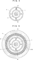
- the cooling mechanism 8 has an external cylinder 21 that is disposed so as to leave a clearance from the vacuum nozzle 2 on the outer periphery of the vacuum nozzle 2. Moreover, in order to prevent a coolant introduced into the outer edge of the tip of the vacuum nozzle 2 from flowing out of the vacuum nozzle 2, the cooling mechanism 8 further includes a tip member 22 connecting the tip end of the external cylinder 21 and the tip of the vacuum nozzle 2. As illustrated in FIG. 4 (a cross-sectional view taken along line A-A of FIG.
- the clearance between the vacuum nozzle 2 and the external cylinder 21 corresponds to the external introducing passage 85 and the external collecting passage 86, and two partitions 23 separating the external introducing passage 85 and the external collecting passage 86 except for the outer edge of the tip of the vacuum nozzle 2 are disposed in the clearance.
- FIG. 5 a cross-sectional view taken along line B-B of FIG. 2
- the partitions 23 are extended so as to separate one semicircular portion and the other semicircular portion on the outer periphery of the base end of the vacuum nozzle 2.
- the coolant passage 83 (specifically, portions separated by the partitions 23 in the internal introducing passage 84 and the internal collecting passage 87) is disposed between the vacuum nozzle 2 and the neodymium magnet 60 so as to surround the vacuum nozzle 2.
- the connecting member 11 structurally stabilizes the vacuum chamber 3 and the vacuum nozzle 2. This prevents a change of the relative positions of the vacuum chamber 3 and the vacuum nozzle 2 even on a movable member, e.g., a turntable.
- the neodymium magnet 60 is held in the connecting member 11 and thus is located near the electron beam generator 4 without interrupting the insertion and removal of the vacuum nozzle 2 into and from the opening m of the PET bottle O.
- the coolant passage 83 substantially cools the overall vacuum nozzle 2 from the outer periphery (see FIGS. 4 and 5 ) and substantially cools the overall neodymium magnet 60 from the inner periphery (see FIG. 5 ).
- the nozzle-type electron beam irradiation device 1 does not change the relative positions of the vacuum chamber 3 and the vacuum nozzle 2 in addition to the effect of the embodiment, thereby properly emitting the electron beam E into the PET bottle O.
- the neodymium magnet 60 is located near the electron beam generator 4, promoting the focusing of the electron beam E. This achieves applicability even if the electron beam E is generated with lower power, thereby further extending the life of the device. Furthermore, the electron beam E is emitted into the PET bottle O while the vacuum nozzle 2 is inserted and removed into and from the opening m of the PET bottle O without being interrupted by the neodymium magnet 60. This can more properly emit the electron beam E into the PET bottle O.
- the coolant passage 83 substantially entirely cools the vacuum nozzle 2 and the neodymium magnet 60. This efficiently cools the vacuum nozzle 2 and the neodymium magnet 60, thereby further extending the life of the overall device.
- Example 2 the nozzle-type electron beam irradiation device 1 according to Example 2 will be described in detail below.
- Example 1 the cooling mechanism 8 is a water-cooling mechanism, whereas in Example 2, the cooling mechanism 8 is an air-cooling mechanism.
- Example 2 differences from Example 1 will be mainly described. The same configurations as those of Example 1 are indicated by the same reference numerals and the explanation thereof is omitted.
- the external introducing passage 85 where a coolant (water) is introduced from the base end to the tip end and the external collecting passage 86 where the coolant is collected from the tip end to the base end are divided by the partitions 23 on the outer periphery of the vacuum nozzle 2 (between the vacuum nozzle 2 and the external cylinder 21).
- the nozzle-type electron beam irradiation device 1 according to Example 2 is not provided with the partitions 23.
- a coolant nitrogen gas indicated by black arrows in FIG.
- the external cylinder 21 is extended so as to project from the tip of the vacuum nozzle 2 and the tip member 22 is inclined to the exit window 20 leaving a clearance from the vacuum nozzle 2.
- a part where a coolant is introduced from the outer periphery of the base end of the vacuum nozzle 2 and impinges on the exit window 20 corresponds to the external introducing passage 85. Since a coolant is discharged out of the nozzle-type electron beam irradiation device 1 according to Example 2, the configurations 86 to 89 for collecting the coolant according to Example 1 are not necessary.
- the overall configuration of the nozzle-type electron beam irradiation device 1 according to Example 2 can be further simplified in addition to the effect of the embodiment because the cooling mechanism 8 is an air-cooling mechanism.
- the coolant passage 83 (specifically, the external introducing passage 85) substantially entirely cools the vacuum nozzle 2 and the neodymium magnet 60. This efficiently cools the vacuum nozzle 2 and the neodymium magnet 60, thereby further extending the life of the overall device.
- connection member 11 according to Example 1 may be used for the nozzle-type electron beam irradiation device 1 according to Example 2.
- the shape of the neodymium magnet 60 is circular (annular) in the embodiment and Examples 1 and 2 but is not limited thereto.
- the neodymium magnet 60 may have any shape surrounding the vacuum nozzle 2, e.g., a square shape.
- the coolant is water in Example 1 but is not limited thereto. Any liquid is applicable as long as heat is absorbed and transferred from the vacuum nozzle 2 and the neodymium magnet 60.
- the coolant is nitrogen gas in Example 2 but is not limited thereto. Any gas is applicable as long as heat is absorbed and transferred from the vacuum nozzle 2 and the neodymium magnet 60.
Landscapes
- Engineering & Computer Science (AREA)
- Physics & Mathematics (AREA)
- General Engineering & Computer Science (AREA)
- High Energy & Nuclear Physics (AREA)
- Health & Medical Sciences (AREA)
- General Health & Medical Sciences (AREA)
- Mechanical Engineering (AREA)
- Spectroscopy & Molecular Physics (AREA)
- Toxicology (AREA)
- Epidemiology (AREA)
- Life Sciences & Earth Sciences (AREA)
- Animal Behavior & Ethology (AREA)
- Public Health (AREA)
- Veterinary Medicine (AREA)
- Apparatus For Disinfection Or Sterilisation (AREA)
Abstract
Description
- The present invention relates to a nozzle-type electron beam irradiation device.
- A nozzle-type electron beam irradiation device includes a vacuum nozzle that is connected to a vacuum chamber and emits an electron beam from the tip of the nozzle. With this configuration, the vacuum nozzle of the nozzle-type electron beam irradiation device is inserted into the opening of a container and an electron beam is emitted from the vacuum nozzle, thereby irradiating the inside of the container with the electron beam. An electron beam is emitted into the container, for example, to sterilize the inside of the container. In this case, the nozzle-type electron beam irradiation device sterilizes the inside of the container by direct irradiation of an electron beam, thereby suppressing deterioration of the container as well as power consumption as compared with an electron beam irradiation device that emits a strong electron beam into a container from the outside.
- In such a nozzle-type electron beam irradiation device, it is preferable that an electron beam guided into a vacuum nozzle hardly hits the inner surface of the vacuum nozzle. This is because an electron beam hitting the inner surface of the vacuum nozzle may not be emitted to the outside and cause a loss that reduces the yield of the electron beam. A nozzle-type electron beam irradiation device disclosed in the related art focuses an electron beam with an electrostatic lens provided in an electron beam generator (for example, see Patent Literature 1).
- Patent Literature 1: Japanese Patent No.
5597743 - In the nozzle-type electron beam irradiation device described in
Patent Literature 1, although an electron beam is focused through the electrostatic lens, the focusing may be insufficient in some cases. For example, in the case of a long vacuum nozzle, an electron beam may widely hit the inner surface of the vacuum nozzle until the electron beam reaches the tip of the vacuum nozzle, so that the yield of the electron beam may decrease. Thus, if an electron beam is generated with low power by the electron beam generator, the electron beam may not be sufficiently emitted from the vacuum nozzle. For this reason, it is necessary to generate an electron beam with high power in the electron beam generator, thereby shortening the life of a cathode in the electron beam generator. If an electron beam focusing mechanism is additionally provided, an electron beam is sufficiently focused but the configuration becomes complicated. Furthermore, the electron beam focusing mechanism may interrupt the insertion of the vacuum nozzle into the opening of a container, preventing the inside of the container (an irradiation object having an opening) from being properly irradiated with an electron beam. - An object of the present invention is to provide a nozzle-type electron beam irradiation device that can achieve a long life with a simple configuration and properly emit an electron beam into an irradiation object having an opening.
- In order to solve the problems, a nozzle-type electron beam irradiation device according to a first invention includes a vacuum nozzle insertable into the opening of an irradiation object, the opening being formed on the irradiation object, the irradiation device emitting an electron beam into the irradiation object through the vacuum nozzle,
the nozzle-type electron beam irradiation device including a vacuum chamber and an electron beam generator disposed in the vacuum chamber,
the vacuum nozzle being connected to the vacuum chamber so as to guide an electron beam from the electron beam generator and emit the electron beam to the outside,
the nozzle-type electron beam irradiation device including: - a neodymium magnet that surrounds the vacuum nozzle from the outside and focuses the electron beam guided into the vacuum nozzle;
- an inserting/removing mechanism that inserts and removes the vacuum nozzle into and from the opening of the irradiation object; and
- a cooling mechanism that cools the vacuum nozzle,
- the cooling mechanism cooling the neodymium magnet so as to prevent irreversible demagnetization while cooling the vacuum nozzle.
- A nozzle-type electron beam irradiation device according to a second invention includes, in the nozzle-type electron beam irradiation device according to the first invention, a connecting member connecting the vacuum chamber and the vacuum nozzle,
the connecting member containing the neodymium magnet inside the connecting member. - In a nozzle-type electron beam irradiation device according to a third invention, the vacuum nozzle in the nozzle-type electron beam irradiation device according to the second invention is disposed with a base end embedded in the connecting member, and
the cooling mechanism includes a coolant passage that allows the passage of a coolant,
the coolant passage being disposed between the vacuum nozzle and the neodymium magnet so as to surround the vacuum nozzle in the connecting member. - The nozzle-type electron beam irradiation device is applicable even if an electron beam is generated with low power, achieving a long life. Furthermore, another cooling mechanism for cooling the neodymium magnet is not necessary, achieving a simple configuration. Additionally, the electron beam is emitted into the irradiation object while the vacuum nozzle is inserted and removed into and from the opening of the irradiation object without being interrupted by the neodymium magnet. This can properly emit an electron beam into the irradiation object.
-
- [
FIG. 1] FIG. 1 is a schematic longitudinal section illustrating a nozzle-type electron beam irradiation device according to an embodiment of the present invention. - [
FIG. 2] FIG. 2 is a schematic longitudinal section illustrating the nozzle-type electron beam irradiation device according to Example 1 of the present invention. - [
FIG. 3] FIG. 3 is an exploded perspective view of the nozzle-type electron beam irradiation device viewed from a PET bottle. - [
FIG. 4] FIG. 4 is a cross-sectional view taken along line A-A ofFIG. 2 . - [
FIG. 5] FIG. 5 is a cross-sectional view taken along line B-B ofFIG. 2 . - [
FIG. 6] FIG. 6 is a schematic longitudinal section illustrating the nozzle-type electron beam irradiation device according to Example 2 of the present invention. - Referring to
FIG. 1 , a nozzle-type electronbeam irradiation device 1 according to the present embodiment will be described in detail below. - As illustrated in
FIG. 1 , the nozzle-type electronbeam irradiation device 1 includes avacuum nozzle 2 insertable into an opening m of an irradiation object O, the opening m being formed on the irradiation object O. An electron beam E is emitted into the irradiation object O through thevacuum nozzle 2. In this case, the irradiation object O having the opening m is, for example, a container such as a PET bottle or a preform. The preform is a material form shaped like a test tube before being molded into a PET bottle by blow molding. For simplicity, the irradiation object O having the opening m will be discussed as a PET bottle O. - The nozzle-type electron
beam irradiation device 1 includes avacuum chamber 3 and anelectron beam generator 4 disposed in thevacuum chamber 3. Theelectron beam generator 4 may be provided with anelectrostatic lens 5 that focuses the electron beam E from theelectron beam generator 4. Thevacuum nozzle 2 is connected to thevacuum chamber 3 so as to guide the electron beam E from theelectron beam generator 4 and emit the electron beam E to the outside. - The inside of the
vacuum chamber 3 is evacuated so as to accelerate the electron beam E from theelectron beam generator 4. Theelectron beam generator 4 includes, for example, a component like a cathode for generating the electron beam E. Thevacuum nozzle 2 has anexit window 20 made of, for example, titanium foil at the tip of the nozzle in order to emit the electron beam E to the outside. If theelectrostatic lens 5 is provided in theelectron beam generator 4, theelectrostatic lens 5 is disposed so as to guide the electron beam E from theelectron beam generator 4 into thevacuum nozzle 2. - In this case, the degree of focusing of the electron beam E greatly changes according to the position of a component (e.g., a cathode) for generating the electron beam E, for example, a distance between the cathode and the
electrostatic lens 5. Even if the position (distance) is properly set, in the case of thelong vacuum nozzle 2, the electron beam E hits the inner surface of thevacuum nozzle 2 before reaching the tip of thevacuum nozzle 2. Hence, as a gist of the present invention, aneodymium magnet 60 for focusing the electron beam E guided by thevacuum nozzle 2 is disposed outside thevacuum nozzle 2 so as not to interfere with the electron beam E. Generally, a neodymium magnet has a stronger magnetic force than other permanent magnets and thus can be smaller in size than other permanent magnets. - The
neodymium magnet 60 is shaped so as to surround thevacuum nozzle 2 from the outside (FIG. 1 illustrates only a half of the magnet to enhance ease of seeing). Theneodymium magnet 60 is located at a place where theneodymium magnet 60 does not interrupt the insertion of thevacuum nozzle 2 into the opening m of the PET bottle O, for example, a base end of thevacuum nozzle 2. Moreover, theneodymium magnet 60 is disposed with a vacuum-chamber side 60N serving as the north pole (or the south pole) and a PET-bottle side 60S serving as the south pole (or the north pole). - The nozzle-type electron
beam irradiation device 1 further includes an inserting/removingmechanism 7 that inserts and removes thevacuum nozzle 2 into and from the opening m of the PET bottle O, and acooling mechanism 8 that cools thevacuum nozzle 2. - The inserting/removing
mechanism 7 may be, for example, aPET bottle elevator 7 that moves up and down the PET bottle O, but is not particularly limited as long as thevacuum nozzle 2 is inserted and removed into and from the opening m of the PET bottle O. ThePET bottle elevator 7 lifts the PET bottle O so as to insert the tip (exit window 20) of thevacuum nozzle 2 into the PET bottle O from the opening m and then moves down the PET bottle O from the state so as to remove the tip of thevacuum nozzle 2 from the opening m of the PET bottle O. For this operation, thePET bottle elevator 7 includes agripper 71 that grips the PET bottle O, aguide member 72 that vertically guides thegripper 71, and an actuator (not shown) that vertically moves thegripper 71 according to the guide of theguide member 72. The inserting/removingmechanism 7 may move up and down thevacuum nozzle 2 unlike thePET bottle elevator 7 that moves up and down the PET bottle O. - The
cooling mechanism 8 cools thevacuum nozzle 2, which rises in temperature while guiding the electron beam E, to a proper temperature. Hence, thecooling mechanism 8 is provided with, for example, acoolant passage 83 surrounding thevacuum nozzle 2 and acoolant introducing portion 81 that allows the passage of a coolant through thecoolant passage 83. Thecoolant passage 83 allows the passage of one of a liquid and gaseous coolant therein, so that the coolant absorbs heat from thevacuum nozzle 2. In this configuration, theneodymium magnet 60 advantageously has a stronger magnetic force than other permanent magnets but disadvantageously tends to be irreversibly demagnetized by heat. Thus, thecooling mechanism 8 cools theneodymium magnet 60 so as to prevent irreversible demagnetization while cooling thevacuum nozzle 2. This eliminates the need for another cooling mechanism for cooling theneodymium magnet 60. - With this configuration, the electron beam E from the
electron beam generator 4 disposed in thevacuum chamber 3 is guided into thevacuum nozzle 2 and then is emitted from theexit window 20 of thevacuum nozzle 2 to the outside. If theelectrostatic lens 5 is provided, the electron beam E is focused through theelectrostatic lens 5 before being guided into thevacuum nozzle 2. The electron beam E guided into thevacuum nozzle 2 is focused by theneodymium magnet 60 surrounding thevacuum nozzle 2 from the outside. This reduces the dose of the electron beam E hitting the inner surface of thevacuum nozzle 2, leading to a smaller loss of the electron beam E emitted to the outside. Thus, the yield of the electron beam E increases, achieving applicability even if the electron beam E is generated with low power by theelectron beam generator 4. - While the
PET bottle elevator 7 inserts and/or removes thevacuum nozzle 2 into and/or from the opening m of the PET bottle O, the electron beam E is emitted into the PET bottle O. In this case, theneodymium magnet 60 that can be small in size does not interrupt the insertion and removal. - In this way, the nozzle-type electron
beam irradiation device 1 is applicable even if the electron beam E is generated with low power, achieving a long life. Furthermore, another cooling mechanism for cooling theneodymium magnet 60 is not necessary, achieving a simple configuration. Additionally, the electron beam E is emitted into the PET bottle O while thevacuum nozzle 2 is inserted and removed into and from the opening m of the PET bottle O without being interrupted by theneodymium magnet 60. This can properly emit the electron beam E into the PET bottle O. - The nozzle-type electron
beam irradiation device 1 according to the embodiment will be more specifically described according to Examples 1 and 2. In Examples 1 and 2, theneodymium magnet 60, a configuration near theneodymium magnet 60, and thecooling mechanism 8 will be more specifically described. Other configurations are identical to those of the embodiment and thus the explanation thereof is omitted. - Referring to
FIGS. 2 to 5 , the nozzle-type electronbeam irradiation device 1 according to Example 1 will be described in detail below. - As illustrated in
FIG. 2 , the nozzle-type electronbeam irradiation device 1 according to Example 1 includes a connectingmember 11 that is a circular mount connecting thevacuum chamber 3 and the vacuum nozzle 2 (FIG. 2 illustrates only a half of the connecting member to enhance ease of seeing). The connectingmember 11 fixes thevacuum chamber 3 on one side and fixes the embedded base end of thevacuum nozzle 2 on the other side, thereby structurally stabilizing thevacuum chamber 3 and thevacuum nozzle 2. Furthermore, astorage groove 16 that stores theneodymium magnet 60 is formed from the other side of the connectingmember 11. The connectingmember 11 further includes alid plate 12 for fixing theneodymium magnet 60 stored in the storage groove 16 (that is, held in the storage groove 16). As illustrated inFIG. 3 , thestorage groove 16 is identical to theneodymium magnet 60 in plan view and has a depth equivalent to the thickness of theneodymium magnet 60 and thelid plate 12. Thelid plate 12 is identical to theneodymium magnet 60 and thestorage groove 16 in plan view. Theneodymium magnet 60 need not be a single magnet as illustrated inFIG. 3 , and may include multiple neodymium magnets in the thickness direction. Thus, a magnetic force for focusing the electron beam E can be adjusted by increasing or reducing the number ofneodymium magnets 60 stored in thestorage groove 16. - The
cooling mechanism 8 of the nozzle-type electronbeam irradiation device 1 according to Example 1 is a water-cooling mechanism that includes, as illustrated inFIG. 2 , thecoolant passage 83 surrounding thevacuum nozzle 2, thecoolant introducing portion 81 that allows the introduction of a coolant (water) into thecoolant passage 83, and acoolant collecting portion 89 from which the coolant introduced into thecoolant passage 83 is collected. - The
coolant passage 83 includes, as a portion for introducing a coolant to the outer edge of the tip of thevacuum nozzle 2, an introducingtube 82 that introduces the coolant from thecoolant introducing portion 81 into the connectingmember 11, an internal introducingpassage 84 that introduces the coolant into one semicircular portion on the outer periphery of the base end of thevacuum nozzle 2 in the connectingmember 11, and an external introducingpassage 85 that introduces the coolant from the internal introducingpassage 84 to the outer edge of the tip of the vacuum nozzle 2 (one semicircular portion) outside the connectingmember 11. Thecoolant passage 83 includes, as a portion for collecting a coolant from the outer edge of the tip of thevacuum nozzle 2, anexternal collecting passage 86 that collects the coolant from the outer edge (the other semicircular portion) of the tip of thevacuum nozzle 2 to the inside of the connectingmember 11, aninternal collecting passage 87 that collects the coolant from the other semicircular portion on the outer periphery of the base end of thevacuum nozzle 2 in the connectingmember 11, and a collectingtube 88 that collects the coolant from the inside of the connectingmember 11 to thecoolant collecting portion 89. - In order to form the external introducing
passage 85 and theexternal collecting passage 86, thecooling mechanism 8 has anexternal cylinder 21 that is disposed so as to leave a clearance from thevacuum nozzle 2 on the outer periphery of thevacuum nozzle 2. Moreover, in order to prevent a coolant introduced into the outer edge of the tip of thevacuum nozzle 2 from flowing out of thevacuum nozzle 2, thecooling mechanism 8 further includes atip member 22 connecting the tip end of theexternal cylinder 21 and the tip of thevacuum nozzle 2. As illustrated inFIG. 4 (a cross-sectional view taken along line A-A ofFIG. 2 ), the clearance between thevacuum nozzle 2 and theexternal cylinder 21 corresponds to the external introducingpassage 85 and theexternal collecting passage 86, and twopartitions 23 separating the external introducingpassage 85 and theexternal collecting passage 86 except for the outer edge of the tip of thevacuum nozzle 2 are disposed in the clearance. As illustrated inFIG. 5 (a cross-sectional view taken along line B-B ofFIG. 2 ), also in the connectingmember 11, thepartitions 23 are extended so as to separate one semicircular portion and the other semicircular portion on the outer periphery of the base end of thevacuum nozzle 2. As is evident fromFIG. 5 , in the connectingmember 11, the coolant passage 83 (specifically, portions separated by thepartitions 23 in the internal introducingpassage 84 and the internal collecting passage 87) is disposed between thevacuum nozzle 2 and theneodymium magnet 60 so as to surround thevacuum nozzle 2. - With this configuration, as illustrated in
FIG. 2 , the connectingmember 11 structurally stabilizes thevacuum chamber 3 and thevacuum nozzle 2. This prevents a change of the relative positions of thevacuum chamber 3 and thevacuum nozzle 2 even on a movable member, e.g., a turntable. Moreover, theneodymium magnet 60 is held in the connectingmember 11 and thus is located near theelectron beam generator 4 without interrupting the insertion and removal of thevacuum nozzle 2 into and from the opening m of the PET bottle O. Furthermore, the coolant passage 83 (specifically, the internal introducingpassage 84, the external introducingpassage 85, theexternal collecting passage 86, and the internal collecting passage 87) substantially cools theoverall vacuum nozzle 2 from the outer periphery (seeFIGS. 4 and 5 ) and substantially cools theoverall neodymium magnet 60 from the inner periphery (seeFIG. 5 ). - As has been discussed, the nozzle-type electron
beam irradiation device 1 according to Example 1 does not change the relative positions of thevacuum chamber 3 and thevacuum nozzle 2 in addition to the effect of the embodiment, thereby properly emitting the electron beam E into the PET bottle O. - Moreover, the
neodymium magnet 60 is located near theelectron beam generator 4, promoting the focusing of the electron beam E. This achieves applicability even if the electron beam E is generated with lower power, thereby further extending the life of the device. Furthermore, the electron beam E is emitted into the PET bottle O while thevacuum nozzle 2 is inserted and removed into and from the opening m of the PET bottle O without being interrupted by theneodymium magnet 60. This can more properly emit the electron beam E into the PET bottle O. - Additionally, the
coolant passage 83 substantially entirely cools thevacuum nozzle 2 and theneodymium magnet 60. This efficiently cools thevacuum nozzle 2 and theneodymium magnet 60, thereby further extending the life of the overall device. - Referring to
FIG. 6 , the nozzle-type electronbeam irradiation device 1 according to Example 2 will be described in detail below. - In Example 1, the
cooling mechanism 8 is a water-cooling mechanism, whereas in Example 2, thecooling mechanism 8 is an air-cooling mechanism. Hereinafter, differences from Example 1 will be mainly described. The same configurations as those of Example 1 are indicated by the same reference numerals and the explanation thereof is omitted. - In the nozzle-type electron
beam irradiation device 1 according to Example 1, the external introducingpassage 85 where a coolant (water) is introduced from the base end to the tip end and theexternal collecting passage 86 where the coolant is collected from the tip end to the base end are divided by thepartitions 23 on the outer periphery of the vacuum nozzle 2 (between thevacuum nozzle 2 and the external cylinder 21). However, the nozzle-type electronbeam irradiation device 1 according to Example 2 is not provided with thepartitions 23. As illustrated inFIG. 6 , a coolant (nitrogen gas indicated by black arrows inFIG. 6 ) is introduced into the outer edge of the tip of thevacuum nozzle 2, is introduced onto theexit window 20 at the tip of the nozzle so as to impinge on theexit window 20, and then is emitted to the outside. Thus, in thecooling mechanism 8 of the nozzle-type electronbeam irradiation device 1 according to Example 2, theexternal cylinder 21 is extended so as to project from the tip of thevacuum nozzle 2 and thetip member 22 is inclined to theexit window 20 leaving a clearance from thevacuum nozzle 2. Thus, in thecoolant passage 83 of the nozzle-type electronbeam irradiation device 1 according to Example 2, a part where a coolant is introduced from the outer periphery of the base end of thevacuum nozzle 2 and impinges on theexit window 20 corresponds to the external introducingpassage 85. Since a coolant is discharged out of the nozzle-type electronbeam irradiation device 1 according to Example 2, theconfigurations 86 to 89 for collecting the coolant according to Example 1 are not necessary. - As has been discussed, the overall configuration of the nozzle-type electron
beam irradiation device 1 according to Example 2 can be further simplified in addition to the effect of the embodiment because thecooling mechanism 8 is an air-cooling mechanism. - The coolant passage 83 (specifically, the external introducing passage 85) substantially entirely cools the
vacuum nozzle 2 and theneodymium magnet 60. This efficiently cools thevacuum nozzle 2 and theneodymium magnet 60, thereby further extending the life of the overall device. - Configurations other than those described in the embodiment are optional and thus can be deleted and changed as appropriate. For example, the connecting
member 11 according to Example 1 may be used for the nozzle-type electronbeam irradiation device 1 according to Example 2. - The shape of the
neodymium magnet 60 is circular (annular) in the embodiment and Examples 1 and 2 but is not limited thereto. Theneodymium magnet 60 may have any shape surrounding thevacuum nozzle 2, e.g., a square shape. - The coolant is water in Example 1 but is not limited thereto. Any liquid is applicable as long as heat is absorbed and transferred from the
vacuum nozzle 2 and theneodymium magnet 60. Likewise, the coolant is nitrogen gas in Example 2 but is not limited thereto. Any gas is applicable as long as heat is absorbed and transferred from thevacuum nozzle 2 and theneodymium magnet 60.
Claims (3)
- A nozzle-type electron beam irradiation device comprising a vacuum nozzle insertable into an opening of an irradiation object, the opening being formed on the irradiation object,
the nozzle-type electron beam irradiation device comprising a vacuum chamber and an electron beam generator disposed in the vacuum chamber,
the vacuum nozzle being connected to the vacuum chamber so as to guide an electron beam from the electron beam generator and emit the electron beam to outside,
the nozzle-type electron beam irradiation device comprising:a neodymium magnet that surrounds the vacuum nozzle from the outside and focuses the electron beam guided into the vacuum nozzle;an inserting/removing mechanism that inserts and removes the vacuum nozzle into and from the opening of the irradiation object; anda cooling mechanism that cools the vacuum nozzle,the cooling mechanism cooling the neodymium magnet so as to prevent irreversible demagnetization while cooling the vacuum nozzle. - The nozzle-type electron beam irradiation device according to claim 1, further comprising a connecting member connecting the vacuum chamber and the vacuum nozzle,
the connecting member containing the neodymium magnet inside the connecting member. - The nozzle-type electron beam irradiation device according to claim 2, wherein the vacuum nozzle is disposed with a base end embedded in the connecting member, and
the cooling mechanism comprises a coolant passage that allows passage of a coolant,
the coolant passage being disposed between the vacuum nozzle and the neodymium magnet so as to surround the vacuum nozzle in the connecting member.
Applications Claiming Priority (2)
| Application Number | Priority Date | Filing Date | Title |
|---|---|---|---|
| JP2017018020A JP6872380B2 (en) | 2017-02-03 | 2017-02-03 | Nozzle type electron beam irradiation device |
| PCT/JP2018/003339 WO2018143319A1 (en) | 2017-02-03 | 2018-02-01 | Nozzle-type electron beam irradiation device |
Publications (4)
| Publication Number | Publication Date |
|---|---|
| EP3579248A1 true EP3579248A1 (en) | 2019-12-11 |
| EP3579248A4 EP3579248A4 (en) | 2020-03-11 |
| EP3579248B1 EP3579248B1 (en) | 2023-09-13 |
| EP3579248C0 EP3579248C0 (en) | 2023-09-13 |
Family
ID=63039835
Family Applications (1)
| Application Number | Title | Priority Date | Filing Date |
|---|---|---|---|
| EP18748275.7A Active EP3579248B1 (en) | 2017-02-03 | 2018-02-01 | Nozzle-type electron beam irradiation device |
Country Status (5)
| Country | Link |
|---|---|
| EP (1) | EP3579248B1 (en) |
| JP (1) | JP6872380B2 (en) |
| KR (1) | KR20190109517A (en) |
| ES (1) | ES2962892T3 (en) |
| WO (1) | WO2018143319A1 (en) |
Families Citing this family (2)
| Publication number | Priority date | Publication date | Assignee | Title |
|---|---|---|---|---|
| JP6813811B2 (en) * | 2018-09-28 | 2021-01-13 | 岩崎電気株式会社 | Xenon flash lamp irradiation device for container sterilization |
| US11721515B2 (en) | 2021-01-22 | 2023-08-08 | Hamamatsu Photonics K.K. | X-ray module |
Family Cites Families (14)
| Publication number | Priority date | Publication date | Assignee | Title |
|---|---|---|---|---|
| JPS5597743A (en) | 1979-01-22 | 1980-07-25 | Nippon Telegr & Teleph Corp <Ntt> | Two-wire two-way transmission system |
| US5313061A (en) * | 1989-06-06 | 1994-05-17 | Viking Instrument | Miniaturized mass spectrometer system |
| JP3091850B2 (en) * | 1990-06-20 | 2000-09-25 | 株式会社日立製作所 | Charged particle beam equipment |
| JPH0779016B2 (en) * | 1990-08-13 | 1995-08-23 | 株式会社日立製作所 | Charged particle beam device |
| JPH0465057A (en) * | 1990-07-04 | 1992-03-02 | Hitachi Ltd | Charged particle beam device |
| EP0462554B1 (en) * | 1990-06-20 | 2000-10-11 | Hitachi, Ltd. | Charged particle beam apparatus |
| JP2002104333A (en) * | 2000-09-25 | 2002-04-10 | Ishikawajima Harima Heavy Ind Co Ltd | Container sterilization method and device |
| JP2005331418A (en) * | 2004-05-21 | 2005-12-02 | Nhv Corporation | Electron beam irradiating device |
| WO2007095205A2 (en) | 2006-02-14 | 2007-08-23 | Advanced Electron Beams, Inc. | Electron beam emitter |
| JP5645562B2 (en) * | 2010-09-10 | 2014-12-24 | 三菱重工業株式会社 | Electron beam sterilizer |
| WO2012057166A1 (en) * | 2010-10-27 | 2012-05-03 | 株式会社Param | Electron lens and the electron beam device |
| JP5738168B2 (en) * | 2011-12-22 | 2015-06-17 | 三菱重工食品包装機械株式会社 | Electron beam sterilizer |
| JP6373262B2 (en) * | 2013-04-26 | 2018-08-15 | 日立造船株式会社 | Electron beam irradiation device |
| JP6068693B1 (en) * | 2016-01-08 | 2017-01-25 | 浜松ホトニクス株式会社 | Electron beam irradiation device |
-
2017
- 2017-02-03 JP JP2017018020A patent/JP6872380B2/en active Active
-
2018
- 2018-02-01 ES ES18748275T patent/ES2962892T3/en active Active
- 2018-02-01 KR KR1020197025283A patent/KR20190109517A/en not_active Withdrawn
- 2018-02-01 EP EP18748275.7A patent/EP3579248B1/en active Active
- 2018-02-01 WO PCT/JP2018/003339 patent/WO2018143319A1/en not_active Ceased
Also Published As
| Publication number | Publication date |
|---|---|
| JP6872380B2 (en) | 2021-05-19 |
| KR20190109517A (en) | 2019-09-25 |
| EP3579248A4 (en) | 2020-03-11 |
| EP3579248B1 (en) | 2023-09-13 |
| ES2962892T3 (en) | 2024-03-21 |
| JP2018124217A (en) | 2018-08-09 |
| WO2018143319A1 (en) | 2018-08-09 |
| EP3579248C0 (en) | 2023-09-13 |
Similar Documents
| Publication | Publication Date | Title |
|---|---|---|
| US7653178B2 (en) | X-ray generating method, and X-ray generating apparatus | |
| JP4771230B2 (en) | Ion beam extraction acceleration method and apparatus | |
| TW200906474A (en) | Ion implantation apparatus and ion implantation method | |
| WO2008044194A3 (en) | Electron optical apparatus, x-ray emitting device and method of producing an electron beam | |
| JP2000223299A (en) | Plasma source | |
| KR20130108141A (en) | Ion source device and ion beam generating method | |
| CN103069534A (en) | Laser ion source | |
| EP3579248B1 (en) | Nozzle-type electron beam irradiation device | |
| WO2012118155A1 (en) | Cooling structure for open x-ray source, and open x-ray source | |
| JP2010517211A (en) | Apparatus and method for cooling ions | |
| JP2008234880A (en) | Ion source | |
| KR101190115B1 (en) | Wafer charge compensation device and ion implantation system having the same | |
| US10916402B2 (en) | Electron beam irradiation device and electron beam irradiation method | |
| JP4150237B2 (en) | X-ray tube | |
| JP6139771B1 (en) | Electron beam irradiation device | |
| EP4090137A2 (en) | X-ray source with liquid cooled source coils | |
| US8546768B2 (en) | Device for generating an ion beam with magnetic filter | |
| KR102437677B1 (en) | electron beam irradiation device | |
| US5959396A (en) | High current nova dual slit electrode enchancement | |
| WO2019198339A1 (en) | X-ray generator | |
| US6975704B2 (en) | X-ray tube with housing adapted to receive and hold an electron beam deflector | |
| JP2005347174A (en) | Pulse x-ray source | |
| EP3193350B1 (en) | Electron beam emission device | |
| KR101634535B1 (en) | Electron Beam Gun having Blocking Structure for Reflecting Electron | |
| JP6735134B2 (en) | Nozzle type electron beam irradiation device and electron beam sterilization equipment equipped with the same |
Legal Events
| Date | Code | Title | Description |
|---|---|---|---|
| STAA | Information on the status of an ep patent application or granted ep patent |
Free format text: STATUS: THE INTERNATIONAL PUBLICATION HAS BEEN MADE |
|
| PUAI | Public reference made under article 153(3) epc to a published international application that has entered the european phase |
Free format text: ORIGINAL CODE: 0009012 |
|
| STAA | Information on the status of an ep patent application or granted ep patent |
Free format text: STATUS: REQUEST FOR EXAMINATION WAS MADE |
|
| 17P | Request for examination filed |
Effective date: 20190830 |
|
| AK | Designated contracting states |
Kind code of ref document: A1 Designated state(s): AL AT BE BG CH CY CZ DE DK EE ES FI FR GB GR HR HU IE IS IT LI LT LU LV MC MK MT NL NO PL PT RO RS SE SI SK SM TR |
|
| AX | Request for extension of the european patent |
Extension state: BA ME |
|
| A4 | Supplementary search report drawn up and despatched |
Effective date: 20200210 |
|
| RIC1 | Information provided on ipc code assigned before grant |
Ipc: G21K 5/10 20060101ALI20200204BHEP Ipc: A61L 2/08 20060101ALI20200204BHEP Ipc: G21K 5/04 20060101AFI20200204BHEP Ipc: G21K 1/093 20060101ALI20200204BHEP Ipc: B65B 55/08 20060101ALI20200204BHEP |
|
| DAV | Request for validation of the european patent (deleted) | ||
| DAX | Request for extension of the european patent (deleted) | ||
| GRAP | Despatch of communication of intention to grant a patent |
Free format text: ORIGINAL CODE: EPIDOSNIGR1 |
|
| STAA | Information on the status of an ep patent application or granted ep patent |
Free format text: STATUS: GRANT OF PATENT IS INTENDED |
|
| RIC1 | Information provided on ipc code assigned before grant |
Ipc: B65B 55/04 20060101ALI20230321BHEP Ipc: G21K 5/10 20060101ALI20230321BHEP Ipc: G21K 1/093 20060101ALI20230321BHEP Ipc: B65B 55/08 20060101ALI20230321BHEP Ipc: A61L 2/08 20060101ALI20230321BHEP Ipc: G21K 5/04 20060101AFI20230321BHEP |
|
| INTG | Intention to grant announced |
Effective date: 20230404 |
|
| GRAS | Grant fee paid |
Free format text: ORIGINAL CODE: EPIDOSNIGR3 |
|
| GRAA | (expected) grant |
Free format text: ORIGINAL CODE: 0009210 |
|
| STAA | Information on the status of an ep patent application or granted ep patent |
Free format text: STATUS: THE PATENT HAS BEEN GRANTED |
|
| AK | Designated contracting states |
Kind code of ref document: B1 Designated state(s): AL AT BE BG CH CY CZ DE DK EE ES FI FR GB GR HR HU IE IS IT LI LT LU LV MC MK MT NL NO PL PT RO RS SE SI SK SM TR |
|
| REG | Reference to a national code |
Ref country code: GB Ref legal event code: FG4D |
|
| REG | Reference to a national code |
Ref country code: CH Ref legal event code: EP |
|
| REG | Reference to a national code |
Ref country code: DE Ref legal event code: R096 Ref document number: 602018057492 Country of ref document: DE |
|
| REG | Reference to a national code |
Ref country code: IE Ref legal event code: FG4D |
|
| U01 | Request for unitary effect filed |
Effective date: 20231012 |
|
| U07 | Unitary effect registered |
Designated state(s): AT BE BG DE DK EE FI FR IT LT LU LV MT NL PT SE SI Effective date: 20231020 |
|
| PG25 | Lapsed in a contracting state [announced via postgrant information from national office to epo] |
Ref country code: GR Free format text: LAPSE BECAUSE OF FAILURE TO SUBMIT A TRANSLATION OF THE DESCRIPTION OR TO PAY THE FEE WITHIN THE PRESCRIBED TIME-LIMIT Effective date: 20231214 |
|
| PG25 | Lapsed in a contracting state [announced via postgrant information from national office to epo] |
Ref country code: RS Free format text: LAPSE BECAUSE OF FAILURE TO SUBMIT A TRANSLATION OF THE DESCRIPTION OR TO PAY THE FEE WITHIN THE PRESCRIBED TIME-LIMIT Effective date: 20230913 Ref country code: NO Free format text: LAPSE BECAUSE OF FAILURE TO SUBMIT A TRANSLATION OF THE DESCRIPTION OR TO PAY THE FEE WITHIN THE PRESCRIBED TIME-LIMIT Effective date: 20231213 Ref country code: HR Free format text: LAPSE BECAUSE OF FAILURE TO SUBMIT A TRANSLATION OF THE DESCRIPTION OR TO PAY THE FEE WITHIN THE PRESCRIBED TIME-LIMIT Effective date: 20230913 Ref country code: GR Free format text: LAPSE BECAUSE OF FAILURE TO SUBMIT A TRANSLATION OF THE DESCRIPTION OR TO PAY THE FEE WITHIN THE PRESCRIBED TIME-LIMIT Effective date: 20231214 |
|
| REG | Reference to a national code |
Ref country code: ES Ref legal event code: FG2A Ref document number: 2962892 Country of ref document: ES Kind code of ref document: T3 Effective date: 20240321 |
|
| U20 | Renewal fee for the european patent with unitary effect paid |
Year of fee payment: 7 Effective date: 20240227 |
|
| PG25 | Lapsed in a contracting state [announced via postgrant information from national office to epo] |
Ref country code: IS Free format text: LAPSE BECAUSE OF FAILURE TO SUBMIT A TRANSLATION OF THE DESCRIPTION OR TO PAY THE FEE WITHIN THE PRESCRIBED TIME-LIMIT Effective date: 20240113 |
|
| PG25 | Lapsed in a contracting state [announced via postgrant information from national office to epo] |
Ref country code: SM Free format text: LAPSE BECAUSE OF FAILURE TO SUBMIT A TRANSLATION OF THE DESCRIPTION OR TO PAY THE FEE WITHIN THE PRESCRIBED TIME-LIMIT Effective date: 20230913 Ref country code: RO Free format text: LAPSE BECAUSE OF FAILURE TO SUBMIT A TRANSLATION OF THE DESCRIPTION OR TO PAY THE FEE WITHIN THE PRESCRIBED TIME-LIMIT Effective date: 20230913 Ref country code: IS Free format text: LAPSE BECAUSE OF FAILURE TO SUBMIT A TRANSLATION OF THE DESCRIPTION OR TO PAY THE FEE WITHIN THE PRESCRIBED TIME-LIMIT Effective date: 20240113 Ref country code: CZ Free format text: LAPSE BECAUSE OF FAILURE TO SUBMIT A TRANSLATION OF THE DESCRIPTION OR TO PAY THE FEE WITHIN THE PRESCRIBED TIME-LIMIT Effective date: 20230913 Ref country code: SK Free format text: LAPSE BECAUSE OF FAILURE TO SUBMIT A TRANSLATION OF THE DESCRIPTION OR TO PAY THE FEE WITHIN THE PRESCRIBED TIME-LIMIT Effective date: 20230913 |
|
| PG25 | Lapsed in a contracting state [announced via postgrant information from national office to epo] |
Ref country code: PL Free format text: LAPSE BECAUSE OF FAILURE TO SUBMIT A TRANSLATION OF THE DESCRIPTION OR TO PAY THE FEE WITHIN THE PRESCRIBED TIME-LIMIT Effective date: 20230913 |
|
| REG | Reference to a national code |
Ref country code: DE Ref legal event code: R097 Ref document number: 602018057492 Country of ref document: DE |
|
| PLBE | No opposition filed within time limit |
Free format text: ORIGINAL CODE: 0009261 |
|
| STAA | Information on the status of an ep patent application or granted ep patent |
Free format text: STATUS: NO OPPOSITION FILED WITHIN TIME LIMIT |
|
| 26N | No opposition filed |
Effective date: 20240614 |
|
| PG25 | Lapsed in a contracting state [announced via postgrant information from national office to epo] |
Ref country code: MC Free format text: LAPSE BECAUSE OF FAILURE TO SUBMIT A TRANSLATION OF THE DESCRIPTION OR TO PAY THE FEE WITHIN THE PRESCRIBED TIME-LIMIT Effective date: 20230913 |
|
| PG25 | Lapsed in a contracting state [announced via postgrant information from national office to epo] |
Ref country code: IE Free format text: LAPSE BECAUSE OF NON-PAYMENT OF DUE FEES Effective date: 20240201 |
|
| PG25 | Lapsed in a contracting state [announced via postgrant information from national office to epo] |
Ref country code: IE Free format text: LAPSE BECAUSE OF NON-PAYMENT OF DUE FEES Effective date: 20240201 |
|
| U20 | Renewal fee for the european patent with unitary effect paid |
Year of fee payment: 8 Effective date: 20250107 |
|
| PG25 | Lapsed in a contracting state [announced via postgrant information from national office to epo] |
Ref country code: CY Free format text: LAPSE BECAUSE OF FAILURE TO SUBMIT A TRANSLATION OF THE DESCRIPTION OR TO PAY THE FEE WITHIN THE PRESCRIBED TIME-LIMIT; INVALID AB INITIO Effective date: 20180201 |
|
| PG25 | Lapsed in a contracting state [announced via postgrant information from national office to epo] |
Ref country code: HU Free format text: LAPSE BECAUSE OF FAILURE TO SUBMIT A TRANSLATION OF THE DESCRIPTION OR TO PAY THE FEE WITHIN THE PRESCRIBED TIME-LIMIT; INVALID AB INITIO Effective date: 20180201 |
|
| PG25 | Lapsed in a contracting state [announced via postgrant information from national office to epo] |
Ref country code: TR Free format text: LAPSE BECAUSE OF FAILURE TO SUBMIT A TRANSLATION OF THE DESCRIPTION OR TO PAY THE FEE WITHIN THE PRESCRIBED TIME-LIMIT Effective date: 20230913 |
|
| U20 | Renewal fee for the european patent with unitary effect paid |
Year of fee payment: 9 Effective date: 20260106 |
|
| REG | Reference to a national code |
Ref country code: CH Ref legal event code: U11 Free format text: ST27 STATUS EVENT CODE: U-0-0-U10-U11 (AS PROVIDED BY THE NATIONAL OFFICE) Effective date: 20260301 |
|
| PGFP | Annual fee paid to national office [announced via postgrant information from national office to epo] |
Ref country code: GB Payment date: 20260106 Year of fee payment: 9 |
|
| PGFP | Annual fee paid to national office [announced via postgrant information from national office to epo] |
Ref country code: ES Payment date: 20260304 Year of fee payment: 9 |
|
| PGFP | Annual fee paid to national office [announced via postgrant information from national office to epo] |
Ref country code: CH Payment date: 20260301 Year of fee payment: 9 |