EP3579054A1 - Developer cartridge - Google Patents
Developer cartridge Download PDFInfo
- Publication number
- EP3579054A1 EP3579054A1 EP17894728.9A EP17894728A EP3579054A1 EP 3579054 A1 EP3579054 A1 EP 3579054A1 EP 17894728 A EP17894728 A EP 17894728A EP 3579054 A1 EP3579054 A1 EP 3579054A1
- Authority
- EP
- European Patent Office
- Prior art keywords
- electrode
- casing
- developing
- developing cartridge
- blade
- Prior art date
- Legal status (The legal status is an assumption and is not a legal conclusion. Google has not performed a legal analysis and makes no representation as to the accuracy of the status listed.)
- Granted
Links
Images



Classifications
-
- G—PHYSICS
- G03—PHOTOGRAPHY; CINEMATOGRAPHY; ANALOGOUS TECHNIQUES USING WAVES OTHER THAN OPTICAL WAVES; ELECTROGRAPHY; HOLOGRAPHY
- G03G—ELECTROGRAPHY; ELECTROPHOTOGRAPHY; MAGNETOGRAPHY
- G03G21/00—Arrangements not provided for by groups G03G13/00 - G03G19/00, e.g. cleaning, elimination of residual charge
- G03G21/16—Mechanical means for facilitating the maintenance of the apparatus, e.g. modular arrangements
- G03G21/1642—Mechanical means for facilitating the maintenance of the apparatus, e.g. modular arrangements for connecting the different parts of the apparatus
- G03G21/1652—Electrical connection means
-
- G—PHYSICS
- G03—PHOTOGRAPHY; CINEMATOGRAPHY; ANALOGOUS TECHNIQUES USING WAVES OTHER THAN OPTICAL WAVES; ELECTROGRAPHY; HOLOGRAPHY
- G03G—ELECTROGRAPHY; ELECTROPHOTOGRAPHY; MAGNETOGRAPHY
- G03G15/00—Apparatus for electrographic processes using a charge pattern
- G03G15/06—Apparatus for electrographic processes using a charge pattern for developing
- G03G15/08—Apparatus for electrographic processes using a charge pattern for developing using a solid developer, e.g. powder developer
-
- G—PHYSICS
- G03—PHOTOGRAPHY; CINEMATOGRAPHY; ANALOGOUS TECHNIQUES USING WAVES OTHER THAN OPTICAL WAVES; ELECTROGRAPHY; HOLOGRAPHY
- G03G—ELECTROGRAPHY; ELECTROPHOTOGRAPHY; MAGNETOGRAPHY
- G03G21/00—Arrangements not provided for by groups G03G13/00 - G03G19/00, e.g. cleaning, elimination of residual charge
- G03G21/16—Mechanical means for facilitating the maintenance of the apparatus, e.g. modular arrangements
- G03G21/18—Mechanical means for facilitating the maintenance of the apparatus, e.g. modular arrangements using a processing cartridge, whereby the process cartridge comprises at least two image processing means in a single unit
- G03G21/1839—Means for handling the process cartridge in the apparatus body
- G03G21/1867—Means for handling the process cartridge in the apparatus body for electrically connecting the process cartridge to the apparatus, electrical connectors, power supply
-
- G—PHYSICS
- G03—PHOTOGRAPHY; CINEMATOGRAPHY; ANALOGOUS TECHNIQUES USING WAVES OTHER THAN OPTICAL WAVES; ELECTROGRAPHY; HOLOGRAPHY
- G03G—ELECTROGRAPHY; ELECTROPHOTOGRAPHY; MAGNETOGRAPHY
- G03G15/00—Apparatus for electrographic processes using a charge pattern
- G03G15/06—Apparatus for electrographic processes using a charge pattern for developing
- G03G15/065—Arrangements for controlling the potential of the developing electrode
-
- G—PHYSICS
- G03—PHOTOGRAPHY; CINEMATOGRAPHY; ANALOGOUS TECHNIQUES USING WAVES OTHER THAN OPTICAL WAVES; ELECTROGRAPHY; HOLOGRAPHY
- G03G—ELECTROGRAPHY; ELECTROPHOTOGRAPHY; MAGNETOGRAPHY
- G03G15/00—Apparatus for electrographic processes using a charge pattern
- G03G15/06—Apparatus for electrographic processes using a charge pattern for developing
- G03G15/08—Apparatus for electrographic processes using a charge pattern for developing using a solid developer, e.g. powder developer
- G03G15/0806—Apparatus for electrographic processes using a charge pattern for developing using a solid developer, e.g. powder developer on a donor element, e.g. belt, roller
- G03G15/0812—Apparatus for electrographic processes using a charge pattern for developing using a solid developer, e.g. powder developer on a donor element, e.g. belt, roller characterised by the developer regulating means, e.g. structure of doctor blade
Definitions
- the present invention relates to a developing cartridge including a developing roller, a supply roller, and a layer thickness regulation blade.
- a developing cartridge including a developing roller, a supply roller configured to supply toner to the developing roller, a layer thickness regulation blade configured to regulate a thickness of a toner layer formed on the developing roller, and a supply electrode in contact with the supply roller (see Patent Literature 1).
- the supply electrode is movable in a direction perpendicular to a rotation shaft of the supply roller.
- an object of the present invention is to provide a developing cartridge in which electric power can be satisfactorily supplied to the layer thickness regulation blade.
- a developing cartridge includes a casing, a developing roller, a supply roller, a layer thickness regulation blade, a developing electrode, and a supply electrode.
- the casing is configured to accommodate therein toner.
- the supply roller is configured to supply the toner to the developing roller.
- the layer thickness regulation blade is in contact with a circumferential surface of the developing roller.
- the developing electrode is electrically connected to the developing roller.
- the supply electrode is electrically connected to the supply roller and the layer thickness regulation blade.
- the supply electrode includes an electrode member and a connection member. The electrode member is electrically connected to a rotation shaft of the supply roller and is movable in a direction perpendicular to the rotation shaft of the supply roller.
- connection member electrically connects the electrode member and the layer thickness regulation blade and is in contact with the electrode member and the layer thickness regulation blade.
- the electrode member is movable relative to the connection member in the direction perpendicular to the rotation shaft of the supply roller in a state where the electrode member is in contact with the connection member.
- connection member is a spring.
- the spring includes a coil portion and an arm portion.
- the coil portion extends in an axial direction of the supply roller.
- the arm portion has a line shape extending from the coil portion toward the layer thickness regulation blade and is in contact with the layer thickness regulation blade.
- the electrode member includes a base having a hole for fixing the electrode member to the casing; and the coil portion is positioned between the base and the casing and is in contact with the base.
- the coil portion can be caused to satisfactorily contact with the base because the coil portion is positioned between the base and the casing.
- the casing includes a boss to which a screw is fixed, the boss being inserted through the hole of the base; and the coil portion is supported by the boss.
- the spring can be favorably fixed at a position with respect to the casing because the coil portion is supported by the boss.
- the developing electrode is fixed to the boss by the screw.
- the arm portion includes a nipping portion.
- the nipping portion nips a part of the casing and the layer thickness regulation blade.
- the layer thickness regulation blade includes a blade and a support member supporting the blade; and the arm portion is in contact with the blade.
- the blade is in contact with the circumferential surface of the developing roller.
- the spring is positioned between the casing and the base.
- the spring can be caused to satisfactorily contact with the base because the spring is positioned between the base and the casing.
- the electrode member includes a first portion and a second portion; and the base connects the first portion and the second portion.
- the first portion is in contact with the supply roller.
- the second portion is positioned at a position different from a position of the first portion and is capable of contacting with an external electrode.
- connection member includes a plate portion fixed to the casing together with the support portion by a screw.
- connection member and the support member can be co-fastened to the casing, the connection member can be caused to satisfactorily contact with the layer thickness regulation blade by the fastening force of the co-fastening.
- connection member is made of electrically conductive resin.
- connection member is made of metal.
- the casing has a cam surface for moving the supply electrode in a direction perpendicular to the rotation shaft of the supply roller.
- the support member has a through-hole through which a screw is inserted.
- a developing cartridge 1 includes a casing 11, a developing roller 12, a supply roller 13 (see Fig. 2 ), a handgrip 14, a layer thickness regulation blade 20, a developing electrode 30, a supply electrode 100, and a bearing 60.
- the supply electrode 100 is a member electrically connected to the supply roller 13 and the layer thickness regulation blade 20.
- the supply electrode 100 includes an electrode member 40 and a spring 50.
- the casing 11 accommodates therein toner.
- the casing 11 is made of non-conductive resin.
- the casing 11 includes a side wall 15. The side wall 15 is positioned at one end of the developing roller 12.
- the developing roller 12 is a roller configured to supply toner to an electrostatic latent image formed on a photosensitive body (not illustrated).
- the developing roller 12 is rotatable about a first axis X1 extending in an axial direction.
- the developing roller 12 includes a shaft 12A (see Fig. 2 ) extending in the axial direction.
- the developing roller 12 is positioned at one end 11A of the casing 11.
- the supply roller 13 is a roller configured to supply toner to the developing roller 12.
- the supply roller 13 is rotatable about a second axis X2 extending in the axial direction.
- the supply roller 13 includes a shaft 13A extending in the axial direction. The supply roller 13 is in contact with the developing roller 12.
- the handgrip 14 is a portion configured to be gripped by a user.
- the handgrip 14 is positioned at the other end 11B of the casing 11.
- the layer thickness regulation blade 20 is a member configured to regulate a thickness of a toner layer formed on the developing roller 12.
- the layer thickness regulation blade 20 includes a blade 21 and a support member 22 supporting the blade 21.
- the blade 21 is a rectangular metal plate extending in the axial direction.
- the blade 21 is made of metal such as stainless steel.
- the blade 21 has a thickness smaller than that of the support member.
- One end of the blade 21 in the short direction thereof is fixed to the support member 22 by welding, etc.
- the other end of the blade 21 in the short direction thereof is in contact with a circumferential surface of the developing roller 12.
- a rubber member may be provided at the other end in the short direction of the blade 21.
- the rubber member of the blade 21 may be in contact with the developing roller 12.
- the support member 22 is made of metal such as an electro galvanized steel plate.
- the support member 22 includes a first wall 22A and a second wall 22B.
- the first wall 22A supports a surface of the blade 21 which is opposite to a surface of the blade 21 facing the developing roller 12.
- the second wall 22B is positioned at one end portion of the first wall 22A which is farther from the developing roller 12 than the other end portion of the first wall 22A is from the developing roller 12.
- the second wall 22B extends from the first wall 22A in a direction away from the blade 21.
- the first wall 22A includes two protruding portions 22C. Each protruding portion 22C protrudes further in a direction away from the developing roller 12 than the second wall 22B.
- the second wall 22B is positioned between the two protruding portions 22C in the axial direction.
- Each protruding portion 22C has a through-hole 22D through which a first screw S1 (only one screw is depicted) is inserted.
- Each protruding portion 22C is fastened to the casing 11 by the corresponding first screw S1.
- the casing 11 includes a fixing wall 16 to which the protruding portion 22C is fixed.
- the side wall 15 has an opening 15A extending therethrough in the leftward/rightward direction.
- the opening 15A is overlapped with the fixing wall 16 and the protruding portion 22C as viewed in the axial direction.
- a part of the opening 15A is positioned closer to the one end 11A of the casing 11 than the protruding portion 22C is to the one end 11A.
- the casing 11 has a boss 17.
- the boss 17 has a tip end to which a second screw S2 is fixed for co-fastening the electrode member 40, the bearing 60, and the developing electrode 30.
- the casing 11 includes a protruding portion 18 protruding from the side wall 15 toward the electrode member 40.
- the protruding portion 18 has a cam surface 18A.
- the cam surface 18A is a surface for moving the electrode member 40 in a direction perpendicular to the second axis X2.
- the cam surface 18A is inclined so as to approach the side wall 15 with increasing distance from the second axis X2.
- the developing electrode 30 is a member electrically connected to the shaft 12A of the developing roller 12.
- the developing electrode 30 is made of electrically conductive resin.
- the developing electrode 30 includes a first contact portion 31 and a cover portion 32, and has an attachment hole 33.
- the first contact portion 31 is a surface configured to contact with a first main body side electrode in the axial direction in a state where the developing cartridge 1 is attached to a main body casing of an image forming apparatus (not illustrated).
- the first main body side electrode is provided at the main body casing.
- the first contact portion 31 is perpendicular to the axial direction.
- the first contact portion 31 is positioned at a position different from the position of the shaft 12A of the developing roller 12.
- the cover portion 32 is formed in a generally hollow cylindrical shape so as to cover a circumferential surface of the shaft 12A of the developing roller 12.
- the inner circumferential surface of the cover portion 32 is in contact with the shaft 12A of the developing roller 12.
- the attachment hole 33 is a hole through which the second screw S2 is inserted.
- the attachment hole 33 faces the boss 17 of the casing 11 in the axial direction.
- the developing electrode 30 is fixed to the boss 17 by the second screw S2.
- the bearing 60 is made of non-conductive resin.
- the bearing 60 includes a base portion 60A, a first support portion 61, a second support portion 62, a first protruding portion 65, and a second protruding portion 66, and has a through-hole 63.
- the base portion 60A is formed in a flat plate shape perpendicular to the axial direction.
- the bearing 60 is positioned between the developing electrode 30 and the electrode member 40 in the axial direction.
- the first support portion 61 is formed in a hollow cylindrical shape protruding from the base portion 60A toward the casing 11.
- the inner circumferential surface of the first support portion 61 supports the shaft 12A of the developing roller 12.
- the second support portion 62 includes: a hollow cylindrical portion protruding from the base portion 60A in a direction away from the casing 11; and a bottom portion closing the opening of the tip end of the hollow cylindrical portion.
- the inner circumferential surface of the second support portion 62 supports the shaft 13A of the supply roller 13.
- the through-hole 63 is a circular through-hole through which the boss 17 of the casing 11 is inserted.
- the through-hole 63 is positioned at a position facing the boss 17 in the axial direction.
- the first protruding portion 65 and the second protruding portion 66 protrude from the base portion 60A in a direction away from the casing 11.
- the first protruding portion 65 is positioned adjacent to a first side 41A of a second contact portion 41 (described later) of the electrode member 40.
- the second protruding portion 66 is positioned adjacent to a second side 41B of the second contact portion 41, the second side 41B being perpendicular to the first side 41A.
- the electrode member 40 is a member electrically connected to the shaft 13A that is a rotation shaft of the supply roller 13.
- the electrode member 40 is made of electrically conductive resin.
- the electrode member 40 includes a base 40A, a first portion 42, and a second portion 44.
- the electrode member 40 is movable in a direction perpendicular to the shaft 13A of the supply roller 13.
- the base 40A is formed in a flat plate shape perpendicular to the axial direction.
- the base 40A has a hole 43.
- the base 40A connects the first portion 42 and the second portion 44.
- the base 40A is positioned between the bearing 60 and the casing 11 in the axial direction.
- the hole 43 is a hole for fixing the electrode member 40 to the casing 11.
- the boss 17 of the casing 11 is inserted through the hole 43.
- the diameter of the hole 43 is greater than the outer diameter of the boss 17.
- a rib 45 protruding from the base 40A in a direction away from the casing 11 is formed at the periphery of the hole 43.
- the rib 45 is formed in a generally arcuate shape as viewed in the axial direction.
- the first portion 42 is formed in a hollow cylindrical shape protruding from the base 40A toward the casing 11.
- the inner circumferential surface of the first portion 42 is in contact with the shaft 13A of the supply roller 13.
- the second portion 44 is positioned at a position different from the position of the first portion 42.
- the second portion 44 protrudes from the base 40A in a direction away from the casing 11.
- the end surface of the second portion 44 serves as the second contact portion 41.
- the second contact portion 41 is a surface configured to contact with a second main body side electrode in the axial direction in a state where the developing cartridge 1 is attached to the main body casing of the image forming apparatus (not illustrated).
- the second main body side electrode is provided at the main body casing. That is, the second portion 44 is in contact with the second main body side electrode that is an external electrode.
- the second contact portion 41 has a rectangular shape as viewed in the axial direction.
- the second contact portion 41 is perpendicular to the axial direction.
- the second contact portion 41 is positioned at a position different from the position of the shaft 13A of the supply roller 13. Specifically, the second contact portion 41 is positioned at a position opposite to the first portion 42 with respect to the hole 43.
- the electrode member 40 is connected to the blade 21 through the spring 50. That is, the electrode member 40 is electrically connected to the blade 21 through a member other than the support member 22.
- the electrode member 40 is movable relative to the spring 50 in a direction perpendicular to the shaft 13A of the supply roller 13 in a state where the electrode member 40 is in contact with the spring 50.
- the spring 50 is a member for electrically connecting the base 40A of the electrode member 40 and the blade 21.
- the spring 50 is made of metal.
- the spring 50 includes a coil portion 51, an arm portion 52 and a nipping portion 53. As illustrated in Fig. 3 , the coil portion 51 extends in the axial direction of the supply roller 13.
- the coil portion 51 is positioned between the base 40A and the casing 11. That is, the spring 50 is positioned between the base 40A and the casing 11.
- the coil portion 51 is in contact with the base 40A and the casing 11.
- the coil portion 51 is compressed from its natural length in a state where the electrode member 40 is assembled to the casing 11.
- the boss 17 is inserted in the coil portion 51. Hence, the coil portion 51 is supported by the outer circumferential surface of the boss 17.
- the arm portion 52 is formed in a line shape.
- the arm portion 52 extends toward the blade 21 from one end portion of the coil portion 51 which is closer to the casing 11 than the other end portion of the coil portion 51 is to the casing 11.
- the arm portion 52 extends outward in the radial direction of the coil portion 51 from the one end portion of the coil portion 51. More specifically, the arm portion 52 extends from the coil portion 51 toward the one end 11A of the casing 11.
- the arm portion 52 includes the nipping portion 53.
- the nipping portion 53 nips and supports the blade 21 and the fixing wall 16 which is a part of the casing 11.
- the nipping portion 53 is provided at a distal end of the arm portion 52.
- the nipping portion 53 nips the fixing wall 16, the support member 22, and the blade 21 together to support them.
- the nipping portion 53 has a U-shape as viewed in a direction which is perpendicular to both the axial direction and a direction perpendicular to a surface of the blade 21.
- this surface of the blade 21 is the opposite surface to the surface of the blade 21 facing the support member 22.
- the nipping portion 53 mainly includes a first part 53A, a second part 53B, a third part 53C, and the contact portion 53D.
- the first part 53A extends in the axial direction.
- the first part 53A is in contact with the fixing wall 16.
- the second part 53B extend toward the one end 11A (see Fig. 2 ) of the casing 11 from one end portion of the first part 53A which is farther from the casing 11 than the other end portion of the first part 53A is from the casing 11.
- the second part 53B is positioned spaced away from the fixing wall 16, the support member 22 and the blade 21 in the axial direction.
- the third part 53C extends toward the blade 21 from one end portion of the second part 53B which is farther from the first part 53A than the other end portion of the second part 53B is from the first part 53A.
- the third part 53C is inclined with respect to the surface of the blade 21. Specifically, the third part 53C is inclined so as to approach the first part 53A with decreasing distance in the axial direction between the third part 53C and the blade 21.
- the contact portion 53D is a portion which is in contact with the surface of the blade 21.
- the contact portion 53D is provided at one end portion of the third part 53C which is closer to the blade 21 than the other end portion of the third part 53C is to the blade 21.
- the contact portion 53D is formed in a U-shape as viewed in a direction perpendicular to the surface of the blade 21. Specifically, the contact portion 53D has a U-shape which opens toward the side wall 15 of the casing 11. The contact portion 53D extends toward the developing roller 12 from the third part 53C as viewed in a direction perpendicular to the surface of the blade 21.
- a fourth part 54E is provided at one end portion of the contact portion 53D which is farther from the third part 53C than the other end portion of the contact portion 53D is from the third part 53C.
- the fourth part 53E is inclined so as to approach the third part 53C as the fourth part 53E advances toward the side wall 15 from the contact portion 53D.
- the second portion 44 is formed in a box shape which opens toward the casing 11.
- the second portion 44 has a bottom surface 44A.
- the second portion 44 includes a rib 46 protruding toward the casing 11 from the bottom surface 44A.
- the rib 46 extends along a diagonal line of the rectangular second contact portion 41.
- the rib 46 intersects the protruding portion 18 (see Fig. 2 ) of the casing 11 as viewed in the axial direction.
- the rib 46 has an end surface functioning as a cam surface 46A in conformance with the cam surface 18A of the protruding portion 18 of the casing 11. That is, the cam surface 46A is inclined so as to approach the casing 11 with increasing distance from the second axis X2.
- the electrode member 40 is urged toward the bearing 60 by the spring 50.
- the surface of the electrode member 40 which faces the casing 11 is spaced away from the side wall 15.
- the first main body side electrode is brought into contact with the first contact portion 31 of the developing electrode 30 in the axial direction
- the second main body side electrode is brought into contact with the second contact portion 41 of the electrode member 40 in the axial direction.
- each of the first main body side electrode and the second main body side electrode has a spring.
- the second main body side electrode urges the electrode member 40 toward the casing 11.
- the cam surface 46A of the rib 46 is pressed against the cam surface 18A of the casing 11 as illustrated in Fig. 5B .
- the electrode member 40 is pressed in a direction away from the second axis X2 by the cam surface 18A of the casing 11.
- the first portion 42 of the electrode member 40 can be caused to satisfactorily contact with the shaft 13A of the supply roller 13.
- a control device provided in the main body casing supplies electric power to the developing roller 12, the supply roller 13, and the blade 21. Specifically, the control device supplies electric power to the shaft 12A of the developing roller 12 through the developing electrode 30. Moreover, the control device supplies electric power to the shaft 13A of the supply roller 13 through the electrode member 40. Furthermore, the control device supplies electric power to the blade 21 through both the electrode member 40 and the spring 50.
- the following effects can be obtained in addition to the above-described effects. Since the supply electrode 100 is connected to the blade 21 without intervention of the support member 22, electric power can be satisfactorily supplied to the blade 21 in comparison with a connection configuration with intervention of the support member 22 whose electrical conductivity has been lowered due to surface treatment.
- the position of the spring 50 can be favorably fixed relative to the casing 11 since the coil portion 51 of the spring 50 is supported by the outer circumferential surface of the boss 17.
- the electrode member 40 is connected to the blade 21 through the spring 50.
- the present invention is not limited to this structure.
- the electrode member 40 may be connected to the blade 21 through a connection member 70 made of electrically conductive resin or metal.
- a supply electrode 200 includes the electrode member 40 of the above-described embodiment and the connection member 70.
- the connection member 70 includes a plate portion 71 and an extension portion 72.
- the plate portion 71 faces the protruding portion 22C of the support member 22 and the blade 21.
- the plate portion 71 has a hole 71A through which the first screw S1 is inserted. As illustrated in Fig. 7 , the plate portion 71 is fixed to the casing 11 together with the protruding portion 22C of the support member 22 by the first screw S1. The plate portion 71 is in contact with the blade 21.
- the extension portion 72 extends from the plate portion 71 toward the rib 45 of the electrode member 40. Specifically, the extension portion 72 extends in a direction perpendicular to the plate portion 71. The tip end portion of the extension portion 72 is in contact with the rib 45. Also in this embodiment, since the supply electrode 200 is connected to the blade 21 without intervention of the support member 22, electric power can be satisfactorily supplied to the blade 21 in comparison with a connection configuration with intervention of the support member 22 whose electrical conductivity has been lowered due to surface treatment. Furthermore, in this embodiment, since the connection member 70 and the support member 22 are co-fastened to the casing 11, the connection member 70 can be caused to satisfactorily contact with the blade 21 by the fastening force of the co-fastening.
- connection member (50 or 70) is formed separately from the electrode member 40.
- the present invention is not limited to this structure and the connection member may be formed integrally with the electrode member.
- the connection member 70 illustrated in Fig. 7 may be formed integrally with the electrode member 40.
- the materials of the developing electrode 30, electrode member 40 and the spring 50 can be changed as appropriate.
- the developing electrode 30 and the electrode member 40 may be made of any other electrically conductive material such as metal.
- the spring 50 may be made of any other electrically conductive material such as electrically conductive resin.
- the spring 50 including the coil portion 51 has been described as an example of the spring.
- the present invention is not limited to this structure.
- a leaf spring may be used as the spring.
Landscapes
- Physics & Mathematics (AREA)
- General Physics & Mathematics (AREA)
- Engineering & Computer Science (AREA)
- Computer Vision & Pattern Recognition (AREA)
- Electrophotography Configuration And Component (AREA)
- Dry Development In Electrophotography (AREA)
Abstract
Description
- The present invention relates to a developing cartridge including a developing roller, a supply roller, and a layer thickness regulation blade.
- Conventionally, there is known a developing cartridge including a developing roller, a supply roller configured to supply toner to the developing roller, a layer thickness regulation blade configured to regulate a thickness of a toner layer formed on the developing roller, and a supply electrode in contact with the supply roller (see Patent Literature 1). Specifically, in this technology, the supply electrode is movable in a direction perpendicular to a rotation shaft of the supply roller.
- [PTL1]
Japanese Patent Application Publication No.2015-129808 - In the conventional developing cartridge, it is desirable that voltage is applied to the layer thickness regulation blade.
- Thus, an object of the present invention is to provide a developing cartridge in which electric power can be satisfactorily supplied to the layer thickness regulation blade.
- In order to attain the object, a developing cartridge according to the present invention includes a casing, a developing roller, a supply roller, a layer thickness regulation blade, a developing electrode, and a supply electrode. The casing is configured to accommodate therein toner. The supply roller is configured to supply the toner to the developing roller. The layer thickness regulation blade is in contact with a circumferential surface of the developing roller. The developing electrode is electrically connected to the developing roller. The supply electrode is electrically connected to the supply roller and the layer thickness regulation blade. The supply electrode includes an electrode member and a connection member. The electrode member is electrically connected to a rotation shaft of the supply roller and is movable in a direction perpendicular to the rotation shaft of the supply roller. The connection member electrically connects the electrode member and the layer thickness regulation blade and is in contact with the electrode member and the layer thickness regulation blade. The electrode member is movable relative to the connection member in the direction perpendicular to the rotation shaft of the supply roller in a state where the electrode member is in contact with the connection member.
- With this structure, voltage can be applied to the layer thickness regulation blade through the electrode member in spite of the fact that a structure in which the electrode member is movable is employed for ensuring electrical connection between the supply roller and the electrode member.
- In the above developing cartridge, it is preferable that the connection member is a spring.
- In the above developing cartridge, it is preferable that the spring includes a coil portion and an arm portion. The coil portion extends in an axial direction of the supply roller. The arm portion has a line shape extending from the coil portion toward the layer thickness regulation blade and is in contact with the layer thickness regulation blade.
- In the above developing cartridge, it is preferable that: the electrode member includes a base having a hole for fixing the electrode member to the casing; and the coil portion is positioned between the base and the casing and is in contact with the base.
- With this structure, the coil portion can be caused to satisfactorily contact with the base because the coil portion is positioned between the base and the casing.
- In the above developing cartridge, it is preferable that: the casing includes a boss to which a screw is fixed, the boss being inserted through the hole of the base; and the coil portion is supported by the boss.
- With this structure, the spring can be favorably fixed at a position with respect to the casing because the coil portion is supported by the boss.
- In the above developing cartridge, it is preferable that the developing electrode is fixed to the boss by the screw.
- In the above developing cartridge, it is preferable that the arm portion includes a nipping portion. The nipping portion nips a part of the casing and the layer thickness regulation blade.
- With this structure, a good contact state between the spring and the layer thickness regulation blade can be maintained because the nipping portion nips the part of the casing and the layer thickness regulation blade.
- In the above developing cartridge, it is preferable that: the layer thickness regulation blade includes a blade and a support member supporting the blade; and the arm portion is in contact with the blade. The blade is in contact with the circumferential surface of the developing roller.
- With this structure, electric power can be satisfactorily supplied to the blade because the supply electrode is electrically connected to the blade without intervention of the support member.
- In the above developing cartridge, it is preferable that the spring is positioned between the casing and the base.
- With this structure, the spring can be caused to satisfactorily contact with the base because the spring is positioned between the base and the casing.
- In the above developing cartridge, it is preferable that the electrode member includes a first portion and a second portion; and the base connects the first portion and the second portion. The first portion is in contact with the supply roller. The second portion is positioned at a position different from a position of the first portion and is capable of contacting with an external electrode.
- In the above developing cartridge, it is preferable that the connection member includes a plate portion fixed to the casing together with the support portion by a screw.
- With this structure, because the connection member and the support member can be co-fastened to the casing, the connection member can be caused to satisfactorily contact with the layer thickness regulation blade by the fastening force of the co-fastening.
- In the above developing cartridge, it is preferable that the connection member is made of electrically conductive resin.
- In the above developing cartridge, it is preferable that the connection member is made of metal.
- In the above developing cartridge, it is preferable that the casing has a cam surface for moving the supply electrode in a direction perpendicular to the rotation shaft of the supply roller.
- In the above developing cartridge, it is preferable that the support member has a through-hole through which a screw is inserted.
- According to the present invention, electric power can be satisfactorily supplied to the layer thickness regulation blade.
-
- [
Fig. 1 ]
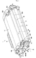
Fig. 1 is a perspective view of a developing cartridge according to one embodiment of the present invention. - [
Fig. 2 ]
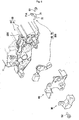
Fig. 2 is an exploded perspective view illustrating a developing electrode, a supply electrode, and other components. - [
Fig. 3 ]
Fig. 3 is a cross-sectional view illustrating a spring, a casing, a support member, and a blade. - [
Fig. 4 ]
Fig. 4 is a view illustrating a relationship between a contact portion of the spring and the blade. - [
Fig. 5 ]
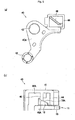
Fig. 5A is a view illustrating an electrode member as viewed from the casing.Fig. 5B is a view illustrating a relationship between a cam surface of the casing and a cam surface of the electrode member. - [
Fig. 6 ]
Fig. 6 is an exploded perspective view illustrating a supply electrode according to one modification. - [
Fig. 7 ]
Fig. 7 is a perspective view illustrating a state where the supply electrode according to the modification is assembled to the casing. - An embodiment of the present invention will next be described in detail while referring to the accompanying drawings.
- As illustrated in
Fig. 1 , a developingcartridge 1 includes acasing 11, a developingroller 12, a supply roller 13 (seeFig. 2 ), ahandgrip 14, a layerthickness regulation blade 20, a developingelectrode 30, asupply electrode 100, and abearing 60. Thesupply electrode 100 is a member electrically connected to thesupply roller 13 and the layerthickness regulation blade 20. Thesupply electrode 100 includes anelectrode member 40 and aspring 50. - The
casing 11 accommodates therein toner. Thecasing 11 is made of non-conductive resin. Thecasing 11 includes aside wall 15. Theside wall 15 is positioned at one end of the developingroller 12. - The developing
roller 12 is a roller configured to supply toner to an electrostatic latent image formed on a photosensitive body (not illustrated). The developingroller 12 is rotatable about a first axis X1 extending in an axial direction. The developingroller 12 includes ashaft 12A (seeFig. 2 ) extending in the axial direction. The developingroller 12 is positioned at oneend 11A of thecasing 11. - As illustrated in
Fig. 2 , thesupply roller 13 is a roller configured to supply toner to the developingroller 12. Thesupply roller 13 is rotatable about a second axis X2 extending in the axial direction. Thesupply roller 13 includes ashaft 13A extending in the axial direction. Thesupply roller 13 is in contact with the developingroller 12. - Turning back to
Fig. 1 , thehandgrip 14 is a portion configured to be gripped by a user. Thehandgrip 14 is positioned at theother end 11B of thecasing 11. - The layer
thickness regulation blade 20 is a member configured to regulate a thickness of a toner layer formed on the developingroller 12. The layerthickness regulation blade 20 includes ablade 21 and asupport member 22 supporting theblade 21. - The
blade 21 is a rectangular metal plate extending in the axial direction. Theblade 21 is made of metal such as stainless steel. Theblade 21 has a thickness smaller than that of the support member. One end of theblade 21 in the short direction thereof is fixed to thesupport member 22 by welding, etc. The other end of theblade 21 in the short direction thereof is in contact with a circumferential surface of the developingroller 12. - Incidentally, a rubber member may be provided at the other end in the short direction of the
blade 21. In this case, the rubber member of theblade 21 may be in contact with the developingroller 12. - The
support member 22 is made of metal such as an electro galvanized steel plate. Thesupport member 22 includes afirst wall 22A and asecond wall 22B. Thefirst wall 22A supports a surface of theblade 21 which is opposite to a surface of theblade 21 facing the developingroller 12. Thesecond wall 22B is positioned at one end portion of thefirst wall 22A which is farther from the developingroller 12 than the other end portion of thefirst wall 22A is from the developingroller 12. Thesecond wall 22B extends from thefirst wall 22A in a direction away from theblade 21. - The
first wall 22A includes two protrudingportions 22C. Each protrudingportion 22C protrudes further in a direction away from the developingroller 12 than thesecond wall 22B. Thesecond wall 22B is positioned between the two protrudingportions 22C in the axial direction. Each protrudingportion 22C has a through-hole 22D through which a first screw S1 (only one screw is depicted) is inserted. Each protrudingportion 22C is fastened to thecasing 11 by the corresponding first screw S1. - As illustrated in
Fig. 2 , thecasing 11 includes a fixingwall 16 to which the protrudingportion 22C is fixed. Theside wall 15 has anopening 15A extending therethrough in the leftward/rightward direction. Theopening 15A is overlapped with the fixingwall 16 and the protrudingportion 22C as viewed in the axial direction. A part of theopening 15A is positioned closer to the oneend 11A of thecasing 11 than the protrudingportion 22C is to the oneend 11A. With this configuration, by inserting acontact portion 53D (described later) of thespring 50 through theopening 15A, thecontact portion 53D can be inserted toward theblade 21 further than theside wall 15. - The
casing 11 has aboss 17. Theboss 17 has a tip end to which a second screw S2 is fixed for co-fastening theelectrode member 40, thebearing 60, and the developingelectrode 30. Thecasing 11 includes a protrudingportion 18 protruding from theside wall 15 toward theelectrode member 40. The protrudingportion 18 has acam surface 18A. Thecam surface 18A is a surface for moving theelectrode member 40 in a direction perpendicular to the second axis X2. Thecam surface 18A is inclined so as to approach theside wall 15 with increasing distance from the second axis X2. - The developing
electrode 30 is a member electrically connected to theshaft 12A of the developingroller 12. The developingelectrode 30 is made of electrically conductive resin. The developingelectrode 30 includes afirst contact portion 31 and acover portion 32, and has anattachment hole 33. - The
first contact portion 31 is a surface configured to contact with a first main body side electrode in the axial direction in a state where the developingcartridge 1 is attached to a main body casing of an image forming apparatus (not illustrated). The first main body side electrode is provided at the main body casing. Thefirst contact portion 31 is perpendicular to the axial direction. Thefirst contact portion 31 is positioned at a position different from the position of theshaft 12A of the developingroller 12. - The
cover portion 32 is formed in a generally hollow cylindrical shape so as to cover a circumferential surface of theshaft 12A of the developingroller 12. The inner circumferential surface of thecover portion 32 is in contact with theshaft 12A of the developingroller 12. - The
attachment hole 33 is a hole through which the second screw S2 is inserted. Theattachment hole 33 faces theboss 17 of thecasing 11 in the axial direction. The developingelectrode 30 is fixed to theboss 17 by the second screw S2. - The
bearing 60 is made of non-conductive resin. Thebearing 60 includes abase portion 60A, afirst support portion 61, asecond support portion 62, a first protrudingportion 65, and a second protrudingportion 66, and has a through-hole 63. Thebase portion 60A is formed in a flat plate shape perpendicular to the axial direction. Thebearing 60 is positioned between the developingelectrode 30 and theelectrode member 40 in the axial direction. - The
first support portion 61 is formed in a hollow cylindrical shape protruding from thebase portion 60A toward thecasing 11. The inner circumferential surface of thefirst support portion 61 supports theshaft 12A of the developingroller 12. - The
second support portion 62 includes: a hollow cylindrical portion protruding from thebase portion 60A in a direction away from thecasing 11; and a bottom portion closing the opening of the tip end of the hollow cylindrical portion. The inner circumferential surface of thesecond support portion 62 supports theshaft 13A of thesupply roller 13. - The through-
hole 63 is a circular through-hole through which theboss 17 of thecasing 11 is inserted. The through-hole 63 is positioned at a position facing theboss 17 in the axial direction. - The first protruding
portion 65 and the second protrudingportion 66 protrude from thebase portion 60A in a direction away from thecasing 11. The first protrudingportion 65 is positioned adjacent to afirst side 41A of a second contact portion 41 (described later) of theelectrode member 40. The second protrudingportion 66 is positioned adjacent to asecond side 41B of thesecond contact portion 41, thesecond side 41B being perpendicular to thefirst side 41A. - The
electrode member 40 is a member electrically connected to theshaft 13A that is a rotation shaft of thesupply roller 13. Theelectrode member 40 is made of electrically conductive resin. Theelectrode member 40 includes abase 40A, afirst portion 42, and asecond portion 44. Theelectrode member 40 is movable in a direction perpendicular to theshaft 13A of thesupply roller 13. - The
base 40A is formed in a flat plate shape perpendicular to the axial direction. Thebase 40A has ahole 43. Thebase 40A connects thefirst portion 42 and thesecond portion 44. Thebase 40A is positioned between the bearing 60 and thecasing 11 in the axial direction. - The
hole 43 is a hole for fixing theelectrode member 40 to thecasing 11. Theboss 17 of thecasing 11 is inserted through thehole 43. The diameter of thehole 43 is greater than the outer diameter of theboss 17. Arib 45 protruding from thebase 40A in a direction away from thecasing 11 is formed at the periphery of thehole 43. Therib 45 is formed in a generally arcuate shape as viewed in the axial direction. - The
first portion 42 is formed in a hollow cylindrical shape protruding from thebase 40A toward thecasing 11. The inner circumferential surface of thefirst portion 42 is in contact with theshaft 13A of thesupply roller 13. - The
second portion 44 is positioned at a position different from the position of thefirst portion 42. Thesecond portion 44 protrudes from thebase 40A in a direction away from thecasing 11. The end surface of thesecond portion 44 serves as thesecond contact portion 41. Thesecond contact portion 41 is a surface configured to contact with a second main body side electrode in the axial direction in a state where the developingcartridge 1 is attached to the main body casing of the image forming apparatus (not illustrated). The second main body side electrode is provided at the main body casing. That is, thesecond portion 44 is in contact with the second main body side electrode that is an external electrode. - The
second contact portion 41 has a rectangular shape as viewed in the axial direction. Thesecond contact portion 41 is perpendicular to the axial direction. Thesecond contact portion 41 is positioned at a position different from the position of theshaft 13A of thesupply roller 13. Specifically, thesecond contact portion 41 is positioned at a position opposite to thefirst portion 42 with respect to thehole 43. - The
electrode member 40 is connected to theblade 21 through thespring 50. That is, theelectrode member 40 is electrically connected to theblade 21 through a member other than thesupport member 22. Theelectrode member 40 is movable relative to thespring 50 in a direction perpendicular to theshaft 13A of thesupply roller 13 in a state where theelectrode member 40 is in contact with thespring 50. - The
spring 50 is a member for electrically connecting thebase 40A of theelectrode member 40 and theblade 21. Thespring 50 is made of metal. Thespring 50 includes acoil portion 51, anarm portion 52 and a nippingportion 53. As illustrated inFig. 3 , thecoil portion 51 extends in the axial direction of thesupply roller 13. Thecoil portion 51 is positioned between thebase 40A and thecasing 11. That is, thespring 50 is positioned between thebase 40A and thecasing 11. Thecoil portion 51 is in contact with thebase 40A and thecasing 11. Thecoil portion 51 is compressed from its natural length in a state where theelectrode member 40 is assembled to thecasing 11. - In the state where the
electrode member 40 is assembled to thecasing 11, theboss 17 is inserted in thecoil portion 51. Hence, thecoil portion 51 is supported by the outer circumferential surface of theboss 17. - Turning back to
Fig. 2 , thearm portion 52 is formed in a line shape. Thearm portion 52 extends toward theblade 21 from one end portion of thecoil portion 51 which is closer to thecasing 11 than the other end portion of thecoil portion 51 is to thecasing 11. Specifically, thearm portion 52 extends outward in the radial direction of thecoil portion 51 from the one end portion of thecoil portion 51. More specifically, thearm portion 52 extends from thecoil portion 51 toward the oneend 11A of thecasing 11. Thearm portion 52 includes the nippingportion 53. The nippingportion 53 nips and supports theblade 21 and the fixingwall 16 which is a part of thecasing 11. The nippingportion 53 is provided at a distal end of thearm portion 52. - As illustrated in
Fig. 3 , the nippingportion 53 nips the fixingwall 16, thesupport member 22, and theblade 21 together to support them. The nippingportion 53 has a U-shape as viewed in a direction which is perpendicular to both the axial direction and a direction perpendicular to a surface of theblade 21. Here, this surface of theblade 21 is the opposite surface to the surface of theblade 21 facing thesupport member 22. - The nipping
portion 53 mainly includes afirst part 53A, asecond part 53B, athird part 53C, and thecontact portion 53D. Thefirst part 53A extends in the axial direction. Thefirst part 53A is in contact with the fixingwall 16. - The
second part 53B extend toward the oneend 11A (seeFig. 2 ) of thecasing 11 from one end portion of thefirst part 53A which is farther from thecasing 11 than the other end portion of thefirst part 53A is from thecasing 11. Thesecond part 53B is positioned spaced away from the fixingwall 16, thesupport member 22 and theblade 21 in the axial direction. - The
third part 53C extends toward theblade 21 from one end portion of thesecond part 53B which is farther from thefirst part 53A than the other end portion of thesecond part 53B is from thefirst part 53A. Thethird part 53C is inclined with respect to the surface of theblade 21. Specifically, thethird part 53C is inclined so as to approach thefirst part 53A with decreasing distance in the axial direction between thethird part 53C and theblade 21. - The
contact portion 53D is a portion which is in contact with the surface of theblade 21. Thecontact portion 53D is provided at one end portion of thethird part 53C which is closer to theblade 21 than the other end portion of thethird part 53C is to theblade 21. - As illustrated in
Fig. 4 , thecontact portion 53D is formed in a U-shape as viewed in a direction perpendicular to the surface of theblade 21. Specifically, thecontact portion 53D has a U-shape which opens toward theside wall 15 of thecasing 11. Thecontact portion 53D extends toward the developingroller 12 from thethird part 53C as viewed in a direction perpendicular to the surface of theblade 21. - A fourth part 54E is provided at one end portion of the
contact portion 53D which is farther from thethird part 53C than the other end portion of thecontact portion 53D is from thethird part 53C. Thefourth part 53E is inclined so as to approach thethird part 53C as thefourth part 53E advances toward theside wall 15 from thecontact portion 53D. - As illustrated in
Figs. 5A and 5B , thesecond portion 44 is formed in a box shape which opens toward thecasing 11. Thesecond portion 44 has abottom surface 44A. Thesecond portion 44 includes arib 46 protruding toward thecasing 11 from thebottom surface 44A. - The
rib 46 extends along a diagonal line of the rectangularsecond contact portion 41. Therib 46 intersects the protruding portion 18 (seeFig. 2 ) of thecasing 11 as viewed in the axial direction. Therib 46 has an end surface functioning as acam surface 46A in conformance with thecam surface 18A of the protrudingportion 18 of thecasing 11. That is, thecam surface 46A is inclined so as to approach thecasing 11 with increasing distance from the second axis X2. - Incidentally, the
electrode member 40 is urged toward the bearing 60 by thespring 50. Thus, the surface of theelectrode member 40 which faces thecasing 11 is spaced away from theside wall 15. - Next, functions and effects of each member in accordance with attachment of the developing
cartridge 1 to the main body casing will be described.
As a result of attachment of the developingcartridge 1 illustrated inFig. 1 to the main body casing, the first main body side electrode is brought into contact with thefirst contact portion 31 of the developingelectrode 30 in the axial direction, and the second main body side electrode is brought into contact with thesecond contact portion 41 of theelectrode member 40 in the axial direction. Here, each of the first main body side electrode and the second main body side electrode has a spring. Hence, the second main body side electrode urges theelectrode member 40 toward thecasing 11. - As a result of the
electrode member 40 being urged toward the developingcartridge 1, thecam surface 46A of therib 46 is pressed against thecam surface 18A of thecasing 11 as illustrated inFig. 5B . Hence, as illustrated inFig. 3 , theelectrode member 40 is pressed in a direction away from the second axis X2 by thecam surface 18A of thecasing 11. Thus, thefirst portion 42 of theelectrode member 40 can be caused to satisfactorily contact with theshaft 13A of thesupply roller 13. - When performing printing control, a control device provided in the main body casing supplies electric power to the developing
roller 12, thesupply roller 13, and theblade 21. Specifically, the control device supplies electric power to theshaft 12A of the developingroller 12 through the developingelectrode 30. Moreover, the control device supplies electric power to theshaft 13A of thesupply roller 13 through theelectrode member 40. Furthermore, the control device supplies electric power to theblade 21 through both theelectrode member 40 and thespring 50. - According to the present embodiment, the following effects can be obtained in addition to the above-described effects.
Since thesupply electrode 100 is connected to theblade 21 without intervention of thesupport member 22, electric power can be satisfactorily supplied to theblade 21 in comparison with a connection configuration with intervention of thesupport member 22 whose electrical conductivity has been lowered due to surface treatment. - Since the
spring 50 is interposed between the base 40A of theelectrode member 40 and thecasing 11, a good contact state between thespring 50 and thebase 40A can be maintained. - The position of the
spring 50 can be favorably fixed relative to thecasing 11 since thecoil portion 51 of thespring 50 is supported by the outer circumferential surface of theboss 17. - Because the fixing
wall 16 and theblade 21 are nipped by the nippingportion 53 of thespring 50, a good contact state between thespring 50 and theblade 21 can be maintained. - Note that the present invention is not limited to the above-described embodiment and various embodiments are conceivable. In the following description, like parts and components are designated by the same reference numerals as those shown in the above-described embodiment to avoid duplicating description.
- In the above-described embodiment, the
electrode member 40 is connected to theblade 21 through thespring 50. However, the present invention is not limited to this structure. For example, as illustrated inFig. 6 , theelectrode member 40 may be connected to theblade 21 through aconnection member 70 made of electrically conductive resin or metal. - Specifically, according to this embodiment, a
supply electrode 200 includes theelectrode member 40 of the above-described embodiment and theconnection member 70. Theconnection member 70 includes aplate portion 71 and anextension portion 72. Theplate portion 71 faces the protrudingportion 22C of thesupport member 22 and theblade 21. Theplate portion 71 has ahole 71A through which the first screw S1 is inserted. As illustrated inFig. 7 , theplate portion 71 is fixed to thecasing 11 together with the protrudingportion 22C of thesupport member 22 by the first screw S1. Theplate portion 71 is in contact with theblade 21. - The
extension portion 72 extends from theplate portion 71 toward therib 45 of theelectrode member 40. Specifically, theextension portion 72 extends in a direction perpendicular to theplate portion 71. The tip end portion of theextension portion 72 is in contact with therib 45. Also in this embodiment, since thesupply electrode 200 is connected to theblade 21 without intervention of thesupport member 22, electric power can be satisfactorily supplied to theblade 21 in comparison with a connection configuration with intervention of thesupport member 22 whose electrical conductivity has been lowered due to surface treatment. Furthermore, in this embodiment, since theconnection member 70 and thesupport member 22 are co-fastened to thecasing 11, theconnection member 70 can be caused to satisfactorily contact with theblade 21 by the fastening force of the co-fastening. - In the above-described embodiments, the connection member (50 or 70) is formed separately from the
electrode member 40. However, the present invention is not limited to this structure and the connection member may be formed integrally with the electrode member. For example, theconnection member 70 illustrated inFig. 7 may be formed integrally with theelectrode member 40. - Incidentally, the materials of the developing
electrode 30,electrode member 40 and thespring 50 can be changed as appropriate. For example, the developingelectrode 30 and theelectrode member 40 may be made of any other electrically conductive material such as metal. Moreover, thespring 50 may be made of any other electrically conductive material such as electrically conductive resin. - In the above-described embodiment, the
spring 50 including thecoil portion 51 has been described as an example of the spring. However, the present invention is not limited to this structure. For example, a leaf spring may be used as the spring. - Further, the present invention may be implemented with any combination of the components employed in the above-described embodiments and modifications.
-
- 1: developing cartridge
- 11: casing
- 12: developing roller
- 13: supply roller
- 20: layer thickness regulation blade
- 21: blade
- 22: support member
- 30: developing electrode
- 40A: base
- 50: spring
- 100: supply electrode
Claims (15)
- A developing cartridge comprising:a casing configured to accommodate therein toner;a developing roller;a supply roller configured to supply the toner to the developing roller;a layer thickness regulation blade in contact with a circumferential surface of the developing roller;a developing electrode electrically connected to the developing roller; anda supply electrode electrically connected to the supply roller and the layer thickness regulation blade, the supply electrode comprising:an electrode member electrically connected to a rotation shaft of the supply roller, the electrode member being movable in a direction perpendicular to the rotation shaft of the supply roller; anda connection member electrically connecting the electrode member and the layer thickness regulation blade, the connection member being in contact with the electrode member and the layer thickness regulation blade,wherein the electrode member is movable relative to the connection member in the direction perpendicular to the rotation shaft of the supply roller in a state where the electrode member is in contact with the connection member.
- The developing cartridge according to claim 1, wherein the connection member is a spring.
- The developing cartridge according to claim 2, wherein the spring comprises:a coil portion extending in an axial direction of the supply roller; andan arm portion having a line shape extending from the coil portion toward the layer thickness regulation blade, the arm portion being in contact with the layer thickness regulation blade.
- The developing cartridge according to claim 3, wherein the electrode member comprises a base having a hole for fixing the electrode member to the casing, and
wherein the coil portion is positioned between the base and the casing and is in contact with the base. - The developing cartridge according to claim 4, wherein the casing comprises a boss to which a screw is fixed, the boss being inserted through the hole of the base, and
wherein the coil portion is supported by the boss. - The developing cartridge according to claim 5, wherein the developing electrode is fixed to the boss by the screw.
- The developing cartridge according to any one of claims 3 to 6, wherein the arm portion comprises a nipping portion nipping a part of the casing and the layer thickness regulation blade.
- The developing cartridge according to any one of claims 3 to 7, wherein the layer thickness regulation blade comprises:a blade in contact with the circumferential surface of the developing roller; anda support member supporting the blade, andwherein the arm portion is in contact with the blade.
- The developing cartridge according to claim 4, wherein the spring is positioned between the casing and the base.
- The developing cartridge according to claim 4, wherein the electrode member comprises:a first portion in contact with the supply roller; anda second portion positioned at a position different from a position of the first portion, the second portion being capable of contacting with an external electrode, andwherein the base connects the first portion and the second portion.
- The developing cartridge according to claim 8, wherein the connection member comprises a plate portion fixed to the casing together with the support portion by a screw.
- The developing cartridge according to claim 11, wherein the connection member is made of electrically conductive resin.
- The developing cartridge according to claim 11, wherein the connection member is made of metal.
- The developing cartridge according to any one of claims 1 to 13, wherein the casing has a cam surface for moving the supply electrode in a direction perpendicular to the rotation shaft of the supply roller.
- The developing cartridge according to claim 8, wherein the support member has a through-hole through which a screw is inserted.
Applications Claiming Priority (2)
| Application Number | Priority Date | Filing Date | Title |
|---|---|---|---|
| JP2017015177A JP6733567B2 (en) | 2017-01-31 | 2017-01-31 | Developer cartridge |
| PCT/JP2017/023027 WO2018142641A1 (en) | 2017-01-31 | 2017-06-22 | Developer cartridge |
Publications (3)
| Publication Number | Publication Date |
|---|---|
| EP3579054A1 true EP3579054A1 (en) | 2019-12-11 |
| EP3579054A4 EP3579054A4 (en) | 2020-11-04 |
| EP3579054B1 EP3579054B1 (en) | 2022-09-07 |
Family
ID=63039531
Family Applications (1)
| Application Number | Title | Priority Date | Filing Date |
|---|---|---|---|
| EP17894728.9A Active EP3579054B1 (en) | 2017-01-31 | 2017-06-22 | Developing cartridge |
Country Status (5)
| Country | Link |
|---|---|
| US (5) | US10649366B2 (en) |
| EP (1) | EP3579054B1 (en) |
| JP (1) | JP6733567B2 (en) |
| CN (1) | CN110235063B (en) |
| WO (1) | WO2018142641A1 (en) |
Families Citing this family (4)
| Publication number | Priority date | Publication date | Assignee | Title |
|---|---|---|---|---|
| JP7666017B2 (en) * | 2021-02-25 | 2025-04-22 | ブラザー工業株式会社 | Developing cartridge |
| WO2024024439A1 (en) | 2022-07-28 | 2024-02-01 | キヤノン株式会社 | Cartridge |
| US12197145B1 (en) | 2023-04-27 | 2025-01-14 | Jiangxi Yibo E-Tech Co. Ltd. | Developing cartridge |
| CN117492342B (en) * | 2023-12-12 | 2024-04-30 | 珠海市颂洋科技有限公司 | Developing cartridge |
Family Cites Families (36)
| Publication number | Priority date | Publication date | Assignee | Title |
|---|---|---|---|---|
| JPH06313996A (en) * | 1993-04-28 | 1994-11-08 | Canon Inc | Process cartridge, image forming device, method for assembling process cartridge and developing device |
| JP3256394B2 (en) * | 1994-12-14 | 2002-02-12 | シャープ株式会社 | Image forming device |
| JPH08188297A (en) * | 1995-01-10 | 1996-07-23 | Canon Inc | Sheet thickness detector |
| JP3658202B2 (en) * | 1998-08-31 | 2005-06-08 | キヤノン株式会社 | Developing cartridge assembly method |
| JP2000132062A (en) * | 1998-10-26 | 2000-05-12 | Canon Inc | Process cartridge and electrophotographic image forming apparatus |
| JP3890152B2 (en) * | 1998-10-28 | 2007-03-07 | キヤノン株式会社 | Electrophotographic image forming apparatus |
| JP2001228706A (en) * | 2000-02-18 | 2001-08-24 | Ricoh Co Ltd | Developing device |
| JP4677093B2 (en) * | 2000-12-25 | 2011-04-27 | キヤノン株式会社 | Process cartridge |
| JP3840063B2 (en) * | 2001-04-27 | 2006-11-01 | キヤノン株式会社 | Process cartridge |
| JP3542588B2 (en) * | 2002-09-30 | 2004-07-14 | キヤノン株式会社 | Developing cartridge, mounting method of one end side cover, mounting method of other end side cover, and electrophotographic image forming apparatus |
| JP2004191526A (en) * | 2002-12-10 | 2004-07-08 | Seiko Epson Corp | Apparatus for urging electric contact to rotating shaft and developing cartridge provided with the same |
| US7155151B2 (en) | 2002-11-20 | 2006-12-26 | Seiko Epson Corporation | Developer carrier, developing device, image forming apparatus and computer system |
| JP2005041610A (en) | 2003-07-24 | 2005-02-17 | Kyocera Mita Corp | Grounding mechanism and image forming device using the same |
| JP3948443B2 (en) * | 2003-08-25 | 2007-07-25 | 村田機械株式会社 | Developer and image forming apparatus having the same |
| JP4716013B2 (en) * | 2005-10-24 | 2011-07-06 | セイコーエプソン株式会社 | Development device |
| JP4760395B2 (en) | 2006-01-19 | 2011-08-31 | ブラザー工業株式会社 | Cartridge and image forming apparatus |
| JP4808060B2 (en) * | 2006-03-27 | 2011-11-02 | 京セラミタ株式会社 | Developing device and image forming apparatus having the same |
| JP5162140B2 (en) * | 2007-02-15 | 2013-03-13 | 京セラドキュメントソリューションズ株式会社 | Developing device in image forming apparatus |
| JP4544307B2 (en) * | 2008-01-10 | 2010-09-15 | セイコーエプソン株式会社 | Image forming apparatus and image forming method |
| JP2010072458A (en) * | 2008-09-19 | 2010-04-02 | Fuji Xerox Co Ltd | Blade support, photoreceptor unit and image forming apparatus |
| JP2010079212A (en) | 2008-09-29 | 2010-04-08 | Canon Inc | Image forming apparatus |
| CN101477324A (en) * | 2009-01-09 | 2009-07-08 | 珠海赛纳科技有限公司 | Residual powder cleaning equipment |
| CN201583792U (en) * | 2009-12-08 | 2010-09-15 | 珠海天威飞马打印耗材有限公司 | Developing agent box |
| JP4775504B2 (en) * | 2010-11-25 | 2011-09-21 | ブラザー工業株式会社 | Cartridge and image forming apparatus |
| JP6035920B2 (en) * | 2012-07-09 | 2016-11-30 | ブラザー工業株式会社 | Developer cartridge |
| JP5962271B2 (en) * | 2012-07-09 | 2016-08-03 | ブラザー工業株式会社 | Developer cartridge |
| JP6056406B2 (en) * | 2012-11-20 | 2017-01-11 | ブラザー工業株式会社 | Cartridge and cartridge manufacturing method |
| JP2014109648A (en) * | 2012-11-30 | 2014-06-12 | Brother Ind Ltd | Development apparatus |
| JP6136603B2 (en) * | 2013-06-07 | 2017-05-31 | ブラザー工業株式会社 | cartridge |
| CN203490467U (en) * | 2013-10-10 | 2014-03-19 | 珠海赛纳打印科技股份有限公司 | Processing box and image forming equipment |
| JP6237239B2 (en) | 2014-01-06 | 2017-11-29 | ブラザー工業株式会社 | Developer cartridge |
| JP2015129814A (en) * | 2014-01-06 | 2015-07-16 | ブラザー工業株式会社 | Process cartridge and photoreceptor cartridge |
| US9507315B2 (en) | 2014-01-06 | 2016-11-29 | Brother Kogyo Kabushiki Kaisha | Developing cartridge provided with supply electrode and protecting portion capable of protecting supply electrode |
| US20160077485A1 (en) * | 2014-09-17 | 2016-03-17 | Lexmark International, Inc. | Manually Removable Separator for Neutralizing Static Charge Buildup on a Replaceable Unit of an Electrophotographic Image Forming Device |
| JP6444167B2 (en) | 2014-12-25 | 2018-12-26 | キヤノン株式会社 | Unit and cartridge |
| JP6287899B2 (en) | 2015-03-10 | 2018-03-07 | 京セラドキュメントソリューションズ株式会社 | Image forming apparatus |
-
2017
- 2017-01-31 JP JP2017015177A patent/JP6733567B2/en active Active
- 2017-06-22 CN CN201780085204.1A patent/CN110235063B/en active Active
- 2017-06-22 EP EP17894728.9A patent/EP3579054B1/en active Active
- 2017-06-22 WO PCT/JP2017/023027 patent/WO2018142641A1/en not_active Ceased
-
2019
- 2019-07-30 US US16/525,877 patent/US10649366B2/en active Active
-
2020
- 2020-04-09 US US16/843,926 patent/US11073785B2/en active Active
-
2021
- 2021-07-14 US US17/375,187 patent/US11733643B2/en active Active
-
2023
- 2023-06-29 US US18/343,856 patent/US12204274B2/en active Active
-
2024
- 2024-12-10 US US18/975,480 patent/US20250102997A1/en active Pending
Also Published As
| Publication number | Publication date |
|---|---|
| EP3579054A4 (en) | 2020-11-04 |
| WO2018142641A1 (en) | 2018-08-09 |
| US12204274B2 (en) | 2025-01-21 |
| US10649366B2 (en) | 2020-05-12 |
| JP2018124368A (en) | 2018-08-09 |
| JP6733567B2 (en) | 2020-08-05 |
| US20250102997A1 (en) | 2025-03-27 |
| CN110235063A (en) | 2019-09-13 |
| US20200233335A1 (en) | 2020-07-23 |
| US20230341810A1 (en) | 2023-10-26 |
| EP3579054B1 (en) | 2022-09-07 |
| CN110235063B (en) | 2022-04-08 |
| US20190354037A1 (en) | 2019-11-21 |
| US11733643B2 (en) | 2023-08-22 |
| US11073785B2 (en) | 2021-07-27 |
| US20210382433A1 (en) | 2021-12-09 |
Similar Documents
| Publication | Publication Date | Title |
|---|---|---|
| US12204274B2 (en) | Developing cartridge including supply roller, layer thickness regulation blade, and supply electrode electrically connected to both supply roller and layer thickness regulation blade | |
| US10126704B2 (en) | Drum cartridge and developing cartridge capable of suppressing variation in position of electrical contact surface | |
| JP7306009B2 (en) | developer cartridge | |
| US9915917B2 (en) | Process cartridge capable of restraining frictional wearing of electrode provided at developing unit | |
| CN203490467U (en) | Processing box and image forming equipment | |
| JP2023166592A5 (en) | ||
| JP2001201996A (en) | Image forming apparatus and process cartridge | |
| JP5162140B2 (en) | Developing device in image forming apparatus | |
| EP3779601A1 (en) | Developing cartridge | |
| JP6930072B2 (en) | Development cartridge | |
| US8254816B2 (en) | Developing device | |
| JP7004035B2 (en) | Develop cartridge | |
| JP6520473B2 (en) | Power supply structure, charging device, assembly and image forming apparatus | |
| JP2019040157A (en) | Image holding body, image forming unit, and image forming apparatus | |
| CN216792682U (en) | Developing box | |
| US9785092B1 (en) | Developing cartridge provided with developing roller, gear cover, and electric contact | |
| JPH10333493A (en) | Cylindrical member and its fixing method | |
| JP2007133180A (en) | Developing device and developing roller | |
| JPH10319784A (en) | Drum unit and earth plate used for drum unit | |
| JP2000315011A5 (en) | ||
| JP2005189265A (en) | Corona charger |
Legal Events
| Date | Code | Title | Description |
|---|---|---|---|
| STAA | Information on the status of an ep patent application or granted ep patent |
Free format text: STATUS: THE INTERNATIONAL PUBLICATION HAS BEEN MADE |
|
| PUAI | Public reference made under article 153(3) epc to a published international application that has entered the european phase |
Free format text: ORIGINAL CODE: 0009012 |
|
| STAA | Information on the status of an ep patent application or granted ep patent |
Free format text: STATUS: REQUEST FOR EXAMINATION WAS MADE |
|
| 17P | Request for examination filed |
Effective date: 20190731 |
|
| AK | Designated contracting states |
Kind code of ref document: A1 Designated state(s): AL AT BE BG CH CY CZ DE DK EE ES FI FR GB GR HR HU IE IS IT LI LT LU LV MC MK MT NL NO PL PT RO RS SE SI SK SM TR |
|
| AX | Request for extension of the european patent |
Extension state: BA ME |
|
| DAV | Request for validation of the european patent (deleted) | ||
| DAX | Request for extension of the european patent (deleted) | ||
| A4 | Supplementary search report drawn up and despatched |
Effective date: 20201001 |
|
| RIC1 | Information provided on ipc code assigned before grant |
Ipc: G03G 21/16 20060101ALI20200925BHEP Ipc: G03G 15/08 20060101AFI20200925BHEP |
|
| GRAP | Despatch of communication of intention to grant a patent |
Free format text: ORIGINAL CODE: EPIDOSNIGR1 |
|
| STAA | Information on the status of an ep patent application or granted ep patent |
Free format text: STATUS: GRANT OF PATENT IS INTENDED |
|
| INTG | Intention to grant announced |
Effective date: 20220413 |
|
| GRAS | Grant fee paid |
Free format text: ORIGINAL CODE: EPIDOSNIGR3 |
|
| GRAA | (expected) grant |
Free format text: ORIGINAL CODE: 0009210 |
|
| STAA | Information on the status of an ep patent application or granted ep patent |
Free format text: STATUS: THE PATENT HAS BEEN GRANTED |
|
| AK | Designated contracting states |
Kind code of ref document: B1 Designated state(s): AL AT BE BG CH CY CZ DE DK EE ES FI FR GB GR HR HU IE IS IT LI LT LU LV MC MK MT NL NO PL PT RO RS SE SI SK SM TR |
|
| REG | Reference to a national code |
Ref country code: GB Ref legal event code: FG4D |
|
| REG | Reference to a national code |
Ref country code: CH Ref legal event code: EP Ref country code: AT Ref legal event code: REF Ref document number: 1517558 Country of ref document: AT Kind code of ref document: T Effective date: 20220915 |
|
| REG | Reference to a national code |
Ref country code: DE Ref legal event code: R096 Ref document number: 602017061673 Country of ref document: DE |
|
| REG | Reference to a national code |
Ref country code: IE Ref legal event code: FG4D |
|
| REG | Reference to a national code |
Ref country code: LT Ref legal event code: MG9D |
|
| REG | Reference to a national code |
Ref country code: NL Ref legal event code: MP Effective date: 20220907 |
|
| PG25 | Lapsed in a contracting state [announced via postgrant information from national office to epo] |
Ref country code: SE Free format text: LAPSE BECAUSE OF FAILURE TO SUBMIT A TRANSLATION OF THE DESCRIPTION OR TO PAY THE FEE WITHIN THE PRESCRIBED TIME-LIMIT Effective date: 20220907 Ref country code: RS Free format text: LAPSE BECAUSE OF FAILURE TO SUBMIT A TRANSLATION OF THE DESCRIPTION OR TO PAY THE FEE WITHIN THE PRESCRIBED TIME-LIMIT Effective date: 20220907 Ref country code: NO Free format text: LAPSE BECAUSE OF FAILURE TO SUBMIT A TRANSLATION OF THE DESCRIPTION OR TO PAY THE FEE WITHIN THE PRESCRIBED TIME-LIMIT Effective date: 20221207 Ref country code: LV Free format text: LAPSE BECAUSE OF FAILURE TO SUBMIT A TRANSLATION OF THE DESCRIPTION OR TO PAY THE FEE WITHIN THE PRESCRIBED TIME-LIMIT Effective date: 20220907 Ref country code: LT Free format text: LAPSE BECAUSE OF FAILURE TO SUBMIT A TRANSLATION OF THE DESCRIPTION OR TO PAY THE FEE WITHIN THE PRESCRIBED TIME-LIMIT Effective date: 20220907 Ref country code: FI Free format text: LAPSE BECAUSE OF FAILURE TO SUBMIT A TRANSLATION OF THE DESCRIPTION OR TO PAY THE FEE WITHIN THE PRESCRIBED TIME-LIMIT Effective date: 20220907 |
|
| REG | Reference to a national code |
Ref country code: AT Ref legal event code: MK05 Ref document number: 1517558 Country of ref document: AT Kind code of ref document: T Effective date: 20220907 |
|
| PG25 | Lapsed in a contracting state [announced via postgrant information from national office to epo] |
Ref country code: HR Free format text: LAPSE BECAUSE OF FAILURE TO SUBMIT A TRANSLATION OF THE DESCRIPTION OR TO PAY THE FEE WITHIN THE PRESCRIBED TIME-LIMIT Effective date: 20220907 Ref country code: GR Free format text: LAPSE BECAUSE OF FAILURE TO SUBMIT A TRANSLATION OF THE DESCRIPTION OR TO PAY THE FEE WITHIN THE PRESCRIBED TIME-LIMIT Effective date: 20221208 |
|
| PG25 | Lapsed in a contracting state [announced via postgrant information from national office to epo] |
Ref country code: SM Free format text: LAPSE BECAUSE OF FAILURE TO SUBMIT A TRANSLATION OF THE DESCRIPTION OR TO PAY THE FEE WITHIN THE PRESCRIBED TIME-LIMIT Effective date: 20220907 Ref country code: RO Free format text: LAPSE BECAUSE OF FAILURE TO SUBMIT A TRANSLATION OF THE DESCRIPTION OR TO PAY THE FEE WITHIN THE PRESCRIBED TIME-LIMIT Effective date: 20220907 Ref country code: PT Free format text: LAPSE BECAUSE OF FAILURE TO SUBMIT A TRANSLATION OF THE DESCRIPTION OR TO PAY THE FEE WITHIN THE PRESCRIBED TIME-LIMIT Effective date: 20230109 Ref country code: ES Free format text: LAPSE BECAUSE OF FAILURE TO SUBMIT A TRANSLATION OF THE DESCRIPTION OR TO PAY THE FEE WITHIN THE PRESCRIBED TIME-LIMIT Effective date: 20220907 Ref country code: CZ Free format text: LAPSE BECAUSE OF FAILURE TO SUBMIT A TRANSLATION OF THE DESCRIPTION OR TO PAY THE FEE WITHIN THE PRESCRIBED TIME-LIMIT Effective date: 20220907 Ref country code: AT Free format text: LAPSE BECAUSE OF FAILURE TO SUBMIT A TRANSLATION OF THE DESCRIPTION OR TO PAY THE FEE WITHIN THE PRESCRIBED TIME-LIMIT Effective date: 20220907 |
|
| PG25 | Lapsed in a contracting state [announced via postgrant information from national office to epo] |
Ref country code: SK Free format text: LAPSE BECAUSE OF FAILURE TO SUBMIT A TRANSLATION OF THE DESCRIPTION OR TO PAY THE FEE WITHIN THE PRESCRIBED TIME-LIMIT Effective date: 20220907 Ref country code: PL Free format text: LAPSE BECAUSE OF FAILURE TO SUBMIT A TRANSLATION OF THE DESCRIPTION OR TO PAY THE FEE WITHIN THE PRESCRIBED TIME-LIMIT Effective date: 20220907 Ref country code: IS Free format text: LAPSE BECAUSE OF FAILURE TO SUBMIT A TRANSLATION OF THE DESCRIPTION OR TO PAY THE FEE WITHIN THE PRESCRIBED TIME-LIMIT Effective date: 20230107 Ref country code: EE Free format text: LAPSE BECAUSE OF FAILURE TO SUBMIT A TRANSLATION OF THE DESCRIPTION OR TO PAY THE FEE WITHIN THE PRESCRIBED TIME-LIMIT Effective date: 20220907 |
|
| REG | Reference to a national code |
Ref country code: DE Ref legal event code: R097 Ref document number: 602017061673 Country of ref document: DE |
|
| P01 | Opt-out of the competence of the unified patent court (upc) registered |
Effective date: 20230523 |
|
| PG25 | Lapsed in a contracting state [announced via postgrant information from national office to epo] |
Ref country code: NL Free format text: LAPSE BECAUSE OF FAILURE TO SUBMIT A TRANSLATION OF THE DESCRIPTION OR TO PAY THE FEE WITHIN THE PRESCRIBED TIME-LIMIT Effective date: 20220907 Ref country code: AL Free format text: LAPSE BECAUSE OF FAILURE TO SUBMIT A TRANSLATION OF THE DESCRIPTION OR TO PAY THE FEE WITHIN THE PRESCRIBED TIME-LIMIT Effective date: 20220907 |
|
| PLBE | No opposition filed within time limit |
Free format text: ORIGINAL CODE: 0009261 |
|
| STAA | Information on the status of an ep patent application or granted ep patent |
Free format text: STATUS: NO OPPOSITION FILED WITHIN TIME LIMIT |
|
| PG25 | Lapsed in a contracting state [announced via postgrant information from national office to epo] |
Ref country code: DK Free format text: LAPSE BECAUSE OF FAILURE TO SUBMIT A TRANSLATION OF THE DESCRIPTION OR TO PAY THE FEE WITHIN THE PRESCRIBED TIME-LIMIT Effective date: 20220907 |
|
| 26N | No opposition filed |
Effective date: 20230608 |
|
| PG25 | Lapsed in a contracting state [announced via postgrant information from national office to epo] |
Ref country code: SI Free format text: LAPSE BECAUSE OF FAILURE TO SUBMIT A TRANSLATION OF THE DESCRIPTION OR TO PAY THE FEE WITHIN THE PRESCRIBED TIME-LIMIT Effective date: 20220907 |
|
| PG25 | Lapsed in a contracting state [announced via postgrant information from national office to epo] |
Ref country code: MC Free format text: LAPSE BECAUSE OF FAILURE TO SUBMIT A TRANSLATION OF THE DESCRIPTION OR TO PAY THE FEE WITHIN THE PRESCRIBED TIME-LIMIT Effective date: 20220907 |
|
| PG25 | Lapsed in a contracting state [announced via postgrant information from national office to epo] |
Ref country code: MC Free format text: LAPSE BECAUSE OF FAILURE TO SUBMIT A TRANSLATION OF THE DESCRIPTION OR TO PAY THE FEE WITHIN THE PRESCRIBED TIME-LIMIT Effective date: 20220907 |
|
| REG | Reference to a national code |
Ref country code: CH Ref legal event code: PL |
|
| REG | Reference to a national code |
Ref country code: BE Ref legal event code: MM Effective date: 20230630 |
|
| PG25 | Lapsed in a contracting state [announced via postgrant information from national office to epo] |
Ref country code: LU Free format text: LAPSE BECAUSE OF NON-PAYMENT OF DUE FEES Effective date: 20230622 |
|
| REG | Reference to a national code |
Ref country code: IE Ref legal event code: MM4A |
|
| PG25 | Lapsed in a contracting state [announced via postgrant information from national office to epo] |
Ref country code: LU Free format text: LAPSE BECAUSE OF NON-PAYMENT OF DUE FEES Effective date: 20230622 |
|
| PG25 | Lapsed in a contracting state [announced via postgrant information from national office to epo] |
Ref country code: IE Free format text: LAPSE BECAUSE OF NON-PAYMENT OF DUE FEES Effective date: 20230622 |
|
| PG25 | Lapsed in a contracting state [announced via postgrant information from national office to epo] |
Ref country code: IE Free format text: LAPSE BECAUSE OF NON-PAYMENT OF DUE FEES Effective date: 20230622 Ref country code: CH Free format text: LAPSE BECAUSE OF NON-PAYMENT OF DUE FEES Effective date: 20230630 |
|
| PG25 | Lapsed in a contracting state [announced via postgrant information from national office to epo] |
Ref country code: IT Free format text: LAPSE BECAUSE OF FAILURE TO SUBMIT A TRANSLATION OF THE DESCRIPTION OR TO PAY THE FEE WITHIN THE PRESCRIBED TIME-LIMIT Effective date: 20220907 Ref country code: BE Free format text: LAPSE BECAUSE OF NON-PAYMENT OF DUE FEES Effective date: 20230630 |
|
| PG25 | Lapsed in a contracting state [announced via postgrant information from national office to epo] |
Ref country code: BG Free format text: LAPSE BECAUSE OF FAILURE TO SUBMIT A TRANSLATION OF THE DESCRIPTION OR TO PAY THE FEE WITHIN THE PRESCRIBED TIME-LIMIT Effective date: 20220907 |
|
| PG25 | Lapsed in a contracting state [announced via postgrant information from national office to epo] |
Ref country code: BG Free format text: LAPSE BECAUSE OF FAILURE TO SUBMIT A TRANSLATION OF THE DESCRIPTION OR TO PAY THE FEE WITHIN THE PRESCRIBED TIME-LIMIT Effective date: 20220907 |
|
| PGFP | Annual fee paid to national office [announced via postgrant information from national office to epo] |
Ref country code: DE Payment date: 20250509 Year of fee payment: 9 |
|
| PGFP | Annual fee paid to national office [announced via postgrant information from national office to epo] |
Ref country code: GB Payment date: 20250508 Year of fee payment: 9 |
|
| PGFP | Annual fee paid to national office [announced via postgrant information from national office to epo] |
Ref country code: FR Payment date: 20250512 Year of fee payment: 9 |
|
| PG25 | Lapsed in a contracting state [announced via postgrant information from national office to epo] |
Ref country code: CY Free format text: LAPSE BECAUSE OF FAILURE TO SUBMIT A TRANSLATION OF THE DESCRIPTION OR TO PAY THE FEE WITHIN THE PRESCRIBED TIME-LIMIT; INVALID AB INITIO Effective date: 20170622 |
|
| PG25 | Lapsed in a contracting state [announced via postgrant information from national office to epo] |
Ref country code: HU Free format text: LAPSE BECAUSE OF FAILURE TO SUBMIT A TRANSLATION OF THE DESCRIPTION OR TO PAY THE FEE WITHIN THE PRESCRIBED TIME-LIMIT; INVALID AB INITIO Effective date: 20170622 |
|
| PG25 | Lapsed in a contracting state [announced via postgrant information from national office to epo] |
Ref country code: TR Free format text: LAPSE BECAUSE OF FAILURE TO SUBMIT A TRANSLATION OF THE DESCRIPTION OR TO PAY THE FEE WITHIN THE PRESCRIBED TIME-LIMIT Effective date: 20220907 |