EP3578953A1 - Apparatus for inspecting quality of porous body and method for inspecting quality of porous body - Google Patents
Apparatus for inspecting quality of porous body and method for inspecting quality of porous body Download PDFInfo
- Publication number
- EP3578953A1 EP3578953A1 EP18751648.9A EP18751648A EP3578953A1 EP 3578953 A1 EP3578953 A1 EP 3578953A1 EP 18751648 A EP18751648 A EP 18751648A EP 3578953 A1 EP3578953 A1 EP 3578953A1
- Authority
- EP
- European Patent Office
- Prior art keywords
- porous body
- pressure
- base material
- contact resistance
- diffusion layer
- Prior art date
- Legal status (The legal status is an assumption and is not a legal conclusion. Google has not performed a legal analysis and makes no representation as to the accuracy of the status listed.)
- Granted
Links
Images


Classifications
-
- H—ELECTRICITY
- H01—ELECTRIC ELEMENTS
- H01M—PROCESSES OR MEANS, e.g. BATTERIES, FOR THE DIRECT CONVERSION OF CHEMICAL ENERGY INTO ELECTRICAL ENERGY
- H01M8/00—Fuel cells; Manufacture thereof
- H01M8/04—Auxiliary arrangements, e.g. for control of pressure or for circulation of fluids
- H01M8/04298—Processes for controlling fuel cells or fuel cell systems
- H01M8/04305—Modeling, demonstration models of fuel cells, e.g. for training purposes
-
- H—ELECTRICITY
- H01—ELECTRIC ELEMENTS
- H01M—PROCESSES OR MEANS, e.g. BATTERIES, FOR THE DIRECT CONVERSION OF CHEMICAL ENERGY INTO ELECTRICAL ENERGY
- H01M10/00—Secondary cells; Manufacture thereof
- H01M10/42—Methods or arrangements for servicing or maintenance of secondary cells or secondary half-cells
- H01M10/4285—Testing apparatus
-
- G—PHYSICS
- G01—MEASURING; TESTING
- G01N—INVESTIGATING OR ANALYSING MATERIALS BY DETERMINING THEIR CHEMICAL OR PHYSICAL PROPERTIES
- G01N15/00—Investigating characteristics of particles; Investigating permeability, pore-volume or surface-area of porous materials
- G01N15/08—Investigating permeability, pore-volume, or surface area of porous materials
-
- G—PHYSICS
- G01—MEASURING; TESTING
- G01N—INVESTIGATING OR ANALYSING MATERIALS BY DETERMINING THEIR CHEMICAL OR PHYSICAL PROPERTIES
- G01N27/00—Investigating or analysing materials by the use of electric, electrochemical, or magnetic means
- G01N27/02—Investigating or analysing materials by the use of electric, electrochemical, or magnetic means by investigating impedance
- G01N27/04—Investigating or analysing materials by the use of electric, electrochemical, or magnetic means by investigating impedance by investigating resistance
-
- H—ELECTRICITY
- H01—ELECTRIC ELEMENTS
- H01M—PROCESSES OR MEANS, e.g. BATTERIES, FOR THE DIRECT CONVERSION OF CHEMICAL ENERGY INTO ELECTRICAL ENERGY
- H01M4/00—Electrodes
- H01M4/02—Electrodes composed of, or comprising, active material
- H01M4/64—Carriers or collectors
- H01M4/70—Carriers or collectors characterised by shape or form
- H01M4/80—Porous plates, e.g. sintered carriers
-
- H—ELECTRICITY
- H01—ELECTRIC ELEMENTS
- H01M—PROCESSES OR MEANS, e.g. BATTERIES, FOR THE DIRECT CONVERSION OF CHEMICAL ENERGY INTO ELECTRICAL ENERGY
- H01M4/00—Electrodes
- H01M4/86—Inert electrodes with catalytic activity, e.g. for fuel cells
- H01M4/88—Processes of manufacture
- H01M4/8803—Supports for the deposition of the catalytic active composition
- H01M4/8807—Gas diffusion layers
-
- H—ELECTRICITY
- H01—ELECTRIC ELEMENTS
- H01M—PROCESSES OR MEANS, e.g. BATTERIES, FOR THE DIRECT CONVERSION OF CHEMICAL ENERGY INTO ELECTRICAL ENERGY
- H01M8/00—Fuel cells; Manufacture thereof
- H01M8/10—Fuel cells with solid electrolytes
- H01M2008/1095—Fuel cells with polymeric electrolytes
-
- H—ELECTRICITY
- H01—ELECTRIC ELEMENTS
- H01M—PROCESSES OR MEANS, e.g. BATTERIES, FOR THE DIRECT CONVERSION OF CHEMICAL ENERGY INTO ELECTRICAL ENERGY
- H01M8/00—Fuel cells; Manufacture thereof
- H01M8/02—Details
- H01M8/0202—Collectors; Separators, e.g. bipolar separators; Interconnectors
- H01M8/0204—Non-porous and characterised by the material
- H01M8/0206—Metals or alloys
-
- H—ELECTRICITY
- H01—ELECTRIC ELEMENTS
- H01M—PROCESSES OR MEANS, e.g. BATTERIES, FOR THE DIRECT CONVERSION OF CHEMICAL ENERGY INTO ELECTRICAL ENERGY
- H01M8/00—Fuel cells; Manufacture thereof
- H01M8/02—Details
- H01M8/0202—Collectors; Separators, e.g. bipolar separators; Interconnectors
- H01M8/0204—Non-porous and characterised by the material
- H01M8/0223—Composites
- H01M8/0228—Composites in the form of layered or coated products
-
- H—ELECTRICITY
- H01—ELECTRIC ELEMENTS
- H01M—PROCESSES OR MEANS, e.g. BATTERIES, FOR THE DIRECT CONVERSION OF CHEMICAL ENERGY INTO ELECTRICAL ENERGY
- H01M8/00—Fuel cells; Manufacture thereof
- H01M8/02—Details
- H01M8/0202—Collectors; Separators, e.g. bipolar separators; Interconnectors
- H01M8/023—Porous and characterised by the material
- H01M8/0232—Metals or alloys
-
- Y—GENERAL TAGGING OF NEW TECHNOLOGICAL DEVELOPMENTS; GENERAL TAGGING OF CROSS-SECTIONAL TECHNOLOGIES SPANNING OVER SEVERAL SECTIONS OF THE IPC; TECHNICAL SUBJECTS COVERED BY FORMER USPC CROSS-REFERENCE ART COLLECTIONS [XRACs] AND DIGESTS
- Y02—TECHNOLOGIES OR APPLICATIONS FOR MITIGATION OR ADAPTATION AGAINST CLIMATE CHANGE
- Y02E—REDUCTION OF GREENHOUSE GAS [GHG] EMISSIONS, RELATED TO ENERGY GENERATION, TRANSMISSION OR DISTRIBUTION
- Y02E60/00—Enabling technologies; Technologies with a potential or indirect contribution to GHG emissions mitigation
- Y02E60/10—Energy storage using batteries
-
- Y—GENERAL TAGGING OF NEW TECHNOLOGICAL DEVELOPMENTS; GENERAL TAGGING OF CROSS-SECTIONAL TECHNOLOGIES SPANNING OVER SEVERAL SECTIONS OF THE IPC; TECHNICAL SUBJECTS COVERED BY FORMER USPC CROSS-REFERENCE ART COLLECTIONS [XRACs] AND DIGESTS
- Y02—TECHNOLOGIES OR APPLICATIONS FOR MITIGATION OR ADAPTATION AGAINST CLIMATE CHANGE
- Y02E—REDUCTION OF GREENHOUSE GAS [GHG] EMISSIONS, RELATED TO ENERGY GENERATION, TRANSMISSION OR DISTRIBUTION
- Y02E60/00—Enabling technologies; Technologies with a potential or indirect contribution to GHG emissions mitigation
- Y02E60/30—Hydrogen technology
- Y02E60/50—Fuel cells
Definitions
- the present application relates to a porous body quality inspection apparatus and a method for inspecting quality of a porous body.
- a fuel cell is an energy conversion device that generates electrical energy through an electrochemical reaction between a fuel and an oxidizer and has an advantage that power can be consistently generated as long as the fuel is continuously supplied.
- a polymer electrolyte membrane fuel cell (PEMFC) using a polymer membrane capable of permeating hydrogen ions as an electrolyte has a low operating temperature of about 100°C as compared to other types of fuel cells, and has advantages of high energy conversion efficiency, high output density and fast response characteristics. Besides, since it can be miniaturized, it can be provided as portable, vehicle and household power supplies.
- the polymer electrolyte membrane fuel cell stack may comprise a membrane-electrode assembly (MEA) having an electrode layer formed by applying an anode and a cathode around an electrolyte membrane composed of a polymer material, a gas diffusion layer (GDL) for serving to distribute reaction gases evenly and to transfer generated electric energy, a separating plate (bipolar plate) for supplying the reaction gases to the gas diffusion layer and discharging generated water, and a gasket for preventing leakage of the reaction gases and cooling water between the electrolyte membrane and the separating plate.
- MEA membrane-electrode assembly
- GDL gas diffusion layer
- separating plate bipolar plate
- a separator (hereinafter also referred to as a 'porous body'), to which a metal foam or a metal mesh and the like is applied, is proposed to improve performance of a fuel cell through reduction of diffusion resistance in a high power operation zone.
- the porous body equipped on the surface of the separator in contact with the gas diffusion layer serves to lower the diffusion resistance by allowing the gas diffusion layer and the separator to be partially spaced apart from each other and causing convection and diffusion actions in the spaced space.
- the present application provides a porous body quality inspection apparatus and a method for inspecting quality of a porous body, which can inspect quality of a porous body by determining interfacial contact resistance between a porous body and a gas diffusion layer generated when the porous body is applied to a fuel cell stack before applying the porous body to the fuel cell stack.
- a porous body quality inspection apparatus comprising a contact resistance measuring part of a porous body with a gas diffusion layer, a pressurizing part for pressurizing a pressure-sensitive discoloration base material on the porous body, an image mapping part for calculating a contact area between the pressure-sensitive discoloration base material and the porous body and an operation part for performing an operation of an interfacial contact resistance between the porous body and the gas diffusion layer.
- a method for inspecting quality of a porous body comprising steps of measuring a contact resistance between a porous body and a gas diffusion layer, pressurizing a pressure-sensitive discoloration base material safely placed on the porous body to a predetermined pressure, calculating a contact area between the pressure-sensitive discoloration base material and the porous body based on the discolored region of the pressurized pressure-sensitive discoloration base material, and performing an operation of an interfacial contact resistance between the porous body and the gas diffusion layer based on the contact resistance and the contact area.
- the porous body quality inspection apparatus and the method for inspecting quality of a porous body according to one embodiment of the present invention have the following effects.
- Thermal and electrical loss of the fuel cell stack by the porous body can be quantified, manufacturing tolerance and surface pressure uniformity of the porous body can be quantitatively confirmed, a performance deviation between the individual fuel cell stacks can be reduced, and production management costs can be reduced by accumulating a quality inspection database of the porous body by a specific design.
- Figure 1 is a schematic side view of an exemplary porous body quality inspection apparatus of the present application.
- Figure 2 is a view showing a measuring part of an exemplary porous body quality inspection apparatus of the present application.
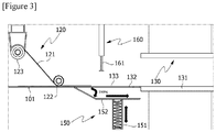
- Figure 3 is a side view of a pressurizing part, a weight measuring part and an image mapping part of an exemplary porous body quality inspection apparatus of the present application.
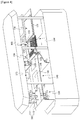
- Figure 4 is a schematic perspective view of an exemplary porous body quality inspection apparatus of the present application.
- the porous body quality inspection apparatus (100) comprises a transporting part (140), a measuring part (110), a pressurizing part (120), a weight measuring part (150), an image mapping part (130), an operation part (not shown), a product selection part (160) and a display part (170).
- each part of the porous body quality inspection apparatus continuously performs a predetermined function on the porous body transported by the transporting part (140) including a conveyor belt (141) equipped with an opening (142), whereby the quality inspection of the porous body (101) can be continuously performed.
- the porous body quality inspection apparatus (100) comprises a measuring part (110).
- the measuring part (110) may comprise a holder (112) on which a gas diffusion layer (113) is disposed and a contact resistance measurement sensor (111) in order to measure a contact resistance between the porous body (101) and the gas diffusion layer (113).
- the contact resistance can be measured by contacting the gas diffusion layer (113) disposed on the holder (112) with one side or both sides of the porous body (101).
- the measurement can be performed by contacting the gas diffusion layer (113) disposed on the holder (112) with both sides of the porous body (101) through the opening (142) equipped in the conveyor belt (141), as shown in Figure 2 .
- the measuring part (110) may comprise a gauge sensor (114) for measuring the thickness of the porous body (101).
- the thickness measurement of the porous body (101) can be performed by measuring the thickness of the porous body by the gauge sensor (114) through the opening (142) equipped in the conveyor belt (141), as shown in Figure 2 .
- the porous body quality inspection apparatus comprises a pressurizing part (120) for pressurizing the pressure-sensitive discoloration base material (121) on the porous body (101).
- the pressure-sensitive discoloration base material (121) of the present application means a base material whose color changes by mechanical pressure.
- the kind of the pressure-sensitive discoloration base material (121) is not particularly limited as long as the color of the portion to which the pressure is applied is discolored, but for example, a carbon/carbonizing paper, a pressure-sensitive coating film, a carbonic paper or a film and paper in which microcapsules of a color developer layer are destroyed by pressure and thus the color of the contact surface is changed can be used.
- the pressurizing part (120) may comprise a transport roller for safely placing the pressure-sensitive discoloration base material (121) on the porous body (101), and a pressure roller (122) for pressurizing the pressure-sensitive discoloration base material (121) safely placed on the porous body (101) at a predetermined pressure.
- the pressurizing part (120) serves to contact the porous body (101) with the pressure-sensitive discoloration base material (121) by pressurizing the pressure-sensitive discoloration base material (121) safely placed on the porous body (101) at a predetermined pressure.
- the predetermined pressure is a pressure corresponding to a pressure of the porous body (101) in contact with the gas diffusion layer in the fuel cell stack, which means a pressure equal to or having a small error that can be regarded as equal to a pressure that the porous body (101) receives by the gas diffusion layer in the fuel cell stack.
- the porous body (101) and the pressure-sensitive discoloration base material (121) are brought into contact with the porous body (101) at a contact area similar to an aspect that the porous body (101) is in contact with the gas diffusion layer in the fuel cell stack. Therefore, if the area of the discolored region of the pressurized pressure-sensitive discoloration base material (121) is measured, the area of the porous body (101) contacting the gas diffusion layer in the fuel cell stack can be measured.
- the pressure that the pressurizing part (120) applies to the pressure-sensitive discoloration base material (121) may be adjusted, for example, by adjusting the position of the pressure roller (122) located at the upper part of the conveyor belt (141). The closer the pressure roller (122) is to the conveyor belt (141), the stronger pressure is applied to the pressure-sensitive discoloration base material (121) by the porous body (101) passing between the pressure roller (122) and the conveyor belt (141).
- the quality inspection apparatus of the present application can control the pressure applied by the pressurizing part (120) even if the specification of the fuel cell stack is changed, it can make the contact area that the porous body (101) is in contact with the pressure-sensitive discoloration base material (121) similar to the contact area that the porous body is in contact with the gas diffusion layer in the fuel cell stack.
- the porous body quality inspection apparatus may comprise a weight measuring part (150) for measuring the weight of the porous body (101).
- the weight measuring part (150) may comprise a tray (152) supported by an elastic body (151), in which the porous body (101) transported by the conveyor belt (141) is stacked and housed.
- the weight measuring part (150) may inspect the quality of the porous body by measuring the accumulated weight of the porous body (101) transported to the tray (152) through the porous body discharge penetration region (133) equipped in a collection part (132) of the image mapping part (130) based on the up-and-down movement of the elastic body (151), as shown in Figures 3 and 4 .
- the porous body quality inspection apparatus of the present application comprises an image mapping part (130) for calculating a contact area between the pressure-sensitive discoloration base material (121) and the porous body (101) based on the discolored region of the pressurized pressure-sensitive discoloration base material. Since the pressurizing part (120) pressurizes the pressure-sensitive discoloration base material (121) safely placed on the porous body (101) to the pressure corresponding to the pressure that the porous body receives by the gas diffusion layer in the fuel cell stack, the contact area between the porous body (101) and the pressure-sensitive discoloration base material (121) calculated in the image mapping part (130) is similar to the area in which the porous body contacts the gas diffusion layer in the fuel cell stack.
- the image mapping part (130) of the present application may comprise a collection part (132) for separately collecting the pressurized pressure-sensitive discoloration base material (121) from the porous body (101), a porous body discharge penetration region (133) and a scanner (131) for scanning the discolored region of the pressure-sensitive discoloration base material (121), as shown in Figure 4 .
- the porous body (101) transported by the transporting part (140) is housed in the tray (152) of the weight measuring part (150) through the porous body discharge penetration region (133) equipped in the collection part (132), and the pressure-sensitive discoloration base material (121) passing through the pressurizing part (120) via the pressure-sensitive discoloration base material transport roller (123) and the transporting part (140) is separated from the porous body (101) and collected into the image mapping part (130), while being supported by the collection part (132), as shown in Figure 3 .
- the porous body quality inspection apparatus of the present application comprises an operation part (not shown) for performing an operation of an interfacial contact resistance between the porous body and the gas diffusion layer (113) based on the contact resistance measured by the measuring part (110) and the contact area calculated by the image mapping part (130).
- interfacial contact resistance means a contact resistance generated by contact of two objects multiplied by a contact area of two objects.
- ICR is an interfacial contact resistance between the porous body and the gas diffusion layer
- GDL is a contact resistance between the porous body and the gas diffusion layer
- AC actual is a contact area between the pressure-sensitive discoloration base material and the porous body calculated based on the discolored region of the pressurized pressure-sensitive discoloration base material.
- the porous body quality inspection apparatus of the present application may further comprise a product selection part (160) including a vacuum adsorption part (161).
- the product selection part (160) may serve to spatially separate a porous body that does not satisfy a predetermined criterion from a porous body that satisfies a predetermined criterion, and for example, it may serve to remove a porous body, which does not satisfy the predetermined criterion, housed in the tray (152) from the tray (152).
- the porous body quality inspection apparatus of the present application may further comprise a display part (170) that outputs one or more of a contact resistance, a contact area and an interfacial contact resistance.
- the display part (170) outputs matters concerning the quality of the porous body such as the contact resistance, the contact area and the interfacial contact resistance, so that information on the quality of the porous body can be visually confirmed.
- the present application also relates to a method for inspecting quality of a porous body.
- the method for inspecting quality of a porous body of the present application comprises steps of measuring a contact resistance between a porous body and a gas diffusion layer, pressurizing a pressure-sensitive discoloration base material placed on the porous body to a predetermined pressure, calculating a contact area between the pressure-sensitive discoloration base material and the porous body based on the discolored region of the pressurized pressure-sensitive discoloration base material, and performing an operation of an interfacial contact resistance between the porous body and the gas diffusion layer based on the contact resistance and the contact area.
- the method for inspecting quality of a porous body of the present application comprises a step of measuring a contact resistance between a porous body and a gas diffusion layer.
- the measurement of the contact resistance between the porous body and the gas diffusion layer can be performed by measuring the contact resistance generated by contacting the gas diffusion layer used in the fuel cell into contact with the porous body.
- the measurement of the contact resistance may be performed by contacting the gas diffusion layer of the contact resistance sensor including the holder, in which the gas diffusion layer is disposed, with the porous body.
- the method for inspecting quality of a porous body of the present application comprises a step of pressurizing a pressure-sensitive discoloration base material safely placed on the porous body to a predetermined pressure.
- the pressure-sensitive discoloration base material can be safely placed on the porous body by the pressure-sensitive discoloration base material transport roller, and the pressure-sensitive discoloration base material safely placed on the porous body can be pressurized by the pressure roller.
- the predetermined pressure is a pressure that corresponds to a pressure of the porous body in contact with the gas diffusion layer in the fuel cell stack, which means a pressure equal to or having a small error that can be regarded as equal to a pressure that the porous body receives by the gas diffusion layer in the fuel cell stack.
- the porous body and the pressure-sensitive discoloration base material are brought into contact with the porous body at a contact area similar to an aspect that the porous body is in contact with the gas diffusion layer in the fuel cell stack. Therefore, if the area of the discolored region of the pressurized pressure-sensitive discoloration base material is measured, the area of the porous body contacting the gas diffusion layer in the fuel cell stack can be measured.
- the method for inspecting quality of a porous body of the present application comprises a step of calculating a contact area between the pressure-sensitive discoloration base material and the porous body based on the discolored region of the pressurized pressure-sensitive discoloration base material.
- a method of scanning the discolored region of the pressurized pressure-sensitive discoloration base material with a scanner and then calculating the area of the discolored region can be used for the calculation of the contact area.
- the method for inspecting quality of a porous body of the present application comprises a step of performing an operation of an interfacial contact resistance between the porous body and the gas diffusion layer based on the contact resistance and the contact area.
- ICR is an interfacial contact resistance between the porous body and the gas diffusion layer
- GDL is a contact resistance between the porous body and the gas diffusion layer
- AC actual is a contact area between the pressure-sensitive discoloration base material and the porous body calculated based on the discolored region of the pressurized pressure-sensitive discoloration base material.
- the thermal and electrical losses of the fuel cell stack by the porous body can be quantified, and the manufacturing tolerance and the surface pressure uniformity of the porous body can be quantitatively confirmed.
Landscapes
- Chemical & Material Sciences (AREA)
- Electrochemistry (AREA)
- Chemical Kinetics & Catalysis (AREA)
- Life Sciences & Earth Sciences (AREA)
- Physics & Mathematics (AREA)
- Pathology (AREA)
- Immunology (AREA)
- General Physics & Mathematics (AREA)
- General Health & Medical Sciences (AREA)
- Biochemistry (AREA)
- Analytical Chemistry (AREA)
- Health & Medical Sciences (AREA)
- General Chemical & Material Sciences (AREA)
- Engineering & Computer Science (AREA)
- Manufacturing & Machinery (AREA)
- Dispersion Chemistry (AREA)
- Sustainable Development (AREA)
- Sustainable Energy (AREA)
- Fuel Cell (AREA)
- Investigating Or Analyzing Materials By The Use Of Electric Means (AREA)
- Testing Resistance To Weather, Investigating Materials By Mechanical Methods (AREA)
Abstract
Description
- The present application relates to a porous body quality inspection apparatus and a method for inspecting quality of a porous body.
- This application claims the benefit of priority based on Korean Patent Application No.
10-2017-0019120 filed on February 13, 2017 - Generally, a fuel cell is an energy conversion device that generates electrical energy through an electrochemical reaction between a fuel and an oxidizer and has an advantage that power can be consistently generated as long as the fuel is continuously supplied.
- A polymer electrolyte membrane fuel cell (PEMFC) using a polymer membrane capable of permeating hydrogen ions as an electrolyte, has a low operating temperature of about 100°C as compared to other types of fuel cells, and has advantages of high energy conversion efficiency, high output density and fast response characteristics. Besides, since it can be miniaturized, it can be provided as portable, vehicle and household power supplies.
- The polymer electrolyte membrane fuel cell stack may comprise a membrane-electrode assembly (MEA) having an electrode layer formed by applying an anode and a cathode around an electrolyte membrane composed of a polymer material, a gas diffusion layer (GDL) for serving to distribute reaction gases evenly and to transfer generated electric energy, a separating plate (bipolar plate) for supplying the reaction gases to the gas diffusion layer and discharging generated water, and a gasket for preventing leakage of the reaction gases and cooling water between the electrolyte membrane and the separating plate.
- Conventional separators each provided with reaction gas channels and cooling water channels on both sides have technical problems of water transfer imbalance in the fuel cell and high mass transfer resistance (usually diffusion resistance) of the reaction gas in the reaction surface, in the high power zone.
- Recently, a separator (hereinafter also referred to as a 'porous body'), to which a metal foam or a metal mesh and the like is applied, is proposed to improve performance of a fuel cell through reduction of diffusion resistance in a high power operation zone. The porous body equipped on the surface of the separator in contact with the gas diffusion layer serves to lower the diffusion resistance by allowing the gas diffusion layer and the separator to be partially spaced apart from each other and causing convection and diffusion actions in the spaced space.
- However, since the spaced space between the porous body and the gas diffusion layer has a problem that it is difficult to predict interfacial contact resistance between the porous body and the gas diffusion layer, it is necessary to study a method of easily determining the interfacial contact resistance before applying the porous body to the fuel cell stack.
- The present application provides a porous body quality inspection apparatus and a method for inspecting quality of a porous body, which can inspect quality of a porous body by determining interfacial contact resistance between a porous body and a gas diffusion layer generated when the porous body is applied to a fuel cell stack before applying the porous body to the fuel cell stack.
- To solve the above-described problem, according to one embodiment of the present invention, there is provided a porous body quality inspection apparatus comprising a contact resistance measuring part of a porous body with a gas diffusion layer, a pressurizing part for pressurizing a pressure-sensitive discoloration base material on the porous body, an image mapping part for calculating a contact area between the pressure-sensitive discoloration base material and the porous body and an operation part for performing an operation of an interfacial contact resistance between the porous body and the gas diffusion layer.
- According to another embodiment of the present invention, there is provided a method for inspecting quality of a porous body comprising steps of measuring a contact resistance between a porous body and a gas diffusion layer, pressurizing a pressure-sensitive discoloration base material safely placed on the porous body to a predetermined pressure, calculating a contact area between the pressure-sensitive discoloration base material and the porous body based on the discolored region of the pressurized pressure-sensitive discoloration base material, and performing an operation of an interfacial contact resistance between the porous body and the gas diffusion layer based on the contact resistance and the contact area.
- The porous body quality inspection apparatus and the method for inspecting quality of a porous body according to one embodiment of the present invention have the following effects.
- Thermal and electrical loss of the fuel cell stack by the porous body can be quantified, manufacturing tolerance and surface pressure uniformity of the porous body can be quantitatively confirmed, a performance deviation between the individual fuel cell stacks can be reduced, and production management costs can be reduced by accumulating a quality inspection database of the porous body by a specific design.
-
-
Figure 1 is a schematic side view of an exemplary porous body quality inspection apparatus of the present application. -
Figure 2 is a view showing a measuring part of an exemplary porous body quality inspection apparatus of the present application. -
Figure 3 is a partial side view of an exemplary porous body quality inspection apparatus of the present application. -
Figure 4 is a schematic perspective view of an exemplary porous body quality inspection apparatus of the present application. -
Figure 5 is a view showing a portion discolored by a pressurizing part of a pressure-sensitive discoloration base material of the present application. - Hereinafter, the quality inspection apparatus according to one embodiment of the present invention will be described in detail with reference to the accompanying drawings.
- In addition, the same or similar reference numerals are given to the same or corresponding components regardless of reference numerals, of which redundant explanations will be omitted, and for convenience of explanation, the size and shape of each constituent member as shown may be exaggerated or reduced.
-
Figure 1 is a schematic side view of an exemplary porous body quality inspection apparatus of the present application. -
Figure 2 is a view showing a measuring part of an exemplary porous body quality inspection apparatus of the present application. -
Figure 3 is a side view of a pressurizing part, a weight measuring part and an image mapping part of an exemplary porous body quality inspection apparatus of the present application. -
Figure 4 is a schematic perspective view of an exemplary porous body quality inspection apparatus of the present application. - As shown in
Figure1 , the porous body quality inspection apparatus (100) according to one embodiment of the present application comprises a transporting part (140), a measuring part (110), a pressurizing part (120), a weight measuring part (150), an image mapping part (130), an operation part (not shown), a product selection part (160) and a display part (170). In one embodiment of the present application, each part of the porous body quality inspection apparatus continuously performs a predetermined function on the porous body transported by the transporting part (140) including a conveyor belt (141) equipped with an opening (142), whereby the quality inspection of the porous body (101) can be continuously performed. Hereinafter, each part of the quality inspection apparatus according to one embodiment of the present application will be described in detail. - Referring to
Figure 1 , the porous body quality inspection apparatus (100) comprises a measuring part (110). In one example, the measuring part (110) may comprise a holder (112) on which a gas diffusion layer (113) is disposed and a contact resistance measurement sensor (111) in order to measure a contact resistance between the porous body (101) and the gas diffusion layer (113). The contact resistance can be measured by contacting the gas diffusion layer (113) disposed on the holder (112) with one side or both sides of the porous body (101). Particularly, when the contact resistance is measured by contacting the gas diffusion layer (113) with both sides of the porous body (101), the measurement can be performed by contacting the gas diffusion layer (113) disposed on the holder (112) with both sides of the porous body (101) through the opening (142) equipped in the conveyor belt (141), as shown inFigure 2 . - The measuring part (110) may comprise a gauge sensor (114) for measuring the thickness of the porous body (101). The thickness measurement of the porous body (101) can be performed by measuring the thickness of the porous body by the gauge sensor (114) through the opening (142) equipped in the conveyor belt (141), as shown in
Figure 2 . - The porous body quality inspection apparatus according to one embodiment of the present application comprises a pressurizing part (120) for pressurizing the pressure-sensitive discoloration base material (121) on the porous body (101). The pressure-sensitive discoloration base material (121) of the present application means a base material whose color changes by mechanical pressure. The kind of the pressure-sensitive discoloration base material (121) is not particularly limited as long as the color of the portion to which the pressure is applied is discolored, but for example, a carbon/carbonizing paper, a pressure-sensitive coating film, a carbonic paper or a film and paper in which microcapsules of a color developer layer are destroyed by pressure and thus the color of the contact surface is changed can be used. In one example, the pressurizing part (120) may comprise a transport roller for safely placing the pressure-sensitive discoloration base material (121) on the porous body (101), and a pressure roller (122) for pressurizing the pressure-sensitive discoloration base material (121) safely placed on the porous body (101) at a predetermined pressure.
- The pressurizing part (120) serves to contact the porous body (101) with the pressure-sensitive discoloration base material (121) by pressurizing the pressure-sensitive discoloration base material (121) safely placed on the porous body (101) at a predetermined pressure. The predetermined pressure is a pressure corresponding to a pressure of the porous body (101) in contact with the gas diffusion layer in the fuel cell stack, which means a pressure equal to or having a small error that can be regarded as equal to a pressure that the porous body (101) receives by the gas diffusion layer in the fuel cell stack. When the pressure-sensitive discoloration base material (121) safely placed on the porous body (101) is pressurized to the pressure as above, the porous body (101) and the pressure-sensitive discoloration base material (121) are brought into contact with the porous body (101) at a contact area similar to an aspect that the porous body (101) is in contact with the gas diffusion layer in the fuel cell stack. Therefore, if the area of the discolored region of the pressurized pressure-sensitive discoloration base material (121) is measured, the area of the porous body (101) contacting the gas diffusion layer in the fuel cell stack can be measured.
- The pressure that the pressurizing part (120) applies to the pressure-sensitive discoloration base material (121) may be adjusted, for example, by adjusting the position of the pressure roller (122) located at the upper part of the conveyor belt (141). The closer the pressure roller (122) is to the conveyor belt (141), the stronger pressure is applied to the pressure-sensitive discoloration base material (121) by the porous body (101) passing between the pressure roller (122) and the conveyor belt (141). Since the quality inspection apparatus of the present application can control the pressure applied by the pressurizing part (120) even if the specification of the fuel cell stack is changed, it can make the contact area that the porous body (101) is in contact with the pressure-sensitive discoloration base material (121) similar to the contact area that the porous body is in contact with the gas diffusion layer in the fuel cell stack.
- In one embodiment of the porous body quality inspection apparatus of the present application, the porous body quality inspection apparatus may comprise a weight measuring part (150) for measuring the weight of the porous body (101). In one example, the weight measuring part (150) may comprise a tray (152) supported by an elastic body (151), in which the porous body (101) transported by the conveyor belt (141) is stacked and housed. In one example, the weight measuring part (150) may inspect the quality of the porous body by measuring the accumulated weight of the porous body (101) transported to the tray (152) through the porous body discharge penetration region (133) equipped in a collection part (132) of the image mapping part (130) based on the up-and-down movement of the elastic body (151), as shown in
Figures 3 and4 . - The porous body quality inspection apparatus of the present application comprises an image mapping part (130) for calculating a contact area between the pressure-sensitive discoloration base material (121) and the porous body (101) based on the discolored region of the pressurized pressure-sensitive discoloration base material. Since the pressurizing part (120) pressurizes the pressure-sensitive discoloration base material (121) safely placed on the porous body (101) to the pressure corresponding to the pressure that the porous body receives by the gas diffusion layer in the fuel cell stack, the contact area between the porous body (101) and the pressure-sensitive discoloration base material (121) calculated in the image mapping part (130) is similar to the area in which the porous body contacts the gas diffusion layer in the fuel cell stack. In one example, the image mapping part (130) of the present application may comprise a collection part (132) for separately collecting the pressurized pressure-sensitive discoloration base material (121) from the porous body (101), a porous body discharge penetration region (133) and a scanner (131) for scanning the discolored region of the pressure-sensitive discoloration base material (121), as shown in
Figure 4 . In one embodiment of the porous quality inspection apparatus of the present application, the porous body (101) transported by the transporting part (140) is housed in the tray (152) of the weight measuring part (150) through the porous body discharge penetration region (133) equipped in the collection part (132), and the pressure-sensitive discoloration base material (121) passing through the pressurizing part (120) via the pressure-sensitive discoloration base material transport roller (123) and the transporting part (140) is separated from the porous body (101) and collected into the image mapping part (130), while being supported by the collection part (132), as shown inFigure 3 . - The porous body quality inspection apparatus of the present application comprises an operation part (not shown) for performing an operation of an interfacial contact resistance between the porous body and the gas diffusion layer (113) based on the contact resistance measured by the measuring part (110) and the contact area calculated by the image mapping part (130). In the present application, the term "interfacial contact resistance" means a contact resistance generated by contact of two objects multiplied by a contact area of two objects. The operation part performs an operation of an interfacial contact resistance by Equation 1 below.

- In Equation 1, ICR is an interfacial contact resistance between the porous body and the gas diffusion layer, RBP|GDL is a contact resistance between the porous body and the gas diffusion layer, and ACactual is a contact area between the pressure-sensitive discoloration base material and the porous body calculated based on the discolored region of the pressurized pressure-sensitive discoloration base material. By performing an operation of the interfacial contact resistance between the porous body and the gas diffusion layer (112) through the process as above, the thermal and electrical losses of the fuel cell stack by the porous body can be predicted, whereby the fuel cell stack having excellent reliability, productivity and power generation efficiency can be manufactured.
- In one example, the porous body quality inspection apparatus of the present application may further comprise a product selection part (160) including a vacuum adsorption part (161). The product selection part (160) may serve to spatially separate a porous body that does not satisfy a predetermined criterion from a porous body that satisfies a predetermined criterion, and for example, it may serve to remove a porous body, which does not satisfy the predetermined criterion, housed in the tray (152) from the tray (152).
- In one example, the porous body quality inspection apparatus of the present application may further comprise a display part (170) that outputs one or more of a contact resistance, a contact area and an interfacial contact resistance. The display part (170) outputs matters concerning the quality of the porous body such as the contact resistance, the contact area and the interfacial contact resistance, so that information on the quality of the porous body can be visually confirmed.
- The present application also relates to a method for inspecting quality of a porous body.
- The method for inspecting quality of a porous body of the present application comprises steps of measuring a contact resistance between a porous body and a gas diffusion layer, pressurizing a pressure-sensitive discoloration base material placed on the porous body to a predetermined pressure, calculating a contact area between the pressure-sensitive discoloration base material and the porous body based on the discolored region of the pressurized pressure-sensitive discoloration base material, and performing an operation of an interfacial contact resistance between the porous body and the gas diffusion layer based on the contact resistance and the contact area.
- Hereinafter, each step of the method for inspecting quality of a porous body will be described in detail.
- The method for inspecting quality of a porous body of the present application comprises a step of measuring a contact resistance between a porous body and a gas diffusion layer. The measurement of the contact resistance between the porous body and the gas diffusion layer can be performed by measuring the contact resistance generated by contacting the gas diffusion layer used in the fuel cell into contact with the porous body. In one example, the measurement of the contact resistance may be performed by contacting the gas diffusion layer of the contact resistance sensor including the holder, in which the gas diffusion layer is disposed, with the porous body.
- The method for inspecting quality of a porous body of the present application comprises a step of pressurizing a pressure-sensitive discoloration base material safely placed on the porous body to a predetermined pressure. In one example, the pressure-sensitive discoloration base material can be safely placed on the porous body by the pressure-sensitive discoloration base material transport roller, and the pressure-sensitive discoloration base material safely placed on the porous body can be pressurized by the pressure roller. The predetermined pressure is a pressure that corresponds to a pressure of the porous body in contact with the gas diffusion layer in the fuel cell stack, which means a pressure equal to or having a small error that can be regarded as equal to a pressure that the porous body receives by the gas diffusion layer in the fuel cell stack. When the pressure-sensitive discoloration base material safely placed on the porous body is pressurized to the pressure as above, the porous body and the pressure-sensitive discoloration base material are brought into contact with the porous body at a contact area similar to an aspect that the porous body is in contact with the gas diffusion layer in the fuel cell stack. Therefore, if the area of the discolored region of the pressurized pressure-sensitive discoloration base material is measured, the area of the porous body contacting the gas diffusion layer in the fuel cell stack can be measured.
- The method for inspecting quality of a porous body of the present application comprises a step of calculating a contact area between the pressure-sensitive discoloration base material and the porous body based on the discolored region of the pressurized pressure-sensitive discoloration base material. In one example, a method of scanning the discolored region of the pressurized pressure-sensitive discoloration base material with a scanner and then calculating the area of the discolored region can be used for the calculation of the contact area.
- The method for inspecting quality of a porous body of the present application comprises a step of performing an operation of an interfacial contact resistance between the porous body and the gas diffusion layer based on the contact resistance and the contact area. The interfacial contact resistance can be subjected to an operation by Equation 1 below.

- In Equation 1, ICR is an interfacial contact resistance between the porous body and the gas diffusion layer, RBP|GDL is a contact resistance between the porous body and the gas diffusion layer, and ACactual is a contact area between the pressure-sensitive discoloration base material and the porous body calculated based on the discolored region of the pressurized pressure-sensitive discoloration base material. By performing an operation of the interfacial contact resistance between the porous body and the gas diffusion layer, the thermal and electrical losses of the fuel cell stack by the porous body can be predicted, whereby the fuel cell stack having excellent reliability, productivity and power generation efficiency can be manufactured.
- The preferred embodiments of the present invention as described above are disclosed for exemplary purpose, where those skilled in the art having ordinary knowledge for the present invention can make various corrections, modifications and additions within idea and scope of the present invention, and such a correction, modification and addition should be considered as falling within the scope of the following claims.
- The preferred embodiments of the present invention as described above are disclosed for exemplary purpose, where those skilled in the art having ordinary knowledge for the present invention can make various corrections, modifications and additions within idea and scope of the present invention, and such a correction, modification and addition should be considered as falling within the scope of the following claims.
- According to the porous body quality inspection apparatus and the method for inspecting quality of a porous body related to the present invention, the thermal and electrical losses of the fuel cell stack by the porous body can be quantified, and the manufacturing tolerance and the surface pressure uniformity of the porous body can be quantitatively confirmed.
Claims (15)
- A porous body quality inspection apparatus comprising:a measuring part for measuring a contact resistance between a porous body and a gas diffusion layer;a pressurizing part for pressurizing a pressure-sensitive discoloration base material on the porous body;an image mapping part for calculating a contact area between the pressure-sensitive discoloration base material and the porous body based on the discolored region of the pressurized pressure-sensitive discoloration base material;a transporting part for transporting the porous body and the pressure-sensitive discoloration base material andan operation part for performing an operation of an interfacial contact resistance between the porous body and the gas diffusion layer on the basis of the contact resistance and the contact area.
- The porous body quality inspection apparatus according to claim 1, wherein the operation part performs an operation of an interfacial contact resistance by Equation 1 below:

- The porous body quality inspection apparatus according to claim 1, wherein the measuring part comprises a holder on which a gas diffusion layer is disposed and a contact resistance measurement sensor.
- The porous body quality inspection apparatus according to claim 1, wherein the pressurizing part comprises a pressure-sensitive discoloration base material transport roller and a pressure roller.
- The porous body quality inspection apparatus according to claim 4, wherein the pressurizing part pressurizes the pressure-sensitive discoloration base material safely placed on the porous body by the transport roller to a predetermined pressure by the pressure roller.
- The porous body quality inspection apparatus according to claim 5, wherein the predetermined pressure is a pressure corresponding to a pressure of the porous body in contact with the gas diffusion layer in the fuel cell stack.
- The porous body quality inspection apparatus according to claim 1, wherein the image mapping part comprises a collection part for separately collecting the pressurized pressure-sensitive discoloration base material from the porous body and a scanner for scanning the discolored region of the collected pressure-sensitive discoloration base material.
- The porous body quality inspection apparatus according to claim 1, wherein the measuring part comprises a gauge sensor for measuring a thickness of the porous body.
- The porous body quality inspection apparatus according to claim 1, further comprising a weight measuring part for measuring a weight of the porous body.
- The porous body quality inspection apparatus according to claim 9, wherein the weight measuring part comprises a tray supported by an elastic body, in which the porous body is stacked and housed.
- The porous body quality inspection apparatus according to claim 1, further comprising a product selection part including a vacuum adsorption part.
- The porous body quality inspection apparatus according to claim 1, comprising a display part for outputting one or more of the contact resistance, the contact area and the interfacial contact resistance.
- A method for inspecting quality of a porous body comprising steps of:measuring a contact resistance between a porous body and a gas diffusion layer;pressurizing a pressure-sensitive discoloration base material safely placed on the porous body to a predetermined pressure:calculating a contact area between the pressure-sensitive discoloration base material and the porous body based on the discolored region of the pressurized pressure-sensitive discoloration base material andperforming an operation of an interfacial contact resistance between the porous body and the gas diffusion layer based on the contact resistance and the contact area.
- The method for inspecting quality of a porous body according to claim 13, wherein the step of performing an operation of an interfacial contact resistance performs the operation of the interfacial contact resistance by Equation 1 below:

- The method for inspecting quality of a porous body according to claim 13, wherein the predetermined pressure is a pressure corresponding to a pressure of the porous body in contact with the gas diffusion layer in the fuel cell stack.
Applications Claiming Priority (2)
| Application Number | Priority Date | Filing Date | Title |
|---|---|---|---|
| KR1020170019120A KR102079134B1 (en) | 2017-02-13 | 2017-02-13 | Apparatus for examining quality of porous body and method for quality examination of porous body |
| PCT/KR2018/001806 WO2018147695A1 (en) | 2017-02-13 | 2018-02-12 | Apparatus for inspecting quality of porous body and method for inspecting quality of porous body |
Publications (3)
| Publication Number | Publication Date |
|---|---|
| EP3578953A1 true EP3578953A1 (en) | 2019-12-11 |
| EP3578953A4 EP3578953A4 (en) | 2020-02-26 |
| EP3578953B1 EP3578953B1 (en) | 2023-04-05 |
Family
ID=63107749
Family Applications (1)
| Application Number | Title | Priority Date | Filing Date |
|---|---|---|---|
| EP18751648.9A Active EP3578953B1 (en) | 2017-02-13 | 2018-02-12 | Apparatus for inspecting quality of porous body and method for inspecting quality of porous body |
Country Status (6)
| Country | Link |
|---|---|
| US (1) | US11495837B2 (en) |
| EP (1) | EP3578953B1 (en) |
| JP (1) | JP6879525B2 (en) |
| KR (1) | KR102079134B1 (en) |
| CN (1) | CN110268244B (en) |
| WO (1) | WO2018147695A1 (en) |
Families Citing this family (5)
| Publication number | Priority date | Publication date | Assignee | Title |
|---|---|---|---|---|
| KR102532993B1 (en) * | 2022-11-30 | 2023-05-16 | 주식회사 엔비컨스 | System for measuring thickness and air permeability of film |
| KR20240097159A (en) * | 2022-12-20 | 2024-06-27 | 주식회사 엘지에너지솔루션 | Apparatus for measuring resistance of electrode |
| CN116359286B (en) * | 2023-03-20 | 2026-02-27 | 同济大学 | A method, apparatus and application for evaluating the contact state of a gas diffusion layer interface. |
| WO2025100890A1 (en) * | 2023-11-06 | 2025-05-15 | 주식회사 엘지에너지솔루션 | Apparatus for manufacturing battery |
| CN118225614B (en) * | 2024-05-23 | 2024-08-27 | 深圳市通用氢能科技有限公司 | System and method for testing durability of gas diffusion layer |
Family Cites Families (34)
| Publication number | Priority date | Publication date | Assignee | Title |
|---|---|---|---|---|
| US4377786A (en) * | 1980-08-06 | 1983-03-22 | Radco Industries, Inc. | Battery testing apparatus |
| US7592089B2 (en) * | 2000-08-31 | 2009-09-22 | Gm Global Technology Operations, Inc. | Fuel cell with variable porosity gas distribution layers |
| JP4346874B2 (en) * | 2002-08-08 | 2009-10-21 | 株式会社大阪チタニウムテクノロジーズ | Porous conductive plate |
| TW200519150A (en) * | 2003-12-05 | 2005-06-16 | Showa Denko Kk | Conductive resin composition and molded product thereof |
| JP2006000605A (en) | 2004-06-17 | 2006-01-05 | Tetsuo Higashikura | Vase |
| JP5266304B2 (en) * | 2005-02-23 | 2013-08-21 | パナソニック株式会社 | Fuel cell separator and method of manufacturing the same |
| JP2006244750A (en) * | 2005-03-01 | 2006-09-14 | Toyota Motor Corp | FUEL CELL STACK, FUEL CELL, METHOD FOR MANUFACTURING THE SAME, AND METHOD FOR ADJUSTING WEIGHT |
| JP4971022B2 (en) * | 2006-07-12 | 2012-07-11 | 日東電工株式会社 | Method for producing multilayer laminated film |
| JP2008041304A (en) * | 2006-08-02 | 2008-02-21 | Matsushita Electric Ind Co Ltd | Fuel cell separator and fuel cell using the same |
| JP2008157721A (en) * | 2006-12-22 | 2008-07-10 | Toyota Motor Corp | Surface contact situation measuring device and measuring method |
| KR100902316B1 (en) | 2007-12-11 | 2009-06-12 | 한국에너지기술연구원 | Physical property evaluation device to measure length, resistance, differential pressure, etc. according to pressure of gas diffusion layer used in fuel cell |
| CN101576607B (en) * | 2009-06-10 | 2011-04-13 | 北京健翔顺鑫科技有限公司 | Method for detecting nickel-hydrogen battery Diaphragm wet resistance and device thereof |
| US9499703B2 (en) * | 2009-11-30 | 2016-11-22 | Konica Minolta, Inc. | Ink-jet image forming method and ink-jet ink set |
| KR101242986B1 (en) * | 2010-03-22 | 2013-03-12 | 현대하이스코 주식회사 | Metal separator for fuel cell and method of manufacturing the same |
| DE102010016502A1 (en) * | 2010-04-19 | 2011-10-20 | Phoenix Conveyor Belt Systems Gmbh | Device for nondestructive inspection of a conveyor belt by means of high-energy radiation, in particular X-rays |
| EP2615675B1 (en) | 2010-09-10 | 2019-07-24 | Nisshinbo Chemical Inc. | Fuel cell separator |
| US9372588B2 (en) * | 2011-05-19 | 2016-06-21 | Microsoft Technology Licensing, Llc | Pressure-sensitive multi-touch device |
| JP2013058414A (en) * | 2011-09-08 | 2013-03-28 | Shin Etsu Polymer Co Ltd | Fuel cell separator and method for manufacturing the same |
| JP5485358B2 (en) * | 2012-01-06 | 2014-05-07 | 三菱レイヨン株式会社 | Gas diffusion layer for polymer electrolyte fuel cells |
| CN202734800U (en) * | 2012-06-25 | 2013-02-13 | 天津市中马骏腾精密机械制造有限公司 | Full-automatic detection production line for circle-annular part |
| KR101320786B1 (en) | 2012-11-09 | 2013-10-23 | 현대하이스코 주식회사 | Apparatus for measuring of contact resistance and method for measuring of contact resistance of bopolar plate for a fuel cell |
| KR101394118B1 (en) | 2012-12-20 | 2014-05-14 | 현대오트론 주식회사 | Filter seletion method for voltage measurement |
| KR20140085802A (en) * | 2012-12-27 | 2014-07-08 | 현대자동차주식회사 | Method and system for measuring impedance for state diagnosis of fuel cell stack |
| US20140208850A1 (en) * | 2013-01-29 | 2014-07-31 | Geun-Woo Kim | Apparatus and method of detecting a defect of a semiconductor device |
| JP6277653B2 (en) * | 2013-10-03 | 2018-02-14 | 三菱ケミカル株式会社 | Method for producing porous electrode substrate |
| KR101676407B1 (en) * | 2014-09-22 | 2016-11-29 | 주식회사 엘지화학 | Test method for thermal pad and method of fabricating battery module using the same |
| JP2016085921A (en) | 2014-10-28 | 2016-05-19 | Jxエネルギー株式会社 | Cell support and solid oxide fuel cell |
| KR101666566B1 (en) * | 2015-03-24 | 2016-10-17 | 주식회사 리빙케어 | Fuel cell gas diffusion layer quality automatic test device |
| JP6358439B2 (en) * | 2015-05-28 | 2018-07-18 | 京セラドキュメントソリューションズ株式会社 | Image forming apparatus, image forming method, and control program |
| KR20170019120A (en) | 2015-08-11 | 2017-02-21 | 동우 화인켐 주식회사 | Hard Coating Composition and Hard Coating Film Using the Same |
| US10647022B2 (en) * | 2015-11-09 | 2020-05-12 | Seiko Epson Corporation | Sheet manufacturing apparatus and sheet manufacturing method |
| CN105572474B (en) * | 2015-12-14 | 2018-12-28 | 新源动力股份有限公司 | A device for testing the contact resistance of a bipolar plate for a proton exchange membrane fuel cell |
| CN105651432A (en) * | 2015-12-30 | 2016-06-08 | 新源动力股份有限公司 | Proton exchange membrane fuel cell contact state characterization method |
| US10137690B2 (en) * | 2016-01-29 | 2018-11-27 | Canon Kabushiki Kaisha | Ink jet recording apparatus and ink jet recording method |
-
2017
- 2017-02-13 KR KR1020170019120A patent/KR102079134B1/en active Active
-
2018
- 2018-02-12 CN CN201880010485.9A patent/CN110268244B/en active Active
- 2018-02-12 WO PCT/KR2018/001806 patent/WO2018147695A1/en not_active Ceased
- 2018-02-12 JP JP2019541274A patent/JP6879525B2/en active Active
- 2018-02-12 US US16/483,493 patent/US11495837B2/en active Active
- 2018-02-12 EP EP18751648.9A patent/EP3578953B1/en active Active
Also Published As
| Publication number | Publication date |
|---|---|
| JP6879525B2 (en) | 2021-06-02 |
| CN110268244B (en) | 2024-05-24 |
| JP2020509528A (en) | 2020-03-26 |
| EP3578953B1 (en) | 2023-04-05 |
| US11495837B2 (en) | 2022-11-08 |
| CN110268244A (en) | 2019-09-20 |
| WO2018147695A1 (en) | 2018-08-16 |
| KR102079134B1 (en) | 2020-02-19 |
| US20200020988A1 (en) | 2020-01-16 |
| EP3578953A4 (en) | 2020-02-26 |
| KR20180093276A (en) | 2018-08-22 |
Similar Documents
| Publication | Publication Date | Title |
|---|---|---|
| EP3578953B1 (en) | Apparatus for inspecting quality of porous body and method for inspecting quality of porous body | |
| US10727519B2 (en) | Manufacturing method and apparatus for fuel cell stack | |
| CA3002453C (en) | Method for producing fuel cell separator | |
| JP5936976B2 (en) | Operation method of fuel cell | |
| CN102171879A (en) | Fuel cell system and fuel cell state detection method | |
| US20080197857A1 (en) | Multi-mea test station and multi-mea test method using the same | |
| US11876271B2 (en) | Method and apparatus for manufacturing power generating cell stack body | |
| JP5180948B2 (en) | Fuel cell stack | |
| US20050153192A1 (en) | Fuel cell | |
| US7223492B2 (en) | Laminated structure of flat plate type solid oxide fuel cell | |
| US8154243B2 (en) | Fuel cell potential measuring apparatus and manufacturing method therefor | |
| US10283784B2 (en) | Fuel cell for detecting a pollutant | |
| US12247308B2 (en) | Electrochemical cell, cell operation system and cell operation method | |
| JP4773055B2 (en) | FUEL CELL STACK, SEPARATOR INTERMEDIATE AND SEPARATOR MANUFACTURING METHOD | |
| EP2249423A1 (en) | Method for controlling the flow rate of fuel supplied to a fuel cell, fuel supply device, and fuel cell system using the same | |
| US9496579B2 (en) | Fuel cell limiting the phenomenon of corrosion | |
| JP2003151603A (en) | Short circuit inspection method and short circuit inspection device for membrane-electrode assembly | |
| JP5945466B2 (en) | Potential measurement device for fuel cell | |
| JP2006278246A (en) | Control method of fuel cell stack | |
| JP2006202735A (en) | Battery characteristics evaluation of fuel cells | |
| JP2023132332A (en) | electrochemical cell stack | |
| JP2014185990A (en) | Surface pressure distribution inspection device, and method of inspecting surface pressure distribution | |
| JP2004039384A (en) | Fuel cell stack, method of assembling the same, and porous carbon member for fuel cell | |
| JP6082308B2 (en) | Abnormality detection method for fuel cell stack | |
| JP2006185722A (en) | Fuel cell |
Legal Events
| Date | Code | Title | Description |
|---|---|---|---|
| STAA | Information on the status of an ep patent application or granted ep patent |
Free format text: STATUS: THE INTERNATIONAL PUBLICATION HAS BEEN MADE |
|
| PUAI | Public reference made under article 153(3) epc to a published international application that has entered the european phase |
Free format text: ORIGINAL CODE: 0009012 |
|
| STAA | Information on the status of an ep patent application or granted ep patent |
Free format text: STATUS: REQUEST FOR EXAMINATION WAS MADE |
|
| 17P | Request for examination filed |
Effective date: 20190903 |
|
| AK | Designated contracting states |
Kind code of ref document: A1 Designated state(s): AL AT BE BG CH CY CZ DE DK EE ES FI FR GB GR HR HU IE IS IT LI LT LU LV MC MK MT NL NO PL PT RO RS SE SI SK SM TR |
|
| AX | Request for extension of the european patent |
Extension state: BA ME |
|
| A4 | Supplementary search report drawn up and despatched |
Effective date: 20200127 |
|
| RIC1 | Information provided on ipc code assigned before grant |
Ipc: H01M 8/0206 20160101ALI20200121BHEP Ipc: H01M 8/1018 20160101ALI20200121BHEP Ipc: H01M 8/0228 20160101ALI20200121BHEP Ipc: G01N 15/08 20060101AFI20200121BHEP Ipc: H01M 8/04298 20160101ALI20200121BHEP Ipc: G01N 27/04 20060101ALI20200121BHEP |
|
| DAV | Request for validation of the european patent (deleted) | ||
| DAX | Request for extension of the european patent (deleted) | ||
| GRAP | Despatch of communication of intention to grant a patent |
Free format text: ORIGINAL CODE: EPIDOSNIGR1 |
|
| STAA | Information on the status of an ep patent application or granted ep patent |
Free format text: STATUS: GRANT OF PATENT IS INTENDED |
|
| RIC1 | Information provided on ipc code assigned before grant |
Ipc: H01M 8/0206 20160101ALI20221011BHEP Ipc: H01M 8/04298 20160101ALI20221011BHEP Ipc: H01M 8/10 20160101ALI20221011BHEP Ipc: H01M 8/0228 20160101ALI20221011BHEP Ipc: G01N 27/04 20060101ALI20221011BHEP Ipc: G01N 15/08 20060101AFI20221011BHEP |
|
| INTG | Intention to grant announced |
Effective date: 20221025 |
|
| GRAS | Grant fee paid |
Free format text: ORIGINAL CODE: EPIDOSNIGR3 |
|
| GRAA | (expected) grant |
Free format text: ORIGINAL CODE: 0009210 |
|
| STAA | Information on the status of an ep patent application or granted ep patent |
Free format text: STATUS: THE PATENT HAS BEEN GRANTED |
|
| AK | Designated contracting states |
Kind code of ref document: B1 Designated state(s): AL AT BE BG CH CY CZ DE DK EE ES FI FR GB GR HR HU IE IS IT LI LT LU LV MC MK MT NL NO PL PT RO RS SE SI SK SM TR |
|
| REG | Reference to a national code |
Ref country code: GB Ref legal event code: FG4D |
|
| REG | Reference to a national code |
Ref country code: DE Ref legal event code: R096 Ref document number: 602018048061 Country of ref document: DE |
|
| REG | Reference to a national code |
Ref country code: CH Ref legal event code: EP |
|
| REG | Reference to a national code |
Ref country code: AT Ref legal event code: REF Ref document number: 1558572 Country of ref document: AT Kind code of ref document: T Effective date: 20230415 |
|
| REG | Reference to a national code |
Ref country code: IE Ref legal event code: FG4D |
|
| REG | Reference to a national code |
Ref country code: LT Ref legal event code: MG9D |
|
| REG | Reference to a national code |
Ref country code: NL Ref legal event code: MP Effective date: 20230405 |
|
| REG | Reference to a national code |
Ref country code: AT Ref legal event code: MK05 Ref document number: 1558572 Country of ref document: AT Kind code of ref document: T Effective date: 20230405 |
|
| PG25 | Lapsed in a contracting state [announced via postgrant information from national office to epo] |
Ref country code: NL Free format text: LAPSE BECAUSE OF FAILURE TO SUBMIT A TRANSLATION OF THE DESCRIPTION OR TO PAY THE FEE WITHIN THE PRESCRIBED TIME-LIMIT Effective date: 20230405 |
|
| PG25 | Lapsed in a contracting state [announced via postgrant information from national office to epo] |
Ref country code: SE Free format text: LAPSE BECAUSE OF FAILURE TO SUBMIT A TRANSLATION OF THE DESCRIPTION OR TO PAY THE FEE WITHIN THE PRESCRIBED TIME-LIMIT Effective date: 20230405 Ref country code: PT Free format text: LAPSE BECAUSE OF FAILURE TO SUBMIT A TRANSLATION OF THE DESCRIPTION OR TO PAY THE FEE WITHIN THE PRESCRIBED TIME-LIMIT Effective date: 20230807 Ref country code: NO Free format text: LAPSE BECAUSE OF FAILURE TO SUBMIT A TRANSLATION OF THE DESCRIPTION OR TO PAY THE FEE WITHIN THE PRESCRIBED TIME-LIMIT Effective date: 20230705 Ref country code: ES Free format text: LAPSE BECAUSE OF FAILURE TO SUBMIT A TRANSLATION OF THE DESCRIPTION OR TO PAY THE FEE WITHIN THE PRESCRIBED TIME-LIMIT Effective date: 20230405 Ref country code: AT Free format text: LAPSE BECAUSE OF FAILURE TO SUBMIT A TRANSLATION OF THE DESCRIPTION OR TO PAY THE FEE WITHIN THE PRESCRIBED TIME-LIMIT Effective date: 20230405 |
|
| PG25 | Lapsed in a contracting state [announced via postgrant information from national office to epo] |
Ref country code: RS Free format text: LAPSE BECAUSE OF FAILURE TO SUBMIT A TRANSLATION OF THE DESCRIPTION OR TO PAY THE FEE WITHIN THE PRESCRIBED TIME-LIMIT Effective date: 20230405 Ref country code: PL Free format text: LAPSE BECAUSE OF FAILURE TO SUBMIT A TRANSLATION OF THE DESCRIPTION OR TO PAY THE FEE WITHIN THE PRESCRIBED TIME-LIMIT Effective date: 20230405 Ref country code: LV Free format text: LAPSE BECAUSE OF FAILURE TO SUBMIT A TRANSLATION OF THE DESCRIPTION OR TO PAY THE FEE WITHIN THE PRESCRIBED TIME-LIMIT Effective date: 20230405 Ref country code: LT Free format text: LAPSE BECAUSE OF FAILURE TO SUBMIT A TRANSLATION OF THE DESCRIPTION OR TO PAY THE FEE WITHIN THE PRESCRIBED TIME-LIMIT Effective date: 20230405 Ref country code: IS Free format text: LAPSE BECAUSE OF FAILURE TO SUBMIT A TRANSLATION OF THE DESCRIPTION OR TO PAY THE FEE WITHIN THE PRESCRIBED TIME-LIMIT Effective date: 20230805 Ref country code: HR Free format text: LAPSE BECAUSE OF FAILURE TO SUBMIT A TRANSLATION OF THE DESCRIPTION OR TO PAY THE FEE WITHIN THE PRESCRIBED TIME-LIMIT Effective date: 20230405 Ref country code: GR Free format text: LAPSE BECAUSE OF FAILURE TO SUBMIT A TRANSLATION OF THE DESCRIPTION OR TO PAY THE FEE WITHIN THE PRESCRIBED TIME-LIMIT Effective date: 20230706 Ref country code: AL Free format text: LAPSE BECAUSE OF FAILURE TO SUBMIT A TRANSLATION OF THE DESCRIPTION OR TO PAY THE FEE WITHIN THE PRESCRIBED TIME-LIMIT Effective date: 20230405 |
|
| PG25 | Lapsed in a contracting state [announced via postgrant information from national office to epo] |
Ref country code: FI Free format text: LAPSE BECAUSE OF FAILURE TO SUBMIT A TRANSLATION OF THE DESCRIPTION OR TO PAY THE FEE WITHIN THE PRESCRIBED TIME-LIMIT Effective date: 20230405 |
|
| REG | Reference to a national code |
Ref country code: DE Ref legal event code: R097 Ref document number: 602018048061 Country of ref document: DE |
|
| PG25 | Lapsed in a contracting state [announced via postgrant information from national office to epo] |
Ref country code: SK Free format text: LAPSE BECAUSE OF FAILURE TO SUBMIT A TRANSLATION OF THE DESCRIPTION OR TO PAY THE FEE WITHIN THE PRESCRIBED TIME-LIMIT Effective date: 20230405 |
|
| PG25 | Lapsed in a contracting state [announced via postgrant information from national office to epo] |
Ref country code: SM Free format text: LAPSE BECAUSE OF FAILURE TO SUBMIT A TRANSLATION OF THE DESCRIPTION OR TO PAY THE FEE WITHIN THE PRESCRIBED TIME-LIMIT Effective date: 20230405 Ref country code: SK Free format text: LAPSE BECAUSE OF FAILURE TO SUBMIT A TRANSLATION OF THE DESCRIPTION OR TO PAY THE FEE WITHIN THE PRESCRIBED TIME-LIMIT Effective date: 20230405 Ref country code: RO Free format text: LAPSE BECAUSE OF FAILURE TO SUBMIT A TRANSLATION OF THE DESCRIPTION OR TO PAY THE FEE WITHIN THE PRESCRIBED TIME-LIMIT Effective date: 20230405 Ref country code: EE Free format text: LAPSE BECAUSE OF FAILURE TO SUBMIT A TRANSLATION OF THE DESCRIPTION OR TO PAY THE FEE WITHIN THE PRESCRIBED TIME-LIMIT Effective date: 20230405 Ref country code: DK Free format text: LAPSE BECAUSE OF FAILURE TO SUBMIT A TRANSLATION OF THE DESCRIPTION OR TO PAY THE FEE WITHIN THE PRESCRIBED TIME-LIMIT Effective date: 20230405 Ref country code: CZ Free format text: LAPSE BECAUSE OF FAILURE TO SUBMIT A TRANSLATION OF THE DESCRIPTION OR TO PAY THE FEE WITHIN THE PRESCRIBED TIME-LIMIT Effective date: 20230405 |
|
| PLBE | No opposition filed within time limit |
Free format text: ORIGINAL CODE: 0009261 |
|
| STAA | Information on the status of an ep patent application or granted ep patent |
Free format text: STATUS: NO OPPOSITION FILED WITHIN TIME LIMIT |
|
| 26N | No opposition filed |
Effective date: 20240108 |
|
| PG25 | Lapsed in a contracting state [announced via postgrant information from national office to epo] |
Ref country code: SI Free format text: LAPSE BECAUSE OF FAILURE TO SUBMIT A TRANSLATION OF THE DESCRIPTION OR TO PAY THE FEE WITHIN THE PRESCRIBED TIME-LIMIT Effective date: 20230405 |
|
| PG25 | Lapsed in a contracting state [announced via postgrant information from national office to epo] |
Ref country code: SI Free format text: LAPSE BECAUSE OF FAILURE TO SUBMIT A TRANSLATION OF THE DESCRIPTION OR TO PAY THE FEE WITHIN THE PRESCRIBED TIME-LIMIT Effective date: 20230405 Ref country code: IT Free format text: LAPSE BECAUSE OF FAILURE TO SUBMIT A TRANSLATION OF THE DESCRIPTION OR TO PAY THE FEE WITHIN THE PRESCRIBED TIME-LIMIT Effective date: 20230405 |
|
| PG25 | Lapsed in a contracting state [announced via postgrant information from national office to epo] |
Ref country code: MC Free format text: LAPSE BECAUSE OF FAILURE TO SUBMIT A TRANSLATION OF THE DESCRIPTION OR TO PAY THE FEE WITHIN THE PRESCRIBED TIME-LIMIT Effective date: 20230405 |
|
| REG | Reference to a national code |
Ref country code: CH Ref legal event code: PL |
|
| PG25 | Lapsed in a contracting state [announced via postgrant information from national office to epo] |
Ref country code: LU Free format text: LAPSE BECAUSE OF NON-PAYMENT OF DUE FEES Effective date: 20240212 |
|
| PG25 | Lapsed in a contracting state [announced via postgrant information from national office to epo] |
Ref country code: CH Free format text: LAPSE BECAUSE OF NON-PAYMENT OF DUE FEES Effective date: 20240229 |
|
| PG25 | Lapsed in a contracting state [announced via postgrant information from national office to epo] |
Ref country code: LU Free format text: LAPSE BECAUSE OF NON-PAYMENT OF DUE FEES Effective date: 20240212 Ref country code: CH Free format text: LAPSE BECAUSE OF NON-PAYMENT OF DUE FEES Effective date: 20240229 |
|
| PG25 | Lapsed in a contracting state [announced via postgrant information from national office to epo] |
Ref country code: BG Free format text: LAPSE BECAUSE OF FAILURE TO SUBMIT A TRANSLATION OF THE DESCRIPTION OR TO PAY THE FEE WITHIN THE PRESCRIBED TIME-LIMIT Effective date: 20230405 |
|
| PG25 | Lapsed in a contracting state [announced via postgrant information from national office to epo] |
Ref country code: BG Free format text: LAPSE BECAUSE OF FAILURE TO SUBMIT A TRANSLATION OF THE DESCRIPTION OR TO PAY THE FEE WITHIN THE PRESCRIBED TIME-LIMIT Effective date: 20230405 |
|
| REG | Reference to a national code |
Ref country code: BE Ref legal event code: MM Effective date: 20240229 |
|
| PG25 | Lapsed in a contracting state [announced via postgrant information from national office to epo] |
Ref country code: BE Free format text: LAPSE BECAUSE OF NON-PAYMENT OF DUE FEES Effective date: 20240229 |
|
| PG25 | Lapsed in a contracting state [announced via postgrant information from national office to epo] |
Ref country code: IE Free format text: LAPSE BECAUSE OF NON-PAYMENT OF DUE FEES Effective date: 20240212 |
|
| PG25 | Lapsed in a contracting state [announced via postgrant information from national office to epo] |
Ref country code: IE Free format text: LAPSE BECAUSE OF NON-PAYMENT OF DUE FEES Effective date: 20240212 Ref country code: BE Free format text: LAPSE BECAUSE OF NON-PAYMENT OF DUE FEES Effective date: 20240229 |
|
| PG25 | Lapsed in a contracting state [announced via postgrant information from national office to epo] |
Ref country code: CY Free format text: LAPSE BECAUSE OF FAILURE TO SUBMIT A TRANSLATION OF THE DESCRIPTION OR TO PAY THE FEE WITHIN THE PRESCRIBED TIME-LIMIT; INVALID AB INITIO Effective date: 20180212 |
|
| PG25 | Lapsed in a contracting state [announced via postgrant information from national office to epo] |
Ref country code: HU Free format text: LAPSE BECAUSE OF FAILURE TO SUBMIT A TRANSLATION OF THE DESCRIPTION OR TO PAY THE FEE WITHIN THE PRESCRIBED TIME-LIMIT; INVALID AB INITIO Effective date: 20180212 |
|
| PG25 | Lapsed in a contracting state [announced via postgrant information from national office to epo] |
Ref country code: TR Free format text: LAPSE BECAUSE OF FAILURE TO SUBMIT A TRANSLATION OF THE DESCRIPTION OR TO PAY THE FEE WITHIN THE PRESCRIBED TIME-LIMIT Effective date: 20230405 |
|
| PGFP | Annual fee paid to national office [announced via postgrant information from national office to epo] |
Ref country code: GB Payment date: 20260122 Year of fee payment: 9 |
|
| PGFP | Annual fee paid to national office [announced via postgrant information from national office to epo] |
Ref country code: DE Payment date: 20260120 Year of fee payment: 9 |
|
| PGFP | Annual fee paid to national office [announced via postgrant information from national office to epo] |
Ref country code: FR Payment date: 20260121 Year of fee payment: 9 |