EP3578868A1 - Sensor system with optoelectronic distance sensor modules - Google Patents
Sensor system with optoelectronic distance sensor modules Download PDFInfo
- Publication number
- EP3578868A1 EP3578868A1 EP19173872.3A EP19173872A EP3578868A1 EP 3578868 A1 EP3578868 A1 EP 3578868A1 EP 19173872 A EP19173872 A EP 19173872A EP 3578868 A1 EP3578868 A1 EP 3578868A1
- Authority
- EP
- European Patent Office
- Prior art keywords
- distance sensor
- sensor modules
- sensor system
- modules
- circuit board
- Prior art date
- Legal status (The legal status is an assumption and is not a legal conclusion. Google has not performed a legal analysis and makes no representation as to the accuracy of the status listed.)
- Withdrawn
Links
Images


Classifications
-
- F—MECHANICAL ENGINEERING; LIGHTING; HEATING; WEAPONS; BLASTING
- F16—ENGINEERING ELEMENTS AND UNITS; GENERAL MEASURES FOR PRODUCING AND MAINTAINING EFFECTIVE FUNCTIONING OF MACHINES OR INSTALLATIONS; THERMAL INSULATION IN GENERAL
- F16P—SAFETY DEVICES IN GENERAL; SAFETY DEVICES FOR PRESSES
- F16P3/00—Safety devices acting in conjunction with the control or operation of a machine; Control arrangements requiring the simultaneous use of two or more parts of the body
- F16P3/12—Safety devices acting in conjunction with the control or operation of a machine; Control arrangements requiring the simultaneous use of two or more parts of the body with means, e.g. feelers, which in case of the presence of a body part of a person in or near the danger zone influence the control or operation of the machine
- F16P3/14—Safety devices acting in conjunction with the control or operation of a machine; Control arrangements requiring the simultaneous use of two or more parts of the body with means, e.g. feelers, which in case of the presence of a body part of a person in or near the danger zone influence the control or operation of the machine the means being photocells or other devices sensitive without mechanical contact
- F16P3/142—Safety devices acting in conjunction with the control or operation of a machine; Control arrangements requiring the simultaneous use of two or more parts of the body with means, e.g. feelers, which in case of the presence of a body part of a person in or near the danger zone influence the control or operation of the machine the means being photocells or other devices sensitive without mechanical contact using image capturing devices
-
- F—MECHANICAL ENGINEERING; LIGHTING; HEATING; WEAPONS; BLASTING
- F16—ENGINEERING ELEMENTS AND UNITS; GENERAL MEASURES FOR PRODUCING AND MAINTAINING EFFECTIVE FUNCTIONING OF MACHINES OR INSTALLATIONS; THERMAL INSULATION IN GENERAL
- F16P—SAFETY DEVICES IN GENERAL; SAFETY DEVICES FOR PRESSES
- F16P3/00—Safety devices acting in conjunction with the control or operation of a machine; Control arrangements requiring the simultaneous use of two or more parts of the body
- F16P3/12—Safety devices acting in conjunction with the control or operation of a machine; Control arrangements requiring the simultaneous use of two or more parts of the body with means, e.g. feelers, which in case of the presence of a body part of a person in or near the danger zone influence the control or operation of the machine
- F16P3/14—Safety devices acting in conjunction with the control or operation of a machine; Control arrangements requiring the simultaneous use of two or more parts of the body with means, e.g. feelers, which in case of the presence of a body part of a person in or near the danger zone influence the control or operation of the machine the means being photocells or other devices sensitive without mechanical contact
Definitions
- the present invention relates to a sensor system with optoelectronic distance sensor modules for monitoring a danger zone on a movable machine part.
- the DE 10 2015 112 656 A1 discloses a plurality of optoelectronic distance sensors on a movable machine part.
- a sensor system with optoelectronic distance sensor modules for monitoring a danger zone on a movable machine part with at least one protective area, wherein a tool and / or a workpiece is arranged on the movable machine part, wherein the optoelectronic distance sensor modules on at least one circuit board the movable machine part are arranged, wherein a plurality of distance sensor modules is arranged, wherein the optical axes of the detection beams of the distance sensor modules form a spatial protective field.
- the sensor system is used to safely monitor the danger zone or a monitoring area of the movable machine part.
- Safety according to the present invention is safety in the sense of machine safety.
- the EN / IEC 61496 standard regulates the requirements for a safe sensor or a safe non-contact protective device (ESPE) Protection of hazardous areas.
- Machine safety is regulated in the standard EN13849.
- the distance sensor modules are arranged spaced apart from one another along the printed circuit board, the sensors initially forming a planar protective field.
- the distance sensor modules have uniform distances on the circuit board. Due to the uniform distances of the sensors and each identical angular orientation of the detection beams uniform resolution within the protective field is achieved.
- the distance sensor modules are light transit time sensors.
- a light transit time sensor or a distance sensor module or a light sensor according to the time of flight principle has at least one light transmitter which emits successive light pulses into a measurement area or monitoring area and at least one light receiver which receives the light pulses reflected back from an object in the measurement area and in the form of electrical reception signals a control and evaluation unit supplies, which determines taking into account the speed of light from the time between transmission and reception of the light pulse representative of the distance of the object to the light sensor distance signal.
- a different number of distance sensor modules is provided: It can, for example, the number of sensors are adapted to the requirements of a particular application. The more distance sensor modules are arranged, the denser the optical axes of the distance sensors are adjacent to each other, whereby the protective field has a higher resolution.
- the wavelength of the emitted light of the distance sensors is preferably a wavelength invisible to the human eye, for example infrared light. This makes it more difficult to deliberately intervene in possible protection gaps, as these are not visible.
- optical modules are arranged in front of the distance sensor modules.
- the optical modules may also be integrated in the distance sensor modules.
- the distance sensor modules are due to their high integration and quantity very inexpensive, so a variety of which can be arranged.
- the distance sensor modules and the associated optical modules can be automatically assembled on the circuit board and be positioned and aligned very accurately.
- the optical axes of the detection beams of the distance sensor modules form a cylindrical, cubic, rectangular, frustoconical or truncated pyramidal protective field.
- the cylindrical protective field may be, for example, a circular cylinder or a ring cylinder.
- front optics are arranged in front of the distance sensor modules.
- the attachment optics permit beam shaping of the detection beams or detection areas toward lines, cones or collimated beams.
- the attachment optics are also used to optimize the energy balance. For example, the rays may be inclined outwards.
- control and evaluation unit is arranged on the printed circuit board.
- the security is ensured, for example, by a single-channel construction of the control and evaluation unit with testing, by a two-channel or two-channel diversitcorresponding structure of the control and evaluation unit for fault detection and functional testing.
- the sensor system according to the present invention is intrinsically safe, for example, and detects internal faults. When an error is detected, for example, an error signal is generated. Furthermore, the sensor system optionally has a sensor test.
- the evaluation unit detects protective field violations and can output a safety-related switch-off signal in order to stop a dangerous movement of the part or to decelerate the part.
- This can z. Eg via secure switching signals, eg OSSD signals (Output Safety Switching Device signals) or safe distance data, Distance data or safe location data of the intervention event can be realized.
- the control and evaluation unit has two channels.
- the plurality of distance sensor modules are connected to the control and evaluation unit for evaluating the distance sensor modules.
- the control and evaluation unit can be designed as a system-on-chip (SoC), such as a Zynq from Xilinx, which combines an FPGA, a powerful multi-core processor and a large number of peripheral interfaces on the chip.
- SoC system-on-chip
- Xilinx a system-on-chip
- a powerful microcontroller can also be used here.
- the control and evaluation unit is in turn connected via a single interface with a robot controller or the higher-level process control or the network of the total production.
- the interface can be z. B. be a fieldbus or wireless connection.
- a highly flexible cable can be used which combines particularly well with the mobile limbs of the robot.
- all data of the connected sensors on the board can be called up via this interface and the entire system can be parameterized externally using the sensor system.
- the control and evaluation unit can also be connected to the position data of the robot controller in order to perform a corresponding adjustment with the position data.
- the control and evaluation unit may have additional interfaces, e.g. IO-Link to integrate additional sensors into the application for automation purposes.
- the control and evaluation unit also serves as a general sensor hub.
- a camera module is arranged on the printed circuit board.
- the camera module is optional and is not required for the primary security feature.
- the optional integrated camera module can also provide simpler vision applications as an automation feature, such as finding parts or providing robotic guidance that may be configurable through an integrated customer program.
- the position of the transmission spots of the detection beams can be detected by the camera, which is designed, for example, as an IR camera.
- the camera can be detected by the camera during a system test of the sensor system, for example, if there is a malposition and / or a misalignment, for example a squinting of the detection beams.
- the system test can be carried out automatically after the production of the sensor system or else cyclically during the operation of the sensor system, whereby a diagnosis and a safety test of the sensor system is made possible.
- the camera module has a wide-angle lens.
- the camera module is connected to the control and evaluation unit.
- Such camera modules are very compact and inexpensive, since they are manufactured in large quantities.
- a scene can be viewed visually from the perspective of the sensor system.
- a camera module is installed without an IR blocking filter, the position of the transmission spots of the individual sensor modules is also visible, for example.
- a camera module with RGB-IR filter patterns can be used to display color and IR images.
- a plurality of printed circuit boards are provided, wherein the individual printed circuit boards are connected via flexible printed circuit boards or connectors.
- the connectors mechanically and electronically connect the individual circuit boards.
- the flexible printed circuit boards also mechanically and electronically connect the individual printed circuit boards.
- the flexible circuit boards can be integrally connected to the rigid circuit boards.
- any contours of the protective field can be generated by being fixed to a corresponding mechanical recording.
- acceleration and / or gyro sensors are arranged on the printed circuit board. These sensors are also available at low cost, since these are manufactured in large quantities. As a result, the position of the sensor system can be detected in space. It uses a combination of different sensor technologies on one board to be more robust to outside influences his. For example, diversified sensor types are used to be more robust to external environmental influences.
- FIG. 1 shows a sensor system 1 with optoelectronic distance sensor modules 2 for monitoring a danger zone 3 on a movable machine part 4 with at least one protection area 5, wherein on the movable machine part 4, a tool 6 and / or a workpiece is arranged, wherein the optoelectronic distance sensor modules 2 on at least one circuit board 7 are arranged on the movable machine part 4, wherein a plurality of distance sensor modules 2 is arranged, wherein the optical axes 8 of the detection beams 9 of the distance sensor modules 2 form a spatial protective field 10.
- the sensor system 1 serves to reliably monitor the danger zone 3 or a monitoring area of the movable machine part 4.
- the distance sensor modules 2 are arranged spaced apart from one another along the printed circuit board 7, the detection beams 9 of the distance sensor modules 2 forming a planar and spatial protective field 10.
- FIG. 1 have the distance sensor modules 2 at regular intervals on the circuit board 7. Due to the uniform distances of the distance sensor modules 2 or sensors and a respectively identical angular orientation of the detection beams 9, a uniform resolution within the protective field 10 is achieved.
- the distance sensor modules 2 are light transit time sensors with a light transmitter and a light receiver.
- a different number of distance sensor modules 2 is provided: It can, for example, the number of sensors are adapted to the requirements of a particular application. The more distance sensor modules 2 are arranged, the closer the optical axes 8 of the distance sensors 2 are adjacent to one another, as a result of which the protective field 10 has a higher resolution.
- optical modules are arranged in front of the distance sensor modules 2.
- the optical modules may also be integrated in the distance sensor modules 2.
- the optical axes 8 of the detection beams 9 of the distance sensor modules 2 form a cylindrical 11, in particular a circular-cylindrical or ring-cylindrical protective field 10.
- front attachments can be arranged in front of the distance sensor modules.
- the attachment optics permit beam shaping of the detection beams 9 or detection areas toward lines, cones or collimated beams.
- FIG. 2 schematically shows a cubic or square protective field 10, wherein four side surfaces of the cubic protective field are formed by planar protective fields and form a protective field jacket.
- FIG. 3 schematically shows a rectangular protective field 12, wherein four side surfaces of the rectangular protective field 12 are formed by planar protective fields.
- FIG. 4 schematically shows a truncated pyramidal protective field in plan view from above.
- FIG. 5 shows the truncated pyramidal protective field according to FIG. 4 in a side view.
- FIG. 6 schematically shows a frustoconical protective field 13 in plan view from above.
- FIG. 7 shows the frustoconical protective field 13 according to FIG. 6 in a side view.
- FIG. 8 and FIG. 9 is on the circuit board 7, the control and evaluation unit 15 and a camera module 16 is arranged.
- the circuit board 7 is annular or circular and has a dense arrangement of distance sensor modules 2, which form a circular cylindrical or hollow cylindrical protective field 10.
- the camera module 16 and the control and evaluation unit 15 are arranged by way of example on a tongue-shaped section of the printed circuit board 7.
- the control and evaluation unit 15 is constructed, for example, single-channel with testing, two-channel redundant or dual-channel diverse.
- the sensor system 1 according to FIG. 8 and 9 For example, it is intrinsically safe and detects internal errors. When an error is detected, for example, an error signal is generated. Furthermore, the sensor system 1 optionally has a sensor test.
- the control and evaluation unit 15 detects protective field violations and can output a safety-related shutdown signal in order to stop a hazardous movement of the part or to decelerate the part.
- This can z. B. via secure switching signals, For example, OSSD signals (output safety switching device signals) or safe distance data, distance data or safe location data of the intervention event can be realized.
- the plurality of distance sensor modules 2 are connected to the control and evaluation unit 15 for evaluating the distance sensor modules 2.
- all distance sensor modules 2 and sensor chips are connected directly to the board or circuit board 7 and are parameterized by this, driven and read.
- the control and evaluation unit 15 is in turn connected via a single interface with a robot controller or the higher-level process control or the network of the total production.
- the interface can be z. B. be a fieldbus or wireless connection.
- a highly flexible cable can be used which combines particularly well with the mobile limbs of the robot.
- all data of the connected sensors on the board can be called up via this interface, and the entire system can be parameterized from outside with the sensor system 1.
- the control and evaluation unit 15 can also be connected to the position data of the robot controller in order to perform a corresponding adjustment with the position data.
- the control and evaluation unit 15 may have additional interfaces, for. B. IO-Link, to integrate further sensors into the application for automation purposes.
- the control and evaluation unit 15 also serves as a general sensor hub.
- the integrated camera module 16 may also provide simpler vision applications as an automation function, such as parts, or provide robotic guidance, optionally configurable via an integrated customer program.
- the camera module 16 may have a wide-angle lens.
- a scene can be viewed visually from the perspective of the sensor system 1. If a camera module 16 is installed without IR blocking filter, for example also the location of the transmitters of the individual sensor modules visible. Alternatively, a camera module 16 with RGB-IR filter patterns may be used to display color and IR images.
- FIG. 10 shows a section FIG. 9 with the control and evaluation unit 15 and the camera module 16.
- a plurality of printed circuit boards 7 are provided, wherein the individual printed circuit boards 7 are connected via flexible printed circuit boards 17 or connectors.
- the flexible printed circuit boards 17 connect mechanically and electronically the individual printed circuit boards 7.
- the flexible printed circuit boards 17 can be connected in one piece with the rigid printed circuit boards 7.
- By using flexible circuit boards 17 almost any contours of the protective field 10 can be generated by being fixed to a corresponding mechanical recording.
- acceleration and / or gyro sensors are arranged on the circuit board.
- the position of the sensor system can be detected in space. It uses a combination of different sensor technologies on one board to be more robust to external influences.
Abstract
Sensorsystem (1) mit optoelektronischen Distanzsensormodulen (2) zur Überwachung eines Gefahrenbereichs (3) an einem bewegbaren Maschinenteil (4) mit mindestens einem Schutzbereich (5), wobei an dem bewegbaren Maschinenteil (4) ein Werkzeug und/oder ein Werkstück (6) angeordnet ist, wobei die optischen Distanzsensormodule (2) auf mindestens einer Leiterplatte (7) an dem bewegbaren Maschinenteil (4) angeordnet sind, wobei eine Vielzahl von Distanzsensormodulen (2) angeordnet ist, wobei die optischen Achsen (8) der Detektionsstrahlen (9) der Distanzsensormodule (2) ein räumliches Schutzfeld (10) bilden.Sensor system (1) with optoelectronic distance sensor modules (2) for monitoring a danger area (3) on a movable machine part (4) with at least one protected area (5), with a tool and / or a workpiece (6) on the movable machine part (4) is arranged, wherein the optical distance sensor modules (2) are arranged on at least one circuit board (7) on the movable machine part (4), wherein a plurality of distance sensor modules (2) are arranged, the optical axes (8) of the detection beams (9) of the distance sensor modules (2) form a spatial protective field (10).
Description
Die vorliegende Erfindung betrifft ein Sensorsystem mit optoelektronischen Distanzsensormodulen zur Überwachung eines Gefahrenbereichs an einem bewegbaren Maschinenteil.The present invention relates to a sensor system with optoelectronic distance sensor modules for monitoring a danger zone on a movable machine part.
Die
Eine Aufgabe der Erfindung besteht darin, ein kostengünstiges, integriertes und verbessertes Sensorsystem für einen Schutzbereich an einem Roboterarm bereitzustellen.It is an object of the invention to provide a low cost, integrated and improved sensor system for a robotic arm protection area.
Die Aufgabe wird gemäß Anspruch 1 gelöst durch ein Sensorsystem mit optoelektronischen Distanzsensormodulen zur Überwachung eines Gefahrenbereichs an einem bewegbaren Maschinenteil mit mindestens einem Schutzbereich, wobei an dem bewegbaren Maschinenteil ein Werkzeug und/oder ein Werkstück angeordnet ist, wobei die optoelektronischen Distanzsensormodule auf mindestens einer Leiterplatte an dem bewegbaren Maschinenteil angeordnet sind, wobei eine Vielzahl von Distanzsensormodulen angeordnet ist, wobei die optischen Achsen der Detektionsstrahlen der Distanzsensormodule ein räumliches Schutzfeld bilden.The object is achieved according to
Das Sensorsystem dient zum sicheren Überwachen des Gefahrenbereich bzw. eines Überwachungsbereichs des bewegbaren Maschinenteils.The sensor system is used to safely monitor the danger zone or a monitoring area of the movable machine part.
Sicherheit ist gemäß vorliegender Erfindung Sicherheit im Sinne von Maschinensicherheit. Beispielsweise regelt die Norm EN/IEC 61496 die Anforderungen an einen sicheren Sensor bzw. eine sichere berührungslos wirkende Schutzeinrichtung (BWS) zur Absicherung von Gefahrenbereichen. Maschinensicherheit ist in der Norm EN13849 geregelt.Safety according to the present invention is safety in the sense of machine safety. For example, the EN / IEC 61496 standard regulates the requirements for a safe sensor or a safe non-contact protective device (ESPE) Protection of hazardous areas. Machine safety is regulated in the standard EN13849.
Die Distanzsensormodule sind entlang der Leiterplatte beabstandet zueinander angeordnet, wobei die Sensoren zunächst ein flächiges Schutzfeld bilden.The distance sensor modules are arranged spaced apart from one another along the printed circuit board, the sensors initially forming a planar protective field.
Optional weisen die Distanzsensormodule gleichmäßige Abstände auf der Leiterplatte auf. Durch die gleichmäßigen Abstände der Sensoren und eine jeweils identische Winkelausrichtung der Detektionsstrahlen wird eine gleichmäßige Auflösung innerhalb des Schutzfeldes erreicht.Optionally, the distance sensor modules have uniform distances on the circuit board. Due to the uniform distances of the sensors and each identical angular orientation of the detection beams uniform resolution within the protective field is achieved.
Beispielsweise sind die Distanzsensormodule Lichtlaufzeitsensoren. Ein Lichtlaufzeitsensor bzw. ein Distanzsensormodul bzw. ein Lichttaster nach dem Lichtlaufzeitprinzip weist mindestens einen Lichtsender auf, der aufeinanderfolgende Lichtimpulse in einen Messbereich bzw. Überwachungsbereich aussendet und mindestens einen Lichtempfänger, welcher die an einem Objekt im Messbereich zurückgeworfenen Lichtimpulse aufnimmt und in Form von elektrischen Empfangssignalen einer Steuer- und Auswerteeinheit zuführt, die unter Berücksichtigung der Lichtgeschwindigkeit aus der Zeit zwischen Aussendung und Empfang des Lichtimpulses ein für den Abstand des Objektes zum Lichttaster repräsentatives Abstandssignal ermittelt.For example, the distance sensor modules are light transit time sensors. A light transit time sensor or a distance sensor module or a light sensor according to the time of flight principle has at least one light transmitter which emits successive light pulses into a measurement area or monitoring area and at least one light receiver which receives the light pulses reflected back from an object in the measurement area and in the form of electrical reception signals a control and evaluation unit supplies, which determines taking into account the speed of light from the time between transmission and reception of the light pulse representative of the distance of the object to the light sensor distance signal.
Zur Erzeugung eines quasi geschlossenen Schutzmantels bzw. räumlichen Schutzfeldes aus den Distanzsensormodulen ist eine verschiedene Anzahl der Distanzsensormodule vorgesehen: Es kann beispielsweise die Sensoranzahl angepasst werden an die Erfordernisse einer bestimmten Anwendung. Je mehr Distanzsensormodule angeordnet werden, desto dichter liegen die optischen Achsen der Distanzsensoren nebeneinander, wodurch das Schutzfeld eine höhere Auflösung aufweist.To produce a quasi-closed protective jacket or spatial protective field from the distance sensor modules, a different number of distance sensor modules is provided: It can, for example, the number of sensors are adapted to the requirements of a particular application. The more distance sensor modules are arranged, the denser the optical axes of the distance sensors are adjacent to each other, whereby the protective field has a higher resolution.
Die Wellenlänge des ausgesendeten Lichts der Distanzsensoren ist vorzugsweise eine für das menschliche Auge unsichtbare Wellenlänge, beispielsweise Infrarotlicht. Dadurch wird ein gezieltes Eingreifen in mögliche Schutzlücken erschwert, da diese nicht sichtbar sind.The wavelength of the emitted light of the distance sensors is preferably a wavelength invisible to the human eye, for example infrared light. This makes it more difficult to deliberately intervene in possible protection gaps, as these are not visible.
Optional sind vor den Distanzsensormodulen noch Optikmodule angeordnet. Jedoch können die Optikmodule auch in den Distanzsensormodulen integriert sein.Optionally, optical modules are arranged in front of the distance sensor modules. However, the optical modules may also be integrated in the distance sensor modules.
Die Distanzsensormodule sind aufgrund ihrer hohen Integration sowie Stückzahl sehr kostengünstig, weshalb eine Vielzahl davon angeordnet werden kann. Die Distanzsensormodule und die zugehörigen Optikmodule können automatisiert auf der Leiterplatte bestückt werden und sehr genau positioniert bzw. ausgerichtet werden.The distance sensor modules are due to their high integration and quantity very inexpensive, so a variety of which can be arranged. The distance sensor modules and the associated optical modules can be automatically assembled on the circuit board and be positioned and aligned very accurately.
Durch die hohe Anzahl an Sensormodulen kann eine entsprechend hohe räumliche Auflösung erreicht werden. Hierdurch können auch eine Vielzahl von Schutzfeldern und eine Vielzahl von Schutzebenen angeordnet werden. Zudem werden Lücken oder Totbereiche zwischen den Distanzsensormodulen klein gehalten.Due to the high number of sensor modules, a correspondingly high spatial resolution can be achieved. As a result, a plurality of protective fields and a plurality of protective levels can be arranged. In addition, gaps or dead zones between the distance sensor modules are kept small.
In Weiterbildung der Erfindung bilden die optischen Achsen der Detektionsstrahlen der Distanzsensormodule ein zylindrisches, kubisches, rechteckiges, kegelstumpfförmiges oder pyramidenstumpfförmiges Schutzfeld.In a development of the invention, the optical axes of the detection beams of the distance sensor modules form a cylindrical, cubic, rectangular, frustoconical or truncated pyramidal protective field.
Das zylindrische Schutzfeld kann beispielsweise ein Kreiszylinder oder ein Ringzylinder sein.The cylindrical protective field may be, for example, a circular cylinder or a ring cylinder.
In Weiterbildung der Erfindung sind vor den Distanzsensormodule Vorsatzoptiken angeordnet. Die Vorsatzoptiken erlauben eine Strahlformung der Detektionsstrahlen bzw. Detektionsbereiche hin zu Linien, Kegeln oder kollimierten Strahlen. Die Vorsatzoptiken dienen auch zum Optimieren der Energiebilanz. Beispielsweise können die Strahlen nach außen geneigt sein.In a further development of the invention, front optics are arranged in front of the distance sensor modules. The attachment optics permit beam shaping of the detection beams or detection areas toward lines, cones or collimated beams. The attachment optics are also used to optimize the energy balance. For example, the rays may be inclined outwards.
In Weiterbildung ist auf der Leiterplatte die Steuer- und Auswerteeinheit angeordnet.In a further development, the control and evaluation unit is arranged on the printed circuit board.
Die Sicherheit wird beispielsweise durch einen einkanaligen Aufbau der Steuer- und Auswerteeinheit mit Testung, durch einen zweikanaligen oder zweikanalig diversitären Aufbau der Steuer- und Auswerteeinheit zur Fehleraufdeckung und zur Funktionsprüfung gewährleistet. Das Sensorsystem gemäß vorliegender Erfindung ist beispielsweise eigensicher ausgebildet und erkennt interne Fehler. Bei Entdeckung eines Fehlers wird beispielsweise ein Fehlersignal generiert. Weiter verfügt das Sensorsystem optional über eine Sensortestung.The security is ensured, for example, by a single-channel construction of the control and evaluation unit with testing, by a two-channel or two-channel diversitären structure of the control and evaluation unit for fault detection and functional testing. The sensor system according to the present invention is intrinsically safe, for example, and detects internal faults. When an error is detected, for example, an error signal is generated. Furthermore, the sensor system optionally has a sensor test.
Die Auswerteeinheit erkennt Schutzfeldverletzungen und kann ein sicherheitsgerichtetes Abschaltsignal ausgeben, um eine gefahrbringende Bewegung des Teils zu stoppen bzw. das Teil abzubremsen. Das kann z. B. über sichere Schaltsignale, z.B. OSSD-Signale (Output Safety Switching Device-Signale) oder sichere Distanzdaten, Abstandsdaten bzw. sichere Ortsdaten des Eingriffsereignisses realisiert werden. Beispielsweise ist die Steuer- und Auswerteeinheit zweikanalig ausgebildet.The evaluation unit detects protective field violations and can output a safety-related switch-off signal in order to stop a dangerous movement of the part or to decelerate the part. This can z. Eg via secure switching signals, eg OSSD signals (Output Safety Switching Device signals) or safe distance data, Distance data or safe location data of the intervention event can be realized. For example, the control and evaluation unit has two channels.
Die mehreren Distanzsensormodule sind mit der Steuer- und Auswerteeinheit zur Auswertung der Distanzsensormodule verbunden.The plurality of distance sensor modules are connected to the control and evaluation unit for evaluating the distance sensor modules.
Die Steuer- und Auswerteeinheit kann als System-on-Chip (SoC) wie beispielsweise ein Zynq von Xilinx, welcher ein FPGA, einen leistungsfähigen Mehrkernprozessor sowie eine große Anzahl an Peripherieschnittstellen auf dem Chip vereint, ausgebildet sein. Alternativ kann hier auch ein leistungsfähiger Mikrocontroller eingesetzt werden.The control and evaluation unit can be designed as a system-on-chip (SoC), such as a Zynq from Xilinx, which combines an FPGA, a powerful multi-core processor and a large number of peripheral interfaces on the chip. Alternatively, a powerful microcontroller can also be used here.
An diese Steuer- und Auswerteeinheit sind alle Distanzsensormodule bzw. Sensorchips direkt auf der Platine angeschlossen und werden von dieser parametriert, angesteuert und ausgelesen.At this control and evaluation all distance sensor modules or sensor chips are connected directly to the board and are parameterized by this, driven and read.
Die Steuer- und Auswerteeinheit ist wiederum über eine einzige Schnittstelle mit einer Robotersteuerung bzw. der übergeordneten Prozesssteuerung oder dem Netzwerk der Gesamtproduktion verbunden. Die Schnittstelle kann hierbei z. B. eine Feldbus- oder Funkverbindung sein. Im Falle einer Kabelverbindung kann hier ein hochflexibles Kabel verwendet werden, das sich besonders gut mit den beweglichen Gliedmaßen des Roboters kombiniert. Über diese Schnittstelle können schließlich alle Daten der angeschlossenen Sensoren auf der Platine abgerufen werden, sowie das Gesamtsystem mit dem Sensorsystem von außen parametriert werden.The control and evaluation unit is in turn connected via a single interface with a robot controller or the higher-level process control or the network of the total production. The interface can be z. B. be a fieldbus or wireless connection. In the case of a cable connection, a highly flexible cable can be used which combines particularly well with the mobile limbs of the robot. Finally, all data of the connected sensors on the board can be called up via this interface and the entire system can be parameterized externally using the sensor system.
Die Steuer- und Auswerteeinheit kann auch an die Positionsdaten der Robotersteuerung angebunden werden, um einen entsprechenden Abgleich mit den Positionsdaten durchzuführen.The control and evaluation unit can also be connected to the position data of the robot controller in order to perform a corresponding adjustment with the position data.
Die Steuer- und Auswerteeinheit kann zusätzliche Schnittstellen aufweisen, z.B. IO-Link, um weitere Sensoren zu Automatisierungszwecken in die Applikation einzubinden. Die Steuer- und Auswerteeinheit dient hierbei auch als allgemeiner Sensorhub.The control and evaluation unit may have additional interfaces, e.g. IO-Link to integrate additional sensors into the application for automation purposes. The control and evaluation unit also serves as a general sensor hub.
In Weiterbildung ist auf der Leiterplatte ein Kameramodul angeordnet. Das Kameramodul ist nur optional und wird für die primäre Sicherheitsfunktion nicht benötigt. Das optional integrierte Kameramodul kann auch einfachere Vision-Anwendungen als Automatisierungsfunktion, wie beispielsweise Teile finden oder Roboter Guidance ggf. über ein integriertes Kundenprogramm konfigurierbar, bereitstellen.In a further development, a camera module is arranged on the printed circuit board. The camera module is optional and is not required for the primary security feature. The optional integrated camera module can also provide simpler vision applications as an automation feature, such as finding parts or providing robotic guidance that may be configurable through an integrated customer program.
Beispielsweise kann durch die Kamera, welche beispielsweise als IR-Kamera ausgebildet ist, die Lage der Sendespots der Detektionsstrahlen erkannt werden. Dadurch kann bei einem Systemtest des Sensorsystems durch die Kamera erkannt werden, ob beispielsweise eine Fehlstellung und/oder eine Fehlausrichtung, beispielsweise ein Schielen der Detektionsstrahlen vorliegt. Der Systemtest kann nach der Produktion des Sensorsystems oder auch zyklisch während des Betriebes des Sensorsystems automatisiert durchgeführt werden, wodurch eine Diagnose und ein Sicherheitstest des Sensorsystems ermöglicht wird.For example, the position of the transmission spots of the detection beams can be detected by the camera, which is designed, for example, as an IR camera. As a result, it can be detected by the camera during a system test of the sensor system, for example, if there is a malposition and / or a misalignment, for example a squinting of the detection beams. The system test can be carried out automatically after the production of the sensor system or else cyclically during the operation of the sensor system, whereby a diagnosis and a safety test of the sensor system is made possible.
In Weiterbildung der Erfindung weist das Kameramodul ein Weitwinkelobjektiv auf. Das Kameramodul ist an die Steuer- und Auswerteeinheit angeschlossen. Solche Kameramodule sind sehr kompakt und kostengünstig, da diese in hoher Stückzahl gefertigt werden.In a further development of the invention, the camera module has a wide-angle lens. The camera module is connected to the control and evaluation unit. Such camera modules are very compact and inexpensive, since they are manufactured in large quantities.
Hierdurch kann eine Szene visuell aus Sicht des Sensorsystems betrachtet werden. Wird ein Kameramodul ohne IR-Sperrfilter verbaut, ist beispielsweise auch die Lage der Sendespots der einzelnen Sensormodule sichtbar. Alternativ kann ein Kameramodul mit RGB-IR Filterpattern verwendet werden, um Farb- und IR-Bild darzustellen. In Weiterbildung der Erfindung sind mehrere Leiterplatten vorgesehen, wobei die einzelnen Leiterplatten über flexible Leiterplatten oder Steckverbinder verbunden sind.As a result, a scene can be viewed visually from the perspective of the sensor system. If a camera module is installed without an IR blocking filter, the position of the transmission spots of the individual sensor modules is also visible, for example. Alternatively, a camera module with RGB-IR filter patterns can be used to display color and IR images. In the invention, a plurality of printed circuit boards are provided, wherein the individual printed circuit boards are connected via flexible printed circuit boards or connectors.
Die Steckverbinder verbinden mechanisch und elektronisch die einzelnen Leiterplatten.The connectors mechanically and electronically connect the individual circuit boards.
Die flexiblen Leiterplatten verbinden ebenfalls mechanisch und elektronisch die einzelnen Leiterplatten. Die flexiblen Leiterplatten können dabei einstückig mit den starren Leiterplatten verbunden sein. Durch die Verwendung von flexiblen Leiterplatten können nahezu beliebige Konturen des Schutzfeldes erzeugt werden, indem sie an einer entsprechenden mechanischen Aufnahme fixiert werden. Weiter ist eine variable, d. h. eine veränderliche Ausrichtung der Distanzsensormodule möglich.The flexible printed circuit boards also mechanically and electronically connect the individual printed circuit boards. The flexible circuit boards can be integrally connected to the rigid circuit boards. By using flexible circuit boards almost any contours of the protective field can be generated by being fixed to a corresponding mechanical recording. Next is a variable, d. H. a variable orientation of the distance sensor modules possible.
In Weiterbildung der Erfindung sind auf der Leiterplatte Beschleunigungs- und/oder Gyrosensoren angeordnet. Diese Sensoren sind ebenfalls kostengünstig verfügbar, da diese in hohen Stückzahlen gefertigt werden. Hierdurch kann die Lage des Sensorsystems im Raum erfasst werden. Dabei wird eine Kombinationen verschiedener Sensortechnologien auf einer Platine genutzt, um robuster gegenüber äußeren Einflüssen zu sein. Dabei werden beispielsweise diversitäre Sensortypen genutzt um robuster gegenüber äußeren Umgebungseinflüssen zu sein.In a further development of the invention, acceleration and / or gyro sensors are arranged on the printed circuit board. These sensors are also available at low cost, since these are manufactured in large quantities. As a result, the position of the sensor system can be detected in space. It uses a combination of different sensor technologies on one board to be more robust to outside influences his. For example, diversified sensor types are used to be more robust to external environmental influences.
Die Erfindung wird nachstehend auch hinsichtlich weiterer Vorteile und Merkmale unter Bezugnahme auf die beigefügte Zeichnung anhand von Ausführungsbeispielen erläutert. Die Figuren der Zeichnung zeigen in:
Figur 1- ein Sensorsystem mit optoelektronischen Distanzsensormodulen zur Überwachung eines Gefahrenbereichs mit einem räumlichen Schutzfeld;
Figur 2- ein Sensorsystem mit einem kubischen oder quadratischen Schutzfeld;
Figur 3- ein Sensorsystem mit einem rechteckförmigen Schutzfeld;
Figur 4 und Figur 5- ein Sensorsystem mit einem pyramidenstumpfförmigen Schutzfeld;
- Figur 6 und Figur 7
- ein Sensorsystem mit einem kegelstumpfförmigen Schutzfeld;
Figur 8- ein Sensorsystem mit einem zylindrischen oder kreiszylindrischen Schutzfeld;
Figur 9- ein Sensorsystem mit einer Leiterplatte;
Figur 10- ein vergrößerter Ausschnitt der Leiterplatte mit Distanzsensormodulen;
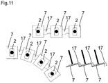
Figur 11- eine Leiterplatte mit flexiblen Leiterplattenabschnitten.
- FIG. 1
- a sensor system with optoelectronic distance sensor modules for monitoring a hazardous area with a spatial protective field;
- FIG. 2
- a sensor system with a cubic or square protective field;
- FIG. 3
- a sensor system with a rectangular protective field;
- FIG. 4 and FIG. 5
- a sensor system with a truncated pyramidal protective field;
- FIG. 6 and FIG. 7
- a sensor system with a frustoconical protective field;
- FIG. 8
- a sensor system with a cylindrical or circular cylindrical protective field;
- FIG. 9
- a sensor system with a printed circuit board;
- FIG. 10
- an enlarged section of the printed circuit board with distance sensor modules;
- FIG. 11
- a printed circuit board with flexible printed circuit board sections.
In den nachfolgenden Figuren sind identische Teile mit identischen Bezugszeichen versehen.In the following figures, identical parts are provided with identical reference numerals.
Das Sensorsystem 1 dient zum sicheren Überwachen des Gefahrenbereich 3 bzw. eines Überwachungsbereichs des bewegbaren Maschinenteils 4.The
Die Distanzsensormodule 2 sind entlang der Leiterplatte 7 beabstandet zueinander angeordnet, wobei die Detektionsstrahlen 9 der Distanzsensormodule 2 ein flächiges und räumliches Schutzfeld 10 bilden.The
Gemäß
Beispielsweise sind die Distanzsensormodule 2 Lichtlaufzeitsensoren mit einem Lichtsender und einem Lichtempfänger.For example, the
Zur Erzeugung eines quasi geschlossenen Schutzmantels bzw. räumlichen Schutzfeldes 10 aus den Distanzsensormodulen 2 ist eine verschiedene Anzahl der Distanzsensormodule 2 vorgesehen: Es kann beispielsweise die Sensoranzahl angepasst werden an die Erfordernisse einer bestimmten Anwendung. Je mehr Distanzsensormodule 2 angeordnet werden, desto dichter liegen die optischen Achsen 8 der Distanzsensoren 2 nebeneinander, wodurch das Schutzfeld 10 eine höhere Auflösung aufweist.For generating a quasi-closed protective jacket or spatial
Optional sind vor den Distanzsensormodulen 2 noch Vorsatzoptiken oder Optikmodule angeordnet. Jedoch können die Optikmodule auch in den Distanzsensormodulen 2 integriert sein.Optionally, additional optics or optical modules are arranged in front of the
Durch die hohe Anzahl an Distanzsensormodulen 2 kann eine entsprechend hohe räumliche Auflösung erreicht werden. Hierdurch können auch eine Vielzahl von Schutzfeldern 10 und eine Vielzahl von Schutzebenen angeordnet werden. Zudem werden Lücken oder Totbereiche zwischen den Distanzsensormodulen 2 klein gehalten.Due to the large number of
In Weiterbildung der Erfindung bilden die optischen Achsen 8 der Detektionsstrahlen 9 der Distanzsensormodule 2 ein zylindrisches 11, insbesondere kreiszylindrisches oder ringzylindrisches Schutzfeld 10.In a development of the invention, the
Gemäß
Gemäß
Gemäß
Gemäß
Die Steuer- und Auswerteeinheit 15 ist beispielsweise einkanalig mit Testung, zweikanalig redundant oder zweikanalig diversitär aufgebaut. Das Sensorsystem 1 gemäß
Die Steuer- und Auswerteeinheit 15 erkennt Schutzfeldverletzungen und kann ein sicherheitsgerichtetes Abschaltsignal ausgeben, um eine gefahrbringende Bewegung des Teils zu stoppen bzw. das Teil abzubremsen. Das kann z. B. über sichere Schaltsignale, z.B. OSSD-Signale (Output Safety Switching Device-Signale) oder sichere Distanzdaten, Abstandsdaten bzw. sichere Ortsdaten des Eingriffsereignisses realisiert werden.The control and
Die mehreren Distanzsensormodule 2 sind mit der Steuer- und Auswerteeinheit 15 zur Auswertung der Distanzsensormodule 2 verbunden. An diese Steuer- und Auswerteeinheit 15 sind alle Distanzsensormodule 2 bzw. Sensorchips direkt auf der Platine bzw. Leiterplatte 7 angeschlossen und werden von dieser parametriert, angesteuert und ausgelesen.The plurality of
Die Steuer- und Auswerteeinheit 15 ist wiederum über eine einzige Schnittstelle mit einer Robotersteuerung bzw. der übergeordneten Prozesssteuerung oder dem Netzwerk der Gesamtproduktion verbunden. Die Schnittstelle kann hierbei z. B. eine Feldbus- oder Funkverbindung sein. Im Falle einer Kabelverbindung kann hier ein hochflexibles Kabel verwendet werden, das sich besonders gut mit den beweglichen Gliedmaßen des Roboters kombiniert. Über diese Schnittstelle können schließlich alle Daten der angeschlossenen Sensoren auf der Platine abgerufen werden, sowie das Gesamtsystem mit dem Sensorsystem 1 von außen parametriert werden.The control and
Die Steuer- und Auswerteeinheit 15 kann auch an die Positionsdaten der Robotersteuerung angebunden werden, um einen entsprechenden Abgleich mit den Positionsdaten durchzuführen.The control and
Die Steuer- und Auswerteeinheit 15 kann zusätzliche Schnittstellen aufweisen, z. B. IO-Link, um weitere Sensoren zu Automatisierungszwecken in die Applikation einzubinden. Die Steuer- und Auswerteeinheit 15 dient hierbei auch als allgemeiner Sensorhub.The control and
Das integrierte Kameramodul 16 kann auch einfachere Vision-Anwendungen als Automatisierungsfunktion, wie beispielsweise Teile finden oder Roboter Guidance ggf. über ein integriertes Kundenprogramm konfigurierbar, bereitstellen.The
Gemäß
Mit dem Kameramodul 16 kann eine Szene visuell aus Sicht des Sensorsystems 1 betrachtet werden. Wird ein Kameramodul 16 ohne IR-Sperrfilter verbaut, ist beispielsweise auch die Lage der Sendespots der einzelnen Sensormodule sichtbar. Alternativ kann ein Kameramodul 16 mit RGB-IR Filterpattern verwendet werden, um Farb- und IR-Bild darzustellen.With the
Gemäß
Die flexiblen Leiterplatten 17 verbinden mechanisch und elektronisch die einzelnen Leiterplatten 7. Die flexiblen Leiterplatten 17 können dabei einstückig mit den starren Leiterplatten 7 verbunden sein. Durch die Verwendung von flexiblen Leiterplatten 17 können nahezu beliebige Konturen des Schutzfeldes 10 erzeugt werden, indem sie an einer entsprechenden mechanischen Aufnahme fixiert werden. Weiter ist eine variable, d. h. eine veränderliche Ausrichtung der Distanzsensormodule 2 möglich.The flexible printed
Gemäß einer nicht dargestellten Ausführungsform sind auf der Leiterplatte Beschleunigungs- und/oder Gyrosensoren angeordnet. Hierdurch kann die Lage des Sensorsystems im Raum erfasst werden. Dabei wird eine Kombinationen verschiedener Sensortechnologien auf einer Platine genutzt, um robuster gegenüber äußeren Einflüssen zu sein.According to an embodiment, not shown, acceleration and / or gyro sensors are arranged on the circuit board. As a result, the position of the sensor system can be detected in space. It uses a combination of different sensor technologies on one board to be more robust to external influences.
- 1 Sensorsystem1 sensor system
- 2 optoelektronische Distanzsensormodule2 opto-electronic distance sensor modules
- 3 Gefahrenbereich3 danger area
- 4 bewegbares Maschinenteil4 movable machine part
- 5 Schutzbereich5 protection area
- 6 Werkzeug6 tool
- 7 Leiterplatte7 circuit board
- 8 optische Achsen8 optical axes
- 9 Detektionsstrahlen9 detection beams
- 10 räumliches Schutzfeld10 spatial protective field
- 11 zylindrisches Schutzfeld11 cylindrical protective field
- 12 rechteckiges Schutzfeld12 rectangular protective field
- 13 kegelstumpfförmiges Schutzfeld13 frustoconical protective field
- 15 Steuer- und Auswerteeinheit15 control and evaluation unit
- 16 Kameramodul16 camera module
- 17 flexible Leiterplatten17 flexible printed circuit boards
Claims (8)
dadurch gekennzeichnet, dass
die optoelektronischen Distanzsensormodule (2) auf mindestens einer Leiterplatte (7) an dem bewegbaren Maschinenteil (4) angeordnet sind,
wobei eine Vielzahl von Distanzsensormodulen (2) angeordnet ist, wobei die optischen Achsen (8) der Detektionsstrahlen (9) der Distanzsensormodule (2) ein räumliches Schutzfeld (10) bilden.Sensor system (1) with optoelectronic distance sensor modules (2) for monitoring a danger zone (3) on a movable machine part (4) with at least one protective area (5), wherein on the movable machine part (4) a tool (6) and / or a workpiece is arranged
characterized in that
the optoelectronic distance sensor modules (2) are arranged on at least one printed circuit board (7) on the movable machine part (4),
wherein a plurality of distance sensor modules (2) is arranged, wherein the optical axes (8) of the detection beams (9) of the distance sensor modules (2) form a spatial protective field (10).
Applications Claiming Priority (1)
| Application Number | Priority Date | Filing Date | Title |
|---|---|---|---|
| DE102018113362.6A DE102018113362B4 (en) | 2018-06-05 | 2018-06-05 | Sensor system with optoelectronic distance sensor modules |
Publications (1)
| Publication Number | Publication Date |
|---|---|
| EP3578868A1 true EP3578868A1 (en) | 2019-12-11 |
Family
ID=66483956
Family Applications (1)
| Application Number | Title | Priority Date | Filing Date |
|---|---|---|---|
| EP19173872.3A Withdrawn EP3578868A1 (en) | 2018-06-05 | 2019-05-10 | Sensor system with optoelectronic distance sensor modules |
Country Status (2)
| Country | Link |
|---|---|
| EP (1) | EP3578868A1 (en) |
| DE (1) | DE102018113362B4 (en) |
Families Citing this family (1)
| Publication number | Priority date | Publication date | Assignee | Title |
|---|---|---|---|---|
| DE102020127670B4 (en) | 2020-10-21 | 2022-06-30 | Sick Ag | Securing a moving machine part |
Citations (4)
| Publication number | Priority date | Publication date | Assignee | Title |
|---|---|---|---|---|
| DE102008063081A1 (en) * | 2008-12-24 | 2010-08-05 | Gottfried Wilhelm Leibniz Universität Hannover | Securing device and method for operating a multi-unit machine |
| US20170030708A1 (en) * | 2015-07-31 | 2017-02-02 | Sick Ag | Distance Sensor |
| DE102017105999B3 (en) * | 2017-03-21 | 2018-03-01 | Sick Ag | Sensor system for a multi-unit robot |
| DE202017100522U1 (en) * | 2017-01-31 | 2018-05-03 | Sick Ag | monitoring device |
Family Cites Families (6)
| Publication number | Priority date | Publication date | Assignee | Title |
|---|---|---|---|---|
| DE202011000608U1 (en) * | 2011-03-17 | 2012-06-18 | Sick Ag | Mounting profile for a light curtain housing and light grid |
| DE202013104860U1 (en) * | 2013-10-30 | 2015-02-02 | Daimler Ag | working device |
| DE102015113336B4 (en) * | 2015-08-13 | 2017-10-05 | Karl Leibinger Medizintechnik Gmbh & Co. Kg | Handle device for a surgical light with sensors and surgical light |
| DE102015121840A1 (en) * | 2015-12-15 | 2017-06-22 | Sick Ag | Optoelectronic sensor and method for detecting an object |
| DE102016114835A1 (en) * | 2016-08-10 | 2018-02-15 | Joanneum Research Forschungsgesellschaft Mbh | robotic device |
| DE102017202004A1 (en) * | 2017-02-08 | 2018-08-09 | Thyssenkrupp Ag | Device for securing a machine-controlled handling device and method |
-
2018
- 2018-06-05 DE DE102018113362.6A patent/DE102018113362B4/en active Active
-
2019
- 2019-05-10 EP EP19173872.3A patent/EP3578868A1/en not_active Withdrawn
Patent Citations (5)
| Publication number | Priority date | Publication date | Assignee | Title |
|---|---|---|---|---|
| DE102008063081A1 (en) * | 2008-12-24 | 2010-08-05 | Gottfried Wilhelm Leibniz Universität Hannover | Securing device and method for operating a multi-unit machine |
| US20170030708A1 (en) * | 2015-07-31 | 2017-02-02 | Sick Ag | Distance Sensor |
| DE102015112656A1 (en) | 2015-07-31 | 2017-02-02 | Sick Ag | Distance sensor |
| DE202017100522U1 (en) * | 2017-01-31 | 2018-05-03 | Sick Ag | monitoring device |
| DE102017105999B3 (en) * | 2017-03-21 | 2018-03-01 | Sick Ag | Sensor system for a multi-unit robot |
Also Published As
| Publication number | Publication date |
|---|---|
| DE102018113362A1 (en) | 2019-12-05 |
| DE102018113362B4 (en) | 2021-07-15 |
Similar Documents
| Publication | Publication Date | Title |
|---|---|---|
| EP3136127B1 (en) | Distance sensor and method with a distance sensor | |
| EP2083209B1 (en) | Security system for contactless measurement of paths and/or speeds | |
| EP2386876B1 (en) | Optoelectronic safety sensor for measuring distance and method for monitoring a surveillance area | |
| EP3203263B1 (en) | Optoelectronic sensor and method for detecting objects | |
| EP2827173B1 (en) | Optoelectronic sensor and method for detecting objects | |
| EP2937715B1 (en) | Optoelectronic sensor and method for detecting measurement information from a surveillance area | |
| DE102015223710A1 (en) | Area monitoring sensor | |
| DE102010007520B3 (en) | Safety control with a large number of connections for sensors | |
| EP3517999B1 (en) | Optoelectronic sensor and method for detecting objects | |
| DE102019110882A1 (en) | Securing a moving machine part | |
| DE102017111886B3 (en) | Determine the movement of a machine to be protected | |
| EP3217195B1 (en) | Optical sensor | |
| DE10026711B4 (en) | Position monitoring device and method | |
| EP3578868A1 (en) | Sensor system with optoelectronic distance sensor modules | |
| EP3418846A1 (en) | Device for safety control of a machine | |
| EP3625585B1 (en) | Simulation device for a motor vehicle monitoring system | |
| EP3578867B1 (en) | Sensor system with optoelectronic distance sensors | |
| EP3527332A1 (en) | Secure sensor device and method for securing a mobile machine | |
| EP1959271B1 (en) | Opto-electronic sensor assembly and method for testing the functionality and/or adjusting an opto-electronic sensor assembly | |
| DE202017103611U1 (en) | Device for safety control of a machine | |
| DE102017119283B4 (en) | Sensor system | |
| DE102017103791B4 (en) | Optoelectronic sensor and method for detecting objects | |
| EP3578324A1 (en) | Sensor system with optoelectronic distance sensors | |
| DE102018102402A1 (en) | triangulation | |
| EP4279792B1 (en) | Light curtain |
Legal Events
| Date | Code | Title | Description |
|---|---|---|---|
| PUAI | Public reference made under article 153(3) epc to a published international application that has entered the european phase |
Free format text: ORIGINAL CODE: 0009012 |
|
| AK | Designated contracting states |
Kind code of ref document: A1 Designated state(s): AL AT BE BG CH CY CZ DE DK EE ES FI FR GB GR HR HU IE IS IT LI LT LU LV MC MK MT NL NO PL PT RO RS SE SI SK SM TR |
|
| AX | Request for extension of the european patent |
Extension state: BA ME |
|
| RAP1 | Party data changed (applicant data changed or rights of an application transferred) |
Owner name: SICK AG |
|
| STAA | Information on the status of an ep patent application or granted ep patent |
Free format text: STATUS: THE APPLICATION IS DEEMED TO BE WITHDRAWN |
|
| 18D | Application deemed to be withdrawn |
Effective date: 20200613 |