EP3578804A1 - Spark plug electrode wear rate determination for a spark-ignited engine - Google Patents
Spark plug electrode wear rate determination for a spark-ignited engine Download PDFInfo
- Publication number
- EP3578804A1 EP3578804A1 EP18176511.6A EP18176511A EP3578804A1 EP 3578804 A1 EP3578804 A1 EP 3578804A1 EP 18176511 A EP18176511 A EP 18176511A EP 3578804 A1 EP3578804 A1 EP 3578804A1
- Authority
- EP
- European Patent Office
- Prior art keywords
- spark plug
- ignition
- risetime
- fuel
- internal combustion
- Prior art date
- Legal status (The legal status is an assumption and is not a legal conclusion. Google has not performed a legal analysis and makes no representation as to the accuracy of the status listed.)
- Granted
Links
Images


Classifications
-
- F—MECHANICAL ENGINEERING; LIGHTING; HEATING; WEAPONS; BLASTING
- F02—COMBUSTION ENGINES; HOT-GAS OR COMBUSTION-PRODUCT ENGINE PLANTS
- F02P—IGNITION, OTHER THAN COMPRESSION IGNITION, FOR INTERNAL-COMBUSTION ENGINES; TESTING OF IGNITION TIMING IN COMPRESSION-IGNITION ENGINES
- F02P17/00—Testing of ignition installations, e.g. in combination with adjusting; Testing of ignition timing in compression-ignition engines
- F02P17/12—Testing characteristics of the spark, ignition voltage or current
-
- F—MECHANICAL ENGINEERING; LIGHTING; HEATING; WEAPONS; BLASTING
- F02—COMBUSTION ENGINES; HOT-GAS OR COMBUSTION-PRODUCT ENGINE PLANTS
- F02P—IGNITION, OTHER THAN COMPRESSION IGNITION, FOR INTERNAL-COMBUSTION ENGINES; TESTING OF IGNITION TIMING IN COMPRESSION-IGNITION ENGINES
- F02P11/00—Safety means for electric spark ignition, not otherwise provided for
- F02P11/06—Indicating unsafe conditions
-
- F—MECHANICAL ENGINEERING; LIGHTING; HEATING; WEAPONS; BLASTING
- F02—COMBUSTION ENGINES; HOT-GAS OR COMBUSTION-PRODUCT ENGINE PLANTS
- F02P—IGNITION, OTHER THAN COMPRESSION IGNITION, FOR INTERNAL-COMBUSTION ENGINES; TESTING OF IGNITION TIMING IN COMPRESSION-IGNITION ENGINES
- F02P17/00—Testing of ignition installations, e.g. in combination with adjusting; Testing of ignition timing in compression-ignition engines
- F02P17/10—Measuring dwell or antidwell time
-
- F—MECHANICAL ENGINEERING; LIGHTING; HEATING; WEAPONS; BLASTING
- F02—COMBUSTION ENGINES; HOT-GAS OR COMBUSTION-PRODUCT ENGINE PLANTS
- F02P—IGNITION, OTHER THAN COMPRESSION IGNITION, FOR INTERNAL-COMBUSTION ENGINES; TESTING OF IGNITION TIMING IN COMPRESSION-IGNITION ENGINES
- F02P3/00—Other installations
- F02P3/02—Other installations having inductive energy storage, e.g. arrangements of induction coils
- F02P3/04—Layout of circuits
- F02P3/05—Layout of circuits for control of the magnitude of the current in the ignition coil
- F02P3/051—Opening or closing the primary coil circuit with semiconductor devices
- F02P3/053—Opening or closing the primary coil circuit with semiconductor devices using digital techniques
-
- H—ELECTRICITY
- H01—ELECTRIC ELEMENTS
- H01T—SPARK GAPS; OVERVOLTAGE ARRESTERS USING SPARK GAPS; SPARKING PLUGS; CORONA DEVICES; GENERATING IONS TO BE INTRODUCED INTO NON-ENCLOSED GASES
- H01T13/00—Sparking plugs
- H01T13/58—Testing
-
- H—ELECTRICITY
- H01—ELECTRIC ELEMENTS
- H01T—SPARK GAPS; OVERVOLTAGE ARRESTERS USING SPARK GAPS; SPARKING PLUGS; CORONA DEVICES; GENERATING IONS TO BE INTRODUCED INTO NON-ENCLOSED GASES
- H01T13/00—Sparking plugs
- H01T13/58—Testing
- H01T13/60—Testing of electrical properties
-
- F—MECHANICAL ENGINEERING; LIGHTING; HEATING; WEAPONS; BLASTING
- F02—COMBUSTION ENGINES; HOT-GAS OR COMBUSTION-PRODUCT ENGINE PLANTS
- F02D—CONTROLLING COMBUSTION ENGINES
- F02D2200/00—Input parameters for engine control
- F02D2200/02—Input parameters for engine control the parameters being related to the engine
- F02D2200/04—Engine intake system parameters
- F02D2200/0406—Intake manifold pressure
-
- F—MECHANICAL ENGINEERING; LIGHTING; HEATING; WEAPONS; BLASTING
- F02—COMBUSTION ENGINES; HOT-GAS OR COMBUSTION-PRODUCT ENGINE PLANTS
- F02D—CONTROLLING COMBUSTION ENGINES
- F02D2200/00—Input parameters for engine control
- F02D2200/02—Input parameters for engine control the parameters being related to the engine
- F02D2200/04—Engine intake system parameters
- F02D2200/0414—Air temperature
-
- F—MECHANICAL ENGINEERING; LIGHTING; HEATING; WEAPONS; BLASTING
- F02—COMBUSTION ENGINES; HOT-GAS OR COMBUSTION-PRODUCT ENGINE PLANTS
- F02D—CONTROLLING COMBUSTION ENGINES
- F02D2200/00—Input parameters for engine control
- F02D2200/02—Input parameters for engine control the parameters being related to the engine
- F02D2200/10—Parameters related to the engine output, e.g. engine torque or engine speed
- F02D2200/1015—Engines misfires
-
- F—MECHANICAL ENGINEERING; LIGHTING; HEATING; WEAPONS; BLASTING
- F02—COMBUSTION ENGINES; HOT-GAS OR COMBUSTION-PRODUCT ENGINE PLANTS
- F02D—CONTROLLING COMBUSTION ENGINES
- F02D35/00—Controlling engines, dependent on conditions exterior or interior to engines, not otherwise provided for
- F02D35/02—Controlling engines, dependent on conditions exterior or interior to engines, not otherwise provided for on interior conditions
- F02D35/027—Controlling engines, dependent on conditions exterior or interior to engines, not otherwise provided for on interior conditions using knock sensors
-
- F—MECHANICAL ENGINEERING; LIGHTING; HEATING; WEAPONS; BLASTING
- F02—COMBUSTION ENGINES; HOT-GAS OR COMBUSTION-PRODUCT ENGINE PLANTS
- F02P—IGNITION, OTHER THAN COMPRESSION IGNITION, FOR INTERNAL-COMBUSTION ENGINES; TESTING OF IGNITION TIMING IN COMPRESSION-IGNITION ENGINES
- F02P13/00—Sparking plugs structurally combined with other parts of internal-combustion engines
-
- F—MECHANICAL ENGINEERING; LIGHTING; HEATING; WEAPONS; BLASTING
- F02—COMBUSTION ENGINES; HOT-GAS OR COMBUSTION-PRODUCT ENGINE PLANTS
- F02P—IGNITION, OTHER THAN COMPRESSION IGNITION, FOR INTERNAL-COMBUSTION ENGINES; TESTING OF IGNITION TIMING IN COMPRESSION-IGNITION ENGINES
- F02P17/00—Testing of ignition installations, e.g. in combination with adjusting; Testing of ignition timing in compression-ignition engines
- F02P17/12—Testing characteristics of the spark, ignition voltage or current
- F02P2017/121—Testing characteristics of the spark, ignition voltage or current by measuring spark voltage
-
- H—ELECTRICITY
- H01—ELECTRIC ELEMENTS
- H01T—SPARK GAPS; OVERVOLTAGE ARRESTERS USING SPARK GAPS; SPARKING PLUGS; CORONA DEVICES; GENERATING IONS TO BE INTRODUCED INTO NON-ENCLOSED GASES
- H01T13/00—Sparking plugs
- H01T13/54—Sparking plugs having electrodes arranged in a partly-enclosed ignition chamber
Definitions
- the present disclosure generally relates to an ignition system such as in an internal combustion engine. More particularly, the present disclosure relates to a method for determining the wear rate of a spark plug electrode of the ignition system and an ignition system for an internal combustion engine configured to perform the method for determining the wear rate of a spark plug electrode.
- a spark plug for generating a spark arc based on external energy supply is required.
- the spark plug is provided with two electrodes between which the spark arc is to be generated.
- a definite minimum energy is required to ignite the fuel-air-mixture inside the cylinder. This definite minimum energy generally leads to high electrode temperatures and, as a consequence, to an erosion of the electrodes. Electrode erosion could be measured in form of wear and could be used for monitoring the state of a spark plug and determining the wear of a spark plug, for instance, in order to decide whether the spark plug has to be replaced or not.
- An exemplary apparatus and method for determining the wear rate of a spark plug of an internal combustion engine by use of wear determination means is disclosed in EP 1 835 172 A2 .
- the wear determination means determine a current wear of a spark plug based on operating conditions of the internal combustion engine and add this current wear to a total wear state of the spark plug.
- the present disclosure is directed, at least in part, to improving or overcoming one or more aspects of prior systems.
- a method for determining the wear rate of a spark plug electrode of an ignition system including a spark plug of an internal combustion engine comprises determining a risetime number depending on or indicating the time required for raising an ignition energy (energy in form of current) which is supplied to an ignition coil of the spark plug from an inactive level to a predetermined level and determining an operating condition indicator configured to indicate or be dependent on an operating condition of the ignition system.
- the method further comprises determining a spark plug state indicator as a value based on the determined risetime number and the determined operating condition indicator, wherein at least two for example successive spark plug state indicators are stored in a memory at predetermined time intervals, and determining a wear rate of the spark plug based on a difference of the actual (a first) spark plug state indicator indicating the spark plug electrode state at a first time instance and a second (for instance, the previous) spark plug state indicator indicating the spark plug electrode state at a second time instance, wherein the first time instance and the second time instance are separated by the predetermined time interval.
- an ignition system for an internal combustion engine comprises at least one spark plug, an ignition coil for the at least one spark plug and a control unit electronically connected to the ignition coil and configured to perform the method according to the above aspect.
- an internal combustion engine specifically an internal combustion engine working on gaseous fuel.
- the internal combustion engine comprises a plurality of cylinders each defining a combustion chamber therein for igniting fuel, a plurality of injectors each one being assigned to a respective cylinder for injecting fuel, and an ignition system according to the above aspect.
- a computer program comprises computer-executable instructions which, when run on a computer, cause the computer to perform the steps of the method according to the above aspect.
- the present disclosure is based in part on the realization that the performance and the efficiency of an ignition system of an internal combustion engine operating on gaseous fuel depends inter alia on the state of the spark plug electrodes mounted in the ignition system of the internal combustion engine. Spark plug electrodes are subjected to wear due to high temperatures at the spark plug electrodes in the event of igniting a fuel-air-mixture inside a cylinder of the internal combustion engine. The high temperatures result in an erosion of the electrodes what again results in a changed, usually increased, distance between the electrodes. The increasing distance between the electrodes requires higher breakdown voltages, stronger electric fields and hence more ignition energy for igniting the fuel-air-mixture inside the cylinder.
- a spark plug with a high wear rate requires more ignition energy and, thus, a higher secondary voltage for igniting the fuel-air-mixture inside a cylinder than a spark plug with no or a low wear rate. That is, the higher the wear rate of a spark plug, the worse are the ignition conditions and, thus, the higher is the risk for abnormal combustion and sub-optimal engine operation.
- the wear of the spark plug electrodes is that excessive that the available energy does not suffice for igniting the fuel-air-mixture in the cylinder. Consequently, the wear rate of a spark plug electrode has to be monitored in order to determine timely that a spark plug has to be replaced and, thus, to assure optimum engine performance.
- An ignition system generally comprises a control unit, an ignition coil and a spark plug.
- the spark plug is generally provided with two electrodes.
- the method allows the determination of wear of a spark plug electrode in a defined time period.
- the wear of a spark plug electrode in a defined time period is called a spark plug wear rate.
- the method frequently determines at predetermined time intervals the state of a spark plug and, thus, determines in real-time how much the spark plug is subjected to wear until now. Afterwards, the method determines based on a difference of two spark plug state indicators how much the electrodes have been subjected to wear in this time interval.
- the spark plug state indicators may correspond to two subsequent spark plug state indicators, but may also correspond to spark plug state indicators which are not directly successive to each other.
- the first spark plug state indicator may be compared with the third spark plug state indicator or the second spark plug state indicator may be compared to the fourth spark plug state indicator and so on.
- the result of this determination corresponds to the wear rate per time unit and may allow the prediction of the lifespan of the concerned spark plug.
- a predetermined number of spark plug state indicators at least two for example successive spark plug state indicators have to be stored in a memory (preferably a nonvolatile memory). It is preferred to store the last five spark plug state indicators which have been determined.
- the time interval in which the spark plug electrode state is determined corresponds to a trigger time interval and may be chosen dependent on how accurate the spark plug has to be monitored.
- the term "trigger" means the event when the state of the spark plug is monitored (i.e., the time span).
- the accuracy of monitoring the spark plug may depend on the kind of internal combustion engine (stationary engine for producing electrical energy, internal combustion engine of a vehicle, etc.), the operating condition of the internal combustion engine (idle running, slow running, fast running, etc.), manufacturer's instructions, and the like, but stays preferably constant during an entire spark plug electrode state determination cycle.
- a spark plug electrode state determination cycle extends from mounting to exchanging of a spark plug.
- spark plug electrode state determination cycle may also depend on different operating conditions of the internal combustion engine.
- the spark plug electrode state is determined and stored in the memory periodically and, thus, at regular intervals like intervals between 1 and 600 minutes, specifically between 30 and 90 minutes, for example between 40 and 90 minutes.
- the determination of the spark plug state indicator may be based on a non-dimensional risetime number and an operating condition indicator which are stored in a 3D look-up map in form of a fraction value.
- the map may be calibrated based on fundamental investigation, accelerated testing and actual behavior of spark plugs over the time. Further, the calibration of the map may vary depending on the engine type and application and/or the ignition system type.
- the risetime number is the time which is required to raise the primary current supplied to the ignition coil from an inactive level to a predefined level.
- the risetime number is contained in an electronic control module (ECM) as a cylinder individual cyclic feedback for each ignition cycle.
- ECM electronice control module
- the risetime number may be a non-dimensional number which is preferably based on a statistical mean value and a standard deviation (variance), in order to combine the effect of both a mean value and a standard deviation.
- Non-dimensional numbers generally have the advantage that they allow an assessment of a situation in an easy and quick manner.
- an operating condition indicator allows an indication of the operating condition of the internal combustion engine.
- various conditions of the internal combustion engine may be considered, such as the operating load, the operating temperatures, the operating pressures, intake air conditions, etc.
- the operating condition indicator corresponds to the density of the fuel-air-mixture in the cylinder at the time of ignition and, thus, corresponds to the mixture density at the time of ignition.
- This density of the fuel-air mixture may preferably be calculated based on the initial density of the fuel-air-mixture and the ignition angle, i.e., the crank shaft angle at which the ignition of the fuel-air-mixture takes place.
- the initial density of the fuel-air-mixture may preferably be calculated based on the pressure and the temperature at the intake manifold which are both measured by use of suitable sensors. However, it is noted that the initial density may also be calculated based on other operating conditions of the internal combustion engine (e.g. by means of a mass flow sensor). The ignition angle may be determined in real-time or based on a look-up table.
- Fig. 1 depicts a piston 2 arranged in a cylinder 4 of a portion of an internal combustion engine 1 (not shown in further detail).
- the cylinder 4 is covered by a cylinder head 6.
- the piston 2, the cylinder 4, and the cylinder head 6 together define a main combustion chamber 8 of the internal combustion engine 1.
- the piston 2 is reciprocating in the cylinder 4 to move between a top dead center (TDC) and a bottom dead center (BDC) during operation of the internal combustion engine 1.
- TDC top dead center
- BDC bottom dead center
- the internal combustion engine 1 is considered as a four-stroke stationary or marine internal combustion engine operating at least partly on gaseous fuel such as a gaseous fuel engine or a dual fuel engine.
- gaseous fuel such as a gaseous fuel engine or a dual fuel engine.
- the internal combustion engine may be any type of engine (turbine, gas, diesel, natural gas, propane, two-stroke, etc.) that would utilize the spark plug diagnostics as disclosed herein.
- the internal combustion engine may be of any size, with any number of cylinders, and in any configuration (V-type, in-line, radial, etc.).
- the internal combustion engine may be used to power any machine or other device, including locomotive applications, on-highway trucks or vehicles, off-highway trucks or machines, earth moving equipment, generators, aerospace applications, marine applications, pumps, stationary equipment, or other engine powered applications.
- the internal combustion engine 1 may use a pre-mixed fuel air mixture supplied to the cylinder 4 via inlet channels, or may directly inject a fuel into the cylinder 4.
- the cylinder head 6 includes at least one inlet valve 10, for example a poppet valve.
- the inlet valve 10 is accommodated in an inlet channel 12 opening in a piston sided face 14 of the cylinder head 6 for supplying a mixture of gaseous fuel and air into the main combustion chamber 8.
- at least one outlet valve 16 is accommodated in an outlet channel 18 of the cylinder head 6 to guide exhaust gas out of the main combustion chamber 8.
- the cylinder head 6 further comprises a pre-chamber assembly 20
- a plurality of flow transfer channels 22 fluidly connect the main combustion chamber 8 with an interior of the pre-chamber assembly 20 (not visible in Fig. 1 ).
- the pre-chamber assembly 20 is installed in the cylinder head 6 via a mounting body 24 as shown in Fig. 1 .
- the pre-chamber assembly 20 may be installed in the cylinder head 6 in any other fashion.
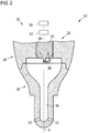
- the pre-chamber assembly 20 is shown in a schematic sectional view.
- the pre-chamber assembly 20 includes a first pre-chamber body 26, a second pre-chamber body 28, and a spark plug 30.
- the pre-chamber assembly 20 may further comprise a fuel supply device for enriching a pre-chamber 34 of the pre-chamber assembly 20.
- the first pre-chamber body 26 and the second pre-chamber body 28 are connected to one another.
- the spark plug 30 is accommodated in the second pre-chamber body 28
- the first pre-chamber body 26 includes and defines the pre-chamber 34, a riser channel 38 and the flow transfer channels 22.
- the flow transfer channels 22 fluidly connect an interior of the pre-chamber body 26 (the pre-chamber 34 and the riser channel 38) and the main combustion chamber 8 ( Fig. 1 ).
- the pre-chamber 34 extends along a longitudinal axis A of the first pre-chamber body 26, is funnel-shaped, and tapers in direction to the riser channel 38.
- the pre-chamber 34 may have any other shape such as a cylindrical shape, pyramidal shape, conical shape, and combinations thereof.
- the pre-chamber 34 may have a volume within a range between 0,1 % and 10 % of the compression volume of the cylinder 4 (see Fig. 1 ).
- the spark plug 30 is installed in the pre-chamber assembly 20 so that the spark plug 30 is operably coupled to the pre-chamber 34. Particularly, electrodes of the spark plug 30 may reach into the pre-chamber 34 so that a spark between the electrodes ignites a mixture in the pre-chamber 34.
- a pre-chamber 34 may be omitted and/or the spark plug 30 may reach into the main combustion chamber 8 of the internal combustion engine 1.
- the spark plug 30 may be a main combustion chamber spark plug, a pre-chamber spark plug, a chamber plug (including an integrated chamber for shielding the electrodes), a ring-type spark plug, a j-type spark plug, etc.
- An ignition system 56 includes a control unit 50, an ignition coil 54, and the spark plug 30.
- the ignition coil 52 may be integrated into the spark plug 30.
- the control unit 50 is electronically connected to the ignition coil 54 which in turn is electronically connected to the spark plug 30.
- the control unit 50 is configured to actuate the ignition system 56.
- the control unit 50 may be further configured to adapt an operation of the internal combustion engine 1, for example adapting an engine speed, adapting a charge air pressure, adapting a fuel supply, adapting a timing of a fuel supply and an ignition, etc.
- the control unit 50 and/or the ignition system 56 may be a part of a control system 52 further including the electrical connections to the components.
- the control unit 50 may be a single microprocessor or multiple microprocessors that include means for controlling, among others, an operation of various components of the internal combustion engine 1.
- the control unit 50 may be a general engine control unit (ECU) capable of controlling the internal combustion engine 1 and/or its associated components or a specific engine control unit dedicated to the ignition system 56.
- the control unit 50 may include all components required to run an application such as, for example, a memory, a secondary storage device, and a processor such as a central processing unit or any other means known in the art for controlling the internal combustion engine 1 and its components.
- Various other known circuits may be associated with the control unit 50, including power supply circuitry, signal conditioning circuitry, communication circuitry and other appropriate circuitry.
- the control unit 50 may analyze and compare received and stored data and, based on instructions and data stored in memory or input by a user, determine whether action is required. For example, the control unit 50 may compare received values with target values stored in memory, and, based on the results of the comparison, transmit signals to one or more components to alter the operation status of the same.
- the control unit 50 may include any memory device known in the art for storing data relating to an operation of the internal combustion engine 1 and its components.
- the data may be stored in the form of one or more maps (mappings).
- Each of the maps may be in the form of tables, graphs and/or equations, and may include a compilation of data collected from lab and/or field operation or simulations of the internal combustion engine 1.
- the maps may be generated by performing instrumented tests on the operation of the internal combustion engine 1 under various operating conditions while varying parameters associated therewith or performing various measurements.
- the control unit 50 may reference these maps and control operation of one component in response to the desired operation of another component.
- the maps may contain data on the spark plug electrode state depending on a specific combination of an operation value of an electrical parameter of the spark plug 30 and operating conditions of the internal combustion engine 1.
- the control unit 50 is further configured to perform the method for determining the wear rate of the electrodes of the spark plug 30 of the ignition system 56 as disclosed herein, in particular, the method as described in the following with respect to Figs. 3 to 7 .
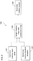
- Fig. 3 shows a process chart illustrating the first step 100 of determining the wear rate of the electrode of a spark plug 30 according to the present disclosure, namely the determining of a risetime number in step 140.
- the risetime number is determined based on a determination of a risetime mean value in step 110 and a determination of a risetime standard deviation (variance) in step 120.
- the risetime is the time which is required for raising the primary current supplied to the ignition coil 54 from an inactive, switched-off level to a predefined level and is measured in microseconds.
- the predefined level usually corresponds to the level which allows the breakdown of the magnetic field generated by the ignition coil, the generation of a high voltage impulse and a quick transition from glow discharge to arc discharge at the two spark plug electrodes.
- the risetime mean value corresponds to an average time which is required to raise the ignition coil current from an inactive level to a predefined level which is necessary to generate the high voltage impulse.
- the average time is determined over various ignition cycles by the electronic control module, i.e., over various cycles in which a fuel-air-mixture inside the cylinder is ignited.
- both the risetime mean value and the risetime standard deviation are weighted in a map, for example, a characteristic diagram.
- the risetime number may be determined based on the map. As both the risetime mean value and the risetime standard deviation are set in relation to each other, the rise time number has no dimension what simplifies the assessment of the rise time.
- Fig. 4 shows a process chart illustrating the second step 200 of determining the wear rate of the electrode of the spark plug 30 according to the present disclosure, namely determining an operating condition indicator in step 260.
- the operating condition indicator may correspond to density at ignition point ⁇ ip of the fuel-air-mixture at the ignition time and may be based on the calculation of an initial density ⁇ i of the fuel-air-mixture at step 230, i.e., the density of the fuel-air-mixture in intake manifold and the determination of the ignition angle at step 240, i.e., the angle of the crank shaft at which the ignition occurs, usually measured by a suitable sensor device.
- the calculation of the initial density ⁇ i in step 230 may be based on the pressure (step 210) and the temperature (step 220) of the fuel-air-mixture at the intake manifold.
- the initial density ⁇ i and the ignition angle are weighted in a map at step 250.
- Fig. 5 shows a process chart illustrating the third step 300 of determining the wear rate of the electrode of the spark plug 30 according to the present disclosure, namely determining the spark plug state.
- a spark plug state indicator SSI the already determined risetime number is taken from the ECM in step 310 and the already determined operating condition indicator is taken from ECM in step 320. Both the risetime number and the operating condition indicator are outputted in a 3D look-up map in step 330.
- FIG. 6 An exemplary 3D look-up map is shown in Fig. 6 .
- the risetime number is assigned to the axis of abscissae (X-axis) and the operating condition indicator ⁇ ip is assigned to the axis of ordinates (Y-axis).
- isolines indicate the same state of a spark plug and, thus, its electrodes, and correspond to a "spark plug common condition value".
- the spark plug common condition value corresponds to a number indicating the state of a spark plug electrode and is determined by calibration based on fundamental investigation, accelerated testing and/or actual behavior of spark plugs over time.
- the breakdown voltage and the risetime is a function of density in between the two electrodes of the sparkplug and the gap between two electrodes. For a given electrode gap the risetime would increase with increasing density.
- isolines represent a same state of electrode gap that represents the dependency of density inbetween the electrodes, i.e, the operating load for the engine.
- the mode of calibration may vary depending on the application or the ignition system type.
- a new spark plug may have a spark plug common condition value of 0.5, whereas a completely worn spark plug may have a spark plug common condition value of 1.0.
- the isoline denoting the new spark plug is situated leftmost and the isoline denoting the worn spark plug is situated rightmost in the 3D look-up map shown in Fig. 6 .
- the more the spark plug is worn the more it is positioned and displaced, respectively, to the left in the 3D look-up map of Fig. 6 .
- a new spark plug having a spark plug common condition value of 0.5 may have a low risetime number of around 45 if the ignition density ⁇ ip of the fuel-air-mixture is low, e.g., approximately 1.10 as may be in case of idle running of the internal combustion engine.
- a new spark plug having a spark plug common condition value of 0.5 may have a high risetime number of around 85 if the ignition density ⁇ ip of the fuel-air-mixture is high, e.g., approximately 5.50 as may be in case of high load operation of the internal combustion engine.
- a worn spark plug having a spark plug common condition value of 1.0 may have a high risetime number of around 105 if the ignition density ⁇ ip of the fuel-air-mixture is low, e.g., approximately 1.10 as may be in case of idle running of the internal combustion engine and may have a higher risetime number of around 185 if the ignition density ⁇ ip of the fuel-air-mixture is higher, e.g., approximately 2.50 as may be in case of normal load operation of the internal combustion engine.
- a spark plug with a completely worn electrode and, thus, a spark plug common condition value of 1.0 can no longer be used for high load operation of the internal combustion engine, because no spark arc may be generated with a spark plug having such worn electrodes.
- the spark plug state indicator SSI is determined in predetermined trigger time intervals in step 340, such as every 30 minutes. However, it is also appreciated that the spark plug state indicator SSI is determined every 60 minutes, 600 minutes, etc.
- a predetermined integral number of spark plug state indicators SSI is stored in a memory in step 350.
- the last five spark plug state indicators SSI are stored in the memory and the oldest spark plug state indicator SSI is replaced by a new spark plug state indicator SSI in form of a ring saving mechanism.
- the memory is preferably a nonvolatile memory.
- the wear rate of the monitored spark plug electrode is calculated in step 360 of Fig. 5 .
- the wear rate is calculated as a difference between the current spark plug state indicator SSI n+1 and the previous spark plug state indicator SSI n divided by the time period used as trigger time interval. In the following, the calculation of the wear rate is explained in detail.
- ⁇ SSI SSI n + 1 ⁇ SSI n
- the change of the spark plug state indicator ⁇ SSI is 0.005. If the trigger time interval is 60 minutes, i.e. the spark plug state indicator SSI is measured every hour, the wear rate WR is 0.005 per hour.
- the spark plug wear rate may be communicated to the ECM and may be used for further actions, such as condition monitoring, calibrating an engine control or the spark wave form.
- the spark plug wear rate may be used to determine when a particular spark plug has to be replaced and to indicate the upcoming spark plug replacement to a driver.
- the method and ignition system as disclosed herein are applicable in internal combustion engines for monitoring an ignition system and a state of the spark plug.
- the methods and control systems as disclosed herein may be applied in large internal combustion engines, in which combustion processes of the cylinders may be individually controlled so that cylinders having a spark plug with a reduced sparkability can be further operated under low load conditions to maintain an operation of the affected cylinder until the next maintenance.
- the method and ignition system as disclosed herein may further assist in pinpointing the reason for a misfire and/or an abnormal behavior of a spark plug.
Landscapes
- Engineering & Computer Science (AREA)
- Chemical & Material Sciences (AREA)
- Combustion & Propulsion (AREA)
- Mechanical Engineering (AREA)
- General Engineering & Computer Science (AREA)
- Ignition Installations For Internal Combustion Engines (AREA)
Abstract
Description
- The present disclosure generally relates to an ignition system such as in an internal combustion engine. More particularly, the present disclosure relates to a method for determining the wear rate of a spark plug electrode of the ignition system and an ignition system for an internal combustion engine configured to perform the method for determining the wear rate of a spark plug electrode.
- In order to initiate combustion of a compressed fuel-air-mixture in a cylinder of a reciprocating spark-ignition (SI) engine, in particular for engines operating on gaseous fuel, a spark plug for generating a spark arc based on external energy supply is required. In general, the spark plug is provided with two electrodes between which the spark arc is to be generated. Depending on the engine operating conditions, the state of an ignition coil and the state of the spark plug electrodes, a definite minimum energy is required to ignite the fuel-air-mixture inside the cylinder. This definite minimum energy generally leads to high electrode temperatures and, as a consequence, to an erosion of the electrodes. Electrode erosion could be measured in form of wear and could be used for monitoring the state of a spark plug and determining the wear of a spark plug, for instance, in order to decide whether the spark plug has to be replaced or not.
- An exemplary apparatus and method for determining the wear rate of a spark plug of an internal combustion engine by use of wear determination means is disclosed in
EP 1 835 172 A2 - The present disclosure is directed, at least in part, to improving or overcoming one or more aspects of prior systems.
- In one aspect, a method for determining the wear rate of a spark plug electrode of an ignition system including a spark plug of an internal combustion engine is disclosed. The method comprises determining a risetime number depending on or indicating the time required for raising an ignition energy (energy in form of current) which is supplied to an ignition coil of the spark plug from an inactive level to a predetermined level and determining an operating condition indicator configured to indicate or be dependent on an operating condition of the ignition system. The method further comprises determining a spark plug state indicator as a value based on the determined risetime number and the determined operating condition indicator, wherein at least two for example successive spark plug state indicators are stored in a memory at predetermined time intervals, and determining a wear rate of the spark plug based on a difference of the actual (a first) spark plug state indicator indicating the spark plug electrode state at a first time instance and a second (for instance, the previous) spark plug state indicator indicating the spark plug electrode state at a second time instance, wherein the first time instance and the second time instance are separated by the predetermined time interval.
- In another aspect, an ignition system for an internal combustion engine is disclosed. The ignition system comprises at least one spark plug, an ignition coil for the at least one spark plug and a control unit electronically connected to the ignition coil and configured to perform the method according to the above aspect.
- In yet another aspect, an internal combustion engine, specifically an internal combustion engine working on gaseous fuel, is disclosed. The internal combustion engine comprises a plurality of cylinders each defining a combustion chamber therein for igniting fuel, a plurality of injectors each one being assigned to a respective cylinder for injecting fuel, and an ignition system according to the above aspect.
- In yet another aspect, a computer program is disclosed. The computer-program comprises computer-executable instructions which, when run on a computer, cause the computer to perform the steps of the method according to the above aspect.
- Other features and aspects of this disclosure will be apparent from the following description and the accompanying drawings.
- The accompanying drawings, which are incorporated herein and constitute a part of the specification, illustrate exemplary embodiments of the disclosure and, together with the description, serve to explain the principles of the disclosure. In the drawings:
-
Fig. 1 shows a schematic cut view through a portion of an internal combustion engine that is equipped with a pre-chamber; -
Fig. 2 shows a schematic cut view through an exemplary pre-chamber assembly including a spark plug; -
Fig. 3 shows a process chart for determining of a risetime number according to the present disclosure; -
Fig. 4 shows a process chart for determining an operating condition indicator according to the present disclosure; -
Fig. 5 shows a process chart for determining a spark plug state indicator and a spark plug electrode wear rate according to the present disclosure; and -
Fig. 6 shows different spark plug electrode states in a 3D look-up map according to the present disclosure. - The following is a detailed description of exemplary embodiments of the present disclosure. The exemplary embodiments described therein and illustrated in the drawings are intended to teach the principles of the present disclosure, enabling those of ordinary skill in the art to implement and use the present disclosure in many different environments and for many different applications. Therefore, the exemplary embodiments are not intended to be, and should not be considered as, a limiting description of the scope of patent protection. Rather, the scope of patent protection shall be defined by the appended claims.
- The present disclosure is based in part on the realization that the performance and the efficiency of an ignition system of an internal combustion engine operating on gaseous fuel depends inter alia on the state of the spark plug electrodes mounted in the ignition system of the internal combustion engine. Spark plug electrodes are subjected to wear due to high temperatures at the spark plug electrodes in the event of igniting a fuel-air-mixture inside a cylinder of the internal combustion engine. The high temperatures result in an erosion of the electrodes what again results in a changed, usually increased, distance between the electrodes. The increasing distance between the electrodes requires higher breakdown voltages, stronger electric fields and hence more ignition energy for igniting the fuel-air-mixture inside the cylinder. In worst case, the distance between the electrodes is so that large that no spark arc is generated and, thus, the fuel-air-mixture inside the cylinder is not ignited. Accordingly, in general, a spark plug with a high wear rate requires more ignition energy and, thus, a higher secondary voltage for igniting the fuel-air-mixture inside a cylinder than a spark plug with no or a low wear rate. That is, the higher the wear rate of a spark plug, the worse are the ignition conditions and, thus, the higher is the risk for abnormal combustion and sub-optimal engine operation. In worst case, the wear of the spark plug electrodes is that excessive that the available energy does not suffice for igniting the fuel-air-mixture in the cylinder. Consequently, the wear rate of a spark plug electrode has to be monitored in order to determine timely that a spark plug has to be replaced and, thus, to assure optimum engine performance.
- The present disclosure suggests a method for determining the wear rate of a spark plug electrode of an ignition system. An ignition system generally comprises a control unit, an ignition coil and a spark plug. The spark plug is generally provided with two electrodes. The method allows the determination of wear of a spark plug electrode in a defined time period. The wear of a spark plug electrode in a defined time period is called a spark plug wear rate. To determine the spark plug electrode wear rate, the method frequently determines at predetermined time intervals the state of a spark plug and, thus, determines in real-time how much the spark plug is subjected to wear until now. Afterwards, the method determines based on a difference of two spark plug state indicators how much the electrodes have been subjected to wear in this time interval. The spark plug state indicators may correspond to two subsequent spark plug state indicators, but may also correspond to spark plug state indicators which are not directly successive to each other. For example, also the first spark plug state indicator may be compared with the third spark plug state indicator or the second spark plug state indicator may be compared to the fourth spark plug state indicator and so on. The result of this determination corresponds to the wear rate per time unit and may allow the prediction of the lifespan of the concerned spark plug. For determining the spark plug electrode wear rate, a predetermined number of spark plug state indicators, at least two for example successive spark plug state indicators have to be stored in a memory (preferably a nonvolatile memory). It is preferred to store the last five spark plug state indicators which have been determined.
- The time interval in which the spark plug electrode state is determined corresponds to a trigger time interval and may be chosen dependent on how accurate the spark plug has to be monitored. In the present disclosure, the term "trigger" means the event when the state of the spark plug is monitored (i.e., the time span). For instance, the accuracy of monitoring the spark plug may depend on the kind of internal combustion engine (stationary engine for producing electrical energy, internal combustion engine of a vehicle, etc.), the operating condition of the internal combustion engine (idle running, slow running, fast running, etc.), manufacturer's instructions, and the like, but stays preferably constant during an entire spark plug electrode state determination cycle. Preferably, a spark plug electrode state determination cycle extends from mounting to exchanging of a spark plug. However, a spark plug electrode state determination cycle may also depend on different operating conditions of the internal combustion engine. The spark plug electrode state is determined and stored in the memory periodically and, thus, at regular intervals like intervals between 1 and 600 minutes, specifically between 30 and 90 minutes, for example between 40 and 90 minutes.
- The determination of the spark plug state indicator may be based on a non-dimensional risetime number and an operating condition indicator which are stored in a 3D look-up map in form of a fraction value. The map may be calibrated based on fundamental investigation, accelerated testing and actual behavior of spark plugs over the time. Further, the calibration of the map may vary depending on the engine type and application and/or the ignition system type.
- The risetime number is the time which is required to raise the primary current supplied to the ignition coil from an inactive level to a predefined level. The risetime number is contained in an electronic control module (ECM) as a cylinder individual cyclic feedback for each ignition cycle. The risetime number may be a non-dimensional number which is preferably based on a statistical mean value and a standard deviation (variance), in order to combine the effect of both a mean value and a standard deviation. Non-dimensional numbers generally have the advantage that they allow an assessment of a situation in an easy and quick manner.
- The determination of an operating condition indicator allows an indication of the operating condition of the internal combustion engine. For determining the operating condition indicator various conditions of the internal combustion engine may be considered, such as the operating load, the operating temperatures, the operating pressures, intake air conditions, etc. Preferably, the operating condition indicator corresponds to the density of the fuel-air-mixture in the cylinder at the time of ignition and, thus, corresponds to the mixture density at the time of ignition. This density of the fuel-air mixture may preferably be calculated based on the initial density of the fuel-air-mixture and the ignition angle, i.e., the crank shaft angle at which the ignition of the fuel-air-mixture takes place. The initial density of the fuel-air-mixture may preferably be calculated based on the pressure and the temperature at the intake manifold which are both measured by use of suitable sensors. However, it is noted that the initial density may also be calculated based on other operating conditions of the internal combustion engine (e.g. by means of a mass flow sensor). The ignition angle may be determined in real-time or based on a look-up table.
- In the following, it is referred to the drawings to explain the general principle of the present disclosure by way of example.
Fig. 1 depicts apiston 2 arranged in acylinder 4 of a portion of an internal combustion engine 1 (not shown in further detail). Thecylinder 4 is covered by acylinder head 6. Thepiston 2, thecylinder 4, and thecylinder head 6 together define amain combustion chamber 8 of theinternal combustion engine 1. Thepiston 2 is reciprocating in thecylinder 4 to move between a top dead center (TDC) and a bottom dead center (BDC) during operation of theinternal combustion engine 1. - For the purpose of describing exemplary embodiments of the present disclosure, the
internal combustion engine 1 is considered as a four-stroke stationary or marine internal combustion engine operating at least partly on gaseous fuel such as a gaseous fuel engine or a dual fuel engine. One skilled in the art will appreciate, however, that the internal combustion engine may be any type of engine (turbine, gas, diesel, natural gas, propane, two-stroke, etc.) that would utilize the spark plug diagnostics as disclosed herein. Furthermore, the internal combustion engine may be of any size, with any number of cylinders, and in any configuration (V-type, in-line, radial, etc.). Moreover, the internal combustion engine may be used to power any machine or other device, including locomotive applications, on-highway trucks or vehicles, off-highway trucks or machines, earth moving equipment, generators, aerospace applications, marine applications, pumps, stationary equipment, or other engine powered applications. Theinternal combustion engine 1 may use a pre-mixed fuel air mixture supplied to thecylinder 4 via inlet channels, or may directly inject a fuel into thecylinder 4. - The
cylinder head 6 includes at least oneinlet valve 10, for example a poppet valve. Theinlet valve 10 is accommodated in aninlet channel 12 opening in a pistonsided face 14 of thecylinder head 6 for supplying a mixture of gaseous fuel and air into themain combustion chamber 8. Similarly, at least oneoutlet valve 16, for example also a poppet valve, is accommodated in anoutlet channel 18 of thecylinder head 6 to guide exhaust gas out of themain combustion chamber 8. - The
cylinder head 6 further comprises a pre-chamber assembly 20 A plurality offlow transfer channels 22 fluidly connect themain combustion chamber 8 with an interior of the pre-chamber assembly 20 (not visible inFig. 1 ). - The
pre-chamber assembly 20 is installed in thecylinder head 6 via a mountingbody 24 as shown inFig. 1 . Alternatively, thepre-chamber assembly 20 may be installed in thecylinder head 6 in any other fashion. - Referring to
Fig. 2 , thepre-chamber assembly 20 is shown in a schematic sectional view. Thepre-chamber assembly 20 includes a first pre-chamber body 26, a secondpre-chamber body 28, and aspark plug 30. In some embodiments, thepre-chamber assembly 20 may further comprise a fuel supply device for enriching apre-chamber 34 of thepre-chamber assembly 20. - The first pre-chamber body 26 and the second
pre-chamber body 28 are connected to one another. Thespark plug 30 is accommodated in the secondpre-chamber body 28 - The first pre-chamber body 26 includes and defines the pre-chamber 34, a
riser channel 38 and theflow transfer channels 22. In an assembled state, theflow transfer channels 22 fluidly connect an interior of the pre-chamber body 26 (the pre-chamber 34 and the riser channel 38) and the main combustion chamber 8 (Fig. 1 ). - The pre-chamber 34 extends along a longitudinal axis A of the first pre-chamber body 26, is funnel-shaped, and tapers in direction to the
riser channel 38. Alternatively, the pre-chamber 34 may have any other shape such as a cylindrical shape, pyramidal shape, conical shape, and combinations thereof. For example, the pre-chamber 34 may have a volume within a range between 0,1 % and 10 % of the compression volume of the cylinder 4 (seeFig. 1 ). - The
spark plug 30 is installed in thepre-chamber assembly 20 so that thespark plug 30 is operably coupled to the pre-chamber 34. Particularly, electrodes of thespark plug 30 may reach into the pre-chamber 34 so that a spark between the electrodes ignites a mixture in the pre-chamber 34. - In some embodiments, a pre-chamber 34 may be omitted and/or the
spark plug 30 may reach into themain combustion chamber 8 of theinternal combustion engine 1. For example, thespark plug 30 may be a main combustion chamber spark plug, a pre-chamber spark plug, a chamber plug (including an integrated chamber for shielding the electrodes), a ring-type spark plug, a j-type spark plug, etc. - An
ignition system 56 includes acontrol unit 50, anignition coil 54, and thespark plug 30. In some embodiments, theignition coil 52 may be integrated into thespark plug 30. - The
control unit 50 is electronically connected to theignition coil 54 which in turn is electronically connected to thespark plug 30. Thecontrol unit 50 is configured to actuate theignition system 56. Thecontrol unit 50 may be further configured to adapt an operation of theinternal combustion engine 1, for example adapting an engine speed, adapting a charge air pressure, adapting a fuel supply, adapting a timing of a fuel supply and an ignition, etc. Thecontrol unit 50 and/or theignition system 56 may be a part of acontrol system 52 further including the electrical connections to the components. - The
control unit 50 may be a single microprocessor or multiple microprocessors that include means for controlling, among others, an operation of various components of theinternal combustion engine 1. Thecontrol unit 50 may be a general engine control unit (ECU) capable of controlling theinternal combustion engine 1 and/or its associated components or a specific engine control unit dedicated to theignition system 56. Thecontrol unit 50 may include all components required to run an application such as, for example, a memory, a secondary storage device, and a processor such as a central processing unit or any other means known in the art for controlling theinternal combustion engine 1 and its components. Various other known circuits may be associated with thecontrol unit 50, including power supply circuitry, signal conditioning circuitry, communication circuitry and other appropriate circuitry. Thecontrol unit 50 may analyze and compare received and stored data and, based on instructions and data stored in memory or input by a user, determine whether action is required. For example, thecontrol unit 50 may compare received values with target values stored in memory, and, based on the results of the comparison, transmit signals to one or more components to alter the operation status of the same. - The
control unit 50 may include any memory device known in the art for storing data relating to an operation of theinternal combustion engine 1 and its components. The data may be stored in the form of one or more maps (mappings). Each of the maps may be in the form of tables, graphs and/or equations, and may include a compilation of data collected from lab and/or field operation or simulations of theinternal combustion engine 1. The maps may be generated by performing instrumented tests on the operation of theinternal combustion engine 1 under various operating conditions while varying parameters associated therewith or performing various measurements. Thecontrol unit 50 may reference these maps and control operation of one component in response to the desired operation of another component. For example, the maps may contain data on the spark plug electrode state depending on a specific combination of an operation value of an electrical parameter of thespark plug 30 and operating conditions of theinternal combustion engine 1. - The
control unit 50 is further configured to perform the method for determining the wear rate of the electrodes of thespark plug 30 of theignition system 56 as disclosed herein, in particular, the method as described in the following with respect toFigs. 3 to 7 . -
Fig. 3 shows a process chart illustrating thefirst step 100 of determining the wear rate of the electrode of aspark plug 30 according to the present disclosure, namely the determining of a risetime number instep 140. The risetime number is determined based on a determination of a risetime mean value instep 110 and a determination of a risetime standard deviation (variance) instep 120. In general, the risetime is the time which is required for raising the primary current supplied to theignition coil 54 from an inactive, switched-off level to a predefined level and is measured in microseconds. The predefined level usually corresponds to the level which allows the breakdown of the magnetic field generated by the ignition coil, the generation of a high voltage impulse and a quick transition from glow discharge to arc discharge at the two spark plug electrodes. The risetime mean value corresponds to an average time which is required to raise the ignition coil current from an inactive level to a predefined level which is necessary to generate the high voltage impulse. The average time is determined over various ignition cycles by the electronic control module, i.e., over various cycles in which a fuel-air-mixture inside the cylinder is ignited. - After having determined the risetime mean value and the risetime standard deviation, in
step 130, both the risetime mean value and the risetime standard deviation are weighted in a map, for example, a characteristic diagram. Instep 140, the risetime number may be determined based on the map. As both the risetime mean value and the risetime standard deviation are set in relation to each other, the rise time number has no dimension what simplifies the assessment of the rise time. -
Fig. 4 shows a process chart illustrating thesecond step 200 of determining the wear rate of the electrode of thespark plug 30 according to the present disclosure, namely determining an operating condition indicator instep 260. The operating condition indicator may correspond to density at ignition point ρip of the fuel-air-mixture at the ignition time and may be based on the calculation of an initial density ρi of the fuel-air-mixture atstep 230, i.e., the density of the fuel-air-mixture in intake manifold and the determination of the ignition angle atstep 240, i.e., the angle of the crank shaft at which the ignition occurs, usually measured by a suitable sensor device. As shown inFig. 3 , the calculation of the initial density ρi instep 230 may be based on the pressure (step 210) and the temperature (step 220) of the fuel-air-mixture at the intake manifold. - After having calculated the initial density ρi of the fuel-air-mixture and having determined the ignition angle, the initial density ρi and the ignition angle are weighted in a map at
step 250. -
Fig. 5 shows a process chart illustrating thethird step 300 of determining the wear rate of the electrode of thespark plug 30 according to the present disclosure, namely determining the spark plug state. For the determination of a spark plug state indicator SSI, the already determined risetime number is taken from the ECM instep 310 and the already determined operating condition indicator is taken from ECM instep 320. Both the risetime number and the operating condition indicator are outputted in a 3D look-up map instep 330. - An exemplary 3D look-up map is shown in
Fig. 6 . As can be seen inFig. 6 , the risetime number is assigned to the axis of abscissae (X-axis) and the operating condition indicator ρip is assigned to the axis of ordinates (Y-axis). In the 3D look-up map, isolines indicate the same state of a spark plug and, thus, its electrodes, and correspond to a "spark plug common condition value". The spark plug common condition value corresponds to a number indicating the state of a spark plug electrode and is determined by calibration based on fundamental investigation, accelerated testing and/or actual behavior of spark plugs over time. The breakdown voltage and the risetime is a function of density in between the two electrodes of the sparkplug and the gap between two electrodes. For a given electrode gap the risetime would increase with increasing density. Thus such isolines represent a same state of electrode gap that represents the dependency of density inbetween the electrodes, i.e, the operating load for the engine. The mode of calibration may vary depending on the application or the ignition system type. - Referring again to the example shown in
Fig. 6 , a new spark plug may have a spark plug common condition value of 0.5, whereas a completely worn spark plug may have a spark plug common condition value of 1.0. The isoline denoting the new spark plug is situated leftmost and the isoline denoting the worn spark plug is situated rightmost in the 3D look-up map shown inFig. 6 . In other words, the more the spark plug is worn, the more it is positioned and displaced, respectively, to the left in the 3D look-up map ofFig. 6 . Referring to the risetime number at the X-axis and the operating condition indicator at the Y-axis, a new spark plug having a spark plug common condition value of 0.5 may have a low risetime number of around 45 if the ignition density ρip of the fuel-air-mixture is low, e.g., approximately 1.10 as may be in case of idle running of the internal combustion engine. On the other hand side, a new spark plug having a spark plug common condition value of 0.5 may have a high risetime number of around 85 if the ignition density ρip of the fuel-air-mixture is high, e.g., approximately 5.50 as may be in case of high load operation of the internal combustion engine. To the contrary, a worn spark plug having a spark plug common condition value of 1.0 may have a high risetime number of around 105 if the ignition density ρip of the fuel-air-mixture is low, e.g., approximately 1.10 as may be in case of idle running of the internal combustion engine and may have a higher risetime number of around 185 if the ignition density ρip of the fuel-air-mixture is higher, e.g., approximately 2.50 as may be in case of normal load operation of the internal combustion engine. As shown in the 3D look-up map ofFig. 6 , a spark plug with a completely worn electrode and, thus, a spark plug common condition value of 1.0 can no longer be used for high load operation of the internal combustion engine, because no spark arc may be generated with a spark plug having such worn electrodes. - Referring again to
Fig. 5 , the spark plug state indicator SSI is determined in predetermined trigger time intervals instep 340, such as every 30 minutes. However, it is also appreciated that the spark plug state indicator SSI is determined every 60 minutes, 600 minutes, etc. A predetermined integral number of spark plug state indicators SSI, however, at least two different spark plug state indicators SSI are stored in a memory instep 350. Preferably, the last five spark plug state indicators SSI are stored in the memory and the oldest spark plug state indicator SSI is replaced by a new spark plug state indicator SSI in form of a ring saving mechanism. The memory is preferably a nonvolatile memory. - As soon as the different spark plug state indicators SSI have been determined by use of the 3D look-up map as shown in
Fig. 6 and have been stored in the memory, the wear rate of the monitored spark plug electrode is calculated instep 360 ofFig. 5 . In general, the wear rate is calculated as a difference between the current spark plug state indicator SSIn+1 and the previous spark plug state indicator SSIn divided by the time period used as trigger time interval. In the following, the calculation of the wear rate is explained in detail. - First, two subsequent spark plug state indicators SSI are compared with each other in order to determine whether the spark plug state indicator SSI has changed and, if so, how much (ΔSSI). For determining the change of the spark plug state indicator SSI, the following equation is used:

- ΔSSI:
- change of spark plug state indicator
- SSIn+1:
- current spark plug state indicator
- SSIn:
- previous spark plug state indicator
- n:
- trigger time interval number
- After having determined the change in the spark plug state indicator ΔSSI, the spark plug wear rate is determined by using the following equation:

- WR:
- wear rate
- ΔSSI:
- change of spark plug state indicator
- tt:
- trigger time interval
- As an example, if the current spark plug
state indicator SSI n+1 is 0.505 and the previous spark plug state indicator SSIn is 0.5, the change of the spark plug state indicator ΔSSI is 0.005. If the trigger time interval is 60 minutes, i.e. the spark plug state indicator SSI is measured every hour, the wear rate WR is 0.005 per hour. - The spark plug wear rate may be communicated to the ECM and may be used for further actions, such as condition monitoring, calibrating an engine control or the spark wave form. For example, the spark plug wear rate may be used to determine when a particular spark plug has to be replaced and to indicate the upcoming spark plug replacement to a driver.
- Terms such as "about", "around", "approximately", or "substantially" as used herein when referring to a measurable value such as a parameter, an amount, a temporal duration, and the like, is meant to encompass variations of ±10% or less, preferably ±5% or less, more preferably ±1 % or less, and still more preferably ±0.1% or less of and from the specified value, insofar as such variations are appropriate to perform in the disclosed invention. It is to be understood that the value to which the modifier "about" refers is itself also specifically, and preferably, disclosed. The recitation of numerical ranges by endpoints includes all numbers and fractions subsumed within the respective ranges, as well as the recited endpoints.
- The method and ignition system as disclosed herein are applicable in internal combustion engines for monitoring an ignition system and a state of the spark plug. Particularly, the methods and control systems as disclosed herein may be applied in large internal combustion engines, in which combustion processes of the cylinders may be individually controlled so that cylinders having a spark plug with a reduced sparkability can be further operated under low load conditions to maintain an operation of the affected cylinder until the next maintenance. The method and ignition system as disclosed herein may further assist in pinpointing the reason for a misfire and/or an abnormal behavior of a spark plug.
- It is explicitly stated that all features disclosed in the description and/or the claims are intended to be disclosed separately and independently from each other for the purpose of original disclosure as well as for the purpose of restricting the claimed invention independent of the composition of the features in the embodiments and/or the claims. It is explicitly stated that all value ranges or indications of groups of entities disclose every possible intermediate value or intermediate entity for the purpose of original disclosure as well as for the purpose of restricting the claimed invention, in particular as limits of value ranges.
- Although the preferred embodiments of this invention have been described herein, improvements and modifications may be incorporated without departing from the scope of the following claims.
Claims (13)
- A method for determining the wear rate of a spark plug electrode of an ignition system, the method comprising:determining (100) a risetime number indicating the time required for raising a primary current and hence an ignition energy which is supplied to an ignition coil (54) of the spark plug (30) from an inactive level to a predetermined level,determining (200) an operating condition indicator indicating an operating condition of the ignition system,determining (300) a wear rate of the spark plug electrode based on a difference of a first spark plug state indicator indicating the spark plug electrode state at a first time instance and a second spark plug state indicator indicating the spark plug electrode state at a second time instance, wherein the first time instance and the second time instance are separated by a predetermined time interval, wherein the spark plug state indicator is determined as a value based on the determined risetime number and the determined operating condition indicator.
- The method of claim 1, wherein the risetime number is determined based on a risetime mean value and a risetime standard deviation.
- The method of claim 1 or 2, wherein the operating condition indicator corresponds to an ignition density (ρip) of a fuel-air-mixture at an ignition time.
- The method of claim 3, wherein the ignition density (ρip) is determined based on an initial density (ρi) of a fuel air-mixture and an ignition angle.
- The method of claim 4, wherein the initial density (ρi) of a fuel-air-mixture is determined based on one or more operating condition signals indicating one or more operating conditions of the ignition system.
- The method of claim 5, wherein the operating condition signals include an intake manifold pressure and an intake manifold temperature.
- The method of any one of claims 4 to 6, wherein the ignition angle is determined in real-time.
- The method of any one of claims 4 to 6, wherein the ignition angle is determined based on a look-up table.
- The method of any one of the preceding claims, wherein spark plug state indicator is stored in the memory at regular intervals such as intervals between 1 and 600 minutes, specifically between 30 and 90 minutes, for example between 40 and 90 minutes.
- The method of any of the preceding claims, wherein a predetermined integral number of spark plug state indicators is stored in the memory.
- An ignition system for an internal combustion engine, comprising:at least one spark plug (30),an ignition coil (54) for the at least one spark plug (30),a control unit (50) electronically connected to the ignition coil (54) and configured to perform the method according to any one of the preceding claims.
- An internal combustion engine, specifically an internal combustion engine working on gaseous fuel, comprising
a plurality of cylinders (4) each defining a combustion chamber (8) therein for igniting fuel,
a plurality of gas fuel injectors (20) each one being assigned to a respective cylinder (4) for injecting fuel, and
an ignition system according to claim 11. - A computer program comprising computer-executable instructions which, when run on a computer, cause the computer to perform the steps of the method of any one of claims 1 to 11.
Priority Applications (3)
| Application Number | Priority Date | Filing Date | Title |
|---|---|---|---|
| EP18176511.6A EP3578804B1 (en) | 2018-06-07 | 2018-06-07 | Spark plug electrode wear rate determination for a spark-ignited engine |
| US16/413,105 US10961973B2 (en) | 2018-06-07 | 2019-05-15 | Spark plug electrode wear rate determination for a spark-ignited engine |
| CN201910461593.4A CN110578639B (en) | 2018-06-07 | 2019-05-30 | Spark plug electrode wear rate determination for spark-ignited engines |
Applications Claiming Priority (1)
| Application Number | Priority Date | Filing Date | Title |
|---|---|---|---|
| EP18176511.6A EP3578804B1 (en) | 2018-06-07 | 2018-06-07 | Spark plug electrode wear rate determination for a spark-ignited engine |
Publications (2)
| Publication Number | Publication Date |
|---|---|
| EP3578804A1 true EP3578804A1 (en) | 2019-12-11 |
| EP3578804B1 EP3578804B1 (en) | 2024-07-24 |
Family
ID=62567441
Family Applications (1)
| Application Number | Title | Priority Date | Filing Date |
|---|---|---|---|
| EP18176511.6A Active EP3578804B1 (en) | 2018-06-07 | 2018-06-07 | Spark plug electrode wear rate determination for a spark-ignited engine |
Country Status (3)
| Country | Link |
|---|---|
| US (1) | US10961973B2 (en) |
| EP (1) | EP3578804B1 (en) |
| CN (1) | CN110578639B (en) |
Cited By (1)
| Publication number | Priority date | Publication date | Assignee | Title |
|---|---|---|---|---|
| EP4040616A1 (en) | 2021-02-09 | 2022-08-10 | Karlsruher Institut für Technologie | Wear analysis on ignition systems |
Families Citing this family (4)
| Publication number | Priority date | Publication date | Assignee | Title |
|---|---|---|---|---|
| GB2584435B (en) * | 2019-05-31 | 2022-01-26 | Caterpillar Energy Solutions Gmbh | Method and system for detecting a component exchange in an ignition system of a spark-ignited engine |
| KR102939752B1 (en) * | 2021-02-24 | 2026-03-16 | 아큐트로닉 터바인스, 아이엔씨. | Plasma ignition and combustion assist systems for gas turbine engines |
| CA3253577A1 (en) * | 2023-08-31 | 2025-06-03 | Brp-Rotax Gmbh & Co. Kg | Internal combustion engine with combustion pre-chamber |
| DE102023128468B3 (en) * | 2023-10-17 | 2025-04-17 | Rolls-Royce Solutions GmbH | Method for operating an internal combustion engine, control device for carrying out such a method and internal combustion engine with such a control device |
Citations (6)
| Publication number | Priority date | Publication date | Assignee | Title |
|---|---|---|---|---|
| FR2687255A1 (en) * | 1992-02-07 | 1993-08-13 | Renault | METHOD FOR ESTIMATING THE CONDITION OF WEAR OF A CANDLE. |
| FR2768186A1 (en) * | 1997-09-11 | 1999-03-12 | Siemens Automotive Sa | METHOD AND DEVICE FOR DIAGNOSING AN IGNITION SYSTEM FOR INTERNAL COMBUSTION ENGINE |
| EP1835172A2 (en) | 2006-03-15 | 2007-09-19 | Robert Bosch Gmbh | Device and method for determining the wear of an ignition plug in a combustion engine |
| DE102011115735A1 (en) * | 2011-10-11 | 2012-05-03 | Daimler Ag | Method for determining wear of spark plug of internal combustion engine of motor car, involves storing error message and/or outputting error signal when difference ignition voltage exceeds predetermined difference target voltage |
| DE102011005651A1 (en) * | 2011-03-16 | 2012-09-20 | Man Diesel & Turbo Se | Method for ignition plug selective determination of wear of ignition plugs of internal combustion engine, involves detecting whether actual value of actuating parameter or operating parameter has reached predetermined threshold value |
| EP3306075A1 (en) * | 2016-10-07 | 2018-04-11 | Caterpillar Energy Solutions GmbH | Spark plug monitoring in an internal combustion engine |
Family Cites Families (18)
| Publication number | Priority date | Publication date | Assignee | Title |
|---|---|---|---|---|
| DE19860452A1 (en) | 1998-12-28 | 2000-06-29 | Bosch Gmbh Robert | Ignition system and ignition control method |
| JP2003021034A (en) * | 2001-07-03 | 2003-01-24 | Honda Motor Co Ltd | Apparatus for determining combustion state of internal combustion engine |
| US7690352B2 (en) * | 2002-11-01 | 2010-04-06 | Visteon Global Technologies, Inc. | System and method of selecting data content of ionization signal |
| US6998846B2 (en) * | 2002-11-01 | 2006-02-14 | Visteon Global Technologies, Inc. | Ignition diagnosis using ionization signal |
| JP4416602B2 (en) * | 2004-08-20 | 2010-02-17 | ダイハツ工業株式会社 | Method for determining smoldering in an internal combustion engine |
| JP2011157904A (en) * | 2010-02-02 | 2011-08-18 | Toyota Motor Corp | Ignition control device for internal combustion engine |
| DE102012010177A1 (en) | 2012-05-23 | 2012-11-29 | Daimler Ag | Diagnostic system for determining wear of spark plug in internal combustion engine of motor car, has evaluation unit calculating overall wear of spark plug, where calculation of total wear is carried out with respect to operating parameters |
| JP5860777B2 (en) | 2012-07-10 | 2016-02-16 | 株式会社日本自動車部品総合研究所 | Method and apparatus for estimating electrode consumption of spark plug |
| DE102012214518B3 (en) * | 2012-08-15 | 2014-02-06 | Ford Global Technologies, Llc | Method for controlling an ignition system of an internal combustion engine and ignition system |
| US9249774B2 (en) * | 2013-10-17 | 2016-02-02 | Ford Global Technologies, Llc | Spark plug fouling detection for ignition system |
| US9777697B2 (en) * | 2013-12-19 | 2017-10-03 | Ford Global Technologies, Llc | Spark plug fouling detection for ignition system |
| JP5901718B1 (en) * | 2014-09-24 | 2016-04-13 | 三菱電機株式会社 | Internal combustion engine control device |
| DE102014219722A1 (en) | 2014-09-29 | 2016-03-31 | Robert Bosch Gmbh | Ignition system and method for checking electrodes of a spark gap |
| US9618422B2 (en) * | 2014-11-18 | 2017-04-11 | Ford Global Technologies, Llc | Spark plug fouling detection |
| DE102015208388B4 (en) | 2015-05-06 | 2017-05-24 | Mtu Friedrichshafen Gmbh | Spark plug assembly and method for determining a degree of wear of a spark plug |
| DE102015009248B4 (en) * | 2015-07-17 | 2020-01-02 | Mtu Friedrichshafen Gmbh | Method for carrying out an internal combustion engine operation |
| US10704525B2 (en) * | 2016-11-01 | 2020-07-07 | Ford Global Technologies, Llc | Method and system for spark plug cleaning |
| US10995726B2 (en) * | 2018-03-29 | 2021-05-04 | Woodward, Inc. | Current profile optimization |
-
2018
- 2018-06-07 EP EP18176511.6A patent/EP3578804B1/en active Active
-
2019
- 2019-05-15 US US16/413,105 patent/US10961973B2/en active Active
- 2019-05-30 CN CN201910461593.4A patent/CN110578639B/en active Active
Patent Citations (6)
| Publication number | Priority date | Publication date | Assignee | Title |
|---|---|---|---|---|
| FR2687255A1 (en) * | 1992-02-07 | 1993-08-13 | Renault | METHOD FOR ESTIMATING THE CONDITION OF WEAR OF A CANDLE. |
| FR2768186A1 (en) * | 1997-09-11 | 1999-03-12 | Siemens Automotive Sa | METHOD AND DEVICE FOR DIAGNOSING AN IGNITION SYSTEM FOR INTERNAL COMBUSTION ENGINE |
| EP1835172A2 (en) | 2006-03-15 | 2007-09-19 | Robert Bosch Gmbh | Device and method for determining the wear of an ignition plug in a combustion engine |
| DE102011005651A1 (en) * | 2011-03-16 | 2012-09-20 | Man Diesel & Turbo Se | Method for ignition plug selective determination of wear of ignition plugs of internal combustion engine, involves detecting whether actual value of actuating parameter or operating parameter has reached predetermined threshold value |
| DE102011115735A1 (en) * | 2011-10-11 | 2012-05-03 | Daimler Ag | Method for determining wear of spark plug of internal combustion engine of motor car, involves storing error message and/or outputting error signal when difference ignition voltage exceeds predetermined difference target voltage |
| EP3306075A1 (en) * | 2016-10-07 | 2018-04-11 | Caterpillar Energy Solutions GmbH | Spark plug monitoring in an internal combustion engine |
Cited By (2)
| Publication number | Priority date | Publication date | Assignee | Title |
|---|---|---|---|---|
| EP4040616A1 (en) | 2021-02-09 | 2022-08-10 | Karlsruher Institut für Technologie | Wear analysis on ignition systems |
| DE102021102967A1 (en) | 2021-02-09 | 2022-08-11 | Karlsruher Institut für Technologie | Wear analysis on ignition systems |
Also Published As
| Publication number | Publication date |
|---|---|
| US20190376486A1 (en) | 2019-12-12 |
| EP3578804B1 (en) | 2024-07-24 |
| US10961973B2 (en) | 2021-03-30 |
| CN110578639B (en) | 2022-08-16 |
| CN110578639A (en) | 2019-12-17 |
Similar Documents
| Publication | Publication Date | Title |
|---|---|---|
| US10961973B2 (en) | Spark plug electrode wear rate determination for a spark-ignited engine | |
| US10590903B2 (en) | Spark plug condition monitoring | |
| US5207200A (en) | Misfiring sensing apparatus for an internal combustion engine | |
| US7124019B2 (en) | Powertrain control module spark duration diagnostic system | |
| BR102013020924A2 (en) | method for operating an internal combustion engine | |
| EP3336335B1 (en) | Method of operating a gaseous fuel internal combustion engine | |
| EP2927467B1 (en) | Gas or dual fuel engine | |
| US11015568B2 (en) | Dynamic ignition energy control | |
| US5447061A (en) | Misfire detection method for engine | |
| US10544773B2 (en) | Sparkplug health determination in engine ignition system | |
| US6611145B2 (en) | Motorcycle having a system for combustion diagnostics | |
| CN106870185A (en) | A kind of engine fire for vehicle sentences cylinder assembly and method | |
| US7661408B2 (en) | Method for operating internal combustion engine | |
| EP3073243A1 (en) | Ignition device of engine | |
| JP3715085B2 (en) | Spark plug diagnostic device for internal combustion engine | |
| EP3279453A1 (en) | Method for testing an ignition device of an internal combustion engine | |
| JP2018165476A (en) | Flow rate inspection device | |
| US6314803B1 (en) | Method for surveying the operating conditions of an internal combustion engine with spark ignition | |
| JP3422201B2 (en) | Pre-ignition occurrence position detecting device for internal combustion engine | |
| US12037969B2 (en) | Method and system for detecting a component exchange in an ignition system of a spark-ignited engine | |
| JP2023183629A (en) | Internal combustion engine control device and internal combustion engine control method | |
| JP2026018227A (en) | Discharge control device for spark ignition internal combustion engine and discharge control method for spark ignition internal combustion engine | |
| CN121039381A (en) | Pre-ignition detection for hydrogen combustion engines | |
| KR100197142B1 (en) | Misfire detectiing method if internal combustion engine |
Legal Events
| Date | Code | Title | Description |
|---|---|---|---|
| PUAI | Public reference made under article 153(3) epc to a published international application that has entered the european phase |
Free format text: ORIGINAL CODE: 0009012 |
|
| STAA | Information on the status of an ep patent application or granted ep patent |
Free format text: STATUS: THE APPLICATION HAS BEEN PUBLISHED |
|
| AK | Designated contracting states |
Kind code of ref document: A1 Designated state(s): AL AT BE BG CH CY CZ DE DK EE ES FI FR GB GR HR HU IE IS IT LI LT LU LV MC MK MT NL NO PL PT RO RS SE SI SK SM TR |
|
| AX | Request for extension of the european patent |
Extension state: BA ME |
|
| STAA | Information on the status of an ep patent application or granted ep patent |
Free format text: STATUS: REQUEST FOR EXAMINATION WAS MADE |
|
| 17P | Request for examination filed |
Effective date: 20200612 |
|
| RBV | Designated contracting states (corrected) |
Designated state(s): AL AT BE BG CH CY CZ DE DK EE ES FI FR GB GR HR HU IE IS IT LI LT LU LV MC MK MT NL NO PL PT RO RS SE SI SK SM TR |
|
| STAA | Information on the status of an ep patent application or granted ep patent |
Free format text: STATUS: EXAMINATION IS IN PROGRESS |
|
| 17Q | First examination report despatched |
Effective date: 20220620 |
|
| GRAP | Despatch of communication of intention to grant a patent |
Free format text: ORIGINAL CODE: EPIDOSNIGR1 |
|
| STAA | Information on the status of an ep patent application or granted ep patent |
Free format text: STATUS: GRANT OF PATENT IS INTENDED |
|
| RIC1 | Information provided on ipc code assigned before grant |
Ipc: H01T 13/54 20060101ALN20231213BHEP Ipc: F02P 13/00 20060101ALN20231213BHEP Ipc: F02D 35/02 20060101ALN20231213BHEP Ipc: H01T 13/58 20110101ALI20231213BHEP Ipc: F02P 5/152 20060101ALI20231213BHEP Ipc: F02P 17/12 20060101AFI20231213BHEP |
|
| INTG | Intention to grant announced |
Effective date: 20240104 |
|
| GRAS | Grant fee paid |
Free format text: ORIGINAL CODE: EPIDOSNIGR3 |
|
| P01 | Opt-out of the competence of the unified patent court (upc) registered |
Effective date: 20240502 |
|
| GRAA | (expected) grant |
Free format text: ORIGINAL CODE: 0009210 |
|
| STAA | Information on the status of an ep patent application or granted ep patent |
Free format text: STATUS: THE PATENT HAS BEEN GRANTED |
|
| AK | Designated contracting states |
Kind code of ref document: B1 Designated state(s): AL AT BE BG CH CY CZ DE DK EE ES FI FR GB GR HR HU IE IS IT LI LT LU LV MC MK MT NL NO PL PT RO RS SE SI SK SM TR |
|
| REG | Reference to a national code |
Ref country code: GB Ref legal event code: FG4D |
|
| REG | Reference to a national code |
Ref country code: CH Ref legal event code: EP |
|
| REG | Reference to a national code |
Ref country code: DE Ref legal event code: R096 Ref document number: 602018072089 Country of ref document: DE |
|
| REG | Reference to a national code |
Ref country code: IE Ref legal event code: FG4D |
|
| REG | Reference to a national code |
Ref country code: LT Ref legal event code: MG9D |
|
| REG | Reference to a national code |
Ref country code: NL Ref legal event code: MP Effective date: 20240724 |
|
| PG25 | Lapsed in a contracting state [announced via postgrant information from national office to epo] |
Ref country code: PT Free format text: LAPSE BECAUSE OF FAILURE TO SUBMIT A TRANSLATION OF THE DESCRIPTION OR TO PAY THE FEE WITHIN THE PRESCRIBED TIME-LIMIT Effective date: 20241125 |
|
| REG | Reference to a national code |
Ref country code: AT Ref legal event code: MK05 Ref document number: 1706504 Country of ref document: AT Kind code of ref document: T Effective date: 20240724 |
|
| PG25 | Lapsed in a contracting state [announced via postgrant information from national office to epo] |
Ref country code: NL Free format text: LAPSE BECAUSE OF FAILURE TO SUBMIT A TRANSLATION OF THE DESCRIPTION OR TO PAY THE FEE WITHIN THE PRESCRIBED TIME-LIMIT Effective date: 20240724 |
|
| PG25 | Lapsed in a contracting state [announced via postgrant information from national office to epo] |
Ref country code: PT Free format text: LAPSE BECAUSE OF FAILURE TO SUBMIT A TRANSLATION OF THE DESCRIPTION OR TO PAY THE FEE WITHIN THE PRESCRIBED TIME-LIMIT Effective date: 20241125 Ref country code: NL Free format text: LAPSE BECAUSE OF FAILURE TO SUBMIT A TRANSLATION OF THE DESCRIPTION OR TO PAY THE FEE WITHIN THE PRESCRIBED TIME-LIMIT Effective date: 20240724 |
|
| PG25 | Lapsed in a contracting state [announced via postgrant information from national office to epo] |
Ref country code: NO Free format text: LAPSE BECAUSE OF FAILURE TO SUBMIT A TRANSLATION OF THE DESCRIPTION OR TO PAY THE FEE WITHIN THE PRESCRIBED TIME-LIMIT Effective date: 20241024 |
|
| PG25 | Lapsed in a contracting state [announced via postgrant information from national office to epo] |
Ref country code: PL Free format text: LAPSE BECAUSE OF FAILURE TO SUBMIT A TRANSLATION OF THE DESCRIPTION OR TO PAY THE FEE WITHIN THE PRESCRIBED TIME-LIMIT Effective date: 20240724 Ref country code: FI Free format text: LAPSE BECAUSE OF FAILURE TO SUBMIT A TRANSLATION OF THE DESCRIPTION OR TO PAY THE FEE WITHIN THE PRESCRIBED TIME-LIMIT Effective date: 20240724 Ref country code: GR Free format text: LAPSE BECAUSE OF FAILURE TO SUBMIT A TRANSLATION OF THE DESCRIPTION OR TO PAY THE FEE WITHIN THE PRESCRIBED TIME-LIMIT Effective date: 20241025 |
|
| PG25 | Lapsed in a contracting state [announced via postgrant information from national office to epo] |
Ref country code: BG Free format text: LAPSE BECAUSE OF FAILURE TO SUBMIT A TRANSLATION OF THE DESCRIPTION OR TO PAY THE FEE WITHIN THE PRESCRIBED TIME-LIMIT Effective date: 20240724 |
|
| PG25 | Lapsed in a contracting state [announced via postgrant information from national office to epo] |
Ref country code: LV Free format text: LAPSE BECAUSE OF FAILURE TO SUBMIT A TRANSLATION OF THE DESCRIPTION OR TO PAY THE FEE WITHIN THE PRESCRIBED TIME-LIMIT Effective date: 20240724 |
|
| PG25 | Lapsed in a contracting state [announced via postgrant information from national office to epo] |
Ref country code: IS Free format text: LAPSE BECAUSE OF FAILURE TO SUBMIT A TRANSLATION OF THE DESCRIPTION OR TO PAY THE FEE WITHIN THE PRESCRIBED TIME-LIMIT Effective date: 20241124 Ref country code: AT Free format text: LAPSE BECAUSE OF FAILURE TO SUBMIT A TRANSLATION OF THE DESCRIPTION OR TO PAY THE FEE WITHIN THE PRESCRIBED TIME-LIMIT Effective date: 20240724 |
|
| PG25 | Lapsed in a contracting state [announced via postgrant information from national office to epo] |
Ref country code: HR Free format text: LAPSE BECAUSE OF FAILURE TO SUBMIT A TRANSLATION OF THE DESCRIPTION OR TO PAY THE FEE WITHIN THE PRESCRIBED TIME-LIMIT Effective date: 20240724 |
|
| PG25 | Lapsed in a contracting state [announced via postgrant information from national office to epo] |
Ref country code: RS Free format text: LAPSE BECAUSE OF FAILURE TO SUBMIT A TRANSLATION OF THE DESCRIPTION OR TO PAY THE FEE WITHIN THE PRESCRIBED TIME-LIMIT Effective date: 20241024 Ref country code: ES Free format text: LAPSE BECAUSE OF FAILURE TO SUBMIT A TRANSLATION OF THE DESCRIPTION OR TO PAY THE FEE WITHIN THE PRESCRIBED TIME-LIMIT Effective date: 20240724 |
|
| PG25 | Lapsed in a contracting state [announced via postgrant information from national office to epo] |
Ref country code: RS Free format text: LAPSE BECAUSE OF FAILURE TO SUBMIT A TRANSLATION OF THE DESCRIPTION OR TO PAY THE FEE WITHIN THE PRESCRIBED TIME-LIMIT Effective date: 20241024 Ref country code: PL Free format text: LAPSE BECAUSE OF FAILURE TO SUBMIT A TRANSLATION OF THE DESCRIPTION OR TO PAY THE FEE WITHIN THE PRESCRIBED TIME-LIMIT Effective date: 20240724 Ref country code: NO Free format text: LAPSE BECAUSE OF FAILURE TO SUBMIT A TRANSLATION OF THE DESCRIPTION OR TO PAY THE FEE WITHIN THE PRESCRIBED TIME-LIMIT Effective date: 20241024 Ref country code: LV Free format text: LAPSE BECAUSE OF FAILURE TO SUBMIT A TRANSLATION OF THE DESCRIPTION OR TO PAY THE FEE WITHIN THE PRESCRIBED TIME-LIMIT Effective date: 20240724 Ref country code: IS Free format text: LAPSE BECAUSE OF FAILURE TO SUBMIT A TRANSLATION OF THE DESCRIPTION OR TO PAY THE FEE WITHIN THE PRESCRIBED TIME-LIMIT Effective date: 20241124 Ref country code: HR Free format text: LAPSE BECAUSE OF FAILURE TO SUBMIT A TRANSLATION OF THE DESCRIPTION OR TO PAY THE FEE WITHIN THE PRESCRIBED TIME-LIMIT Effective date: 20240724 Ref country code: GR Free format text: LAPSE BECAUSE OF FAILURE TO SUBMIT A TRANSLATION OF THE DESCRIPTION OR TO PAY THE FEE WITHIN THE PRESCRIBED TIME-LIMIT Effective date: 20241025 Ref country code: FI Free format text: LAPSE BECAUSE OF FAILURE TO SUBMIT A TRANSLATION OF THE DESCRIPTION OR TO PAY THE FEE WITHIN THE PRESCRIBED TIME-LIMIT Effective date: 20240724 Ref country code: ES Free format text: LAPSE BECAUSE OF FAILURE TO SUBMIT A TRANSLATION OF THE DESCRIPTION OR TO PAY THE FEE WITHIN THE PRESCRIBED TIME-LIMIT Effective date: 20240724 Ref country code: BG Free format text: LAPSE BECAUSE OF FAILURE TO SUBMIT A TRANSLATION OF THE DESCRIPTION OR TO PAY THE FEE WITHIN THE PRESCRIBED TIME-LIMIT Effective date: 20240724 Ref country code: AT Free format text: LAPSE BECAUSE OF FAILURE TO SUBMIT A TRANSLATION OF THE DESCRIPTION OR TO PAY THE FEE WITHIN THE PRESCRIBED TIME-LIMIT Effective date: 20240724 |
|
| PG25 | Lapsed in a contracting state [announced via postgrant information from national office to epo] |
Ref country code: RO Free format text: LAPSE BECAUSE OF FAILURE TO SUBMIT A TRANSLATION OF THE DESCRIPTION OR TO PAY THE FEE WITHIN THE PRESCRIBED TIME-LIMIT Effective date: 20240724 Ref country code: SM Free format text: LAPSE BECAUSE OF FAILURE TO SUBMIT A TRANSLATION OF THE DESCRIPTION OR TO PAY THE FEE WITHIN THE PRESCRIBED TIME-LIMIT Effective date: 20240724 Ref country code: DK Free format text: LAPSE BECAUSE OF FAILURE TO SUBMIT A TRANSLATION OF THE DESCRIPTION OR TO PAY THE FEE WITHIN THE PRESCRIBED TIME-LIMIT Effective date: 20240724 |
|
| PG25 | Lapsed in a contracting state [announced via postgrant information from national office to epo] |
Ref country code: EE Free format text: LAPSE BECAUSE OF FAILURE TO SUBMIT A TRANSLATION OF THE DESCRIPTION OR TO PAY THE FEE WITHIN THE PRESCRIBED TIME-LIMIT Effective date: 20240724 |
|
| PG25 | Lapsed in a contracting state [announced via postgrant information from national office to epo] |
Ref country code: CZ Free format text: LAPSE BECAUSE OF FAILURE TO SUBMIT A TRANSLATION OF THE DESCRIPTION OR TO PAY THE FEE WITHIN THE PRESCRIBED TIME-LIMIT Effective date: 20240724 |
|
| REG | Reference to a national code |
Ref country code: DE Ref legal event code: R097 Ref document number: 602018072089 Country of ref document: DE |
|
| PG25 | Lapsed in a contracting state [announced via postgrant information from national office to epo] |
Ref country code: SK Free format text: LAPSE BECAUSE OF FAILURE TO SUBMIT A TRANSLATION OF THE DESCRIPTION OR TO PAY THE FEE WITHIN THE PRESCRIBED TIME-LIMIT Effective date: 20240724 Ref country code: IT Free format text: LAPSE BECAUSE OF FAILURE TO SUBMIT A TRANSLATION OF THE DESCRIPTION OR TO PAY THE FEE WITHIN THE PRESCRIBED TIME-LIMIT Effective date: 20240724 |
|
| PLBE | No opposition filed within time limit |
Free format text: ORIGINAL CODE: 0009261 |
|
| STAA | Information on the status of an ep patent application or granted ep patent |
Free format text: STATUS: NO OPPOSITION FILED WITHIN TIME LIMIT |
|
| 26N | No opposition filed |
Effective date: 20250425 |
|
| PGFP | Annual fee paid to national office [announced via postgrant information from national office to epo] |
Ref country code: DE Payment date: 20250520 Year of fee payment: 8 |
|
| PGFP | Annual fee paid to national office [announced via postgrant information from national office to epo] |
Ref country code: GB Payment date: 20250520 Year of fee payment: 8 |
|
| PGFP | Annual fee paid to national office [announced via postgrant information from national office to epo] |
Ref country code: FR Payment date: 20250520 Year of fee payment: 8 |
|
| PG25 | Lapsed in a contracting state [announced via postgrant information from national office to epo] |
Ref country code: SE Free format text: LAPSE BECAUSE OF FAILURE TO SUBMIT A TRANSLATION OF THE DESCRIPTION OR TO PAY THE FEE WITHIN THE PRESCRIBED TIME-LIMIT Effective date: 20240724 |
|
| REG | Reference to a national code |
Ref country code: CH Ref legal event code: H13 Free format text: ST27 STATUS EVENT CODE: U-0-0-H10-H13 (AS PROVIDED BY THE NATIONAL OFFICE) Effective date: 20260127 |
|
| PG25 | Lapsed in a contracting state [announced via postgrant information from national office to epo] |
Ref country code: MC Free format text: LAPSE BECAUSE OF FAILURE TO SUBMIT A TRANSLATION OF THE DESCRIPTION OR TO PAY THE FEE WITHIN THE PRESCRIBED TIME-LIMIT Effective date: 20240724 |
|
| PG25 | Lapsed in a contracting state [announced via postgrant information from national office to epo] |
Ref country code: LU Free format text: LAPSE BECAUSE OF NON-PAYMENT OF DUE FEES Effective date: 20250607 |
|
| REG | Reference to a national code |
Ref country code: BE Ref legal event code: MM Effective date: 20250630 |
|
| PG25 | Lapsed in a contracting state [announced via postgrant information from national office to epo] |
Ref country code: IE Free format text: LAPSE BECAUSE OF NON-PAYMENT OF DUE FEES Effective date: 20250607 |
|
| PG25 | Lapsed in a contracting state [announced via postgrant information from national office to epo] |
Ref country code: BE Free format text: LAPSE BECAUSE OF NON-PAYMENT OF DUE FEES Effective date: 20250630 |
|
| PG25 | Lapsed in a contracting state [announced via postgrant information from national office to epo] |
Ref country code: CH Free format text: LAPSE BECAUSE OF NON-PAYMENT OF DUE FEES Effective date: 20250630 |