EP3578749B1 - Downhole straddle tools - Google Patents
Downhole straddle tools Download PDFInfo
- Publication number
- EP3578749B1 EP3578749B1 EP19172004.4A EP19172004A EP3578749B1 EP 3578749 B1 EP3578749 B1 EP 3578749B1 EP 19172004 A EP19172004 A EP 19172004A EP 3578749 B1 EP3578749 B1 EP 3578749B1
- Authority
- EP
- European Patent Office
- Prior art keywords
- tubing
- sealing means
- annular sealing
- downhole
- heater
- Prior art date
- Legal status (The legal status is an assumption and is not a legal conclusion. Google has not performed a legal analysis and makes no representation as to the accuracy of the status listed.)
- Active
Links
- 238000007789 sealing Methods 0.000 claims description 43
- 239000000956 alloy Substances 0.000 claims description 33
- 229910045601 alloy Inorganic materials 0.000 claims description 33
- 238000004519 manufacturing process Methods 0.000 claims description 18
- 229910052797 bismuth Inorganic materials 0.000 claims description 17
- JCXGWMGPZLAOME-UHFFFAOYSA-N bismuth atom Chemical compound [Bi] JCXGWMGPZLAOME-UHFFFAOYSA-N 0.000 claims description 17
- 230000005496 eutectics Effects 0.000 claims description 16
- 238000010438 heat treatment Methods 0.000 claims description 15
- 239000000126 substance Substances 0.000 claims description 7
- 238000000034 method Methods 0.000 claims description 6
- 239000003129 oil well Substances 0.000 claims description 3
- 239000007788 liquid Substances 0.000 claims description 2
- 239000007787 solid Substances 0.000 claims 1
- 230000015572 biosynthetic process Effects 0.000 description 15
- 238000005755 formation reaction Methods 0.000 description 15
- 239000004568 cement Substances 0.000 description 13
- 239000000463 material Substances 0.000 description 6
- 241000282472 Canis lupus familiaris Species 0.000 description 5
- 238000003801 milling Methods 0.000 description 4
- 238000005553 drilling Methods 0.000 description 3
- 206010039509 Scab Diseases 0.000 description 2
- 238000013459 approach Methods 0.000 description 2
- 230000000295 complement effect Effects 0.000 description 2
- 238000000605 extraction Methods 0.000 description 2
- 239000011435 rock Substances 0.000 description 2
- 229910052782 aluminium Inorganic materials 0.000 description 1
- XAGFODPZIPBFFR-UHFFFAOYSA-N aluminium Chemical compound [Al] XAGFODPZIPBFFR-UHFFFAOYSA-N 0.000 description 1
- 239000004411 aluminium Substances 0.000 description 1
- 230000008602 contraction Effects 0.000 description 1
- 238000001816 cooling Methods 0.000 description 1
- 238000010586 diagram Methods 0.000 description 1
- 239000012530 fluid Substances 0.000 description 1
- 238000011065 in-situ storage Methods 0.000 description 1
- 230000007257 malfunction Effects 0.000 description 1
- 238000002844 melting Methods 0.000 description 1
- 230000008018 melting Effects 0.000 description 1
- 238000003825 pressing Methods 0.000 description 1
- 230000008439 repair process Effects 0.000 description 1
- 239000000565 sealant Substances 0.000 description 1
Images


Classifications
-
- E—FIXED CONSTRUCTIONS
- E21—EARTH DRILLING; MINING
- E21B—EARTH DRILLING, e.g. DEEP DRILLING; OBTAINING OIL, GAS, WATER, SOLUBLE OR MELTABLE MATERIALS OR A SLURRY OF MINERALS FROM WELLS
- E21B33/00—Sealing or packing boreholes or wells
- E21B33/10—Sealing or packing boreholes or wells in the borehole
- E21B33/12—Packers; Plugs
- E21B33/1208—Packers; Plugs characterised by the construction of the sealing or packing means
- E21B33/1212—Packers; Plugs characterised by the construction of the sealing or packing means including a metal-to-metal seal element
-
- E—FIXED CONSTRUCTIONS
- E21—EARTH DRILLING; MINING
- E21B—EARTH DRILLING, e.g. DEEP DRILLING; OBTAINING OIL, GAS, WATER, SOLUBLE OR MELTABLE MATERIALS OR A SLURRY OF MINERALS FROM WELLS
- E21B33/00—Sealing or packing boreholes or wells
- E21B33/10—Sealing or packing boreholes or wells in the borehole
- E21B33/12—Packers; Plugs
- E21B33/1208—Packers; Plugs characterised by the construction of the sealing or packing means
-
- E—FIXED CONSTRUCTIONS
- E21—EARTH DRILLING; MINING
- E21B—EARTH DRILLING, e.g. DEEP DRILLING; OBTAINING OIL, GAS, WATER, SOLUBLE OR MELTABLE MATERIALS OR A SLURRY OF MINERALS FROM WELLS
- E21B33/00—Sealing or packing boreholes or wells
- E21B33/10—Sealing or packing boreholes or wells in the borehole
- E21B33/12—Packers; Plugs
- E21B33/122—Multiple string packers
-
- E—FIXED CONSTRUCTIONS
- E21—EARTH DRILLING; MINING
- E21B—EARTH DRILLING, e.g. DEEP DRILLING; OBTAINING OIL, GAS, WATER, SOLUBLE OR MELTABLE MATERIALS OR A SLURRY OF MINERALS FROM WELLS
- E21B17/00—Drilling rods or pipes; Flexible drill strings; Kellies; Drill collars; Sucker rods; Cables; Casings; Tubings
- E21B17/02—Couplings; joints
- E21B17/04—Couplings; joints between rod or the like and bit or between rod and rod or the like
- E21B17/042—Threaded
-
- E—FIXED CONSTRUCTIONS
- E21—EARTH DRILLING; MINING
- E21B—EARTH DRILLING, e.g. DEEP DRILLING; OBTAINING OIL, GAS, WATER, SOLUBLE OR MELTABLE MATERIALS OR A SLURRY OF MINERALS FROM WELLS
- E21B19/00—Handling rods, casings, tubes or the like outside the borehole, e.g. in the derrick; Apparatus for feeding the rods or cables
-
- E—FIXED CONSTRUCTIONS
- E21—EARTH DRILLING; MINING
- E21B—EARTH DRILLING, e.g. DEEP DRILLING; OBTAINING OIL, GAS, WATER, SOLUBLE OR MELTABLE MATERIALS OR A SLURRY OF MINERALS FROM WELLS
- E21B23/00—Apparatus for displacing, setting, locking, releasing, or removing tools, packers or the like in the boreholes or wells
- E21B23/06—Apparatus for displacing, setting, locking, releasing, or removing tools, packers or the like in the boreholes or wells for setting packers
-
- E—FIXED CONSTRUCTIONS
- E21—EARTH DRILLING; MINING
- E21B—EARTH DRILLING, e.g. DEEP DRILLING; OBTAINING OIL, GAS, WATER, SOLUBLE OR MELTABLE MATERIALS OR A SLURRY OF MINERALS FROM WELLS
- E21B29/00—Cutting or destroying pipes, packers, plugs, or wire lines, located in boreholes or wells, e.g. cutting of damaged pipes, of windows; Deforming of pipes in boreholes or wells; Reconditioning of well casings while in the ground
- E21B29/10—Reconditioning of well casings, e.g. straightening
-
- E—FIXED CONSTRUCTIONS
- E21—EARTH DRILLING; MINING
- E21B—EARTH DRILLING, e.g. DEEP DRILLING; OBTAINING OIL, GAS, WATER, SOLUBLE OR MELTABLE MATERIALS OR A SLURRY OF MINERALS FROM WELLS
- E21B31/00—Fishing for or freeing objects in boreholes or wells
- E21B31/007—Fishing for or freeing objects in boreholes or wells fishing tools with means for attaching comprising fusing or sticking
-
- E—FIXED CONSTRUCTIONS
- E21—EARTH DRILLING; MINING
- E21B—EARTH DRILLING, e.g. DEEP DRILLING; OBTAINING OIL, GAS, WATER, SOLUBLE OR MELTABLE MATERIALS OR A SLURRY OF MINERALS FROM WELLS
- E21B33/00—Sealing or packing boreholes or wells
- E21B33/02—Surface sealing or packing
- E21B33/03—Well heads; Setting-up thereof
- E21B33/04—Casing heads; Suspending casings or tubings in well heads
-
- E—FIXED CONSTRUCTIONS
- E21—EARTH DRILLING; MINING
- E21B—EARTH DRILLING, e.g. DEEP DRILLING; OBTAINING OIL, GAS, WATER, SOLUBLE OR MELTABLE MATERIALS OR A SLURRY OF MINERALS FROM WELLS
- E21B33/00—Sealing or packing boreholes or wells
- E21B33/10—Sealing or packing boreholes or wells in the borehole
- E21B33/12—Packers; Plugs
- E21B33/124—Units with longitudinally-spaced plugs for isolating the intermediate space
-
- E—FIXED CONSTRUCTIONS
- E21—EARTH DRILLING; MINING
- E21B—EARTH DRILLING, e.g. DEEP DRILLING; OBTAINING OIL, GAS, WATER, SOLUBLE OR MELTABLE MATERIALS OR A SLURRY OF MINERALS FROM WELLS
- E21B33/00—Sealing or packing boreholes or wells
- E21B33/10—Sealing or packing boreholes or wells in the borehole
- E21B33/13—Methods or devices for cementing, for plugging holes, crevices, or the like
- E21B33/14—Methods or devices for cementing, for plugging holes, crevices, or the like for cementing casings into boreholes
-
- E—FIXED CONSTRUCTIONS
- E21—EARTH DRILLING; MINING
- E21B—EARTH DRILLING, e.g. DEEP DRILLING; OBTAINING OIL, GAS, WATER, SOLUBLE OR MELTABLE MATERIALS OR A SLURRY OF MINERALS FROM WELLS
- E21B36/00—Heating, cooling, insulating arrangements for boreholes or wells, e.g. for use in permafrost zones
- E21B36/008—Heating, cooling, insulating arrangements for boreholes or wells, e.g. for use in permafrost zones using chemical heat generating means
-
- E—FIXED CONSTRUCTIONS
- E21—EARTH DRILLING; MINING
- E21B—EARTH DRILLING, e.g. DEEP DRILLING; OBTAINING OIL, GAS, WATER, SOLUBLE OR MELTABLE MATERIALS OR A SLURRY OF MINERALS FROM WELLS
- E21B43/00—Methods or apparatus for obtaining oil, gas, water, soluble or meltable materials or a slurry of minerals from wells
- E21B43/02—Subsoil filtering
- E21B43/10—Setting of casings, screens, liners or the like in wells
Definitions
- the present invention relates to downhole well straddle tools suitable for use in a variety of operations within oil and gas wells.
- Additional tubing in the form of well lining or well casing, may also deployed in locations where the underground formation is unstable and needs to held back to maintain the integrity of the oil/gas well.
- One common task is the carrying out of repairs to the tubing, which due to the downhole environment can develop fractures/leaks over time.
- Another common task is to isolate (whether temporary or semi-permanent) a region of a well from the rest of the production tubing.
- a plurality of these engagement means which are commonly referred to as 'dogs' or 'slips', are normally provided on a downhole tool so that once the tool is in place they can be actuated to lock the tool in position relative to the surrounding tubing.
- the 'dogs' or 'slips' can be retracted and the tool can be retrieved from the well.
- the 'dogs' or 'slips' are suitable to retain the position of a downhole tool within a well they are not capable of providing a gas tight seal with the surrounding tubing. In view of this, on occasions where a gas tight seal is desirable the downhole tool is provided with additional sealing means. This can increase the possibility for a malfunction of the downhole tool.
- Some types of downhole tools such as expandable patches, are secured in position by expanding the main body of the downhole tool so that it pushes against the inner surface of the outer tubing.
- US 2,942,668 relates to a well plugging and/or testing tool that employs meltable materials that expand on melting to form annular seals with a borehole.
- WO 02/099247 relates to a method of sealing well equipment downhole using bismuth based alloys.
- US 2780294 A relates to a packer assembly formed from multiple component pack.
- WO 03/083255 A1 which is considered relevant to the present application, relates to a method and apparatus for forming a plug in a passageway using a material that expands upon cooling.
- the present invention seeks to utilise alternative means for securely positioning downhole tools within oil or gas wells that provide a viable alternative to the systems (such as hydraulically actuated means; e.g. 'dogs', 'slips') commonly used in existing downhole tools.
- hydraulically actuated means e.g. 'dogs', 'slips'
- the present invention employs the use of eutectic/bismuth based alloy annular packers described hereinafter as an alternative means for temporarily or permanently securing a downhole tool within an oil or gas well.
- the annular packers described throughout essentially consist of a reservoir of eutectic/bismuth based alloy that is mounted on the outer surface of a section of tubing.
- the alloy can be melted to form a seal between the outer surface of the tubing and the inner surface of surrounding tubing.
- the seal formed can be used to not only provide a gas tight seal but also secure the inner tubing in position within the outer tubing.
- the annular packers that are used in the downhole tools of the present invention can also be referred to as annular seals or annular sealing means.
- the terms 'annular packer', 'annular sealing means' and 'annular seal' are therefore considered to be interchangeable when used in connection the downhole tools of the present invention.
- the present invention provides a downhole straddle tool in accordance with claim 1 and a downhole straddle tool deployment assembly in accordance with claim 4.
- the annular packer may comprise multiple component parts which are combinable to form the complete annulus when mounted on the tubing. In this way the production step of mounting the annular packer on the tubing is made quicker and easier.
- the multiple component parts may consist of two or more ring segments which can be connected together to form a complete annular packer that encircles the tubing.
- annular sealing means on the outer surface of the tubing enables the formation of an annular seal between the outer surface of the tool and the inner surface of a surrounding well tubing/casing. It is appreciated that the ability to set and unset the annular seal with a heater deployed within the well facilitates the easy deployment and removal of these downhole tools, which are normally, although not always, only required for a limited period of time.
- the tool is preferably provided with attachment means for connecting the tool to a delivery tool, for example by way of a wire line or a setting tool.
- the attachment means comprise shear pins so that the wire line can be retrieved from the well once the downhole tool has been secured in position by the annular sealing means.
- the tubing may also have a weak point just above the 'slump' line of the set alloy.
- the tool length can be reduced after setting, which reduces the operational costs if the tool needs to be removed in future, e.g. by milling.
- the tubing is formed from two sections that are held together, at least in part, by a eutectic/bismuth based alloy.
- the attachment means for connecting the downhole tool to the delivery tool e.g. via a wire line
- the section of the tubing that remains in the well may be formed from a softer material (e.g. aluminium) than the section with the delivery tool attachment means. In this way any subsequent milling/drilling out of the downhole tool is made easier/quicker.
- a softer material e.g. aluminium
- the section of the tubing that remains in the well may have walls that are thinner that at least a portion of the section with the delivery tool attachment means. Once again this will facilitate easier milling/drilling out of the downhole tool.
- varying the length of the tubing can provide a variety of downhole tools that range from patches, which have a shorter length of tubing, to the straddle tools of the present invention, which have a considerably longer length of tubing, and scabs, which can be have length of tubing that is somewhere in between..
- the size, number and positioning of the eutectic/bismuth based alloy annular sealing means provided on the outer surface of the tubing will vary from tool to tool.
- the size (and possibly the number) of the annular sealing means used on a straddle would be greater than required for a patch due to the much greater weight load being carried by the annular seals formed between the outer well tubing and the downhole tool.
- the present invention also provides a method of manufacturing the downhole straddle tool of the present invention in accordance with claim 7.
- the present invention provides a method of manufacturing a downhole straddle tool for use in oil and gas wells, said method comprising: providing a length of tubing; mounting two eutectic/bismuth based alloy annular sealing means to an outer surface of the tubing.
- the annular sealing means is provided in the form of multiple component parts and the step of mounting the annular sealing means to the tubing involves securing the component parts together around the circumference of the tubing to complete the annulus.
- This approach is considered most appropriate for producing the variants of the tubing according to the present invention that has the annular sealing means mounted on the outer surface thereof.
- a chemical heater is deployed down the well to apply heat to the eutectic/bismuth based annular sealing means and cause it to melt.
- the tubing may further comprise heating means that can be activated remotely to melt the alloy.
- the heating means are preferably in the form of a chemical heat source.
- annular packer is used it is appreciated that the terms annular sealing means, annular seal and thermally deformable annulus packer may also employed depending on the context of the tool being described. The terms can therefore be used interchangeably.
- the term prefabricated is intended to cover situations where the annular packer/annular sealing means is mounted on the tubing either in a factory or on site, but always before the tubing is deployed down a well bore. This is clearly distinct from existing uses of alloy as a sealant, wherein the alloy is deployed separately from the tubing at a later stage - which is usually after completion of the well.
- the downhole straddle tool of the present invention utilises alloy annular packers or annular sealing means rather than more traditional mechanical means (e.g. 'dogs' or 'slips') to retain the tools in position within a well.
- alloy annular packers or annular sealing means rather than more traditional mechanical means (e.g. 'dogs' or 'slips') to retain the tools in position within a well.
- Figure 2 shows an oil/gas well tubing 1 suitable for use with the downhole straddle tool of the present invention in the form of a length/section of pipe 2 with a eutectic/bismuth based alloy annular packer 3 mounted on the outside thereof.
- the externally mounted annular packer might preferably be formed from multiple component parts that combine to surround the length of production pipe 2 so that the process of mounting (and possibly remounting) the annular packer is made easier.
- the diameter of the annular packer 3 is sufficient to provide a close fit with the outer wall of the well 5, which may be provided by a rock formation 4 or as appropriate a well casing or lining.
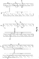
- FIG 1 shows three key stages in the working life of the tubing 1.
- the tubing 1 which comprises the section of tubing 2 with the annular packer 3 mounted on the outer surface, is attached to tubing 6 and delivered down the well bore 5 that has been created in the underground formation 4 using conventional means.
- tubing 1 and 6 are typically connected together above ground and then deployed down the well. However in order to clearly illustrate that tubing 1 and 6 are initially distinct they are initially shown in figure 1 as being separate.
- tubing 1 is attached to the top of the tubing 6 that is already secured in the well 5. It is envisioned that advantageously the tubing 1 of the present invention may be connected to existing production tubing 6 using a collar joint, for example.
- cement 7 can be poured or pumped into the annular space between the formation 4 and the pipework (or, if appropriate, between a well casing/lining and the pipework). Once set the cement 7 will seal the well 5 so that the only access to the oil/gas deposit is via the production tubing 1, 6.
- a heater 8 can be deployed down the well using a wire line 9 or coil tubing, for example, to a target region inside the tubing 1 that is proximate to the eutectic/bismuth based alloy annular packer 3. Once in place the heater 9 can be activated to melt the alloy 3, which causes it to turn into a liquid and flow into the cracks/gaps in the cement plug 7.
- the cement is poured (or pumped) into the annular space after the tubing 1, with its annular packer 3, has been deployed within the well.
- annular packer 3 In arrangements where the diameter of the annular packer 3 is close to the internal diameter of the rock formation 4 (or well casing/lining -not shown) it is considered advantageous to provide the annular packer 3 with conduits to facilitate the passage of cement through and around the annular packer 3 so that it can reach the lower regions of the well 5.
- tubing 1 may also be completely surrounded by and embedded within the cement 7.
- Figures 1a and 1b show such arrangements.
- the tubing shown in Figure 1a has an annular packer 3 of a reduced diameter that does not extend all the way to the outer formation (or casing).
- annular packer 3 of a reduced diameter that does not extend all the way to the outer formation (or casing).
- such embodiment is suitable for sealing micro annuli leaks; such as those formed by constant expansion and contraction of the production tubing (see above).
- the tubing shown in Figure 1b has an annular packer 3 with a diameter that extends to the surrounding formation (or casing). It is envisioned that this embodiment is more suitable for repairing cracks that extend across the entire cement seal.
- Figure 3 shows a first variant of the annular packer 3, which is provided with a plurality of through holes 10.
- the through holes 10 are arranged to permit the passage of wet cement through the main body of the annular packer 3.
- Figure 4 shows a second variant of the annular packer 3, which is provided with a plurality of channels 11 in the outer surface of the annular packer 3. It is envisaged that the provision of conduits is not considered crucial to the operation of the downhole tools.
- FIG. 5 in which is shown a well tool deployment adaptor 12.
- the main components of the adaptor 12 are essentially the same as the tubing shown in Figures 1-4 , in that it comprises a length/section of tubing 13 with a eutectic/bismuth based annular packer 14 mounted on the outside thereof.
- the adaptor 12 further comprises tool engaging means 15 located inside the adaptor.
- the tool engaging means 15 can be of any form provided they are capable of securely engaging/locating a complementary tool within the tubing 13.
- the adaptor 12 is deployed within an existing well tubing structure (e.g. production tubing) and is maintained in place by heating the region of the adaptor proximate to the eutectic/bismuth based alloy and then allowing the alloy cool and fix the adaptor in place within the well by the force of the expanded alloy pressing against the existing well tubing (not shown).
- an existing well tubing structure e.g. production tubing
- the adaptor is provided with a skirt or 'cool area' 18 to slow the flow of the melted alloy 14 so that it is not lost down the well but instead cools in the target region. Further details of suitable skirting can be found in International PCT Application No. WO2011/151271 . It is appreciated that the well fluids will act to quickly cool the heated alloy ensuring that it is not in a flowing state for very long.
- the skirt may further comprise a swellable or intumescent material that is caused to expand when exposed to heat. This further enhances the ability of the skirt to check the flow of the molten alloy so that it can cool in the target region.
- a complementary tool 16 (examples of which include a valve, a flow rate meter or even a temporary, breakable plug) can be delivered down the well using delivery means 17 (e.g. wire line).
- delivery means 17 e.g. wire line
- a heater can be deployed down the well to engage with the tool engaging means 15, heat the alloy and retrieve the adaptor 12.
- Figure 5a shows the adaptor 12 with the tool engagement means hidden to simplify the diagram.
- the tubular body of the adaptor is provided with a weakened point 19. During deployment of the adaptor 12 the weakened point is covered by alloy, this gives additional structural support to the adaptor.
- the weakened point 19 is revealed by the alloy 14. This enables the top portion 12a of the adaptor 12 to be broken off and removed. The removal of the top portion 12a makes any subsequent operations to remove the adaptor 12 easier due to the reduced amount of tubing that needs to be milled out.
- the straddle 171 is configured to be deployable within a well tubing 170 (e.g. a well casing, well lining or other production tubing).
- the straddle 171, which essentially comprises a length of tubing, is provided with two eutectic/bismuth based annular sealing means 172, 173.
- annular sealing means 172, 173 are located at the leading and trailing end regions of the straddle. However it is envisaged that additional annular sealing means may be provided at points along the length of the straddle's outer surface as required (i.e. when the straddle is of an extended length).
- a heater 174 is operated to heat the annular sealing means so that annular seals can be formed between the outer surface of the straddle 171 and the inner surface of the outer tubing 170.
- the embodiment shown uses a heater that has two separate heating modules 175, 176.
- the modules are chemical heat sources.
- the heater and the straddle are preferably deployed down the well as a single unit in which the first heating module 175 is aligned with annular sealing means 172.
- the heater 174 can be detached from the straddle 171 by partially retrieving the heater using the wire line.
- the heater 174 can be delivered using standard delivery means such as a wire line, alternative systems can be used without departing from the present invention.
- the heating module 176 can be activated and the process of forming an annular seal is repeated at the lower end of the straddle to form the annular seal 173a.
- the heater 174 is retrieved from the well using the wire line, for example.
- the straddle shown in figure 6 is provided with two annular sealing means it is envisioned that additional annular sealing means may be provided on the outer surface thereof. It is further envisioned that the heater used to deploy such straddles would advantageous be provided with a corresponding number of heater modules so that the straddle can be fully deployed by the heater in a single visit.
Description
- The present invention relates to downhole well straddle tools suitable for use in a variety of operations within oil and gas wells.
- In order to access oil and gas deposits located in underground formations it is necessary to drill bore holes into these underground formation and deploy production tubing to facilitate the extraction of the oil and gas deposits.
- Additional tubing, in the form of well lining or well casing, may also deployed in locations where the underground formation is unstable and needs to held back to maintain the integrity of the oil/gas well.
- During the formation and completion of an oil/gas well it is crucial to seal the annular space created between the casing and the surrounding formation. Also the annular space between the different sizes casings used as the well is completed. Additionally the annular space between the production tubing and said casing needs to be sealed. Further seals may be required between the underground formation and the additional tubing.
- One of the most common approaches to sealing oil/gas wells is to pump cement into the annular spaces around the casing. The cement hardens to provide a seal which helps ensure that the casing provides the only access to the underground oil and gas deposits. This is crucial for both the efficient operation of the well and controlling any undesirable leakage from the well during or after the well is operated.
- Eventually, once the necessary tubing is secured within an oil or gas well, the operation of a well can commence and extraction can begin. Over the operational lifetime of an oil/gas well situations can arise where it is necessary to deploy downhole tools into the tubing.
- One common task is the carrying out of repairs to the tubing, which due to the downhole environment can develop fractures/leaks over time. Another common task is to isolate (whether temporary or semi-permanent) a region of a well from the rest of the production tubing.
- Various downhole tools are employed in such situations, with some of the most commonly used including bridge plugs, patches, scab and straddles. In order to secure the downhole tool within a well such tools are typically provided with hydraulically actuated means that can be operated to engage with the surface of a surrounding tubing (e.g. a well casing, liner or production tubing).
- A plurality of these engagement means, which are commonly referred to as 'dogs' or 'slips', are normally provided on a downhole tool so that once the tool is in place they can be actuated to lock the tool in position relative to the surrounding tubing.
- Once the required task has been completed by the downhole tool the 'dogs' or 'slips' can be retracted and the tool can be retrieved from the well.
- Although the 'dogs' or 'slips' are suitable to retain the position of a downhole tool within a well they are not capable of providing a gas tight seal with the surrounding tubing. In view of this, on occasions where a gas tight seal is desirable the downhole tool is provided with additional sealing means. This can increase the possibility for a malfunction of the downhole tool.
- Some types of downhole tools, such as expandable patches, are secured in position by expanding the main body of the downhole tool so that it pushes against the inner surface of the outer tubing.
-
US 2,942,668 relates to a well plugging and/or testing tool that employs meltable materials that expand on melting to form annular seals with a borehole.WO 02/099247 US 2780294 A relates to a packer assembly formed from multiple component pack.WO 03/083255 A1 - The present invention seeks to utilise alternative means for securely positioning downhole tools within oil or gas wells that provide a viable alternative to the systems (such as hydraulically actuated means; e.g. 'dogs', 'slips') commonly used in existing downhole tools.
- To this end the present invention employs the use of eutectic/bismuth based alloy annular packers described hereinafter as an alternative means for temporarily or permanently securing a downhole tool within an oil or gas well.
- The annular packers described throughout essentially consist of a reservoir of eutectic/bismuth based alloy that is mounted on the outer surface of a section of tubing. The alloy can be melted to form a seal between the outer surface of the tubing and the inner surface of surrounding tubing.
- It is appreciated that the seal formed can be used to not only provide a gas tight seal but also secure the inner tubing in position within the outer tubing. In view of this and to avoid any confusion the annular packers that are used in the downhole tools of the present invention can also be referred to as annular seals or annular sealing means. The terms 'annular packer', 'annular sealing means' and 'annular seal' are therefore considered to be interchangeable when used in connection the downhole tools of the present invention.
- The general concept of the annular packers, which are described herein for information purposes only, are the subject a separate patent application.
- The present invention provides a downhole straddle tool in accordance with
claim 1 and a downhole straddle tool deployment assembly in accordance withclaim 4. - In order to aid the description of the downhole straddle tool of the present invention a gas or oil well tubing having an annular packer mounted thereon, wherein the annular packer is formed from a eutectic or other bismuth based alloy, is described.
- Preferably, the annular packer may comprise multiple component parts which are combinable to form the complete annulus when mounted on the tubing. In this way the production step of mounting the annular packer on the tubing is made quicker and easier.
- Further preferably the multiple component parts may consist of two or more ring segments which can be connected together to form a complete annular packer that encircles the tubing.
- The provision of at least one annular sealing means on the outer surface of the tubing enables the formation of an annular seal between the outer surface of the tool and the inner surface of a surrounding well tubing/casing. It is appreciated that the ability to set and unset the annular seal with a heater deployed within the well facilitates the easy deployment and removal of these downhole tools, which are normally, although not always, only required for a limited period of time.
- In order to enable the downhole tool to be delivered down the well the tool is preferably provided with attachment means for connecting the tool to a delivery tool, for example by way of a wire line or a setting tool. Further preferably the attachment means comprise shear pins so that the wire line can be retrieved from the well once the downhole tool has been secured in position by the annular sealing means.
- Preferably the tubing may also have a weak point just above the 'slump' line of the set alloy. In this way the tool length can be reduced after setting, which reduces the operational costs if the tool needs to be removed in future, e.g. by milling.
- Preferably the tubing is formed from two sections that are held together, at least in part, by a eutectic/bismuth based alloy. Further preferably the attachment means for connecting the downhole tool to the delivery tool (e.g. via a wire line) can be located on the section of the tubing that is released/revealed when the alloy sags.
- In this way a section of the tubing can be retrieved from the well. This is considered particularly advantageous because it reduces the amount of material that needs to be removed from the well in the event that milling or drilling is used.
- Further preferably the section of the tubing that remains in the well may be formed from a softer material (e.g. aluminium) than the section with the delivery tool attachment means. In this way any subsequent milling/drilling out of the downhole tool is made easier/quicker.
- Preferably the section of the tubing that remains in the well may have walls that are thinner that at least a portion of the section with the delivery tool attachment means. Once again this will facilitate easier milling/drilling out of the downhole tool.
- It is appreciated that varying the length of the tubing can provide a variety of downhole tools that range from patches, which have a shorter length of tubing, to the straddle tools of the present invention, which have a considerably longer length of tubing, and scabs, which can be have length of tubing that is somewhere in between..
- 2. Although, not covered by the claims, it is appreciated that the size, number and positioning of the eutectic/bismuth based alloy annular sealing means provided on the outer surface of the tubing will vary from tool to tool. For example it is considered appropriate that the size (and possibly the number) of the annular sealing means used on a straddle would be greater than required for a patch due to the much greater weight load being carried by the annular seals formed between the outer well tubing and the downhole tool.
- The present invention also provides a method of manufacturing the downhole straddle tool of the present invention in accordance with
claim 7. - Specifically the present invention provides a method of manufacturing a downhole straddle tool for use in oil and gas wells, said method comprising: providing a length of tubing; mounting two eutectic/bismuth based alloy annular sealing means to an outer surface of the tubing.
- Preferably the annular sealing means is provided in the form of multiple component parts and the step of mounting the annular sealing means to the tubing involves securing the component parts together around the circumference of the tubing to complete the annulus. This approach is considered most appropriate for producing the variants of the tubing according to the present invention that has the annular sealing means mounted on the outer surface thereof.
- A chemical heater, is deployed down the well to apply heat to the eutectic/bismuth based annular sealing means and cause it to melt. Alternatively the tubing may further comprise heating means that can be activated remotely to melt the alloy. In such an arrangement the heating means are preferably in the form of a chemical heat source.
- The present invention will now be described with reference to the drawings, wherein:
-
Figure 1 is a diagrammatic representation of the key stages of the deployment and operation of the oil/gas well tubing of an tubing with an annular packer that is provided for information purposes only; -
Figure 1a is a diagrammatic representation of an alternative deployment of the tubing with an annular packer that is provided for information purposes only; -
Figure 1b is a diagrammatic representation of a second alternative deployment of the tubing with an annular packer that is provided for information purposes only; -
Figure 2 shows a perspective view of an annular packer being used as a annular sealing means mounted on the outer surface of tubing which can form the basis for a downhole straddle tool in accordance with the present invention; -
Figure 3 shows an end view of one variant of the annular sealing means shown inFigure 2 that is not considered to form part of the present invention; -
Figure 4 shows an end view of a second variant of the annular sealing means shown inFigure 2 that is not considered to form part of the present invention; -
Figure 5 shows a diagrammatic cross-sectional representation of a well tool deployment adaptor that is not considered to form part of the present invention; -
Figure 5a shows a diagrammatic representation of the key stages of the deployment and operation of downhole tool that is not considered to form part of the present invention; -
Figure 6 shows a diagrammatic cross-sectional representation of the key stages of the deployment of a straddle downhole tool according to the present invention. - The various downhole tools will now be described with reference to the Figures, which provide a collection of diagrammatic representations of downhole tools. An embodiment of the straddle tool of the present invention is shown in
Figure 6 , the other figures are provided for information purposes only. - One of the central features of tools shown in the figures is formation of prefabricated oil/gas tubing with a eutectic/bismuth based alloy annular packer mounted to the said tubing. Although the term annular packer is used it is appreciated that the terms annular sealing means, annular seal and thermally deformable annulus packer may also employed depending on the context of the tool being described. The terms can therefore be used interchangeably.
- The term prefabricated is intended to cover situations where the annular packer/annular sealing means is mounted on the tubing either in a factory or on site, but always before the tubing is deployed down a well bore. This is clearly distinct from existing uses of alloy as a sealant, wherein the alloy is deployed separately from the tubing at a later stage - which is usually after completion of the well.
- It will be appreciated that, unless otherwise specified, the materials used to manufacture the components of the various apparatus described hereinafter will be of a conventional nature in the field of oil/gas well production.
- The downhole straddle tool of the present invention utilises alloy annular packers or annular sealing means rather than more traditional mechanical means (e.g. 'dogs' or 'slips') to retain the tools in position within a well. In order to better understand the annular packers upon which the annular sealing means present invention is based such will now be described with reference to
figures 1-4 . -
Figure 2 shows an oil/gas well tubing 1 suitable for use with the downhole straddle tool of the present invention in the form of a length/section ofpipe 2 with a eutectic/bismuth based alloyannular packer 3 mounted on the outside thereof. - Although not shown in the Figures it is envisioned that the externally mounted annular packer might preferably be formed from multiple component parts that combine to surround the length of
production pipe 2 so that the process of mounting (and possibly remounting) the annular packer is made easier. - As will be appreciated from
Figure 1 the diameter of theannular packer 3 is sufficient to provide a close fit with the outer wall of the well 5, which may be provided by arock formation 4 or as appropriate a well casing or lining. - In order to explain the use of the
tubing 1 reference is made toFigure 1 , which shows three key stages in the working life of thetubing 1. In the first stage thetubing 1, which comprises the section oftubing 2 with theannular packer 3 mounted on the outer surface, is attached to tubing 6 and delivered down the well bore 5 that has been created in theunderground formation 4 using conventional means. - It is appreciated that
tubing 1 and 6 are typically connected together above ground and then deployed down the well. However in order to clearly illustrate thattubing 1 and 6 are initially distinct they are initially shown infigure 1 as being separate. - In the reference Figures the
tubing 1 is attached to the top of the tubing 6 that is already secured in the well 5. It is envisioned that advantageously thetubing 1 of the present invention may be connected to existing production tubing 6 using a collar joint, for example. - Once the production pipework, which comprises
tubing 1 and 6, has been deployed within the well 5cement 7 can be poured or pumped into the annular space between theformation 4 and the pipework (or, if appropriate, between a well casing/lining and the pipework). Once set thecement 7 will seal the well 5 so that the only access to the oil/gas deposit is via theproduction tubing 1, 6. - In the event that a crack or gap develops in the cement seal and forms a leak a
heater 8 can be deployed down the well using awire line 9 or coil tubing, for example, to a target region inside thetubing 1 that is proximate to the eutectic/bismuth based alloyannular packer 3. Once in place theheater 9 can be activated to melt thealloy 3, which causes it to turn into a liquid and flow into the cracks/gaps in thecement plug 7. - When the
alloy 3 of the annular packer cools it expands and plugs the cracks/gaps and reseals thecement plug 7 and stops the leak. - It is appreciated that various annular spaces are created during the formation of a well and it is envisioned that the present invention can therefore be usefully employed in variety of different arrangements without departing from the scope of the present invention.
- In the referenced Figures the cement is poured (or pumped) into the annular space after the
tubing 1, with itsannular packer 3, has been deployed within the well. - In arrangements where the diameter of the
annular packer 3 is close to the internal diameter of the rock formation 4 (or well casing/lining -not shown) it is considered advantageous to provide theannular packer 3 with conduits to facilitate the passage of cement through and around theannular packer 3 so that it can reach the lower regions of the well 5. - It is envisioned that rather than being deployed above the level of the cement the
tubing 1 may also be completely surrounded by and embedded within thecement 7.Figures 1a and 1b show such arrangements. - The tubing shown in
Figure 1a has anannular packer 3 of a reduced diameter that does not extend all the way to the outer formation (or casing). In is envisioned that such embodiment is suitable for sealing micro annuli leaks; such as those formed by constant expansion and contraction of the production tubing (see above). - The tubing shown in
Figure 1b has anannular packer 3 with a diameter that extends to the surrounding formation (or casing). It is envisioned that this embodiment is more suitable for repairing cracks that extend across the entire cement seal. -
Figure 3 shows a first variant of theannular packer 3, which is provided with a plurality of throughholes 10. The through holes 10 are arranged to permit the passage of wet cement through the main body of theannular packer 3. -
Figure 4 shows a second variant of theannular packer 3, which is provided with a plurality of channels 11 in the outer surface of theannular packer 3. It is envisaged that the provision of conduits is not considered crucial to the operation of the downhole tools. - Turning now to
Figure 5 , in which is shown a welltool deployment adaptor 12. It will be appreciated that the main components of theadaptor 12 are essentially the same as the tubing shown inFigures 1-4 , in that it comprises a length/section oftubing 13 with a eutectic/bismuth basedannular packer 14 mounted on the outside thereof. - However the
adaptor 12 further comprises tool engaging means 15 located inside the adaptor. The tool engaging means 15 can be of any form provided they are capable of securely engaging/locating a complementary tool within thetubing 13. - In use the
adaptor 12 is deployed within an existing well tubing structure (e.g. production tubing) and is maintained in place by heating the region of the adaptor proximate to the eutectic/bismuth based alloy and then allowing the alloy cool and fix the adaptor in place within the well by the force of the expanded alloy pressing against the existing well tubing (not shown). - The adaptor is provided with a skirt or 'cool area' 18 to slow the flow of the melted
alloy 14 so that it is not lost down the well but instead cools in the target region. Further details of suitable skirting can be found in InternationalPCT Application No. WO2011/151271 . It is appreciated that the well fluids will act to quickly cool the heated alloy ensuring that it is not in a flowing state for very long. - Although not shown, it is envisaged that the skirt may further comprise a swellable or intumescent material that is caused to expand when exposed to heat. This further enhances the ability of the skirt to check the flow of the molten alloy so that it can cool in the target region.
- Once the adaptor is secured in place within the well a complementary tool 16 (examples of which include a valve, a flow rate meter or even a temporary, breakable plug) can be delivered down the well using delivery means 17 (e.g. wire line).
- When the time comes to remove the
adaptor 12 a heater can be deployed down the well to engage with thetool engaging means 15, heat the alloy and retrieve theadaptor 12. -
Figure 5a shows theadaptor 12 with the tool engagement means hidden to simplify the diagram. The tubular body of the adaptor is provided with a weakenedpoint 19. During deployment of theadaptor 12 the weakened point is covered by alloy, this gives additional structural support to the adaptor. - Once in situ, and the alloy has been melted to secure the adaptor in place, the weakened
point 19 is revealed by thealloy 14. This enables thetop portion 12a of theadaptor 12 to be broken off and removed. The removal of thetop portion 12a makes any subsequent operations to remove theadaptor 12 easier due to the reduced amount of tubing that needs to be milled out. - An embodiment of the downhole straddle tool of the present invention in the form of a
straddle 171 will now be described with reference tofigure 6 , which show the key stages of a straddle deployment operation. - The
straddle 171 is configured to be deployable within a well tubing 170 (e.g. a well casing, well lining or other production tubing). Thestraddle 171, which essentially comprises a length of tubing, is provided with two eutectic/bismuth based annular sealing means 172, 173. - The annular sealing means 172, 173 are located at the leading and trailing end regions of the straddle. However it is envisaged that additional annular sealing means may be provided at points along the length of the straddle's outer surface as required (i.e. when the straddle is of an extended length).
- Once the straddle reaches the target region within the well a
heater 174 is operated to heat the annular sealing means so that annular seals can be formed between the outer surface of thestraddle 171 and the inner surface of theouter tubing 170. - In
figure 6 the embodiment shown uses a heater that has twoseparate heating modules - Once the
first heating module 175 is aligned with the annular sealing means 172 located at the trailing end of thestraddle 171 the heat is activated and the alloy of the annular sealing means 172 is melted and allowed to sag. As the alloy sags and cools an annular seal is formed between thestraddle 171 and theouter tubing 170. Although not shown in figures it is envisioned that the heater and the straddle are preferably deployed down the well as a single unit in which thefirst heating module 175 is aligned with annular sealing means 172. - Once the
first heating module 175 has finished and the upperannular seal 172a has been formed, and the straddle is secured in position in the well, theheater 174 can be detached from thestraddle 171 by partially retrieving the heater using the wire line. - Once the heater has been released from the straddle it can be deployed further down the well via the internal cavity of the
straddle 171. As will be appreciated although theheater 174 can be delivered using standard delivery means such as a wire line, alternative systems can be used without departing from the present invention. - Once the
second heating module 176 is aligned with lower annular sealing means 173 the heating module can be activated and the process of forming an annular seal is repeated at the lower end of the straddle to form theannular seal 173a. - Once the second
annular seal 173a has been set theheater 174 is retrieved from the well using the wire line, for example. - Although the straddle shown in
figure 6 is provided with two annular sealing means it is envisioned that additional annular sealing means may be provided on the outer surface thereof. It is further envisioned that the heater used to deploy such straddles would advantageous be provided with a corresponding number of heater modules so that the straddle can be fully deployed by the heater in a single visit.
Claims (8)
- A downhole straddle tool (171) for deployment within a gas or oil well tubing, said straddle tool (171) comprising a length of tubing having a first annular sealing means (173) mounted on the outer surface of the tubing at a leading end thereof and a second annular sealing means (172) mounted on the outer surface of the tubing at a trailing end thereof; and
wherein the first and second annular sealing means are formed from a eutectic/bismuth based alloy that expands as it cools from a molten liquid state to a solid state, such that, in use, the alloy of each annular sealing means is melted to form a seal between the outer surface of the tubing and an inner surface of a surrounding gas or oil well tubing. - The downhole straddle tool (171) of claim 1, wherein one or more additional annular sealing means are provided at points along the length of the tubing.
- The downhole straddle tool of any of the preceding claims, wherein each of said annular sealing means comprise multiple component parts which combine to form the complete annulus when mounted on the tubing.
- A downhole straddle tool deployment assembly, said assembly comprising:a downhole straddle tool according to any of claims 1 to 3;a heater (174) having at least two separate heating modules (175, 176), said heating modules being located at the leading end and the trailing end of the heater respectively; andwherein the heater (174) is detachably mounted to the downhole straddle tool such that the heating module (175) located at the leading end of the heater is aligned with the second annular sealing means (172).
- The deployment assembly of claim 4, wherein said heating modules (175, 176) are chemical heat sources.
- A downhole chemical heater (174) for use in the deployment of the downhole straddle tool (171) of any of claims 1 to 3, wherein said heater comprises a first chemical heating module (175) at a leading end of the heater and a second chemical heating module (176) at a trailing end of the heater.
- A method of manufacturing a downhole straddle tool (171) according to any one of claims 1 to 3, said method comprising:providing a length of tubing;mounting a first eutectic/bismuth based annular sealing means (173) on the outer surface of the tubing at a leading end thereof; andmounting a second eutectic/bismuth based annular sealing means (172) on the outer surface of the tubing at a trailing end thereof.
- The method of manufacturing a downhole straddle tool of claim 7, wherein each annular sealing means is provided in the form of multiple component parts and the steps of mounting the annular sealing means to the tubing involve securing the component parts together around the circumference of the tubing to complete the annulus.
Applications Claiming Priority (4)
| Application Number | Priority Date | Filing Date | Title |
|---|---|---|---|
| GBGB1414565.0A GB201414565D0 (en) | 2014-08-15 | 2014-08-15 | Methods and apparatus for use in oil and gas well completion |
| GB1505750.8A GB2529275B (en) | 2014-08-15 | 2015-04-02 | Methods and apparatus for use in oil and gas well completion |
| EP15753149.2A EP3180492B1 (en) | 2014-08-15 | 2015-08-14 | Downhole well tools and methods of using such |
| PCT/GB2015/052348 WO2016024123A1 (en) | 2014-08-15 | 2015-08-14 | Downhole well tools and methods of using such |
Related Parent Applications (1)
| Application Number | Title | Priority Date | Filing Date |
|---|---|---|---|
| EP15753149.2A Division EP3180492B1 (en) | 2014-08-15 | 2015-08-14 | Downhole well tools and methods of using such |
Publications (2)
| Publication Number | Publication Date |
|---|---|
| EP3578749A1 EP3578749A1 (en) | 2019-12-11 |
| EP3578749B1 true EP3578749B1 (en) | 2022-05-25 |
Family
ID=51662526
Family Applications (5)
| Application Number | Title | Priority Date | Filing Date |
|---|---|---|---|
| EP15753149.2A Active EP3180492B1 (en) | 2014-08-15 | 2015-08-14 | Downhole well tools and methods of using such |
| EP15753981.8A Active EP3126617B1 (en) | 2014-08-15 | 2015-08-14 | A downhole fishing tool |
| EP19172004.4A Active EP3578749B1 (en) | 2014-08-15 | 2015-08-14 | Downhole straddle tools |
| EP22198301.8A Pending EP4130425A1 (en) | 2014-08-15 | 2015-08-14 | Methods and apparatus for use in oil and gas well completion |
| EP15753148.4A Active EP3180491B1 (en) | 2014-08-15 | 2015-08-14 | Methods and apparatus for use in oil and gas well completion |
Family Applications Before (2)
| Application Number | Title | Priority Date | Filing Date |
|---|---|---|---|
| EP15753149.2A Active EP3180492B1 (en) | 2014-08-15 | 2015-08-14 | Downhole well tools and methods of using such |
| EP15753981.8A Active EP3126617B1 (en) | 2014-08-15 | 2015-08-14 | A downhole fishing tool |
Family Applications After (2)
| Application Number | Title | Priority Date | Filing Date |
|---|---|---|---|
| EP22198301.8A Pending EP4130425A1 (en) | 2014-08-15 | 2015-08-14 | Methods and apparatus for use in oil and gas well completion |
| EP15753148.4A Active EP3180491B1 (en) | 2014-08-15 | 2015-08-14 | Methods and apparatus for use in oil and gas well completion |
Country Status (8)
| Country | Link |
|---|---|
| US (7) | US10309187B2 (en) |
| EP (5) | EP3180492B1 (en) |
| CA (3) | CA2987496C (en) |
| DK (4) | DK3180491T3 (en) |
| GB (2) | GB201414565D0 (en) |
| NO (1) | NO3126617T3 (en) |
| SA (2) | SA517380902B1 (en) |
| WO (3) | WO2016024123A1 (en) |
Families Citing this family (22)
| Publication number | Priority date | Publication date | Assignee | Title |
|---|---|---|---|---|
| GB2480869B (en) | 2010-06-04 | 2017-01-11 | Bisn Tec Ltd | Method and apparatus for use in well abandonment |
| GB201223055D0 (en) | 2012-12-20 | 2013-02-06 | Carragher Paul | Method and apparatus for use in well abandonment |
| GB201406071D0 (en) | 2014-04-04 | 2014-05-21 | Bisn Tec Ltd | Well Casing / Tubing Disposal |
| GB201414565D0 (en) | 2014-08-15 | 2014-10-01 | Bisn Oil Tools Ltd | Methods and apparatus for use in oil and gas well completion |
| WO2018033760A1 (en) * | 2016-08-19 | 2018-02-22 | Bisn Tec Ltd | Downhole operations relating to open hole gravel packs and tools for use therein |
| GB2551693B (en) | 2016-05-24 | 2021-09-15 | Bisn Tec Ltd | Down-hole chemical heater and methods of operating such |
| GB2562208B (en) * | 2017-04-04 | 2021-04-07 | Bisn Tec Ltd | Improvements relating to thermally deformable annular packers |
| CA3062623A1 (en) * | 2017-05-01 | 2018-11-08 | Conocophillips Company | Metal seal for liner drilling |
| CA3100822A1 (en) * | 2017-05-24 | 2018-11-29 | Bisn Tec Ltd | A downhole tool deployment assembly with improved heater removability and methods of employing such |
| WO2019006141A1 (en) * | 2017-06-29 | 2019-01-03 | Conocophillips Company | Methods, systems, and devices for sealing stage tool leaks |
| GB2568519B (en) | 2017-11-17 | 2022-09-28 | Bisn Tec Ltd | An expandable eutectic alloy based downhole tool and methods of deploying such |
| US10844699B2 (en) * | 2018-05-29 | 2020-11-24 | Saudi Arabian Oil Company | By-pass system and method for inverted ESP completion |
| US11846418B2 (en) * | 2018-12-28 | 2023-12-19 | Robertson Intellectual Properties, LLC | Protective material for fuel system |
| GB2583372B (en) * | 2019-04-26 | 2022-03-02 | Isol8 Holdings Ltd | Downhole sealing methods and apparatus |
| US10975658B2 (en) | 2019-05-17 | 2021-04-13 | Baker Hughes Oilfield Operations Llc | Wellbore isolation barrier including negative thermal expansion material |
| NO20210121A1 (en) * | 2020-02-10 | 2021-08-11 | Wellbore Integrity Solutions Llc | Patch for joining downhole ends of pipes |
| WO2021260442A1 (en) | 2020-06-22 | 2021-12-30 | Bisn Tec Ltd. | Plug with composite ends and method of forming and using |
| US11448034B2 (en) | 2020-07-13 | 2022-09-20 | Saudi Arabian Oil Company | Removable plugging method and apparatus |
| CA3189554A1 (en) * | 2020-07-15 | 2022-01-20 | Conocophillips Company | Well collapse reconnect system |
| GB202111796D0 (en) | 2021-08-17 | 2021-09-29 | Bisn Tec Ltd | A downhole external catch tool and methods of using such |
| GB2612622A (en) | 2021-11-05 | 2023-05-10 | Bisn Tec Ltd | A chemical reaction heat source composition for use in downhole operations and associated apparatus and methods |
| WO2023214175A1 (en) | 2022-05-04 | 2023-11-09 | Bisn Tec Ltd | Methods to remove alloy plugs and annular seals and associated apparatus |
Family Cites Families (81)
| Publication number | Priority date | Publication date | Assignee | Title |
|---|---|---|---|---|
| US1534229A (en) | 1924-07-12 | 1925-04-21 | Gerald R Livergood | Fishing tool |
| US2076308A (en) | 1936-02-15 | 1937-04-06 | Technicraft Engineering Corp | Well heating device and method |
| US2686689A (en) * | 1950-04-29 | 1954-08-17 | Pyke Herbert Douglas | Method and apparatus for retrieving junk from well bores |
| US2789004A (en) | 1954-03-17 | 1957-04-16 | Henry C Foster | Metal fishing tool |
| US2780294A (en) * | 1955-05-02 | 1957-02-05 | John Stahl | Packer assembly |
| US2822876A (en) | 1955-10-26 | 1958-02-11 | M & M Mfg Company Inc | Deep well bridge |
| US2942668A (en) * | 1957-11-19 | 1960-06-28 | Union Oil Co | Well plugging, packing, and/or testing tool |
| US3119451A (en) | 1961-01-09 | 1964-01-28 | John A Hall | Cement basket |
| US3170516A (en) | 1962-06-25 | 1965-02-23 | Jersey Prod Res Co | Method of plugging a well bore with a thermosetting resin |
| US3208530A (en) | 1964-09-14 | 1965-09-28 | Exxon Production Research Co | Apparatus for setting bridge plugs |
| US3871315A (en) | 1973-06-20 | 1975-03-18 | Leonard Morgansen Andersen | Device for salvaging metal objects and salvaging method |
| US4134452A (en) | 1977-09-14 | 1979-01-16 | Gulf Research & Development Company | Well testing tool |
| DE2809181B2 (en) | 1978-03-03 | 1980-07-24 | Guenter 4520 Melle Kreft | Safety centering basket |
| US4270761A (en) * | 1979-12-03 | 1981-06-02 | Seals Eastern Inc. | Seal for geothermal wells and the like |
| GB2164886A (en) | 1981-02-23 | 1986-04-03 | Hot Hed Inc | Welding preheating insert for heavy wall pipe |
| US4423783A (en) | 1982-04-23 | 1984-01-03 | Texaco Inc. | Method for plugging a well and bridge plug |
| US4488747A (en) * | 1982-08-12 | 1984-12-18 | George Austin | Method and fishing tool apparatus for recovering objects from wells |
| US4487747A (en) * | 1983-05-05 | 1984-12-11 | Laporte Industries Limited | Production of metal chlorides |
| US4523640A (en) | 1984-01-23 | 1985-06-18 | Dresser Industries, Inc. | Arm release system for well logging apparatus |
| US4696343A (en) | 1986-05-23 | 1987-09-29 | S.I.E., Inc. | Wireline dump bailer |
| US5052489A (en) | 1990-06-15 | 1991-10-01 | Carisella James V | Apparatus for selectively actuating well tools |
| US5564861A (en) | 1995-06-06 | 1996-10-15 | Khudenko; Boris M. | Thermal method of in-situ soil treatment |
| US5833001A (en) | 1996-12-13 | 1998-11-10 | Schlumberger Technology Corporation | Sealing well casings |
| US6474414B1 (en) | 2000-03-09 | 2002-11-05 | Texaco, Inc. | Plug for tubulars |
| US6664522B2 (en) | 2000-03-30 | 2003-12-16 | Homer L. Spencer | Method and apparatus for sealing multiple casings for oil and gas wells |
| US6828531B2 (en) | 2000-03-30 | 2004-12-07 | Homer L. Spencer | Oil and gas well alloy squeezing method and apparatus |
| US6454001B1 (en) | 2000-05-12 | 2002-09-24 | Halliburton Energy Services, Inc. | Method and apparatus for plugging wells |
| US7455104B2 (en) * | 2000-06-01 | 2008-11-25 | Schlumberger Technology Corporation | Expandable elements |
| GB0023543D0 (en) | 2000-09-26 | 2000-11-08 | Rawwater Engineering Company L | Sealing method and apparatus |
| NO335594B1 (en) | 2001-01-16 | 2015-01-12 | Halliburton Energy Serv Inc | Expandable devices and methods thereof |
| GB0108384D0 (en) | 2001-04-04 | 2001-05-23 | Weatherford Lamb | Bore-lining tubing |
| MY130896A (en) * | 2001-06-05 | 2007-07-31 | Shell Int Research | In-situ casting of well equipment |
| GB0207371D0 (en) * | 2002-03-28 | 2002-05-08 | Rawwater Engineering Company L | Sealing method and apparatus |
| US6766858B2 (en) * | 2002-12-04 | 2004-07-27 | Halliburton Energy Services, Inc. | Method for managing the production of a well |
| US7048048B2 (en) | 2003-06-26 | 2006-05-23 | Halliburton Energy Services, Inc. | Expandable sand control screen and method for use of same |
| GB2442636B (en) * | 2004-01-12 | 2008-10-08 | Shell Oil Co | Expandable connection |
| US7055595B2 (en) * | 2004-04-02 | 2006-06-06 | Baker Hughes Incorporated | Electrical submersible pump actuated packer |
| US7290609B2 (en) | 2004-08-20 | 2007-11-06 | Cinaruco International S.A. Calle Aguilino De La Guardia | Subterranean well secondary plugging tool for repair of a first plug |
| US20060144591A1 (en) | 2004-12-30 | 2006-07-06 | Chevron U.S.A. Inc. | Method and apparatus for repair of wells utilizing meltable repair materials and exothermic reactants as heating agents |
| US7934552B2 (en) | 2005-09-08 | 2011-05-03 | Thomas La Rovere | Method and apparatus for well casing repair and plugging utilizing molten metal |
| US8151895B1 (en) * | 2006-02-17 | 2012-04-10 | Baker Hughes Incorporated | Eutectic salt inflated wellbore tubular patch |
| CA2579116C (en) * | 2006-02-17 | 2011-09-20 | Innicor Subsurface Technologies Inc. | Eutectic material-based seal element for packers |
| US20080047708A1 (en) | 2006-06-24 | 2008-02-28 | Spencer Homer L | Method and apparatus for plugging perforations |
| EP1933004A1 (en) | 2006-12-12 | 2008-06-18 | Shell Internationale Researchmaatschappij B.V. | Method of controlling hardening of a compound in a wellbore |
| US8327926B2 (en) | 2008-03-26 | 2012-12-11 | Robertson Intellectual Properties, LLC | Method for removing a consumable downhole tool |
| US20100006289A1 (en) | 2008-05-13 | 2010-01-14 | Spencer Homer L | Method and apparatus for sealing abandoned oil and gas wells |
| US7841417B2 (en) | 2008-11-24 | 2010-11-30 | Halliburton Energy Services, Inc. | Use of swellable material in an annular seal element to prevent leakage in a subterranean well |
| US20100263876A1 (en) | 2009-04-21 | 2010-10-21 | Frazier W Lynn | Combination down hole tool |
| EP2243920A1 (en) * | 2009-04-22 | 2010-10-27 | Tenaris Connections Aktiengesellschaft | Threaded joint for tubes, pipes and the like |
| US20110155377A1 (en) * | 2009-06-29 | 2011-06-30 | Laun Lyle E | Joint or coupling device incorporating a mechanically-induced weak point and method of use |
| US20110036570A1 (en) * | 2009-08-14 | 2011-02-17 | La Rovere Thomas A | Method and apparatus for well casing shoe seal |
| US8297368B2 (en) * | 2009-10-28 | 2012-10-30 | Chevron U.S.A. Inc. | Systems and methods for initiating annular obstruction in a subsurface well |
| US8191644B2 (en) * | 2009-12-07 | 2012-06-05 | Schlumberger Technology Corporation | Temperature-activated swellable wellbore completion device and method |
| US8196515B2 (en) | 2009-12-09 | 2012-06-12 | Robertson Intellectual Properties, LLC | Non-explosive power source for actuating a subsurface tool |
| CA2688704C (en) | 2009-12-15 | 2016-04-26 | Rawwater Engineering Company Limited | Sealing method and apparatus |
| US8685187B2 (en) | 2009-12-23 | 2014-04-01 | Schlumberger Technology Corporation | Perforating devices utilizing thermite charges in well perforation and downhole fracing |
| US8839871B2 (en) | 2010-01-15 | 2014-09-23 | Halliburton Energy Services, Inc. | Well tools operable via thermal expansion resulting from reactive materials |
| EP2362062A1 (en) | 2010-02-22 | 2011-08-31 | Welltec A/S | An annular barrier |
| EP2575753A1 (en) | 2010-05-31 | 2013-04-10 | Unilever NV | Skin treatment composition |
| GB2480869B (en) | 2010-06-04 | 2017-01-11 | Bisn Tec Ltd | Method and apparatus for use in well abandonment |
| GB2485811B (en) * | 2010-11-25 | 2017-09-20 | M-I Drilling Fluids U K Ltd | Downhole tool and method |
| CA2819371C (en) * | 2010-12-17 | 2016-11-29 | Exxonmobil Upstream Research Company | Wellbore apparatus and methods for multi-zone well completion, production and injection |
| EP2773841B1 (en) | 2011-11-04 | 2016-11-02 | Halliburton Energy Services, Inc. | Methods of severing an object from the outside using heat evolved from an exothermic reaction |
| US9534701B2 (en) | 2012-02-01 | 2017-01-03 | Halliburton Energy Services, Inc. | Opening or closing a fluid flow path using a material that expands or contracts via a change in temperature |
| CA2871741C (en) * | 2012-06-04 | 2018-02-13 | Exxonmobil Upstream Research Company | Wellbore assembly for injecting a fluid into a subsurface formation, and method of injecting fluids into a subsurface formation |
| NO337410B1 (en) * | 2012-07-23 | 2016-04-11 | Plugtech As | Plug for temporary installation in a well |
| GB201223055D0 (en) | 2012-12-20 | 2013-02-06 | Carragher Paul | Method and apparatus for use in well abandonment |
| US9790755B2 (en) | 2013-04-24 | 2017-10-17 | Halliburton Energy Services, Inc. | Positive displacement dump bailer and method of operation |
| WO2014187795A1 (en) * | 2013-05-22 | 2014-11-27 | Fmc Kongsberg Subsea As | Seal element |
| US9447655B2 (en) * | 2013-10-15 | 2016-09-20 | Baker Hughes Incorporated | Methods for hanging liner from casing and articles derived therefrom |
| US20150211327A1 (en) | 2014-01-30 | 2015-07-30 | Olympic Research, Inc. | Well sealing via thermite reactions |
| US9228412B2 (en) | 2014-01-30 | 2016-01-05 | Olympic Research, Inc. | Well sealing via thermite reactions |
| US20150211328A1 (en) | 2014-01-30 | 2015-07-30 | Olympic Research, Inc. | Well sealing via thermite reactions |
| GB201406071D0 (en) | 2014-04-04 | 2014-05-21 | Bisn Tec Ltd | Well Casing / Tubing Disposal |
| GB201414565D0 (en) | 2014-08-15 | 2014-10-01 | Bisn Oil Tools Ltd | Methods and apparatus for use in oil and gas well completion |
| US10072477B2 (en) | 2014-12-02 | 2018-09-11 | Schlumberger Technology Corporation | Methods of deployment for eutectic isolation tools to ensure wellbore plugs |
| US20170251231A1 (en) | 2015-01-05 | 2017-08-31 | Gitcirrus, Llc | System and Method for Media Synchronization and Collaboration |
| US10352109B2 (en) * | 2015-05-20 | 2019-07-16 | Schlumberger Technology Corporation | System and methodology for coupling tubing |
| GB2551693B (en) | 2016-05-24 | 2021-09-15 | Bisn Tec Ltd | Down-hole chemical heater and methods of operating such |
| GB2562208B (en) | 2017-04-04 | 2021-04-07 | Bisn Tec Ltd | Improvements relating to thermally deformable annular packers |
| CA3062623A1 (en) * | 2017-05-01 | 2018-11-08 | Conocophillips Company | Metal seal for liner drilling |
-
2014
- 2014-08-15 GB GBGB1414565.0A patent/GB201414565D0/en not_active Ceased
-
2015
- 2015-04-02 GB GB1505750.8A patent/GB2529275B/en active Active
- 2015-08-14 DK DK15753148.4T patent/DK3180491T3/en active
- 2015-08-14 EP EP15753149.2A patent/EP3180492B1/en active Active
- 2015-08-14 DK DK15753981.8T patent/DK3126617T3/en active
- 2015-08-14 US US15/309,789 patent/US10309187B2/en active Active
- 2015-08-14 WO PCT/GB2015/052348 patent/WO2016024123A1/en active Application Filing
- 2015-08-14 CA CA2987496A patent/CA2987496C/en active Active
- 2015-08-14 WO PCT/GB2015/052346 patent/WO2016024121A1/en active Application Filing
- 2015-08-14 CA CA2987546A patent/CA2987546C/en active Active
- 2015-08-14 EP EP15753981.8A patent/EP3126617B1/en active Active
- 2015-08-14 WO PCT/GB2015/052347 patent/WO2016024122A2/en active Application Filing
- 2015-08-14 NO NO15753981A patent/NO3126617T3/no unknown
- 2015-08-14 DK DK19172004.4T patent/DK3578749T3/en active
- 2015-08-14 EP EP19172004.4A patent/EP3578749B1/en active Active
- 2015-08-14 EP EP22198301.8A patent/EP4130425A1/en active Pending
- 2015-08-14 US US15/502,960 patent/US10961806B2/en active Active
- 2015-08-14 US US15/502,966 patent/US10370931B2/en active Active
- 2015-08-14 CA CA2987506A patent/CA2987506C/en active Active
- 2015-08-14 DK DK15753149.2T patent/DK3180492T3/en active
- 2015-08-14 EP EP15753148.4A patent/EP3180491B1/en active Active
-
2017
- 2017-02-14 SA SA517380902A patent/SA517380902B1/en unknown
- 2017-02-14 SA SA517380901A patent/SA517380901B1/en unknown
-
2019
- 2019-06-02 US US16/429,037 patent/US11053771B2/en active Active
- 2019-08-05 US US16/531,331 patent/US11492870B2/en active Active
-
2021
- 2021-03-29 US US17/216,595 patent/US20220025730A1/en active Pending
- 2021-07-04 US US17/367,376 patent/US11525326B2/en active Active
Also Published As
Similar Documents
| Publication | Publication Date | Title |
|---|---|---|
| US20220025730A1 (en) | Downhole Well Tools and Methods of Using Such | |
| US7779926B2 (en) | Wellbore plug adapter kit and method of using thereof | |
| US11434729B2 (en) | Expandable liner | |
| US20200173250A1 (en) | A downhole tool deployment assembly with improved heater removability and methods of employing such | |
| US20240060385A1 (en) | An expandable eutectic alloy based downhole tool and methods of deploying such | |
| US6668930B2 (en) | Method for installing an expandable coiled tubing patch | |
| US20070000664A1 (en) | Axial compression enhanced tubular expansion | |
| US20150152708A1 (en) | Laser Plug and Abandon Method | |
| EP3631150B1 (en) | A downhole tool deployment assembly with improved heater removability and methods of employing such |
Legal Events
| Date | Code | Title | Description |
|---|---|---|---|
| PUAI | Public reference made under article 153(3) epc to a published international application that has entered the european phase |
Free format text: ORIGINAL CODE: 0009012 |
|
| STAA | Information on the status of an ep patent application or granted ep patent |
Free format text: STATUS: THE APPLICATION HAS BEEN PUBLISHED |
|
| AC | Divisional application: reference to earlier application |
Ref document number: 3180492 Country of ref document: EP Kind code of ref document: P |
|
| AK | Designated contracting states |
Kind code of ref document: A1 Designated state(s): AL AT BE BG CH CY CZ DE DK EE ES FI FR GB GR HR HU IE IS IT LI LT LU LV MC MK MT NL NO PL PT RO RS SE SI SK SM TR |
|
| STAA | Information on the status of an ep patent application or granted ep patent |
Free format text: STATUS: REQUEST FOR EXAMINATION WAS MADE |
|
| 17P | Request for examination filed |
Effective date: 20200602 |
|
| RBV | Designated contracting states (corrected) |
Designated state(s): AL AT BE BG CH CY CZ DE DK EE ES FI FR GB GR HR HU IE IS IT LI LT LU LV MC MK MT NL NO PL PT RO RS SE SI SK SM TR |
|
| STAA | Information on the status of an ep patent application or granted ep patent |
Free format text: STATUS: EXAMINATION IS IN PROGRESS |
|
| 17Q | First examination report despatched |
Effective date: 20200918 |
|
| STAA | Information on the status of an ep patent application or granted ep patent |
Free format text: STATUS: EXAMINATION IS IN PROGRESS |
|
| GRAP | Despatch of communication of intention to grant a patent |
Free format text: ORIGINAL CODE: EPIDOSNIGR1 |
|
| STAA | Information on the status of an ep patent application or granted ep patent |
Free format text: STATUS: GRANT OF PATENT IS INTENDED |
|
| INTG | Intention to grant announced |
Effective date: 20211122 |
|
| GRAS | Grant fee paid |
Free format text: ORIGINAL CODE: EPIDOSNIGR3 |
|
| GRAA | (expected) grant |
Free format text: ORIGINAL CODE: 0009210 |
|
| STAA | Information on the status of an ep patent application or granted ep patent |
Free format text: STATUS: THE PATENT HAS BEEN GRANTED |
|
| AC | Divisional application: reference to earlier application |
Ref document number: 3180492 Country of ref document: EP Kind code of ref document: P |
|
| AK | Designated contracting states |
Kind code of ref document: B1 Designated state(s): AL AT BE BG CH CY CZ DE DK EE ES FI FR GB GR HR HU IE IS IT LI LT LU LV MC MK MT NL NO PL PT RO RS SE SI SK SM TR |
|
| REG | Reference to a national code |
Ref country code: GB Ref legal event code: FG4D |
|
| REG | Reference to a national code |
Ref country code: CH Ref legal event code: EP |
|
| REG | Reference to a national code |
Ref country code: AT Ref legal event code: REF Ref document number: 1494332 Country of ref document: AT Kind code of ref document: T Effective date: 20220615 Ref country code: DE Ref legal event code: R096 Ref document number: 602015079213 Country of ref document: DE |
|
| REG | Reference to a national code |
Ref country code: IE Ref legal event code: FG4D |
|
| REG | Reference to a national code |
Ref country code: NO Ref legal event code: T2 Effective date: 20220525 |
|
| REG | Reference to a national code |
Ref country code: DK Ref legal event code: T3 Effective date: 20220720 |
|
| REG | Reference to a national code |
Ref country code: LT Ref legal event code: MG9D |
|
| REG | Reference to a national code |
Ref country code: NL Ref legal event code: MP Effective date: 20220525 |
|
| REG | Reference to a national code |
Ref country code: AT Ref legal event code: MK05 Ref document number: 1494332 Country of ref document: AT Kind code of ref document: T Effective date: 20220525 |
|
| PG25 | Lapsed in a contracting state [announced via postgrant information from national office to epo] |
Ref country code: SE Free format text: LAPSE BECAUSE OF FAILURE TO SUBMIT A TRANSLATION OF THE DESCRIPTION OR TO PAY THE FEE WITHIN THE PRESCRIBED TIME-LIMIT Effective date: 20220525 Ref country code: PT Free format text: LAPSE BECAUSE OF FAILURE TO SUBMIT A TRANSLATION OF THE DESCRIPTION OR TO PAY THE FEE WITHIN THE PRESCRIBED TIME-LIMIT Effective date: 20220926 Ref country code: NL Free format text: LAPSE BECAUSE OF FAILURE TO SUBMIT A TRANSLATION OF THE DESCRIPTION OR TO PAY THE FEE WITHIN THE PRESCRIBED TIME-LIMIT Effective date: 20220525 Ref country code: LT Free format text: LAPSE BECAUSE OF FAILURE TO SUBMIT A TRANSLATION OF THE DESCRIPTION OR TO PAY THE FEE WITHIN THE PRESCRIBED TIME-LIMIT Effective date: 20220525 Ref country code: HR Free format text: LAPSE BECAUSE OF FAILURE TO SUBMIT A TRANSLATION OF THE DESCRIPTION OR TO PAY THE FEE WITHIN THE PRESCRIBED TIME-LIMIT Effective date: 20220525 Ref country code: GR Free format text: LAPSE BECAUSE OF FAILURE TO SUBMIT A TRANSLATION OF THE DESCRIPTION OR TO PAY THE FEE WITHIN THE PRESCRIBED TIME-LIMIT Effective date: 20220826 Ref country code: FI Free format text: LAPSE BECAUSE OF FAILURE TO SUBMIT A TRANSLATION OF THE DESCRIPTION OR TO PAY THE FEE WITHIN THE PRESCRIBED TIME-LIMIT Effective date: 20220525 Ref country code: ES Free format text: LAPSE BECAUSE OF FAILURE TO SUBMIT A TRANSLATION OF THE DESCRIPTION OR TO PAY THE FEE WITHIN THE PRESCRIBED TIME-LIMIT Effective date: 20220525 Ref country code: BG Free format text: LAPSE BECAUSE OF FAILURE TO SUBMIT A TRANSLATION OF THE DESCRIPTION OR TO PAY THE FEE WITHIN THE PRESCRIBED TIME-LIMIT Effective date: 20220825 Ref country code: AT Free format text: LAPSE BECAUSE OF FAILURE TO SUBMIT A TRANSLATION OF THE DESCRIPTION OR TO PAY THE FEE WITHIN THE PRESCRIBED TIME-LIMIT Effective date: 20220525 |
|
| PG25 | Lapsed in a contracting state [announced via postgrant information from national office to epo] |
Ref country code: RS Free format text: LAPSE BECAUSE OF FAILURE TO SUBMIT A TRANSLATION OF THE DESCRIPTION OR TO PAY THE FEE WITHIN THE PRESCRIBED TIME-LIMIT Effective date: 20220525 Ref country code: PL Free format text: LAPSE BECAUSE OF FAILURE TO SUBMIT A TRANSLATION OF THE DESCRIPTION OR TO PAY THE FEE WITHIN THE PRESCRIBED TIME-LIMIT Effective date: 20220525 Ref country code: LV Free format text: LAPSE BECAUSE OF FAILURE TO SUBMIT A TRANSLATION OF THE DESCRIPTION OR TO PAY THE FEE WITHIN THE PRESCRIBED TIME-LIMIT Effective date: 20220525 Ref country code: IS Free format text: LAPSE BECAUSE OF FAILURE TO SUBMIT A TRANSLATION OF THE DESCRIPTION OR TO PAY THE FEE WITHIN THE PRESCRIBED TIME-LIMIT Effective date: 20220925 |
|
| PG25 | Lapsed in a contracting state [announced via postgrant information from national office to epo] |
Ref country code: SM Free format text: LAPSE BECAUSE OF FAILURE TO SUBMIT A TRANSLATION OF THE DESCRIPTION OR TO PAY THE FEE WITHIN THE PRESCRIBED TIME-LIMIT Effective date: 20220525 Ref country code: SK Free format text: LAPSE BECAUSE OF FAILURE TO SUBMIT A TRANSLATION OF THE DESCRIPTION OR TO PAY THE FEE WITHIN THE PRESCRIBED TIME-LIMIT Effective date: 20220525 Ref country code: RO Free format text: LAPSE BECAUSE OF FAILURE TO SUBMIT A TRANSLATION OF THE DESCRIPTION OR TO PAY THE FEE WITHIN THE PRESCRIBED TIME-LIMIT Effective date: 20220525 Ref country code: EE Free format text: LAPSE BECAUSE OF FAILURE TO SUBMIT A TRANSLATION OF THE DESCRIPTION OR TO PAY THE FEE WITHIN THE PRESCRIBED TIME-LIMIT Effective date: 20220525 Ref country code: CZ Free format text: LAPSE BECAUSE OF FAILURE TO SUBMIT A TRANSLATION OF THE DESCRIPTION OR TO PAY THE FEE WITHIN THE PRESCRIBED TIME-LIMIT Effective date: 20220525 |
|
| REG | Reference to a national code |
Ref country code: DE Ref legal event code: R097 Ref document number: 602015079213 Country of ref document: DE |
|
| REG | Reference to a national code |
Ref country code: DE Ref legal event code: R119 Ref document number: 602015079213 Country of ref document: DE |
|
| PG25 | Lapsed in a contracting state [announced via postgrant information from national office to epo] |
Ref country code: MC Free format text: LAPSE BECAUSE OF FAILURE TO SUBMIT A TRANSLATION OF THE DESCRIPTION OR TO PAY THE FEE WITHIN THE PRESCRIBED TIME-LIMIT Effective date: 20220525 Ref country code: AL Free format text: LAPSE BECAUSE OF FAILURE TO SUBMIT A TRANSLATION OF THE DESCRIPTION OR TO PAY THE FEE WITHIN THE PRESCRIBED TIME-LIMIT Effective date: 20220525 |
|
| PLBE | No opposition filed within time limit |
Free format text: ORIGINAL CODE: 0009261 |
|
| REG | Reference to a national code |
Ref country code: CH Ref legal event code: PL |
|
| STAA | Information on the status of an ep patent application or granted ep patent |
Free format text: STATUS: NO OPPOSITION FILED WITHIN TIME LIMIT |
|
| PG25 | Lapsed in a contracting state [announced via postgrant information from national office to epo] |
Ref country code: LU Free format text: LAPSE BECAUSE OF NON-PAYMENT OF DUE FEES Effective date: 20220814 Ref country code: LI Free format text: LAPSE BECAUSE OF NON-PAYMENT OF DUE FEES Effective date: 20220831 Ref country code: CH Free format text: LAPSE BECAUSE OF NON-PAYMENT OF DUE FEES Effective date: 20220831 |
|
| REG | Reference to a national code |
Ref country code: BE Ref legal event code: MM Effective date: 20220831 |
|
| 26N | No opposition filed |
Effective date: 20230228 |
|
| PG25 | Lapsed in a contracting state [announced via postgrant information from national office to epo] |
Ref country code: SI Free format text: LAPSE BECAUSE OF FAILURE TO SUBMIT A TRANSLATION OF THE DESCRIPTION OR TO PAY THE FEE WITHIN THE PRESCRIBED TIME-LIMIT Effective date: 20220525 |
|
| PG25 | Lapsed in a contracting state [announced via postgrant information from national office to epo] |
Ref country code: IE Free format text: LAPSE BECAUSE OF NON-PAYMENT OF DUE FEES Effective date: 20220814 Ref country code: FR Free format text: LAPSE BECAUSE OF NON-PAYMENT OF DUE FEES Effective date: 20220831 Ref country code: DE Free format text: LAPSE BECAUSE OF NON-PAYMENT OF DUE FEES Effective date: 20230301 |
|
| PG25 | Lapsed in a contracting state [announced via postgrant information from national office to epo] |
Ref country code: BE Free format text: LAPSE BECAUSE OF NON-PAYMENT OF DUE FEES Effective date: 20220831 |
|
| PGFP | Annual fee paid to national office [announced via postgrant information from national office to epo] |
Ref country code: NO Payment date: 20230824 Year of fee payment: 9 Ref country code: GB Payment date: 20230605 Year of fee payment: 9 |
|
| PGFP | Annual fee paid to national office [announced via postgrant information from national office to epo] |
Ref country code: DK Payment date: 20230823 Year of fee payment: 9 |
|
| PG25 | Lapsed in a contracting state [announced via postgrant information from national office to epo] |
Ref country code: IT Free format text: LAPSE BECAUSE OF FAILURE TO SUBMIT A TRANSLATION OF THE DESCRIPTION OR TO PAY THE FEE WITHIN THE PRESCRIBED TIME-LIMIT Effective date: 20220525 |
|
| PG25 | Lapsed in a contracting state [announced via postgrant information from national office to epo] |
Ref country code: HU Free format text: LAPSE BECAUSE OF FAILURE TO SUBMIT A TRANSLATION OF THE DESCRIPTION OR TO PAY THE FEE WITHIN THE PRESCRIBED TIME-LIMIT; INVALID AB INITIO Effective date: 20150814 |