EP3126617B1 - A downhole fishing tool - Google Patents
A downhole fishing tool Download PDFInfo
- Publication number
- EP3126617B1 EP3126617B1 EP15753981.8A EP15753981A EP3126617B1 EP 3126617 B1 EP3126617 B1 EP 3126617B1 EP 15753981 A EP15753981 A EP 15753981A EP 3126617 B1 EP3126617 B1 EP 3126617B1
- Authority
- EP
- European Patent Office
- Prior art keywords
- alloy
- fishing tool
- receptacle
- tool
- fishing
- Prior art date
- Legal status (The legal status is an assumption and is not a legal conclusion. Google has not performed a legal analysis and makes no representation as to the accuracy of the status listed.)
- Active
Links
Images


Classifications
-
- E—FIXED CONSTRUCTIONS
- E21—EARTH OR ROCK DRILLING; MINING
- E21B—EARTH OR ROCK DRILLING; OBTAINING OIL, GAS, WATER, SOLUBLE OR MELTABLE MATERIALS OR A SLURRY OF MINERALS FROM WELLS
- E21B33/00—Sealing or packing boreholes or wells
- E21B33/10—Sealing or packing boreholes or wells in the borehole
- E21B33/12—Packers; Plugs
- E21B33/1208—Packers; Plugs characterised by the construction of the sealing or packing means
- E21B33/1212—Packers; Plugs characterised by the construction of the sealing or packing means including a metal-to-metal seal element
-
- E—FIXED CONSTRUCTIONS
- E21—EARTH OR ROCK DRILLING; MINING
- E21B—EARTH OR ROCK DRILLING; OBTAINING OIL, GAS, WATER, SOLUBLE OR MELTABLE MATERIALS OR A SLURRY OF MINERALS FROM WELLS
- E21B33/00—Sealing or packing boreholes or wells
- E21B33/10—Sealing or packing boreholes or wells in the borehole
- E21B33/12—Packers; Plugs
- E21B33/122—Multiple string packers
-
- E—FIXED CONSTRUCTIONS
- E21—EARTH OR ROCK DRILLING; MINING
- E21B—EARTH OR ROCK DRILLING; OBTAINING OIL, GAS, WATER, SOLUBLE OR MELTABLE MATERIALS OR A SLURRY OF MINERALS FROM WELLS
- E21B33/00—Sealing or packing boreholes or wells
- E21B33/10—Sealing or packing boreholes or wells in the borehole
- E21B33/12—Packers; Plugs
- E21B33/1208—Packers; Plugs characterised by the construction of the sealing or packing means
-
- E—FIXED CONSTRUCTIONS
- E21—EARTH OR ROCK DRILLING; MINING
- E21B—EARTH OR ROCK DRILLING; OBTAINING OIL, GAS, WATER, SOLUBLE OR MELTABLE MATERIALS OR A SLURRY OF MINERALS FROM WELLS
- E21B17/00—Drilling rods or pipes; Flexible drill strings; Kellies; Drill collars; Sucker rods; Cables; Casings; Tubings
- E21B17/02—Couplings; joints
- E21B17/04—Couplings; joints between rod or the like and bit or between rod and rod or the like
- E21B17/042—Threaded
-
- E—FIXED CONSTRUCTIONS
- E21—EARTH OR ROCK DRILLING; MINING
- E21B—EARTH OR ROCK DRILLING; OBTAINING OIL, GAS, WATER, SOLUBLE OR MELTABLE MATERIALS OR A SLURRY OF MINERALS FROM WELLS
- E21B19/00—Handling rods, casings, tubes or the like outside the borehole, e.g. in the derrick; Apparatus for feeding the rods or cables
-
- E—FIXED CONSTRUCTIONS
- E21—EARTH OR ROCK DRILLING; MINING
- E21B—EARTH OR ROCK DRILLING; OBTAINING OIL, GAS, WATER, SOLUBLE OR MELTABLE MATERIALS OR A SLURRY OF MINERALS FROM WELLS
- E21B23/00—Apparatus for displacing, setting, locking, releasing or removing tools, packers or the like in boreholes or wells
- E21B23/06—Apparatus for displacing, setting, locking, releasing or removing tools, packers or the like in boreholes or wells for setting packers
-
- E—FIXED CONSTRUCTIONS
- E21—EARTH OR ROCK DRILLING; MINING
- E21B—EARTH OR ROCK DRILLING; OBTAINING OIL, GAS, WATER, SOLUBLE OR MELTABLE MATERIALS OR A SLURRY OF MINERALS FROM WELLS
- E21B29/00—Cutting or destroying pipes, packers, plugs or wire lines, located in boreholes or wells, e.g. cutting of damaged pipes, of windows; Deforming of pipes in boreholes or wells; Reconditioning of well casings while in the ground
- E21B29/10—Reconditioning of well casings, e.g. straightening
-
- E—FIXED CONSTRUCTIONS
- E21—EARTH OR ROCK DRILLING; MINING
- E21B—EARTH OR ROCK DRILLING; OBTAINING OIL, GAS, WATER, SOLUBLE OR MELTABLE MATERIALS OR A SLURRY OF MINERALS FROM WELLS
- E21B31/00—Fishing for or freeing objects in boreholes or wells
- E21B31/007—Fishing for or freeing objects in boreholes or wells fishing tools with means for attaching comprising fusing or sticking
-
- E—FIXED CONSTRUCTIONS
- E21—EARTH OR ROCK DRILLING; MINING
- E21B—EARTH OR ROCK DRILLING; OBTAINING OIL, GAS, WATER, SOLUBLE OR MELTABLE MATERIALS OR A SLURRY OF MINERALS FROM WELLS
- E21B33/00—Sealing or packing boreholes or wells
- E21B33/02—Surface sealing or packing
- E21B33/03—Well heads; Setting-up thereof
- E21B33/04—Casing heads; Suspending casings or tubings in well heads
-
- E—FIXED CONSTRUCTIONS
- E21—EARTH OR ROCK DRILLING; MINING
- E21B—EARTH OR ROCK DRILLING; OBTAINING OIL, GAS, WATER, SOLUBLE OR MELTABLE MATERIALS OR A SLURRY OF MINERALS FROM WELLS
- E21B33/00—Sealing or packing boreholes or wells
- E21B33/10—Sealing or packing boreholes or wells in the borehole
- E21B33/12—Packers; Plugs
- E21B33/124—Units with longitudinally-spaced plugs for isolating the intermediate space
-
- E—FIXED CONSTRUCTIONS
- E21—EARTH OR ROCK DRILLING; MINING
- E21B—EARTH OR ROCK DRILLING; OBTAINING OIL, GAS, WATER, SOLUBLE OR MELTABLE MATERIALS OR A SLURRY OF MINERALS FROM WELLS
- E21B33/00—Sealing or packing boreholes or wells
- E21B33/10—Sealing or packing boreholes or wells in the borehole
- E21B33/13—Methods or devices for cementing, for plugging holes, crevices or the like
- E21B33/14—Methods or devices for cementing, for plugging holes, crevices or the like for cementing casings into boreholes
-
- E—FIXED CONSTRUCTIONS
- E21—EARTH OR ROCK DRILLING; MINING
- E21B—EARTH OR ROCK DRILLING; OBTAINING OIL, GAS, WATER, SOLUBLE OR MELTABLE MATERIALS OR A SLURRY OF MINERALS FROM WELLS
- E21B36/00—Heating, cooling or insulating arrangements for boreholes or wells, e.g. for use in permafrost zones
- E21B36/008—Heating, cooling or insulating arrangements for boreholes or wells, e.g. for use in permafrost zones using chemical heat generating means
-
- E—FIXED CONSTRUCTIONS
- E21—EARTH OR ROCK DRILLING; MINING
- E21B—EARTH OR ROCK DRILLING; OBTAINING OIL, GAS, WATER, SOLUBLE OR MELTABLE MATERIALS OR A SLURRY OF MINERALS FROM WELLS
- E21B43/00—Methods or apparatus for obtaining oil, gas, water, soluble or meltable materials or a slurry of minerals from wells
- E21B43/02—Subsoil filtering
- E21B43/10—Setting of casings, screens, liners or the like in wells
Definitions
- the present invention relates to a downhole fishing tool, and in particular a fishing tool for use in retrieving objects that have become stranded within an oil or gas well.
- Additional tubing in the form of well lining or well casing, may also deployed in locations where the underground formation is unstable and needs to held back to maintain the integrity of the oil/gas well.
- Such objects can include: hand tools (e.g. wrenches); downhole tools; or parts of the casing that have become disconnected from the main casing body.
- US 2,789,004 A which is considered the closest prior art, describes a fishing tool for retrieving iron or steel objects which are located within a well, such as a gas or oil well.
- US 4,488,747 A also describes a fishing tool for retrieving objects from a well, well bore, casing, and the like.
- US 3,871,315 A describes a tool for retrieving metal objects.
- the present invention seeks to provide an improved fishing tool that quickly and effectively retrieve stranded objects from downhole locations, and in particular oil and gas wells.
- an oil or gas well fishing tool comprising: a receptacle that is open at one end; deployment tool engaging means, located on the opposite end of the receptacle to the one end; a eutectic alloy and/or a bismuth based alloy provided within the interior of the receptacle; and heating means to heat the alloy so that it melts.
- the fishing tool can be delivered down a well by suitable delivery means (e.g. wire line or coil tubing).
- suitable delivery means e.g. wire line or coil tubing.
- the open-ended receptacle of the fishing tool enables the tool to surround the stranded object - which might typically be a tool, such as a wrench, broken downhole tool, damaged fishing neck or a piece of junk.
- the heating means can be operated to heat the layer of alloy provided on the interior of the receptacle for a limited time. This causes the alloy to sag and flow over the object. When the alloy cools it binds the object to the fishing tool, thus enabling the object to be extracted from the well along with the fishing tool.
- the alloy may be provided as a layer of alloy on an interior surface of the receptacle.
- the heating means comprise an ignition means and a layer of a chemical heat source located between the receptacle and the alloy layer.
- a chemical heat source such as thermite, is considered particularly suitable as it enables the fishing tool to be a self-contained unit that does not require an external power source.
- the fishing tool may further be provided with a spear member located within the receptacle. Further preferably the spear member extends beyond the open-end of the receptacle.
- the spear member provides an additional gripping functionality when using the fishing tool to retrieve snapped cable or wireline, for example.
- the receptacle of the fishing tool is substantially bell-shaped.
- the receptacle may be formed by a combination of a main body and foot section. Further preferably the heating means and the alloy is provided within the main body of the receptacle.
- the foot section may comprise additional gripping means.
- the additional gripping means may take the form of a roughened surface or a surface with a plurality of projections.
- the foot section may be removable from the main body of the receptacle.
- a standard tool might be adapted to form a fishing tool be attaching the foot section to an off-the-shelf tool with an alloy and a heater.
- the alloy has fragments of a second material embedded within it, wherein the melting temperature of the second material is higher that the alloy. In this way the second material can further enhance the gripping effect on the object achieved when the alloy cools.
- the second material is a metal or an alloy.
- fragments are in the form of fibres or chips.
- the present invention also provides a method of retrieving an object lost down an oil or gas well, said method comprising: delivering the fishing tool of the present invention down a well so that it surrounds at least part of the lost object; heating the alloy within the fishing tool and allowing it flow over the object; allowing the alloy to cool before retrieving the fishing tool and the object from the well.
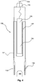
- Figures 1 and 2 both show a first embodiment of the oil/gas well fishing tool 60 provided according to the present application, whereas figure 3 shows an alternative embodiment of the fishing tool 70.
- fishing tools such as those shown, are employed to retrieve objects that either fall into a well or cannot be retrieved by using their normal retrieval method - for instance a tool attached to a snapped wire line or cable.
- the tool comprises an open-ended receptacle 61 with means 62 for engaging a deployment tool, such as wire line 63, so that the fishing tool 60 can be deployed down a well.
- a deployment tool such as wire line 63
- the receptacle is substantially 'bell-shaped'.
- alternative open-end receptacle shapes such as boxes and cylinders, could also be employed without departing from the scope of the present invention
- the alloy is preferably a eutectic alloy, although other non-eutectic alloys formed from bismuth are also considered applicable without departing from the general scope of the present invention.
- the tool is also provided with heating means, which in the shown embodiment comprise a layer of chemical heat source 65 (e.g. thermite) provided between the inner surface of the receptacle 61 and the layer of alloy 64.
- heating means which in the shown embodiment comprise a layer of chemical heat source 65 (e.g. thermite) provided between the inner surface of the receptacle 61 and the layer of alloy 64.
- the tool is further provided with ignition means 66, which can be activated via the wire line 63 to trigger the chemical heater and melt the alloy.
- the fishing tool 60 is delivered down a well 67 towards the stranded object (e.g. wrench 68) using, in this example, a wire line 63.
- the stranded object e.g. wrench 68
- the heating means are activated for a short period of time to cause the alloy located within the receptacle to melt and sag. As the alloy melts it comes into contact with the object and flows around it. As the heat source has already started to cool the alloy is itself beginning to cool down and solidify.
- the alloy 64 may have fragments of a second material embedded within it.
- a second material which is preferably a metal, has a higher melting point that the alloy so that it remains in its solid state when the alloy flows.
- the fragments which might be in the form of fibres or chips, enhance the gripping of the object by the alloy as it solidifies.
- the tool is provided with means 72 for engaging a deployment tool.
- FIG. 4 shows a further alternative embodiment of the fishing tool of the present invention.
- the fishing tool 150 is provided with a receptacle that is comprised of two parts, a main body 151 and a removable foot portion 152.
- the foot portion 152 can be connected to the main body 151 by a screw thread, although alternative means may also be used without departing from the claimed invention.
- the main body 151 of the receptacle is provided with means for engaging a deployment tool 153.
- a wire line 154 which attaches the fishing tool 151 to a deployment tool (not shown) located above ground, is also shown in part.
- a heater 155 Located within the main body 151 of the receptacle is a heater 155, which is housed with a mandrel 156.
- the eutectic/bismuth alloy 157 is provided on the surface of the mandrel 156. It is been discovered that by providing clearance between the main body 151 and the alloy 157 it enables the down hole fluids to circulate within the receptacle, which aids the flow of the melted alloy.
- the mandrel 156 which in the shown embodiment is located concentric to and entirely within the main body 151, is made from a material with a higher melting point than the alloy 157, suitable examples of which include steel and aluminium. This is also the case for the main body 151 and the foot portion 152.
- the foot portion 152 is provided with gripping means 158, in the form of a threaded region. It is envisaged that alternative types of gripping means, such as a roughened surface or a plurality of projections, might be used instead.
- gripping means such as a roughened surface or a plurality of projections.
- One key feature of the embodiment shown in figure 4 is that the foot portion 152 of the receptacle is detachable from the main body 151 of the receptacle. It is envisaged that this facility allows for a range of different shaped foot portions to be attached to the main body to suit the shape/size of the stranded object 160.
- the present application therefore also provide a method of assessing the size and shape of the stranded object in order to select a suitable foot portion for a particular task. It is appreciated that by having the main components of the fishing tool provided by a standard tool that is connectable to a variety of more tailored foot portions, it is possible to greatly reduce the costs involved in retrieving stranded objects from down a well. It is appreciated that some variants of the foot portion may be provided with one or more spear members similar to those shown in figure 3 .
Landscapes
- Engineering & Computer Science (AREA)
- Life Sciences & Earth Sciences (AREA)
- Geology (AREA)
- Mining & Mineral Resources (AREA)
- Environmental & Geological Engineering (AREA)
- Fluid Mechanics (AREA)
- Physics & Mathematics (AREA)
- General Life Sciences & Earth Sciences (AREA)
- Geochemistry & Mineralogy (AREA)
- Mechanical Engineering (AREA)
- Marine Sciences & Fisheries (AREA)
- Earth Drilling (AREA)
- Pipe Accessories (AREA)
- Consolidation Of Soil By Introduction Of Solidifying Substances Into Soil (AREA)
- Auxiliary Devices For Machine Tools (AREA)
Description
- The present invention relates to a downhole fishing tool, and in particular a fishing tool for use in retrieving objects that have become stranded within an oil or gas well.
- In order to access oil and gas deposits located in underground formations it is necessary to drill bore holes into these underground formation and deploy production tubing to facilitate the extraction of the oil and gas deposits.
- Additional tubing, in the form of well lining or well casing, may also deployed in locations where the underground formation is unstable and needs to held back to maintain the integrity of the oil/gas well.
- From time to time during the formation, completion and closure of oil and gas wells objects can become stranded within the well. Such objects can include: hand tools (e.g. wrenches); downhole tools; or parts of the casing that have become disconnected from the main casing body.
- Due to the limited access available within oil/gas wells, which are generally formed in deep underground formations stranded objects, such as those identified, can obstruct the passage of working equipment through the well and disrupt normal operations. Any disruption to the operation of an oil/gas well can be expensive due to a halt in the extraction of oil/gas.
- When objects become stranded downhole fishing tools can be employed to retrieve them from within the well as quickly as possible so that normal operations can be resumed promptly.
- However due to the distance between the operator, at the surface, and the stranded object deep within the well the process of fishing the object out can be challenging and time consuming. Also the equipment need for the fishing exercise is expensive.
-
US 2,789,004 A , which is considered the closest prior art, describes a fishing tool for retrieving iron or steel objects which are located within a well, such as a gas or oil well.US 4,488,747 A also describes a fishing tool for retrieving objects from a well, well bore, casing, and the like.US 3,871,315 A describes a tool for retrieving metal objects. - The present invention seeks to provide an improved fishing tool that quickly and effectively retrieve stranded objects from downhole locations, and in particular oil and gas wells.
- To this end there is provided an oil or gas well fishing tool, said tool comprising: a receptacle that is open at one end; deployment tool engaging means, located on the opposite end of the receptacle to the one end; a eutectic alloy and/or a bismuth based alloy provided within the interior of the receptacle; and heating means to heat the alloy so that it melts.
- In the use the fishing tool can be delivered down a well by suitable delivery means (e.g. wire line or coil tubing). The open-ended receptacle of the fishing tool enables the tool to surround the stranded object - which might typically be a tool, such as a wrench, broken downhole tool, damaged fishing neck or a piece of junk.
- Once in place on the object the heating means can be operated to heat the layer of alloy provided on the interior of the receptacle for a limited time. This causes the alloy to sag and flow over the object. When the alloy cools it binds the object to the fishing tool, thus enabling the object to be extracted from the well along with the fishing tool.
- Preferably the alloy may be provided as a layer of alloy on an interior surface of the receptacle.
- Preferably the heating means comprise an ignition means and a layer of a chemical heat source located between the receptacle and the alloy layer. Although alternative heat sources can be employed a chemical heat source, such as thermite, is considered particularly suitable as it enables the fishing tool to be a self-contained unit that does not require an external power source.
- Advantageously the fishing tool may further be provided with a spear member located within the receptacle. Further preferably the spear member extends beyond the open-end of the receptacle.
- The spear member provides an additional gripping functionality when using the fishing tool to retrieve snapped cable or wireline, for example.
- Preferably the receptacle of the fishing tool is substantially bell-shaped.
- Alternatively the receptacle may be formed by a combination of a main body and foot section. Further preferably the heating means and the alloy is provided within the main body of the receptacle.
- In addition the foot section may comprise additional gripping means. The additional gripping means may take the form of a roughened surface or a surface with a plurality of projections.
- Further preferably the foot section may be removable from the main body of the receptacle. In this way it is envisioned that a standard tool might be adapted to form a fishing tool be attaching the foot section to an off-the-shelf tool with an alloy and a heater.
Preferably the alloy has fragments of a second material embedded within it, wherein the melting temperature of the second material is higher that the alloy. In this way the second material can further enhance the gripping effect on the object achieved when the alloy cools. Preferably the second material is a metal or an alloy. - Further preferably the fragments are in the form of fibres or chips.
- The present invention also provides a method of retrieving an object lost down an oil or gas well, said method comprising: delivering the fishing tool of the present invention down a well so that it surrounds at least part of the lost object; heating the alloy within the fishing tool and allowing it flow over the object; allowing the alloy to cool before retrieving the fishing tool and the object from the well.
- Preferred embodiments of the present application will now be described with reference to the drawings, wherein:
-
Figure 1 shows a diagrammatic cross-sectional representation of an embodiment of the fishing tool provided by the present application; -
Figure 2 shows a diagrammatic representation of the key stages of the deployment and operation of the embodiment of the fishing tool offigure 1 ; -
Figure 3 shows an alternative embodiment of the fishing tool provided by the present application; and -
Figure 4 shows a further alternative embodiment of the fishing tool provided by the present application. -
Figures 1 and2 both show a first embodiment of the oil/gaswell fishing tool 60 provided according to the present application, whereasfigure 3 shows an alternative embodiment of thefishing tool 70. - As described above fishing tools, such as those shown, are employed to retrieve objects that either fall into a well or cannot be retrieved by using their normal retrieval method - for instance a tool attached to a snapped wire line or cable.
- As can be seen from the cross-sectional view of the
tool 60 provided infigure 1 , the tool comprises an open-ended receptacle 61 withmeans 62 for engaging a deployment tool, such aswire line 63, so that thefishing tool 60 can be deployed down a well. In the preferred embodiment the receptacle is substantially 'bell-shaped'. However alternative open-end receptacle shapes, such as boxes and cylinders, could also be employed without departing from the scope of the present invention - Located within the inside of the receptacle is a layer of an
alloy 64. The alloy is preferably a eutectic alloy, although other non-eutectic alloys formed from bismuth are also considered applicable without departing from the general scope of the present invention. - In order to heat the alloy when needed the tool is also provided with heating means, which in the shown embodiment comprise a layer of chemical heat source 65 (e.g. thermite) provided between the inner surface of the
receptacle 61 and the layer ofalloy 64. The tool is further provided with ignition means 66, which can be activated via thewire line 63 to trigger the chemical heater and melt the alloy. - In order to further explain the operation of the
fishing tool 60 reference is now made tofigure 2 , which show the key stages of the tool's operation. - In the first stage the
fishing tool 60 is delivered down a well 67 towards the stranded object (e.g. wrench 68) using, in this example, awire line 63. - Once the receptacle of the
tool 60 has be positioned about at least a portion of theobject 68 the heating means are activated for a short period of time to cause the alloy located within the receptacle to melt and sag. As the alloy melts it comes into contact with the object and flows around it. As the heat source has already started to cool the alloy is itself beginning to cool down and solidify. - As the alloy returns to its solid form the
object 68 becomes embedded within thesolid alloy 64 and in doing so becomes one with thefishing tool 60. The mergedfishing tool 60 andobject 68 can then be extracted from the well using thewire line 63. - Preferably, although not shown in the figures, the
alloy 64 may have fragments of a second material embedded within it. Such material, which is preferably a metal, has a higher melting point that the alloy so that it remains in its solid state when the alloy flows. In this way the fragments, which might be in the form of fibres or chips, enhance the gripping of the object by the alloy as it solidifies. - The
fishing tool 70 shown in figure 15 is further enhanced by the addition of aspear member 73 which projects from within the open-endedreceptacle 71. Thespear member 73, which is provided withtines 74 for enhanced gripping, is considered particularly suitable for retrieving snapped wire line and cable from within a well. - Once again the tool is provided with
means 72 for engaging a deployment tool. -
Figure 4 shows a further alternative embodiment of the fishing tool of the present invention. Thefishing tool 150 is provided with a receptacle that is comprised of two parts, amain body 151 and a removable foot portion 152. The foot portion 152 can be connected to themain body 151 by a screw thread, although alternative means may also be used without departing from the claimed invention. - The
main body 151 of the receptacle is provided with means for engaging adeployment tool 153. Infigure 4 awire line 154, which attaches thefishing tool 151 to a deployment tool (not shown) located above ground, is also shown in part. - Located within the
main body 151 of the receptacle is aheater 155, which is housed with amandrel 156. The eutectic/bismuth alloy 157 is provided on the surface of themandrel 156. It is been discovered that by providing clearance between themain body 151 and thealloy 157 it enables the down hole fluids to circulate within the receptacle, which aids the flow of the melted alloy. - The
mandrel 156, which in the shown embodiment is located concentric to and entirely within themain body 151, is made from a material with a higher melting point than thealloy 157, suitable examples of which include steel and aluminium. This is also the case for themain body 151 and the foot portion 152. - The foot portion 152 is provided with
gripping means 158, in the form of a threaded region. It is envisaged that alternative types of gripping means, such as a roughened surface or a plurality of projections, might be used instead. One key feature of the embodiment shown infigure 4 is that the foot portion 152 of the receptacle is detachable from themain body 151 of the receptacle. It is envisaged that this facility allows for a range of different shaped foot portions to be attached to the main body to suit the shape/size of the strandedobject 160. - The present application therefore also provide a method of assessing the size and shape of the stranded object in order to select a suitable foot portion for a particular task.
It is appreciated that by having the main components of the fishing tool provided by a standard tool that is connectable to a variety of more tailored foot portions, it is possible to greatly reduce the costs involved in retrieving stranded objects from down a well.
It is appreciated that some variants of the foot portion may be provided with one or more spear members similar to those shown infigure 3 .
Claims (15)
- An oil or gas well fishing tool 960, 70, 150), said tool comprising:a receptacle (61, 71) that is open at one end;deployment tool engaging means (62, 72, 153), located on the opposite end of the receptacle to the one end;an alloy (64, 157) provided within the interior of the receptacle (61);heating means (65, 155) to heat the alloy so that it melts; andcharacterised in that the alloy is a eutectic alloy and/or bismuth alloy.
- The fishing tool of claim 1, wherein a layer of alloy (64, 157) is provided on an interior surface of the receptacle (61, 71).
- The fishing tool of claim 2, wherein the heating means (65, 155) comprise an ignition means (66) and a layer of a chemical heat source located between the receptacle and the alloy layer.
- The fishing tool of claim 1, 2 or 3, further comprising a spear member (73) located on or in the receptacle (71).
- The fishing tool of claim 4, wherein the spear member (73) extends beyond the open-end of the receptacle (71).
- The fishing tool of any of claims 2 to 5, wherein the receptacle (71) is substantially bell-shaped.
- The fishing tool of any of claims 1 to 5, wherein the receptacle is formed by a combination of a main body (151) and foot portion (152).
- The fishing tool of claim 7, wherein the heating means (155) and the alloy (157) are provided within the main body (151) of the receptacle.
- The fishing tool of claim 7 or 8, wherein the foot portion (152) comprises additional gripping means (158).
- The fishing tool of claim 7, 8 or 9, wherein the foot portion (152) is removable from the main body (151) of the receptacle.
- The fishing tool of any of the preceding claims, wherein the alloy (64, 157) has fragments of a second material embedded within it, wherein the melting temperature of the second material is higher than the alloy.
- The fishing tool of claim 11, wherein the second material is a metal or an alloy.
- The fishing to of claim 11 or 12, wherein the fragments are in the form of fibres or chips.
- A method of retrieving an object lost down a gas or oil well, said method comprising:a) delivering a fishing tool (60, 70, 150) according to any of claims 1 to 13 down a well so that it surrounds at least part of the lost object;b) heating the alloy (64, 157) within the fishing tool and allowing it flow over the object; andc) allowing the alloy to cool before retrieving the fishing tool and the object from the well.
- The method of claim 14, further comprising the steps of assessing the size and shape of the stranded object and then selecting a foot portion (152) suitable to retrieve the object.
Applications Claiming Priority (2)
| Application Number | Priority Date | Filing Date | Title |
|---|---|---|---|
| GBGB1414565.0A GB201414565D0 (en) | 2014-08-15 | 2014-08-15 | Methods and apparatus for use in oil and gas well completion |
| PCT/GB2015/052346 WO2016024121A1 (en) | 2014-08-15 | 2015-08-14 | A downhole fishing tool |
Publications (2)
| Publication Number | Publication Date |
|---|---|
| EP3126617A1 EP3126617A1 (en) | 2017-02-08 |
| EP3126617B1 true EP3126617B1 (en) | 2018-05-16 |
Family
ID=51662526
Family Applications (5)
| Application Number | Title | Priority Date | Filing Date |
|---|---|---|---|
| EP22198301.8A Active EP4130425B1 (en) | 2014-08-15 | 2015-08-14 | Methods and apparatus for use in oil and gas well completion |
| EP15753981.8A Active EP3126617B1 (en) | 2014-08-15 | 2015-08-14 | A downhole fishing tool |
| EP15753148.4A Active EP3180491B1 (en) | 2014-08-15 | 2015-08-14 | Methods and apparatus for use in oil and gas well completion |
| EP15753149.2A Active EP3180492B1 (en) | 2014-08-15 | 2015-08-14 | Downhole well tools and methods of using such |
| EP19172004.4A Active EP3578749B1 (en) | 2014-08-15 | 2015-08-14 | Downhole straddle tools |
Family Applications Before (1)
| Application Number | Title | Priority Date | Filing Date |
|---|---|---|---|
| EP22198301.8A Active EP4130425B1 (en) | 2014-08-15 | 2015-08-14 | Methods and apparatus for use in oil and gas well completion |
Family Applications After (3)
| Application Number | Title | Priority Date | Filing Date |
|---|---|---|---|
| EP15753148.4A Active EP3180491B1 (en) | 2014-08-15 | 2015-08-14 | Methods and apparatus for use in oil and gas well completion |
| EP15753149.2A Active EP3180492B1 (en) | 2014-08-15 | 2015-08-14 | Downhole well tools and methods of using such |
| EP19172004.4A Active EP3578749B1 (en) | 2014-08-15 | 2015-08-14 | Downhole straddle tools |
Country Status (8)
| Country | Link |
|---|---|
| US (7) | US10309187B2 (en) |
| EP (5) | EP4130425B1 (en) |
| CA (3) | CA2987496C (en) |
| DK (4) | DK3578749T3 (en) |
| GB (2) | GB201414565D0 (en) |
| NO (1) | NO3126617T3 (en) |
| SA (2) | SA517380902B1 (en) |
| WO (3) | WO2016024123A1 (en) |
Families Citing this family (31)
| Publication number | Priority date | Publication date | Assignee | Title |
|---|---|---|---|---|
| GB2480869B (en) | 2010-06-04 | 2017-01-11 | Bisn Tec Ltd | Method and apparatus for use in well abandonment |
| GB201223055D0 (en) | 2012-12-20 | 2013-02-06 | Carragher Paul | Method and apparatus for use in well abandonment |
| GB201406071D0 (en) | 2014-04-04 | 2014-05-21 | Bisn Tec Ltd | Well Casing / Tubing Disposal |
| GB201414565D0 (en) | 2014-08-15 | 2014-10-01 | Bisn Oil Tools Ltd | Methods and apparatus for use in oil and gas well completion |
| GB2549982B (en) | 2016-05-06 | 2019-10-30 | Bisn Tec Ltd | Heat sources and alloys for use in down-hole operations |
| WO2018215786A1 (en) * | 2017-05-24 | 2018-11-29 | Bisn Tec Ltd | A downhole tool deployment assembly with improved heater removability and methods of employing such |
| GB2551693B (en) * | 2016-05-24 | 2021-09-15 | Bisn Tec Ltd | Down-hole chemical heater and methods of operating such |
| MY203147A (en) * | 2016-08-19 | 2024-06-11 | Bisn Tec Ltd | Downhole operations relating to open hole gravel packs and tools for use therein |
| GB2562208B (en) * | 2017-04-04 | 2021-04-07 | Bisn Tec Ltd | Improvements relating to thermally deformable annular packers |
| US11365611B2 (en) * | 2017-05-01 | 2022-06-21 | Conocophillips Company | Metal seal for liner drilling |
| CA3070391C (en) * | 2017-06-29 | 2024-01-02 | Conocophillips Company | Methods, systems, and devices for sealing stage tool leaks |
| GB2568519B (en) | 2017-11-17 | 2022-09-28 | Bisn Tec Ltd | An expandable eutectic alloy based downhole tool and methods of deploying such |
| US10844699B2 (en) * | 2018-05-29 | 2020-11-24 | Saudi Arabian Oil Company | By-pass system and method for inverted ESP completion |
| US11846418B2 (en) * | 2018-12-28 | 2023-12-19 | Robertson Intellectual Properties, LLC | Protective material for fuel system |
| GB2583372B (en) | 2019-04-26 | 2022-03-02 | Isol8 Holdings Ltd | Downhole sealing methods and apparatus |
| US10975658B2 (en) | 2019-05-17 | 2021-04-13 | Baker Hughes Oilfield Operations Llc | Wellbore isolation barrier including negative thermal expansion material |
| NO20210121A1 (en) * | 2020-02-10 | 2021-08-11 | Wellbore Integrity Solutions Llc | Patch for joining downhole ends of pipes |
| US12123278B2 (en) | 2020-06-22 | 2024-10-22 | Bisn Tec Ltd. | Plug with composite ends and method of forming and using |
| US11448034B2 (en) | 2020-07-13 | 2022-09-20 | Saudi Arabian Oil Company | Removable plugging method and apparatus |
| US12305485B2 (en) | 2020-07-15 | 2025-05-20 | Conocophillips Company | Well collapse reconnect method |
| CN112096336A (en) * | 2020-09-07 | 2020-12-18 | 深圳百途石油技术服务有限公司 | Method and device for treating annulus under pressure of gas well |
| GB202111796D0 (en) | 2021-08-17 | 2021-09-29 | Bisn Tec Ltd | A downhole external catch tool and methods of using such |
| GB2612622A (en) | 2021-11-05 | 2023-05-10 | Bisn Tec Ltd | A chemical reaction heat source composition for use in downhole operations and associated apparatus and methods |
| EP4519535A1 (en) | 2022-05-04 | 2025-03-12 | BiSN Tec Ltd | Methods to remove alloy plugs and annular seals and associated apparatus |
| US12312914B2 (en) * | 2022-12-26 | 2025-05-27 | Dbk Industries, Llc | Bulkhead igniter with snap-on insulator |
| US12037870B1 (en) | 2023-02-10 | 2024-07-16 | Newpark Drilling Fluids Llc | Mitigating lost circulation |
| US12241336B2 (en) | 2023-07-17 | 2025-03-04 | Weatherford Technology Holdings, Llc | Control of annulus return flow in well operations |
| US12320220B2 (en) | 2023-09-14 | 2025-06-03 | Saudi Arabian Oil Company | Laser cladding fishing tool |
| US12338700B2 (en) | 2023-09-14 | 2025-06-24 | Saudi Arabian Oil Company | Powder weld fishing tool |
| US12228010B1 (en) * | 2024-01-05 | 2025-02-18 | Saudi Arabian Oil Company | Eutectic alloy system for casing-casing annulus cement repair |
| US12352118B1 (en) | 2024-01-10 | 2025-07-08 | Saudi Arabian Oil Company | Method and apparatus for delivering and setting a eutectic alloy plug to cure loss-of-circulation in drilling applications |
Family Cites Families (81)
| Publication number | Priority date | Publication date | Assignee | Title |
|---|---|---|---|---|
| US1534229A (en) | 1924-07-12 | 1925-04-21 | Gerald R Livergood | Fishing tool |
| US2076308A (en) | 1936-02-15 | 1937-04-06 | Technicraft Engineering Corp | Well heating device and method |
| US2686689A (en) | 1950-04-29 | 1954-08-17 | Pyke Herbert Douglas | Method and apparatus for retrieving junk from well bores |
| US2789004A (en) | 1954-03-17 | 1957-04-16 | Henry C Foster | Metal fishing tool |
| US2780294A (en) * | 1955-05-02 | 1957-02-05 | John Stahl | Packer assembly |
| US2822876A (en) | 1955-10-26 | 1958-02-11 | M & M Mfg Company Inc | Deep well bridge |
| US2942668A (en) * | 1957-11-19 | 1960-06-28 | Union Oil Co | Well plugging, packing, and/or testing tool |
| US3119451A (en) | 1961-01-09 | 1964-01-28 | John A Hall | Cement basket |
| US3170516A (en) | 1962-06-25 | 1965-02-23 | Jersey Prod Res Co | Method of plugging a well bore with a thermosetting resin |
| US3208530A (en) | 1964-09-14 | 1965-09-28 | Exxon Production Research Co | Apparatus for setting bridge plugs |
| US3871315A (en) | 1973-06-20 | 1975-03-18 | Leonard Morgansen Andersen | Device for salvaging metal objects and salvaging method |
| US4134452A (en) | 1977-09-14 | 1979-01-16 | Gulf Research & Development Company | Well testing tool |
| DE2809181B2 (en) | 1978-03-03 | 1980-07-24 | Guenter 4520 Melle Kreft | Safety centering basket |
| US4270761A (en) * | 1979-12-03 | 1981-06-02 | Seals Eastern Inc. | Seal for geothermal wells and the like |
| GB2164886A (en) | 1981-02-23 | 1986-04-03 | Hot Hed Inc | Welding preheating insert for heavy wall pipe |
| US4423783A (en) | 1982-04-23 | 1984-01-03 | Texaco Inc. | Method for plugging a well and bridge plug |
| US4488747A (en) * | 1982-08-12 | 1984-12-18 | George Austin | Method and fishing tool apparatus for recovering objects from wells |
| US4487747A (en) * | 1983-05-05 | 1984-12-11 | Laporte Industries Limited | Production of metal chlorides |
| US4523640A (en) | 1984-01-23 | 1985-06-18 | Dresser Industries, Inc. | Arm release system for well logging apparatus |
| US4696343A (en) | 1986-05-23 | 1987-09-29 | S.I.E., Inc. | Wireline dump bailer |
| US5052489A (en) | 1990-06-15 | 1991-10-01 | Carisella James V | Apparatus for selectively actuating well tools |
| US5564861A (en) | 1995-06-06 | 1996-10-15 | Khudenko; Boris M. | Thermal method of in-situ soil treatment |
| US5833001A (en) | 1996-12-13 | 1998-11-10 | Schlumberger Technology Corporation | Sealing well casings |
| US6474414B1 (en) | 2000-03-09 | 2002-11-05 | Texaco, Inc. | Plug for tubulars |
| US6828531B2 (en) | 2000-03-30 | 2004-12-07 | Homer L. Spencer | Oil and gas well alloy squeezing method and apparatus |
| US6664522B2 (en) | 2000-03-30 | 2003-12-16 | Homer L. Spencer | Method and apparatus for sealing multiple casings for oil and gas wells |
| US6454001B1 (en) | 2000-05-12 | 2002-09-24 | Halliburton Energy Services, Inc. | Method and apparatus for plugging wells |
| US7455104B2 (en) * | 2000-06-01 | 2008-11-25 | Schlumberger Technology Corporation | Expandable elements |
| GB0023543D0 (en) | 2000-09-26 | 2000-11-08 | Rawwater Engineering Company L | Sealing method and apparatus |
| NO335594B1 (en) | 2001-01-16 | 2015-01-12 | Halliburton Energy Serv Inc | Expandable devices and methods thereof |
| GB0108384D0 (en) | 2001-04-04 | 2001-05-23 | Weatherford Lamb | Bore-lining tubing |
| MY130896A (en) * | 2001-06-05 | 2007-07-31 | Shell Int Research | In-situ casting of well equipment |
| GB0207371D0 (en) * | 2002-03-28 | 2002-05-08 | Rawwater Engineering Company L | Sealing method and apparatus |
| US6766858B2 (en) * | 2002-12-04 | 2004-07-27 | Halliburton Energy Services, Inc. | Method for managing the production of a well |
| US7048048B2 (en) | 2003-06-26 | 2006-05-23 | Halliburton Energy Services, Inc. | Expandable sand control screen and method for use of same |
| GB2442636B (en) * | 2004-01-12 | 2008-10-08 | Shell Oil Co | Expandable connection |
| US7055595B2 (en) * | 2004-04-02 | 2006-06-06 | Baker Hughes Incorporated | Electrical submersible pump actuated packer |
| US7290609B2 (en) | 2004-08-20 | 2007-11-06 | Cinaruco International S.A. Calle Aguilino De La Guardia | Subterranean well secondary plugging tool for repair of a first plug |
| US20060144591A1 (en) | 2004-12-30 | 2006-07-06 | Chevron U.S.A. Inc. | Method and apparatus for repair of wells utilizing meltable repair materials and exothermic reactants as heating agents |
| US7934552B2 (en) | 2005-09-08 | 2011-05-03 | Thomas La Rovere | Method and apparatus for well casing repair and plugging utilizing molten metal |
| US8151895B1 (en) * | 2006-02-17 | 2012-04-10 | Baker Hughes Incorporated | Eutectic salt inflated wellbore tubular patch |
| CA2579116C (en) * | 2006-02-17 | 2011-09-20 | Innicor Subsurface Technologies Inc. | Eutectic material-based seal element for packers |
| US20080047708A1 (en) * | 2006-06-24 | 2008-02-28 | Spencer Homer L | Method and apparatus for plugging perforations |
| EP1933004A1 (en) | 2006-12-12 | 2008-06-18 | Shell Internationale Researchmaatschappij B.V. | Method of controlling hardening of a compound in a wellbore |
| US8327926B2 (en) | 2008-03-26 | 2012-12-11 | Robertson Intellectual Properties, LLC | Method for removing a consumable downhole tool |
| US20100006289A1 (en) | 2008-05-13 | 2010-01-14 | Spencer Homer L | Method and apparatus for sealing abandoned oil and gas wells |
| US7841417B2 (en) | 2008-11-24 | 2010-11-30 | Halliburton Energy Services, Inc. | Use of swellable material in an annular seal element to prevent leakage in a subterranean well |
| US20100263876A1 (en) | 2009-04-21 | 2010-10-21 | Frazier W Lynn | Combination down hole tool |
| EP2243920A1 (en) * | 2009-04-22 | 2010-10-27 | Tenaris Connections Aktiengesellschaft | Threaded joint for tubes, pipes and the like |
| US20110155377A1 (en) * | 2009-06-29 | 2011-06-30 | Laun Lyle E | Joint or coupling device incorporating a mechanically-induced weak point and method of use |
| US20110036570A1 (en) * | 2009-08-14 | 2011-02-17 | La Rovere Thomas A | Method and apparatus for well casing shoe seal |
| US8297368B2 (en) * | 2009-10-28 | 2012-10-30 | Chevron U.S.A. Inc. | Systems and methods for initiating annular obstruction in a subsurface well |
| US8191644B2 (en) * | 2009-12-07 | 2012-06-05 | Schlumberger Technology Corporation | Temperature-activated swellable wellbore completion device and method |
| US8196515B2 (en) | 2009-12-09 | 2012-06-12 | Robertson Intellectual Properties, LLC | Non-explosive power source for actuating a subsurface tool |
| CA2688704C (en) | 2009-12-15 | 2016-04-26 | Rawwater Engineering Company Limited | Sealing method and apparatus |
| US8685187B2 (en) | 2009-12-23 | 2014-04-01 | Schlumberger Technology Corporation | Perforating devices utilizing thermite charges in well perforation and downhole fracing |
| US8839871B2 (en) | 2010-01-15 | 2014-09-23 | Halliburton Energy Services, Inc. | Well tools operable via thermal expansion resulting from reactive materials |
| EP2362062A1 (en) | 2010-02-22 | 2011-08-31 | Welltec A/S | An annular barrier |
| EA201201632A1 (en) | 2010-05-31 | 2013-04-30 | Юнилевер Н.В. | COMPOSITION FOR SKIN CARE |
| GB2480869B (en) | 2010-06-04 | 2017-01-11 | Bisn Tec Ltd | Method and apparatus for use in well abandonment |
| GB2485811B (en) * | 2010-11-25 | 2017-09-20 | M-I Drilling Fluids U K Ltd | Downhole tool and method |
| SG190713A1 (en) * | 2010-12-17 | 2013-07-31 | Exxonmobil Upstream Res Co | Wellbore apparatus and methods for multi-zone well completion, production and injection |
| EP2773841B1 (en) | 2011-11-04 | 2016-11-02 | Halliburton Energy Services, Inc. | Methods of severing an object from the outside using heat evolved from an exothermic reaction |
| US9534701B2 (en) | 2012-02-01 | 2017-01-03 | Halliburton Energy Services, Inc. | Opening or closing a fluid flow path using a material that expands or contracts via a change in temperature |
| WO2013184237A1 (en) * | 2012-06-04 | 2013-12-12 | Exxonmobil Upstream Research Company | Wellbore assembly for injecting a fluid into a subsurface formation, and method of injecting fluids into a subsurface formation |
| NO337410B1 (en) * | 2012-07-23 | 2016-04-11 | Plugtech As | Plug for temporary installation in a well |
| GB201223055D0 (en) | 2012-12-20 | 2013-02-06 | Carragher Paul | Method and apparatus for use in well abandonment |
| US9790755B2 (en) | 2013-04-24 | 2017-10-17 | Halliburton Energy Services, Inc. | Positive displacement dump bailer and method of operation |
| BR112015029317B1 (en) * | 2013-05-22 | 2021-11-30 | Fmc Kongsberg Subsea As | SEALING ELEMENT, METHOD FOR MANUFACTURING A SEALING ELEMENT AND METHOD FOR SEALING A PRESSURE RETENTION SYSTEM |
| US9447655B2 (en) * | 2013-10-15 | 2016-09-20 | Baker Hughes Incorporated | Methods for hanging liner from casing and articles derived therefrom |
| US20150211328A1 (en) | 2014-01-30 | 2015-07-30 | Olympic Research, Inc. | Well sealing via thermite reactions |
| US20150211327A1 (en) | 2014-01-30 | 2015-07-30 | Olympic Research, Inc. | Well sealing via thermite reactions |
| US9228412B2 (en) | 2014-01-30 | 2016-01-05 | Olympic Research, Inc. | Well sealing via thermite reactions |
| GB201406071D0 (en) | 2014-04-04 | 2014-05-21 | Bisn Tec Ltd | Well Casing / Tubing Disposal |
| GB201414565D0 (en) | 2014-08-15 | 2014-10-01 | Bisn Oil Tools Ltd | Methods and apparatus for use in oil and gas well completion |
| EP3029261B1 (en) | 2014-12-02 | 2019-05-22 | Services Pétroliers Schlumberger | Methods of deployment for eutectic isolation tools to ensure wellbore plugs |
| US20170251231A1 (en) | 2015-01-05 | 2017-08-31 | Gitcirrus, Llc | System and Method for Media Synchronization and Collaboration |
| US10352109B2 (en) * | 2015-05-20 | 2019-07-16 | Schlumberger Technology Corporation | System and methodology for coupling tubing |
| GB2551693B (en) | 2016-05-24 | 2021-09-15 | Bisn Tec Ltd | Down-hole chemical heater and methods of operating such |
| GB2562208B (en) | 2017-04-04 | 2021-04-07 | Bisn Tec Ltd | Improvements relating to thermally deformable annular packers |
| US11365611B2 (en) * | 2017-05-01 | 2022-06-21 | Conocophillips Company | Metal seal for liner drilling |
-
2014
- 2014-08-15 GB GBGB1414565.0A patent/GB201414565D0/en not_active Ceased
-
2015
- 2015-04-02 GB GB1505750.8A patent/GB2529275B/en active Active
- 2015-08-14 CA CA2987496A patent/CA2987496C/en active Active
- 2015-08-14 US US15/309,789 patent/US10309187B2/en active Active
- 2015-08-14 NO NO15753981A patent/NO3126617T3/no unknown
- 2015-08-14 WO PCT/GB2015/052348 patent/WO2016024123A1/en active Application Filing
- 2015-08-14 DK DK19172004.4T patent/DK3578749T3/en active
- 2015-08-14 DK DK15753148.4T patent/DK3180491T3/en active
- 2015-08-14 US US15/502,960 patent/US10961806B2/en active Active
- 2015-08-14 US US15/502,966 patent/US10370931B2/en active Active
- 2015-08-14 CA CA2987546A patent/CA2987546C/en active Active
- 2015-08-14 WO PCT/GB2015/052347 patent/WO2016024122A2/en active Application Filing
- 2015-08-14 CA CA2987506A patent/CA2987506C/en active Active
- 2015-08-14 EP EP22198301.8A patent/EP4130425B1/en active Active
- 2015-08-14 EP EP15753981.8A patent/EP3126617B1/en active Active
- 2015-08-14 WO PCT/GB2015/052346 patent/WO2016024121A1/en active Application Filing
- 2015-08-14 EP EP15753148.4A patent/EP3180491B1/en active Active
- 2015-08-14 DK DK15753149.2T patent/DK3180492T3/en active
- 2015-08-14 EP EP15753149.2A patent/EP3180492B1/en active Active
- 2015-08-14 EP EP19172004.4A patent/EP3578749B1/en active Active
- 2015-08-14 DK DK15753981.8T patent/DK3126617T3/en active
-
2017
- 2017-02-14 SA SA517380902A patent/SA517380902B1/en unknown
- 2017-02-14 SA SA517380901A patent/SA517380901B1/en unknown
-
2019
- 2019-06-02 US US16/429,037 patent/US11053771B2/en active Active
- 2019-08-05 US US16/531,331 patent/US11492870B2/en active Active
-
2021
- 2021-03-29 US US17/216,595 patent/US12084942B2/en active Active
- 2021-07-04 US US17/367,376 patent/US11525326B2/en active Active
Non-Patent Citations (1)
| Title |
|---|
| None * |
Also Published As
Similar Documents
| Publication | Publication Date | Title |
|---|---|---|
| US11525326B2 (en) | Downhole fishing tool | |
| US11536111B2 (en) | Downhole tool deployment assembly with improved heater removability and methods of employing such | |
| US10240420B2 (en) | Method for recovering tubular structures from a well and a downhole tool string | |
| RU2656643C2 (en) | Determining stuck point of tubing in wellbore | |
| US11306547B2 (en) | Systems and methods for releasing a tool string | |
| Тalalay et al. | Ice-core drilling problems and solutions | |
| EP3070261A2 (en) | Wellbore mill having shear cutters and gouging cutters | |
| US7600581B2 (en) | Downhole abrading tools having fusible material and uses therefor | |
| US11692442B2 (en) | Safety system and method for protecting against a hazard of drill rod failure in a drilled rock bore | |
| CN105880545A (en) | Method for exchangeably fastening a refractory purge plug or sleeve and a container for molten metal | |
| CN103147712A (en) | Casing milling fishing collar for short and light fell articles | |
| EP3631150B1 (en) | A downhole tool deployment assembly with improved heater removability and methods of employing such | |
| US20130175044A1 (en) | Retrievable subsea device and method | |
| AU2010249527B2 (en) | Auxiliary conduit cutting apparatus | |
| US2551995A (en) | Rotary core drill with jar mechanism | |
| US7828062B2 (en) | Downhole tool | |
| US3187238A (en) | Magnetic bell nipple | |
| US20250198248A1 (en) | Methods and apparatuses for removing metal objects from wells | |
| US20120160477A1 (en) | Large bore jar for a drill string | |
| WO2016069596A1 (en) | Eutectic casing window | |
| US20190218876A1 (en) | Downhole tool string | |
| US1154483A (en) | Drill-jar. | |
| AU608014B2 (en) | Release coupling |
Legal Events
| Date | Code | Title | Description |
|---|---|---|---|
| PUAI | Public reference made under article 153(3) epc to a published international application that has entered the european phase |
Free format text: ORIGINAL CODE: 0009012 |
|
| 17P | Request for examination filed |
Effective date: 20161027 |
|
| AK | Designated contracting states |
Kind code of ref document: A1 Designated state(s): AL AT BE BG CH CY CZ DE DK EE ES FI FR GB GR HR HU IE IS IT LI LT LU LV MC MK MT NL NO PL PT RO RS SE SI SK SM TR |
|
| AX | Request for extension of the european patent |
Extension state: BA ME |
|
| DAV | Request for validation of the european patent (deleted) | ||
| DAX | Request for extension of the european patent (deleted) | ||
| GRAP | Despatch of communication of intention to grant a patent |
Free format text: ORIGINAL CODE: EPIDOSNIGR1 |
|
| INTG | Intention to grant announced |
Effective date: 20171130 |
|
| GRAS | Grant fee paid |
Free format text: ORIGINAL CODE: EPIDOSNIGR3 |
|
| GRAA | (expected) grant |
Free format text: ORIGINAL CODE: 0009210 |
|
| AK | Designated contracting states |
Kind code of ref document: B1 Designated state(s): AL AT BE BG CH CY CZ DE DK EE ES FI FR GB GR HR HU IE IS IT LI LT LU LV MC MK MT NL NO PL PT RO RS SE SI SK SM TR |
|
| REG | Reference to a national code |
Ref country code: GB Ref legal event code: FG4D |
|
| REG | Reference to a national code |
Ref country code: CH Ref legal event code: EP |
|
| REG | Reference to a national code |
Ref country code: IE Ref legal event code: FG4D |
|
| REG | Reference to a national code |
Ref country code: DE Ref legal event code: R096 Ref document number: 602015011265 Country of ref document: DE |
|
| REG | Reference to a national code |
Ref country code: AT Ref legal event code: REF Ref document number: 999755 Country of ref document: AT Kind code of ref document: T Effective date: 20180615 |
|
| REG | Reference to a national code |
Ref country code: NO Ref legal event code: T2 Effective date: 20180516 |
|
| REG | Reference to a national code |
Ref country code: DK Ref legal event code: T3 Effective date: 20180814 |
|
| REG | Reference to a national code |
Ref country code: FR Ref legal event code: PLFP Year of fee payment: 4 |
|
| REG | Reference to a national code |
Ref country code: NL Ref legal event code: MP Effective date: 20180516 |
|
| REG | Reference to a national code |
Ref country code: LT Ref legal event code: MG4D |
|
| PG25 | Lapsed in a contracting state [announced via postgrant information from national office to epo] |
Ref country code: FI Free format text: LAPSE BECAUSE OF FAILURE TO SUBMIT A TRANSLATION OF THE DESCRIPTION OR TO PAY THE FEE WITHIN THE PRESCRIBED TIME-LIMIT Effective date: 20180516 Ref country code: LT Free format text: LAPSE BECAUSE OF FAILURE TO SUBMIT A TRANSLATION OF THE DESCRIPTION OR TO PAY THE FEE WITHIN THE PRESCRIBED TIME-LIMIT Effective date: 20180516 Ref country code: ES Free format text: LAPSE BECAUSE OF FAILURE TO SUBMIT A TRANSLATION OF THE DESCRIPTION OR TO PAY THE FEE WITHIN THE PRESCRIBED TIME-LIMIT Effective date: 20180516 Ref country code: SE Free format text: LAPSE BECAUSE OF FAILURE TO SUBMIT A TRANSLATION OF THE DESCRIPTION OR TO PAY THE FEE WITHIN THE PRESCRIBED TIME-LIMIT Effective date: 20180516 Ref country code: BG Free format text: LAPSE BECAUSE OF FAILURE TO SUBMIT A TRANSLATION OF THE DESCRIPTION OR TO PAY THE FEE WITHIN THE PRESCRIBED TIME-LIMIT Effective date: 20180816 |
|
| PG25 | Lapsed in a contracting state [announced via postgrant information from national office to epo] |
Ref country code: LV Free format text: LAPSE BECAUSE OF FAILURE TO SUBMIT A TRANSLATION OF THE DESCRIPTION OR TO PAY THE FEE WITHIN THE PRESCRIBED TIME-LIMIT Effective date: 20180516 Ref country code: RS Free format text: LAPSE BECAUSE OF FAILURE TO SUBMIT A TRANSLATION OF THE DESCRIPTION OR TO PAY THE FEE WITHIN THE PRESCRIBED TIME-LIMIT Effective date: 20180516 Ref country code: NL Free format text: LAPSE BECAUSE OF FAILURE TO SUBMIT A TRANSLATION OF THE DESCRIPTION OR TO PAY THE FEE WITHIN THE PRESCRIBED TIME-LIMIT Effective date: 20180516 Ref country code: GR Free format text: LAPSE BECAUSE OF FAILURE TO SUBMIT A TRANSLATION OF THE DESCRIPTION OR TO PAY THE FEE WITHIN THE PRESCRIBED TIME-LIMIT Effective date: 20180817 Ref country code: HR Free format text: LAPSE BECAUSE OF FAILURE TO SUBMIT A TRANSLATION OF THE DESCRIPTION OR TO PAY THE FEE WITHIN THE PRESCRIBED TIME-LIMIT Effective date: 20180516 |
|
| REG | Reference to a national code |
Ref country code: AT Ref legal event code: MK05 Ref document number: 999755 Country of ref document: AT Kind code of ref document: T Effective date: 20180516 |
|
| PG25 | Lapsed in a contracting state [announced via postgrant information from national office to epo] |
Ref country code: AT Free format text: LAPSE BECAUSE OF FAILURE TO SUBMIT A TRANSLATION OF THE DESCRIPTION OR TO PAY THE FEE WITHIN THE PRESCRIBED TIME-LIMIT Effective date: 20180516 Ref country code: PL Free format text: LAPSE BECAUSE OF FAILURE TO SUBMIT A TRANSLATION OF THE DESCRIPTION OR TO PAY THE FEE WITHIN THE PRESCRIBED TIME-LIMIT Effective date: 20180516 Ref country code: EE Free format text: LAPSE BECAUSE OF FAILURE TO SUBMIT A TRANSLATION OF THE DESCRIPTION OR TO PAY THE FEE WITHIN THE PRESCRIBED TIME-LIMIT Effective date: 20180516 Ref country code: SK Free format text: LAPSE BECAUSE OF FAILURE TO SUBMIT A TRANSLATION OF THE DESCRIPTION OR TO PAY THE FEE WITHIN THE PRESCRIBED TIME-LIMIT Effective date: 20180516 Ref country code: RO Free format text: LAPSE BECAUSE OF FAILURE TO SUBMIT A TRANSLATION OF THE DESCRIPTION OR TO PAY THE FEE WITHIN THE PRESCRIBED TIME-LIMIT Effective date: 20180516 Ref country code: CZ Free format text: LAPSE BECAUSE OF FAILURE TO SUBMIT A TRANSLATION OF THE DESCRIPTION OR TO PAY THE FEE WITHIN THE PRESCRIBED TIME-LIMIT Effective date: 20180516 |
|
| REG | Reference to a national code |
Ref country code: DE Ref legal event code: R097 Ref document number: 602015011265 Country of ref document: DE |
|
| PG25 | Lapsed in a contracting state [announced via postgrant information from national office to epo] |
Ref country code: SM Free format text: LAPSE BECAUSE OF FAILURE TO SUBMIT A TRANSLATION OF THE DESCRIPTION OR TO PAY THE FEE WITHIN THE PRESCRIBED TIME-LIMIT Effective date: 20180516 |
|
| PLBE | No opposition filed within time limit |
Free format text: ORIGINAL CODE: 0009261 |
|
| STAA | Information on the status of an ep patent application or granted ep patent |
Free format text: STATUS: NO OPPOSITION FILED WITHIN TIME LIMIT |
|
| PG25 | Lapsed in a contracting state [announced via postgrant information from national office to epo] |
Ref country code: MC Free format text: LAPSE BECAUSE OF FAILURE TO SUBMIT A TRANSLATION OF THE DESCRIPTION OR TO PAY THE FEE WITHIN THE PRESCRIBED TIME-LIMIT Effective date: 20180516 |
|
| REG | Reference to a national code |
Ref country code: CH Ref legal event code: PL |
|
| 26N | No opposition filed |
Effective date: 20190219 |
|
| PG25 | Lapsed in a contracting state [announced via postgrant information from national office to epo] |
Ref country code: CH Free format text: LAPSE BECAUSE OF NON-PAYMENT OF DUE FEES Effective date: 20180831 Ref country code: LU Free format text: LAPSE BECAUSE OF NON-PAYMENT OF DUE FEES Effective date: 20180814 Ref country code: LI Free format text: LAPSE BECAUSE OF NON-PAYMENT OF DUE FEES Effective date: 20180831 |
|
| REG | Reference to a national code |
Ref country code: BE Ref legal event code: MM Effective date: 20180831 |
|
| REG | Reference to a national code |
Ref country code: IE Ref legal event code: MM4A |
|
| PG25 | Lapsed in a contracting state [announced via postgrant information from national office to epo] |
Ref country code: SI Free format text: LAPSE BECAUSE OF FAILURE TO SUBMIT A TRANSLATION OF THE DESCRIPTION OR TO PAY THE FEE WITHIN THE PRESCRIBED TIME-LIMIT Effective date: 20180516 |
|
| PG25 | Lapsed in a contracting state [announced via postgrant information from national office to epo] |
Ref country code: IE Free format text: LAPSE BECAUSE OF NON-PAYMENT OF DUE FEES Effective date: 20180814 |
|
| PG25 | Lapsed in a contracting state [announced via postgrant information from national office to epo] |
Ref country code: BE Free format text: LAPSE BECAUSE OF NON-PAYMENT OF DUE FEES Effective date: 20180831 |
|
| PGFP | Annual fee paid to national office [announced via postgrant information from national office to epo] |
Ref country code: FR Payment date: 20190806 Year of fee payment: 5 Ref country code: IT Payment date: 20190820 Year of fee payment: 5 Ref country code: DE Payment date: 20190808 Year of fee payment: 5 |
|
| PG25 | Lapsed in a contracting state [announced via postgrant information from national office to epo] |
Ref country code: AL Free format text: LAPSE BECAUSE OF FAILURE TO SUBMIT A TRANSLATION OF THE DESCRIPTION OR TO PAY THE FEE WITHIN THE PRESCRIBED TIME-LIMIT Effective date: 20180516 |
|
| PG25 | Lapsed in a contracting state [announced via postgrant information from national office to epo] |
Ref country code: MT Free format text: LAPSE BECAUSE OF NON-PAYMENT OF DUE FEES Effective date: 20180814 |
|
| PG25 | Lapsed in a contracting state [announced via postgrant information from national office to epo] |
Ref country code: TR Free format text: LAPSE BECAUSE OF FAILURE TO SUBMIT A TRANSLATION OF THE DESCRIPTION OR TO PAY THE FEE WITHIN THE PRESCRIBED TIME-LIMIT Effective date: 20180516 |
|
| PG25 | Lapsed in a contracting state [announced via postgrant information from national office to epo] |
Ref country code: PT Free format text: LAPSE BECAUSE OF FAILURE TO SUBMIT A TRANSLATION OF THE DESCRIPTION OR TO PAY THE FEE WITHIN THE PRESCRIBED TIME-LIMIT Effective date: 20180516 |
|
| PG25 | Lapsed in a contracting state [announced via postgrant information from national office to epo] |
Ref country code: HU Free format text: LAPSE BECAUSE OF FAILURE TO SUBMIT A TRANSLATION OF THE DESCRIPTION OR TO PAY THE FEE WITHIN THE PRESCRIBED TIME-LIMIT; INVALID AB INITIO Effective date: 20150814 Ref country code: MK Free format text: LAPSE BECAUSE OF NON-PAYMENT OF DUE FEES Effective date: 20180516 Ref country code: CY Free format text: LAPSE BECAUSE OF FAILURE TO SUBMIT A TRANSLATION OF THE DESCRIPTION OR TO PAY THE FEE WITHIN THE PRESCRIBED TIME-LIMIT Effective date: 20180516 |
|
| PG25 | Lapsed in a contracting state [announced via postgrant information from national office to epo] |
Ref country code: IS Free format text: LAPSE BECAUSE OF FAILURE TO SUBMIT A TRANSLATION OF THE DESCRIPTION OR TO PAY THE FEE WITHIN THE PRESCRIBED TIME-LIMIT Effective date: 20180916 |
|
| REG | Reference to a national code |
Ref country code: DE Ref legal event code: R119 Ref document number: 602015011265 Country of ref document: DE |
|
| PG25 | Lapsed in a contracting state [announced via postgrant information from national office to epo] |
Ref country code: FR Free format text: LAPSE BECAUSE OF NON-PAYMENT OF DUE FEES Effective date: 20200831 Ref country code: DE Free format text: LAPSE BECAUSE OF NON-PAYMENT OF DUE FEES Effective date: 20210302 Ref country code: IT Free format text: LAPSE BECAUSE OF NON-PAYMENT OF DUE FEES Effective date: 20200814 |
|
| PGFP | Annual fee paid to national office [announced via postgrant information from national office to epo] |
Ref country code: DK Payment date: 20240829 Year of fee payment: 10 |
|
| PGFP | Annual fee paid to national office [announced via postgrant information from national office to epo] |
Ref country code: NO Payment date: 20240829 Year of fee payment: 10 |
|
| PGFP | Annual fee paid to national office [announced via postgrant information from national office to epo] |
Ref country code: GB Payment date: 20250602 Year of fee payment: 11 |