EP3578453A1 - Underwater propulsion device - Google Patents
Underwater propulsion device Download PDFInfo
- Publication number
- EP3578453A1 EP3578453A1 EP18766727.4A EP18766727A EP3578453A1 EP 3578453 A1 EP3578453 A1 EP 3578453A1 EP 18766727 A EP18766727 A EP 18766727A EP 3578453 A1 EP3578453 A1 EP 3578453A1
- Authority
- EP
- European Patent Office
- Prior art keywords
- propeller
- housing
- propulsion
- introduction inlet
- propulsion unit
- Prior art date
- Legal status (The legal status is an assumption and is not a legal conclusion. Google has not performed a legal analysis and makes no representation as to the accuracy of the status listed.)
- Pending
Links
- XLYOFNOQVPJJNP-UHFFFAOYSA-N water Substances O XLYOFNOQVPJJNP-UHFFFAOYSA-N 0.000 claims abstract description 48
- 230000007423 decrease Effects 0.000 description 3
- 238000004140 cleaning Methods 0.000 description 2
- 238000012423 maintenance Methods 0.000 description 2
- 238000006243 chemical reaction Methods 0.000 description 1
- 239000003638 chemical reducing agent Substances 0.000 description 1
- 230000008878 coupling Effects 0.000 description 1
- 238000010168 coupling process Methods 0.000 description 1
- 238000005859 coupling reaction Methods 0.000 description 1
- 230000000694 effects Effects 0.000 description 1
- 230000005611 electricity Effects 0.000 description 1
- 238000007789 sealing Methods 0.000 description 1
- 238000011144 upstream manufacturing Methods 0.000 description 1
Images
Classifications
-
- B—PERFORMING OPERATIONS; TRANSPORTING
- B63—SHIPS OR OTHER WATERBORNE VESSELS; RELATED EQUIPMENT
- B63H—MARINE PROPULSION OR STEERING
- B63H11/00—Marine propulsion by water jets
- B63H11/01—Marine propulsion by water jets having means to prevent foreign material from clogging fluid passage way
-
- B—PERFORMING OPERATIONS; TRANSPORTING
- B63—SHIPS OR OTHER WATERBORNE VESSELS; RELATED EQUIPMENT
- B63H—MARINE PROPULSION OR STEERING
- B63H1/00—Propulsive elements directly acting on water
- B63H1/02—Propulsive elements directly acting on water of rotary type
- B63H1/12—Propulsive elements directly acting on water of rotary type with rotation axis substantially in propulsive direction
- B63H1/14—Propellers
-
- B—PERFORMING OPERATIONS; TRANSPORTING
- B63—SHIPS OR OTHER WATERBORNE VESSELS; RELATED EQUIPMENT
- B63G—OFFENSIVE OR DEFENSIVE ARRANGEMENTS ON VESSELS; MINE-LAYING; MINE-SWEEPING; SUBMARINES; AIRCRAFT CARRIERS
- B63G8/00—Underwater vessels, e.g. submarines; Equipment specially adapted therefor
- B63G8/08—Propulsion
-
- B—PERFORMING OPERATIONS; TRANSPORTING
- B63—SHIPS OR OTHER WATERBORNE VESSELS; RELATED EQUIPMENT
- B63H—MARINE PROPULSION OR STEERING
- B63H1/00—Propulsive elements directly acting on water
- B63H1/02—Propulsive elements directly acting on water of rotary type
- B63H1/12—Propulsive elements directly acting on water of rotary type with rotation axis substantially in propulsive direction
- B63H1/14—Propellers
- B63H1/16—Propellers having a shrouding ring attached to blades
-
- B—PERFORMING OPERATIONS; TRANSPORTING
- B63—SHIPS OR OTHER WATERBORNE VESSELS; RELATED EQUIPMENT
- B63H—MARINE PROPULSION OR STEERING
- B63H11/00—Marine propulsion by water jets
- B63H11/02—Marine propulsion by water jets the propulsive medium being ambient water
-
- B—PERFORMING OPERATIONS; TRANSPORTING
- B63—SHIPS OR OTHER WATERBORNE VESSELS; RELATED EQUIPMENT
- B63H—MARINE PROPULSION OR STEERING
- B63H11/00—Marine propulsion by water jets
- B63H11/02—Marine propulsion by water jets the propulsive medium being ambient water
- B63H11/04—Marine propulsion by water jets the propulsive medium being ambient water by means of pumps
- B63H11/08—Marine propulsion by water jets the propulsive medium being ambient water by means of pumps of rotary type
-
- B—PERFORMING OPERATIONS; TRANSPORTING
- B63—SHIPS OR OTHER WATERBORNE VESSELS; RELATED EQUIPMENT
- B63H—MARINE PROPULSION OR STEERING
- B63H11/00—Marine propulsion by water jets
- B63H11/02—Marine propulsion by water jets the propulsive medium being ambient water
- B63H11/10—Marine propulsion by water jets the propulsive medium being ambient water having means for deflecting jet or influencing cross-section thereof
- B63H11/101—Marine propulsion by water jets the propulsive medium being ambient water having means for deflecting jet or influencing cross-section thereof having means for deflecting jet into a propulsive direction substantially parallel to the plane of the pump outlet opening
- B63H11/102—Marine propulsion by water jets the propulsive medium being ambient water having means for deflecting jet or influencing cross-section thereof having means for deflecting jet into a propulsive direction substantially parallel to the plane of the pump outlet opening the inlet opening and the outlet opening of the pump being substantially coplanar
-
- B—PERFORMING OPERATIONS; TRANSPORTING
- B63—SHIPS OR OTHER WATERBORNE VESSELS; RELATED EQUIPMENT
- B63H—MARINE PROPULSION OR STEERING
- B63H21/00—Use of propulsion power plant or units on vessels
- B63H21/12—Use of propulsion power plant or units on vessels the vessels being motor-driven
- B63H21/17—Use of propulsion power plant or units on vessels the vessels being motor-driven by electric motor
-
- B—PERFORMING OPERATIONS; TRANSPORTING
- B63—SHIPS OR OTHER WATERBORNE VESSELS; RELATED EQUIPMENT
- B63H—MARINE PROPULSION OR STEERING
- B63H5/00—Arrangements on vessels of propulsion elements directly acting on water
- B63H5/07—Arrangements on vessels of propulsion elements directly acting on water of propellers
-
- B—PERFORMING OPERATIONS; TRANSPORTING
- B63—SHIPS OR OTHER WATERBORNE VESSELS; RELATED EQUIPMENT
- B63H—MARINE PROPULSION OR STEERING
- B63H11/00—Marine propulsion by water jets
- B63H11/02—Marine propulsion by water jets the propulsive medium being ambient water
- B63H11/04—Marine propulsion by water jets the propulsive medium being ambient water by means of pumps
- B63H11/08—Marine propulsion by water jets the propulsive medium being ambient water by means of pumps of rotary type
- B63H2011/081—Marine propulsion by water jets the propulsive medium being ambient water by means of pumps of rotary type with axial flow, i.e. the axis of rotation being parallel to the flow direction
Definitions
- the present invention relates to an underwater propulsion unit that causes propulsion in water by rotating a propeller using a motor.
- Patent Literature 1 hereinafter, PTL 1
- Patent Literature 2 Patent Literature 2
- PTL 1 and PTL 2 an electric motor and a propulsion system are integrated in a pod designed to be embedded in a hydrofoil.
- the propulsion system includes a propeller and a duct.
- the underwater propulsion units used in the hydrofoil watercrafts of PTL 1 and PTL 2 each have a structure in which a propeller is disposed inside a cylindrical duct formed with a relatively large diameter. Water is introduced from a large opening (an introduction inlet) formed at the front of the duct and the water is delivered rearward to spout from a spout outlet on the back side. Thus, to achieve downsizing of the rear part of the unit is difficult and entrance of a relatively large foreign matter with water into the duct can be caused.
- the present invention has been made in view of such circumstances and is aimed at achieving high propulsion efficiency of an underwater propulsion unit particularly during a high-speed navigation by introducing a sufficient amount of water from an introduction inlet.
- an underwater propulsion unit having the following structure. That is, this underwater propulsion unit includes a propeller, a motor, and a housing.
- the motor is disposed further forward in a propulsion direction than the propeller and drives the propeller into rotation.
- the housing accommodates the motor and the propeller.
- the housing includes a first portion and a second portion. The second portion is disposed further rearward in the propulsion direction than the first portion.
- An introduction inlet and a spout outlet are provided in the second portion.
- the introduction inlet introduces water into the housing.
- the spout outlet allows water introduced from the introduction inlet and delivered by the propeller to be spouted outside the housing.
- the introduction inlet is disposed further outward than the first portion.
- the introduction inlet introduces water into the housing in a direction parallel to an axis of the propeller.
- water present near an external wall of the first portion can be introduced smoothly from the introduction inlet into the housing with the propulsion of the underwater propulsion unit. Further, when the underwater propulsion unit causes propulsion at a higher speed, water in a higher pressure state can be introduced from the introduction inlet. Accordingly, particularly during a high-speed navigation, occurrence of cavitation near the propeller can be prevented. As a result, the propulsion efficiency can be enhanced.
- the above-described underwater propulsion unit may preferably be structured as follows. That is, when viewed in a direction parallel to the propulsion direction, the second portion includes a projection that projects further outward than the first portion. The introduction inlet is disposed in a front portion of the projection in the propulsion direction.
- the projection project in a direction different from a downward direction.
- the introduction inlet is not disposed in a bottom portion of the underwater propulsion unit. Accordingly, even when the underwater propulsion unit runs on a sandy seashore for example, entrance of a large amount of sands from the introduction inlet into the housing can be prevented. As a result, burden of maintenance, such as cleaning and the like, can be reduced.
- a filter that restricts entrance of a foreign matter through the introduction inlet be disposed along a surface from which a distance to an axis of the propeller increases rearward in the propulsion direction.
- the filter can prevent an underwater foreign matter from intruding into the housing from the introduction inlet.
- the underwater propulsion unit can cause propulsion while smoothly thrusting a foreign matter outward using the filter.
- the above-described underwater propulsion unit may preferably be structured as follows. That is, the filter includes a foreign matter restricting member formed to be long and narrow. When viewed in parallel to a direction in which the projection projects further than the first portion when viewed in the propulsion direction, the foreign matter restricting member in a longitudinal direction includes at least one of a portion parallel to the axis of the propeller and a portion inclined at an angle smaller than 45° relative to the axis of the propeller.
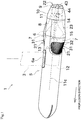
- FIG. 1 is a perspective view illustrating an overall structure of an underwater propulsion unit 1 according to an embodiment of the present invention.
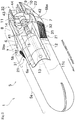
- FIG. 2 is a perspective view illustrating a partial cross section of the underwater propulsion unit 1.
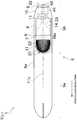
- FIG. 3 is a side view of the underwater propulsion unit 1.
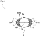
- FIG. 4 is a front view of the underwater propulsion unit 1.
- the underwater propulsion unit 1 illustrated in FIG. 1 causes propulsion in a certain direction with thrust obtained from electricity.
- the underwater propulsion unit 1 is attached onto a lower portion of an unillustrated sliding body (vehicle), which slides over water with a human aboard, and applies propulsion to the sliding body.
- the sliding body may be shaped like, for example, a horizontal plate but is not limited to this shape.
- the underwater propulsion unit 1 includes a housing 5, a propeller 11, and a motor 12.
- the housing 5 forms the exterior of the underwater propulsion unit 1 and accommodates the propeller 11, the motor 12, and the like.
- the housing 5 includes two introduction inlets 21 for introducing water into the housing 5 and one spout outlet 22 for spouting water outside the housing 5.
- the introduction inlets 21 and the spout outlet 22 are connected through a channel 23 formed inside the housing 5. The structure of the housing 5 will be described in detail later.
- the propeller 11 is rotatably supported inside the housing 5.
- the propeller 11 is disposed in an intermediate portion of the channel 23 formed inside the housing 5 so that an axis 11c of the propeller 11 is oriented in a fore-and-aft direction.
- the propeller 11 is rotated by driving force of the motor 12 and delivers the water that has entered the channel 23 through the introduction inlets 21 to the spout outlet 22. Accordingly, the water is spouted rearward from the spout outlet 22 and its reaction force moves the underwater propulsion unit 1 forward.
- the front and rear in a direction in which the underwater propulsion unit 1 moves by spouting water from the spout outlet 22 may simply be expressed with “fore-and-aft,” “front,” “forward,” “rear,” “rearward,” etc.
- the left and right in the propulsion direction of the underwater propulsion unit 1 may simply be expressed with “left,” “right,” “lateral,” etc.
- Up and down directions in a state where the underwater propulsion unit 1 is moving forward may simply be expressed with “up,” “upward,” “upper,” “down,” “downward,” “lower,” etc.
- the motor 12 is configured as an alternating current electric motor for example.
- the motor 12 is disposed inside a waterproof case 6 (waterproof space) of the housing 5.
- An output shaft 13 of the motor 12 extends rearward and is coupled to a propeller shaft 14 rotatably supported by the waterproof case 6 with interposition of a coupling 15.
- a rear end portion of the propeller shaft 14 is disposed to come out of the waterproof case 6 and projects into the channel 23.
- the propeller 11 is fixed to the propeller shaft 14.
- the housing 5 includes the waterproof case 6, filter covers 7, a stream guiding case 8, a propeller supporting case 9, and a rear case 10.
- a large portion of the waterproof case 6 is shaped like a cylinder that is long and narrow in the fore-and-aft direction.
- a rear end portion of the waterproof case 6 (a portion covered by the stream guiding case 8 described later) is approximately shaped like a cone that becomes narrower rearward.
- a front end portion of the waterproof case 6 is approximately shaped like a hemisphere and accordingly, a front end portion of the housing 5 obtains a streamlined shape.
- a fixing part 6a is provided on an upper portion of the waterproof case 6. As indicated with a chain line in FIG. 1 , a strut 3 having a shape that is long and narrow in the up-and-down direction is fixed to the fixing part 6a with an unillustrated fixing member (e.g. a bolt or the like).
- an unillustrated fixing member e.g. a bolt or the like.
- the waterproof case 6 is structured to have a hollow shape and a long narrow space is formed inside the waterproof case 6 in the fore-and-aft direction.
- the above-described motor 12 is disposed and, for example, an unillustrated inverter for changing the rotation speed of the motor 12 is further disposed.
- an unillustrated storage battery for supplying power to the motor 12 and the like is disposed. This storage battery may be placed inside the housing 5.
- the propeller shaft 14 is disposed in the fore-and-aft direction and, as illustrated in FIG. 2 , is rotatably supported by bearings 41.
- the axis of the propeller shaft 14 agrees with the axis of the output shaft 13 of the motor 12.
- a sealing member 42 for preventing intrusion of water into the waterproof case 6 is disposed between the waterproof case 6 and the propeller shaft 14.
- the filter covers 7 are fixed as a pair in left and right side rear portions of the waterproof case 6. Thus, a space through which water can pass is formed between each filter cover 7 and the waterproof case 6.
- Each filter cover 7 has a shape that is inclined so that the amount of its projection in the left and right direction gradually increases rearward. In other words, each filter cover 7 is inclined to have a distance that gradually increases from an axis 11c of the propeller 11 rearward.
- Each of the above-described introduction inlets 21 for introducing water into the inside space is opened through a large portion of the inclined surface.
- each introduction inlet 21 is arranged so that the distance from the axis 11c of the propeller 11 increases rearward. Accordingly, as the underwater propulsion unit 1 moves forward, water present further forward than the introduction inlets 21 comes inside the filter covers 7 through the introduction inlets 21 in a direction parallel to the axis 11c of the propeller 11 (see the blank arrow in FIG. 3 ). The pressure of the water introduced from the introduction inlet 21 increases with rise in the speed of the underwater propulsion unit 1. As described above, in the present embodiment, particularly during a high-speed navigation, water in a high pressure state can be smoothly taken into the filter covers 7.
- Each filter cover 7 includes a filter 31 disposed along the opened surface of the introduction inlet 21.
- the filter 31 includes a large number of rod-like members (foreign matter restricting members) 32, which are disposed at spacings.
- the rod-like members 32 can reject ingress of an underwater foreign matter from the introduction inlet 21 into the housing 5.
- the underwater propulsion unit 1 can cause propulsion while smoothly thrusting an underwater foreign matter outward using the filter 31.
- the rod-like members 32 When viewed in the direction in which the filter covers 7 project (in the present embodiment, the left and right direction), as illustrated in FIG. 3 , the rod-like members 32 are disposed approximately radially. Therefore, the orientations in their longitudinal direction vary little by little among the rod-like members 32. However, the orientation of every rod-like member 32 in the longitudinal direction is substantially along the orientation of the axis 11c of the propeller 11. Specifically, when viewed in the above-described direction, the longitudinal direction of each rod-like member 32 is inclined at an angle smaller than 45° relative to the axis 11c of the propeller 11. That is, each rod-like member 32 is inclined at an angle smaller than approximately 45° relative to the axis 11c of the propeller 11.
- the rod-like member 32 may have a portion that is inclined at an angle larger than or equal to 45° relative to the axis 11c of the propeller 11.
- the stream guiding case 8 is, for example, attached to cover the rear portion of the waterproof case 6 as illustrated in FIG. 2 .
- a rear end portion of the stream guiding case 8 has a circular shape.
- Side portions of the stream guiding case 8 on both the left and right sides each have a shape that is inclined so that the amount of its projection in the left and right direction gradually increases forward from the rear end portion.
- the above-described filter cover 7 is fixed in front of corresponding one of the portions that project as a pair.
- the stream guiding case 8 is structured to have a hollow shape and a space through which water can pass is formed inside the stream guiding case 8.
- the inside of the pair of filter covers 7 and the inside of the stream guiding case 8 are connected to each other.
- water delivered from the pair of filter covers 7 to the stream guiding case 8 positioned further rearward flows diagonally to approach the axis 11c of the propeller 11 inside the stream guiding case 8 and merges together.
- the propeller supporting case 9 is attached to be connected to a rear portion of the stream guiding case 8.
- the above-described propeller 11 is disposed inside the propeller supporting case 9.
- the propeller supporting case 9 is structured to have a hollow shape and a space through which water can pass is formed inside the propeller supporting case 9.
- the inside of the stream guiding case 8 and the inside of the propeller supporting case 9 are connected to each other. Accordingly, the water in the stream guiding case 8 can flow to the propeller supporting case 9.
- the above-described spout outlet 22 is provided at a rear end of the propeller supporting case 9. The space inside the propeller supporting case 9 is opened through the spout outlet 22.
- a boss part 43 for supporting a rear end portion of the propeller shaft 14 is disposed in a central portion of the space formed inside the propeller supporting case 9.
- the boss part 43 is fixed to the propeller supporting case 9 using rectifying blades 44, which are radially disposed.
- An unillustrated bearing is disposed inside the boss part 43 and the bearing enables an end portion of the propeller shaft 14 to be rotatably supported.
- the rear case 10 is formed into a cylindrical shape to cover the outside of the propeller supporting case 9 and attached to be connected to the rear portion of the stream guiding case 8.
- the outside diameter of the rear case 10 gradually decreases rearward and accordingly, a rear end portion of the housing 5 (around the spout outlet 22) obtains a streamlined shape.
- the channel 23 inside the housing 5 is formed by mutual connection among the inside of the filter covers 7, the inside of the stream guiding case 8, and the inside of the propeller supporting case 9. While the introduction inlets 21 are disposed at a front end of the channel 23, the spout outlet 22 is disposed at a rear end of the channel 23.
- the housing 5 according to the present embodiment having the above-described structure can be divided in the fore-and-aft direction into a first portion 5a and a second portion 5b with a boundary therebetween being a front end portion of each filter cover 7, as illustrated in FIG. 2 .
- the first portion 5a is constituted of portions except the rear portion of the waterproof case 6.
- the second portion 5b is a portion where the channel 23 of water is formed inside the housing 5, and is disposed further rearward than the first portion 5a.
- the introduction inlets 21 and the spout outlet 22 are disposed in the second portion 5b.
- the portions where the filter cover 7 and the stream guiding case 8 project in the left and right direction can be collectively referred to as a projection 5bx.
- the projections 5bx are disposed in the second portion 5b.
- the projection 5bx of the second portion 5b is a portion that projects further outward in the left and right direction than the first portion 5a.
- Each introduction inlet 21 is disposed in a front portion of the projection 5bx as illustrated in FIGs. 2 and 3 .
- the distance between each introduction inlet 21 and the axis 11c of the propeller 11 is longer than the distance between an external wall surface of the first portion 5a and the axis 11c of the propeller 11.
- each introduction inlet 21 is provided further outward than the first portion 5a while being oriented in a direction except a downward direction.
- the underwater propulsion unit 1 includes the propeller 11, the motor 12, and the housing 5.
- the motor 12 is disposed further forward in the propulsion direction than the propeller 11 and drives the propeller 11 into rotation.
- the housing 5 accommodates the motor 12 and the propeller 11.
- the housing 5 includes the first portion 5a and the second portion 5b.
- the second portion 5b is disposed further rearward in the propulsion direction than the first portion 5a.
- the introduction inlets 21 and the spout outlet 22 are provided in the second portion 5b.
- the introduction inlets 21 introduce water into the housing 5.
- the spout outlet 22 allows water introduced from the introduction inlet 21 and delivered by the propeller 11 to be spouted outside the housing 5.
- each introduction inlet 21 When viewed in a direction parallel to the propulsion direction, each introduction inlet 21 is disposed further outward than the first portion 5a as illustrated in FIG. 4 .
- the introduction inlets 21 introduce water into the housing 5 in a direction parallel to the axis 11c of the propeller 11.
- water present near the external wall of the first portion 5a can be introduced smoothly from the introduction inlets 21 into the housing 5 with the propulsion of the underwater propulsion unit 1. Further, when the underwater propulsion unit 1 causes propulsion at a higher speed, water in a higher pressure state can be introduced from the introduction inlets 21. Accordingly, particularly during a high-speed navigation, occurrence of cavitation near the propeller 11 can be prevented. As a result, the propulsion efficiency can be enhanced.
- the second portion 5b includes the projections 5bx that each project further outward than the first portion 5a as illustrated in FIG. 4 .
- Each introduction inlet 21 is disposed in the front portion of the projection 5bx in the propulsion direction.
- each projection 5bx projects in a direction different from a downward direction as illustrated in FIG. 4 .
- the introduction inlets 21 are not disposed in a bottom portion of the underwater propulsion unit 1. Accordingly, even when the underwater propulsion unit 1 runs on a sandy seashore for example, entrance of a large amount of sands from the introduction inlets 21 into the housing 5 can be prevented. As a result, burden of maintenance, such as cleaning and the like, can be reduced.
- the filters 31 for restricting entrance of a foreign matter into the introduction inlets 21 are each disposed along a surface (an opened surface of the introduction inlet 21) from which the distance to the axis 11c of the propeller 11 increases rearward in the propulsion direction.
- the filters 31 can prevent an underwater foreign matter from intruding from the introduction inlets 21 into the housing 5. Moreover, since each filter 31 is disposed along the surface inclined as described above, the underwater propulsion unit 1 can cause propulsion while smoothly thrusting a foreign matter outward using the filters 31.
- each filter 31 includes the rod-like members 32 formed to be long and narrow.
- each projection 5bx projects further in the left and right direction than the first portion 5a.
- each rod-like member 32 in its longitudinal direction includes a portion inclined at an angle smaller than 45° relative to the axis 11c of the propeller 11.
- the waterproof case 6 (the first portion 5a of the housing 5) may be structured to have any shape, such as an elliptic cylindrical shape, a polygonal cylindrical shape, or the like, instead of the cylindrical shape.
- the directions in which the projections 5bx project from the first portion 5a may be, for example, diagonally upper left and right directions instead of the left and right directions.
- the number of the projections 5bx (in other words, the number of the introduction inlets 21) is not limited to two, which form a pair on the left and right sides.
- the structure may be changed to have, for example, only one projection that projects upward or downward or to have three projections that project downward, upward to the left, and upward to the right.
- each introduction inlet 21 (in other words, the filter surface of each filter 31) may be changed to be perpendicular to the axis 11c of the propeller 11 instead of being inclined as in FIG. 1 .
- At least the filter covers 7 or the stream guiding case 8 may be integrally formed with the waterproof case 6.
- the filter covers 7 and the stream guiding case 8 may be integrally formed with each other.
- the stream guiding case 8, the propeller supporting case 9, and the like may be integrally formed with each other.
- the filter covers 7 may be omitted in the underwater propulsion unit 1.
- only portions of the stream guiding case 8 projecting in the left and right directions constitute the projections 5bx.
- An opening at a front end of a portion of the stream guiding case 8 projecting in the left or right direction forms each introduction inlet 21.
- the waterproof case 6 may be members separable at the boundary between the first portion 5a and the second portion 5b.
- each rod-like member 32 When viewed in the direction in which the projections 5bx project from the first portion 5a (in the left and right direction), each rod-like member 32 may be disposed in parallel to the propeller 11.
- a speed reducer for reducing the rotation speed may be provided between the output shaft 13 of the motor 12 and the propeller shaft 14.
- the underwater propulsion unit 1 is not limited to the structure attached to a sliding body with interposition of the fixing part 6a when used.
- the underwater propulsion unit 1 can be used as a diver propulsion unit with a handle attached to a front portion or the like of the housing 5 and held by a diver who goes under water to operate the unit.
Landscapes
- Engineering & Computer Science (AREA)
- Mechanical Engineering (AREA)
- Chemical & Material Sciences (AREA)
- Combustion & Propulsion (AREA)
- Ocean & Marine Engineering (AREA)
- Aviation & Aerospace Engineering (AREA)
- Toys (AREA)
Abstract
Description
- The present invention relates to an underwater propulsion unit that causes propulsion in water by rotating a propeller using a motor.
- This type of underwater propulsion unit is disclosed in, for example, Patent Literature 1 (hereinafter, PTL 1) and Patent Literature 2 (hereinafter, PTL 2). In each of the hydrofoil watercrafts of
PTL 1 and PTL 2, an electric motor and a propulsion system are integrated in a pod designed to be embedded in a hydrofoil. The propulsion system includes a propeller and a duct. -
- PTL 1: Specification of
U.S. Patent No. 9359044 - PTL 2: Specification of
U.S. Patent Application Publication No. 2016/0185430 - The underwater propulsion units used in the hydrofoil watercrafts of
PTL 1 and PTL 2 each have a structure in which a propeller is disposed inside a cylindrical duct formed with a relatively large diameter. Water is introduced from a large opening (an introduction inlet) formed at the front of the duct and the water is delivered rearward to spout from a spout outlet on the back side. Thus, to achieve downsizing of the rear part of the unit is difficult and entrance of a relatively large foreign matter with water into the duct can be caused. - It is therefore conceivable that, with a structure where an introduction inlet for introducing water is opened through, for example, a side surface of the unit to take in water in a lateral or diagonal direction, a simple shape with less resistance against water can be achieved and entrance of a large foreign matter can be prevented. In this structure, however, particularly during a high-speed navigation, to introduce a sufficient amount of water from the introduction inlet into the unit is difficult. Therefore, the pressure of the water supplied to the propeller can decrease and cavitation can easily occur around the propeller and accordingly, the propulsion efficiency can be reduced. In this point, the structure is susceptible to improvement.
- The present invention has been made in view of such circumstances and is aimed at achieving high propulsion efficiency of an underwater propulsion unit particularly during a high-speed navigation by introducing a sufficient amount of water from an introduction inlet.
- The problems that the present invention attempts to solve are described above and next, solutions for solving these problems and advantages thereof are described below.
- In an aspect of the present invention, an underwater propulsion unit having the following structure is provided. That is, this underwater propulsion unit includes a propeller, a motor, and a housing. The motor is disposed further forward in a propulsion direction than the propeller and drives the propeller into rotation. The housing accommodates the motor and the propeller. The housing includes a first portion and a second portion. The second portion is disposed further rearward in the propulsion direction than the first portion. An introduction inlet and a spout outlet are provided in the second portion. The introduction inlet introduces water into the housing. The spout outlet allows water introduced from the introduction inlet and delivered by the propeller to be spouted outside the housing. When viewed in a direction parallel to the propulsion direction, the introduction inlet is disposed further outward than the first portion. The introduction inlet introduces water into the housing in a direction parallel to an axis of the propeller.
- Thus, water present near an external wall of the first portion can be introduced smoothly from the introduction inlet into the housing with the propulsion of the underwater propulsion unit. Further, when the underwater propulsion unit causes propulsion at a higher speed, water in a higher pressure state can be introduced from the introduction inlet. Accordingly, particularly during a high-speed navigation, occurrence of cavitation near the propeller can be prevented.
As a result, the propulsion efficiency can be enhanced. - The above-described underwater propulsion unit may preferably be structured as follows. That is, when viewed in a direction parallel to the propulsion direction, the second portion includes a projection that projects further outward than the first portion. The introduction inlet is disposed in a front portion of the projection in the propulsion direction.
- Thus, when the underwater propulsion unit causes propulsion, water present further forward than the projection can be introduced smoothly into the housing through the introduction inlet.
- It is preferable that, when the underwater propulsion unit is viewed in a direction parallel to the propulsion direction, the projection project in a direction different from a downward direction.
- Thus, the introduction inlet is not disposed in a bottom portion of the underwater propulsion unit. Accordingly, even when the underwater propulsion unit runs on a sandy seashore for example, entrance of a large amount of sands from the introduction inlet into the housing can be prevented. As a result, burden of maintenance, such as cleaning and the like, can be reduced.
- In the underwater propulsion unit, it is preferable that a filter that restricts entrance of a foreign matter through the introduction inlet be disposed along a surface from which a distance to an axis of the propeller increases rearward in the propulsion direction.
- Thus, the filter can prevent an underwater foreign matter from intruding into the housing from the introduction inlet. In addition, since the filter is disposed along the surface thus inclined, the underwater propulsion unit can cause propulsion while smoothly thrusting a foreign matter outward using the filter.
- The above-described underwater propulsion unit may preferably be structured as follows. That is, the filter includes a foreign matter restricting member formed to be long and narrow. When viewed in parallel to a direction in which the projection projects further than the first portion when viewed in the propulsion direction, the foreign matter restricting member in a longitudinal direction includes at least one of a portion parallel to the axis of the propeller and a portion inclined at an angle smaller than 45° relative to the axis of the propeller.
- Thus, it is enabled to prevent a foreign matter from getting caught and held by the foreign matter restricting member of the filter. Accordingly, increase in resistance during propulsion can be prevented.
-
- [
FIG. 1 ] A perspective view illustrating an overall structure of an underwater propulsion unit according to an embodiment of the present invention. - [
FIG. 2 ] A perspective view illustrating a partial cross section of the underwater propulsion unit. - [
FIG. 3 ] A side view of the underwater propulsion unit. - [
FIG. 4 ] A front view of the underwater propulsion unit. - Embodiments of the present invention are described below with reference to the drawings.
FIG. 1 is a perspective view illustrating an overall structure of anunderwater propulsion unit 1 according to an embodiment of the present invention.FIG. 2 is a perspective view illustrating a partial cross section of theunderwater propulsion unit 1.FIG. 3 is a side view of theunderwater propulsion unit 1.FIG. 4 is a front view of theunderwater propulsion unit 1. - The
underwater propulsion unit 1 illustrated inFIG. 1 causes propulsion in a certain direction with thrust obtained from electricity. In the present embodiment, theunderwater propulsion unit 1 is attached onto a lower portion of an unillustrated sliding body (vehicle), which slides over water with a human aboard, and applies propulsion to the sliding body. The sliding body may be shaped like, for example, a horizontal plate but is not limited to this shape. - The
underwater propulsion unit 1 includes ahousing 5, apropeller 11, and amotor 12. - The
housing 5 forms the exterior of theunderwater propulsion unit 1 and accommodates thepropeller 11, themotor 12, and the like. Thehousing 5 includes twointroduction inlets 21 for introducing water into thehousing 5 and onespout outlet 22 for spouting water outside thehousing 5. The introduction inlets 21 and thespout outlet 22 are connected through achannel 23 formed inside thehousing 5. The structure of thehousing 5 will be described in detail later. - The
propeller 11 is rotatably supported inside thehousing 5. Thepropeller 11 is disposed in an intermediate portion of thechannel 23 formed inside thehousing 5 so that anaxis 11c of thepropeller 11 is oriented in a fore-and-aft direction. Thepropeller 11 is rotated by driving force of themotor 12 and delivers the water that has entered thechannel 23 through theintroduction inlets 21 to thespout outlet 22. Accordingly, the water is spouted rearward from thespout outlet 22 and its reaction force moves theunderwater propulsion unit 1 forward. - In the description below, the front and rear in a direction in which the
underwater propulsion unit 1 moves by spouting water from the spout outlet 22 (a propulsion direction) may simply be expressed with "fore-and-aft," "front," "forward," "rear," "rearward," etc. Further, the left and right in the propulsion direction of theunderwater propulsion unit 1 may simply be expressed with "left," "right," "lateral," etc. Up and down directions in a state where theunderwater propulsion unit 1 is moving forward may simply be expressed with "up," "upward," "upper," "down," "downward," "lower," etc. - The
motor 12 is configured as an alternating current electric motor for example. Themotor 12 is disposed inside a waterproof case 6 (waterproof space) of thehousing 5. Anoutput shaft 13 of themotor 12 extends rearward and is coupled to apropeller shaft 14 rotatably supported by thewaterproof case 6 with interposition of acoupling 15. A rear end portion of thepropeller shaft 14 is disposed to come out of thewaterproof case 6 and projects into thechannel 23. Thepropeller 11 is fixed to thepropeller shaft 14. - The
housing 5 is described below in detail. Thehousing 5 includes thewaterproof case 6, filter covers 7, astream guiding case 8, apropeller supporting case 9, and arear case 10. - A large portion of the
waterproof case 6 is shaped like a cylinder that is long and narrow in the fore-and-aft direction. A rear end portion of the waterproof case 6 (a portion covered by thestream guiding case 8 described later) is approximately shaped like a cone that becomes narrower rearward. A front end portion of thewaterproof case 6 is approximately shaped like a hemisphere and accordingly, a front end portion of thehousing 5 obtains a streamlined shape. - A fixing
part 6a is provided on an upper portion of thewaterproof case 6. As indicated with a chain line inFIG. 1 , astrut 3 having a shape that is long and narrow in the up-and-down direction is fixed to the fixingpart 6a with an unillustrated fixing member (e.g. a bolt or the like). Thus, the sliding body and theunderwater propulsion unit 1 can be coupled to each other. - As illustrated in
FIG. 2 , thewaterproof case 6 is structured to have a hollow shape and a long narrow space is formed inside thewaterproof case 6 in the fore-and-aft direction. In this space, the above-describedmotor 12 is disposed and, for example, an unillustrated inverter for changing the rotation speed of themotor 12 is further disposed. Outside thehousing 5, an unillustrated storage battery for supplying power to themotor 12 and the like is disposed. This storage battery may be placed inside thehousing 5. - In a rear portion of the
waterproof case 6, thepropeller shaft 14 is disposed in the fore-and-aft direction and, as illustrated inFIG. 2 , is rotatably supported bybearings 41. The axis of thepropeller shaft 14 agrees with the axis of theoutput shaft 13 of themotor 12. Further, a sealingmember 42 for preventing intrusion of water into thewaterproof case 6 is disposed between thewaterproof case 6 and thepropeller shaft 14. - The filter covers 7 are fixed as a pair in left and right side rear portions of the
waterproof case 6. Thus, a space through which water can pass is formed between eachfilter cover 7 and thewaterproof case 6. Eachfilter cover 7 has a shape that is inclined so that the amount of its projection in the left and right direction gradually increases rearward. In other words, eachfilter cover 7 is inclined to have a distance that gradually increases from anaxis 11c of thepropeller 11 rearward. Each of the above-describedintroduction inlets 21 for introducing water into the inside space is opened through a large portion of the inclined surface. - Thus, the opened surface of each
introduction inlet 21 is arranged so that the distance from theaxis 11c of thepropeller 11 increases rearward. Accordingly, as theunderwater propulsion unit 1 moves forward, water present further forward than the introduction inlets 21 comes inside the filter covers 7 through theintroduction inlets 21 in a direction parallel to theaxis 11c of the propeller 11 (see the blank arrow inFIG. 3 ). The pressure of the water introduced from theintroduction inlet 21 increases with rise in the speed of theunderwater propulsion unit 1. As described above, in the present embodiment, particularly during a high-speed navigation, water in a high pressure state can be smoothly taken into the filter covers 7. - Each
filter cover 7 includes afilter 31 disposed along the opened surface of theintroduction inlet 21. Thefilter 31 includes a large number of rod-like members (foreign matter restricting members) 32, which are disposed at spacings. The rod-like members 32 can reject ingress of an underwater foreign matter from theintroduction inlet 21 into thehousing 5. In addition, since eachfilter 31 is disposed along the opened surface inclined as described above, theunderwater propulsion unit 1 can cause propulsion while smoothly thrusting an underwater foreign matter outward using thefilter 31. - When viewed in the direction in which the filter covers 7 project (in the present embodiment, the left and right direction), as illustrated in
FIG. 3 , the rod-like members 32 are disposed approximately radially. Therefore, the orientations in their longitudinal direction vary little by little among the rod-like members 32. However, the orientation of every rod-like member 32 in the longitudinal direction is substantially along the orientation of theaxis 11c of thepropeller 11. Specifically, when viewed in the above-described direction, the longitudinal direction of each rod-like member 32 is inclined at an angle smaller than 45° relative to theaxis 11c of thepropeller 11. That is, each rod-like member 32 is inclined at an angle smaller than approximately 45° relative to theaxis 11c of thepropeller 11. Accordingly, when theunderwater propulsion unit 1 is moving forward, a foreign matter that hits the rod-like members 32 can be allowed to escape smoothly rearward without getting caught by the rod-like members 32. The rod-like member 32 may have a portion that is inclined at an angle larger than or equal to 45° relative to theaxis 11c of thepropeller 11. - The
stream guiding case 8 is, for example, attached to cover the rear portion of thewaterproof case 6 as illustrated inFIG. 2 . A rear end portion of thestream guiding case 8 has a circular shape. Side portions of thestream guiding case 8 on both the left and right sides each have a shape that is inclined so that the amount of its projection in the left and right direction gradually increases forward from the rear end portion. The above-describedfilter cover 7 is fixed in front of corresponding one of the portions that project as a pair. - The
stream guiding case 8 is structured to have a hollow shape and a space through which water can pass is formed inside thestream guiding case 8. The inside of the pair of filter covers 7 and the inside of thestream guiding case 8 are connected to each other. In this structure, water delivered from the pair of filter covers 7 to thestream guiding case 8 positioned further rearward flows diagonally to approach theaxis 11c of thepropeller 11 inside thestream guiding case 8 and merges together. - The
propeller supporting case 9 is attached to be connected to a rear portion of thestream guiding case 8. The above-describedpropeller 11 is disposed inside thepropeller supporting case 9. - The
propeller supporting case 9 is structured to have a hollow shape and a space through which water can pass is formed inside thepropeller supporting case 9. The inside of thestream guiding case 8 and the inside of thepropeller supporting case 9 are connected to each other. Accordingly, the water in thestream guiding case 8 can flow to thepropeller supporting case 9. The above-describedspout outlet 22 is provided at a rear end of thepropeller supporting case 9. The space inside thepropeller supporting case 9 is opened through thespout outlet 22. - A
boss part 43 for supporting a rear end portion of thepropeller shaft 14 is disposed in a central portion of the space formed inside thepropeller supporting case 9. Theboss part 43 is fixed to thepropeller supporting case 9 usingrectifying blades 44, which are radially disposed. An unillustrated bearing is disposed inside theboss part 43 and the bearing enables an end portion of thepropeller shaft 14 to be rotatably supported. - The
rear case 10 is formed into a cylindrical shape to cover the outside of thepropeller supporting case 9 and attached to be connected to the rear portion of thestream guiding case 8. The outside diameter of therear case 10 gradually decreases rearward and accordingly, a rear end portion of the housing 5 (around the spout outlet 22) obtains a streamlined shape. - In this structure, the
channel 23 inside thehousing 5 is formed by mutual connection among the inside of the filter covers 7, the inside of thestream guiding case 8, and the inside of thepropeller supporting case 9. While theintroduction inlets 21 are disposed at a front end of thechannel 23, thespout outlet 22 is disposed at a rear end of thechannel 23. - For consideration, the
housing 5 according to the present embodiment having the above-described structure can be divided in the fore-and-aft direction into afirst portion 5a and asecond portion 5b with a boundary therebetween being a front end portion of eachfilter cover 7, as illustrated inFIG. 2 . Thefirst portion 5a is constituted of portions except the rear portion of thewaterproof case 6. Thesecond portion 5b is a portion where thechannel 23 of water is formed inside thehousing 5, and is disposed further rearward than thefirst portion 5a. The introduction inlets 21 and thespout outlet 22 are disposed in thesecond portion 5b. - The portions where the
filter cover 7 and thestream guiding case 8 project in the left and right direction can be collectively referred to as a projection 5bx. The projections 5bx are disposed in thesecond portion 5b. - Assuming that the
housing 5 is divided in the fore-and-aft direction as described above for consideration, it can be said that, when viewed in a direction parallel to the propulsion direction as inFIG. 4 , the projection 5bx of thesecond portion 5b is a portion that projects further outward in the left and right direction than thefirst portion 5a. Eachintroduction inlet 21 is disposed in a front portion of the projection 5bx as illustrated inFIGs. 2 and3 . - In other words, as illustrated in
FIG. 4 , the distance between eachintroduction inlet 21 and theaxis 11c of thepropeller 11 is longer than the distance between an external wall surface of thefirst portion 5a and theaxis 11c of thepropeller 11. Thus, as described above, water present near the external wall on the both left and right sides of thefirst portion 5a can be taken smoothly from theintroduction inlets 21 into thehousing 5 with the propulsion of theunderwater propulsion unit 1. Accordingly, decrease in the pressure of water in a portion in thechannel 23 positioned on the upstream side of thepropeller 11 can be suppressed. As a result, occurrence of cavitation near thepropeller 11 rotating can be prevented. - When the
underwater propulsion unit 1 is viewed in a direction parallel to the propulsion direction (in the present embodiment, from the front) as illustrated inFIG. 4 , the projection 5bx is provided to project horizontally further in the left and right direction than thefirst portion 5a instead of projecting further downward. In other words, eachintroduction inlet 21 is provided further outward than thefirst portion 5a while being oriented in a direction except a downward direction. Thus, if theunderwater propulsion unit 1 is used at, for example, a sandy beach and runs on the sandy seashore, entrance of sands from theintroduction inlet 21 can be hindered because of the structure. - As described above, the
underwater propulsion unit 1 according to the present embodiment includes thepropeller 11, themotor 12, and thehousing 5. Themotor 12 is disposed further forward in the propulsion direction than thepropeller 11 and drives thepropeller 11 into rotation. Thehousing 5 accommodates themotor 12 and thepropeller 11. Thehousing 5 includes thefirst portion 5a and thesecond portion 5b. Thesecond portion 5b is disposed further rearward in the propulsion direction than thefirst portion 5a. The introduction inlets 21 and thespout outlet 22 are provided in thesecond portion 5b. The introduction inlets 21 introduce water into thehousing 5. Thespout outlet 22 allows water introduced from theintroduction inlet 21 and delivered by thepropeller 11 to be spouted outside thehousing 5. When viewed in a direction parallel to the propulsion direction, eachintroduction inlet 21 is disposed further outward than thefirst portion 5a as illustrated inFIG. 4 . The introduction inlets 21 introduce water into thehousing 5 in a direction parallel to theaxis 11c of thepropeller 11. - Thus, water present near the external wall of the
first portion 5a can be introduced smoothly from theintroduction inlets 21 into thehousing 5 with the propulsion of theunderwater propulsion unit 1. Further, when theunderwater propulsion unit 1 causes propulsion at a higher speed, water in a higher pressure state can be introduced from theintroduction inlets 21. Accordingly, particularly during a high-speed navigation, occurrence of cavitation near thepropeller 11 can be prevented. As a result, the propulsion efficiency can be enhanced. - When the
underwater propulsion unit 1 according to the present embodiment is viewed in a direction parallel to the propulsion direction, thesecond portion 5b includes the projections 5bx that each project further outward than thefirst portion 5a as illustrated inFIG. 4 . Eachintroduction inlet 21 is disposed in the front portion of the projection 5bx in the propulsion direction. - Thus, when the
underwater propulsion unit 1 causes propulsion, water present further forward than the projection 5bx can be introduced smoothly into thehousing 5 through theintroduction inlets 21. - When the
underwater propulsion unit 1 according to the present embodiment is viewed in a direction parallel to the propulsion direction, each projection 5bx projects in a direction different from a downward direction as illustrated inFIG. 4 . - Thus, the
introduction inlets 21 are not disposed in a bottom portion of theunderwater propulsion unit 1. Accordingly, even when theunderwater propulsion unit 1 runs on a sandy seashore for example, entrance of a large amount of sands from theintroduction inlets 21 into thehousing 5 can be prevented. As a result, burden of maintenance, such as cleaning and the like, can be reduced. - In addition, in the
underwater propulsion unit 1 according to the present embodiment, thefilters 31 for restricting entrance of a foreign matter into theintroduction inlets 21 are each disposed along a surface (an opened surface of the introduction inlet 21) from which the distance to theaxis 11c of thepropeller 11 increases rearward in the propulsion direction. - Thus, the
filters 31 can prevent an underwater foreign matter from intruding from theintroduction inlets 21 into thehousing 5. Moreover, since eachfilter 31 is disposed along the surface inclined as described above, theunderwater propulsion unit 1 can cause propulsion while smoothly thrusting a foreign matter outward using thefilters 31. - Further, in the
underwater propulsion unit 1 according to the present embodiment, eachfilter 31 includes the rod-like members 32 formed to be long and narrow. In the present embodiment, when viewed in the propulsion direction, each projection 5bx projects further in the left and right direction than thefirst portion 5a. When theunderwater propulsion unit 1 is viewed in parallel to the direction (that is, in the left and right direction), as illustrated inFIG. 3 , each rod-like member 32 in its longitudinal direction includes a portion inclined at an angle smaller than 45° relative to theaxis 11c of thepropeller 11. - Thus, it is enabled to prevent a foreign matter from getting caught and held by the rod-
like members 32 of thefilters 31. Accordingly, increase in resistance during propulsion can be prevented. - While a preferred embodiment of the present invention is described above, the above-described structure may be modified, for example, as follows.
- The waterproof case 6 (the
first portion 5a of the housing 5) may be structured to have any shape, such as an elliptic cylindrical shape, a polygonal cylindrical shape, or the like, instead of the cylindrical shape. - When the
underwater propulsion unit 1 is viewed in a direction parallel to the propulsion direction, the directions in which the projections 5bx project from thefirst portion 5a may be, for example, diagonally upper left and right directions instead of the left and right directions. The number of the projections 5bx (in other words, the number of the introduction inlets 21) is not limited to two, which form a pair on the left and right sides. The structure may be changed to have, for example, only one projection that projects upward or downward or to have three projections that project downward, upward to the left, and upward to the right. - The opened surface of each introduction inlet 21 (in other words, the filter surface of each filter 31) may be changed to be perpendicular to the
axis 11c of thepropeller 11 instead of being inclined as inFIG. 1 . - At least the filter covers 7 or the
stream guiding case 8 may be integrally formed with thewaterproof case 6. The filter covers 7 and thestream guiding case 8 may be integrally formed with each other. Thestream guiding case 8, thepropeller supporting case 9, and the like may be integrally formed with each other. - The filter covers 7 may be omitted in the
underwater propulsion unit 1. In this case, only portions of thestream guiding case 8 projecting in the left and right directions constitute the projections 5bx. An opening at a front end of a portion of thestream guiding case 8 projecting in the left or right direction forms eachintroduction inlet 21. - The
waterproof case 6 may be members separable at the boundary between thefirst portion 5a and thesecond portion 5b. - When viewed in the direction in which the projections 5bx project from the
first portion 5a (in the left and right direction), each rod-like member 32 may be disposed in parallel to thepropeller 11. - A speed reducer for reducing the rotation speed may be provided between the
output shaft 13 of themotor 12 and thepropeller shaft 14. - The
underwater propulsion unit 1 is not limited to the structure attached to a sliding body with interposition of the fixingpart 6a when used. For example, theunderwater propulsion unit 1 can be used as a diver propulsion unit with a handle attached to a front portion or the like of thehousing 5 and held by a diver who goes under water to operate the unit. -
- 1
- underwater propulsion unit
- 5
- housing
- 5a
- first portion
- 5b
- second portion
- 5bx
- projection
- 11
- propeller
- 11c
- axis of propeller
- 12
- motor
- 21
- introduction inlet
- 22
- spout outlet
- 31
- filter
- 32
- rod-like member (foreign matter restricting member)
Claims (5)
- An underwater propulsion unit comprising:a propeller;a motor that is disposed further forward in a propulsion direction than the propeller and drives the propeller into rotation; anda housing that accommodates the motor and the propeller, the housing includinga first portion, anda second portion that is disposed further rearward in the propulsion direction than the first portion, whereinan introduction inlet and a spout outlet are provided in the second portion, the introduction inlet introducing water into the housing, the spout outlet allowing water introduced from the introduction inlet and delivered by the propeller to be spouted outside the housing,when viewed in a direction parallel to the propulsion direction, the introduction inlet is disposed further outward than the first portion, andthe introduction inlet introduces water into the housing in a direction parallel to an axis of the propeller.
- The underwater propulsion unit according to claim 1, wherein
the second portion includes a projection that projects further outward than the first portion when viewed in a direction parallel to the propulsion direction, and
the introduction inlet is disposed in a front portion of the projection in the propulsion direction. - The underwater propulsion unit according to claim 2, wherein
the projection projects in a direction different from a downward direction when viewed in a direction parallel to the propulsion direction. - The underwater propulsion unit according to claim 2 or 3, wherein
a filter that restricts entrance of a foreign matter into the introduction inlet is disposed along a surface from which a distance to the axis of the propeller increases rearward in the propulsion direction. - The underwater propulsion unit according to claim 4, wherein
the filter includes a foreign matter restricting member formed to be long and narrow, and
when viewed in parallel to a direction in which the projection projects further than the first portion when viewed in the propulsion direction, the foreign matter restricting member in a longitudinal direction includes at least one of a portion parallel to the axis of the propeller and a portion inclined at an angle smaller than 45° relative to the axis of the propeller.
Applications Claiming Priority (2)
| Application Number | Priority Date | Filing Date | Title |
|---|---|---|---|
| JP2017051323A JP2018154177A (en) | 2017-03-16 | 2017-03-16 | Underwater propulsion device |
| PCT/JP2018/009094 WO2018168664A1 (en) | 2017-03-16 | 2018-03-08 | Underwater propulsion device |
Publications (2)
| Publication Number | Publication Date |
|---|---|
| EP3578453A1 true EP3578453A1 (en) | 2019-12-11 |
| EP3578453A4 EP3578453A4 (en) | 2020-12-16 |
Family
ID=63523920
Family Applications (1)
| Application Number | Title | Priority Date | Filing Date |
|---|---|---|---|
| EP18766727.4A Pending EP3578453A4 (en) | 2017-03-16 | 2018-03-08 | UNDERWATER DRIVE DEVICE |
Country Status (4)
| Country | Link |
|---|---|
| US (1) | US10960963B2 (en) |
| EP (1) | EP3578453A4 (en) |
| JP (1) | JP2018154177A (en) |
| WO (1) | WO2018168664A1 (en) |
Cited By (1)
| Publication number | Priority date | Publication date | Assignee | Title |
|---|---|---|---|---|
| WO2022037809A1 (en) * | 2020-08-20 | 2022-02-24 | Aerofoils Gmbh | Hydrofoil watercraft |
Families Citing this family (11)
| Publication number | Priority date | Publication date | Assignee | Title |
|---|---|---|---|---|
| CN111086611A (en) * | 2018-10-23 | 2020-05-01 | 东辉休闲运动用品(上海)有限公司 | Underwater propeller |
| CN109333552A (en) * | 2018-11-12 | 2019-02-15 | 张子悦 | An underwater cleaning robot with a bat-wing-shaped silicone body wing membrane |
| CN109552579A (en) * | 2019-01-21 | 2019-04-02 | 中国计量大学 | One kind is small-sized cable remote control type underwater robot |
| DE102019129571A1 (en) | 2019-11-01 | 2021-05-06 | Rosen Swiss Ag | Water sports equipment, in particular foil boards |
| JP2022079901A (en) * | 2020-11-17 | 2022-05-27 | 伊藤忠テクノソリューションズ株式会社 | Varifocal glasses, control method and control program of varifocal glasses |
| US11685491B2 (en) * | 2020-12-01 | 2023-06-27 | City University Of Hong Kong | Hetero-stiffness robotic device |
| CN112833277A (en) * | 2021-02-25 | 2021-05-25 | 中国电建集团西北勘测设计研究院有限公司 | A box-type double-pipe census ship used for the census of underground drainage pipes and culverts |
| EP4426606A4 (en) | 2021-11-03 | 2025-03-19 | Fliteboard Pty Ltd | JET SYSTEMS FOR WATER SPORTS EQUIPMENT |
| CN114313161A (en) * | 2021-12-10 | 2022-04-12 | 深圳市苇渡智能科技有限公司 | Flow guide device and diving equipment |
| CN114872871A (en) * | 2022-04-30 | 2022-08-09 | 杭州舟海智能科技有限责任公司 | Propeller frame structure and propeller |
| CN116902190A (en) * | 2023-09-05 | 2023-10-20 | 江苏大学 | Built-in pump spouts formula underwater vehicle |
Family Cites Families (14)
| Publication number | Priority date | Publication date | Assignee | Title |
|---|---|---|---|---|
| JPH01101294A (en) * | 1987-10-12 | 1989-04-19 | Apollo Sports:Kk | Underwater scooter |
| US5253603A (en) * | 1992-07-10 | 1993-10-19 | Hughes Aircraft Company | Underwater vehicle muffler |
| JPH08239090A (en) * | 1995-03-07 | 1996-09-17 | Mitsubishi Heavy Ind Ltd | Submerged vehicle |
| US5704817A (en) * | 1996-04-16 | 1998-01-06 | Vaughn; Wayne P. | Water surface propulsion device |
| US6217399B1 (en) * | 1999-01-25 | 2001-04-17 | Electric Boat Corporation | Propulsion arrangement for axisymmetric fluid-borne vehicles |
| US6725797B2 (en) * | 1999-11-24 | 2004-04-27 | Terry B. Hilleman | Method and apparatus for propelling a surface ship through water |
| KR100495676B1 (en) * | 2002-09-26 | 2005-06-16 | 국방과학연구소 | Pumpjet apparatus with ring rotor and grooved duct |
| TW200716441A (en) * | 2005-10-21 | 2007-05-01 | Joy Ride Technology Co Ltd | A submersible thruster and surfboard equipped with the submersible thruster |
| JP2007276609A (en) * | 2006-04-06 | 2007-10-25 | Osaka Prefecture Univ | Underwater glider |
| EP1977968B1 (en) * | 2007-04-05 | 2010-09-08 | Joy Ride Technology Co., Ltd. | Propeller driven surfing device |
| DE202013000182U1 (en) * | 2012-01-11 | 2013-02-25 | Isko Koch Gmbh | Drive device for watercraft, in particular for an underwater scooter |
| US9174713B2 (en) * | 2012-11-02 | 2015-11-03 | Raytheon Company | Unmanned underwater vehicle |
| US9359044B2 (en) | 2013-10-10 | 2016-06-07 | Jacob Willem Langelaan | Weight-shift controlled personal hydrofoil watercraft |
| CN103963951B (en) * | 2014-05-16 | 2016-04-13 | 中国船舶重工集团公司第七○二研究所 | A kind of propelling unit for space station, miniature deep-sea |
-
2017
- 2017-03-16 JP JP2017051323A patent/JP2018154177A/en active Pending
-
2018
- 2018-03-08 WO PCT/JP2018/009094 patent/WO2018168664A1/en not_active Ceased
- 2018-03-08 US US16/494,548 patent/US10960963B2/en not_active Expired - Fee Related
- 2018-03-08 EP EP18766727.4A patent/EP3578453A4/en active Pending
Cited By (1)
| Publication number | Priority date | Publication date | Assignee | Title |
|---|---|---|---|---|
| WO2022037809A1 (en) * | 2020-08-20 | 2022-02-24 | Aerofoils Gmbh | Hydrofoil watercraft |
Also Published As
| Publication number | Publication date |
|---|---|
| JP2018154177A (en) | 2018-10-04 |
| EP3578453A4 (en) | 2020-12-16 |
| US20200010162A1 (en) | 2020-01-09 |
| WO2018168664A1 (en) | 2018-09-20 |
| US10960963B2 (en) | 2021-03-30 |
Similar Documents
| Publication | Publication Date | Title |
|---|---|---|
| US10960963B2 (en) | Underwater propulsion unit | |
| EP2493754B1 (en) | Powered water sports board | |
| EP1997567B1 (en) | Underwater cleaning robot | |
| CN104276268B (en) | ship's propulsion unit | |
| JP2022067099A (en) | Submersible turbine | |
| EP3133007A1 (en) | Radiator for saddled vehicle | |
| CN111699132B (en) | Power hydrofoil system | |
| JP2005504227A (en) | Power generation device and turbine unit | |
| KR20210062729A (en) | Stern duct, stern attachment, method of designing stern duct, and ship equipped with stern duct | |
| EP3854675B1 (en) | Underwater thruster | |
| JP3638576B2 (en) | Marine side thruster | |
| US10689078B2 (en) | Waterjet propulsion system and watercraft having a waterjet propulsion system | |
| EP1050454A3 (en) | External electric drive propulsion module arrangement for SWATH vessels | |
| KR20100076216A (en) | Partial opening-type door for the bow thruster | |
| JP5360887B2 (en) | Pod propeller | |
| KR101608714B1 (en) | Driving part and impeller onebody type waterjet electric propulsion unit | |
| JP2010221976A (en) | Pod propeller | |
| CN211543846U (en) | Propeller assembly, propulsion device and navigation equipment | |
| US6729257B2 (en) | Personal watercraft | |
| CN106715258A (en) | Pod propulsion system with tractor propeller | |
| CN216861787U (en) | Duct type supercharged outboard engine propeller protective cover | |
| US9127784B2 (en) | Duct arrangement | |
| JP2008149746A (en) | Contra-rotating propeller device for ship | |
| JP2000211582A (en) | Propulsion device for axisymmetric vehicle traveling in fluid | |
| EP2293975A1 (en) | Gear housing for an aquatic vessel, breakaway safety system for an aquatic vessel and aquatic vessel |
Legal Events
| Date | Code | Title | Description |
|---|---|---|---|
| STAA | Information on the status of an ep patent application or granted ep patent |
Free format text: STATUS: THE INTERNATIONAL PUBLICATION HAS BEEN MADE |
|
| PUAI | Public reference made under article 153(3) epc to a published international application that has entered the european phase |
Free format text: ORIGINAL CODE: 0009012 |
|
| STAA | Information on the status of an ep patent application or granted ep patent |
Free format text: STATUS: REQUEST FOR EXAMINATION WAS MADE |
|
| 17P | Request for examination filed |
Effective date: 20190906 |
|
| AK | Designated contracting states |
Kind code of ref document: A1 Designated state(s): AL AT BE BG CH CY CZ DE DK EE ES FI FR GB GR HR HU IE IS IT LI LT LU LV MC MK MT NL NO PL PT RO RS SE SI SK SM TR |
|
| AX | Request for extension of the european patent |
Extension state: BA ME |
|
| DAV | Request for validation of the european patent (deleted) | ||
| DAX | Request for extension of the european patent (deleted) | ||
| RAP1 | Party data changed (applicant data changed or rights of an application transferred) |
Owner name: YANMAR POWER TECHNOLOGY CO., LTD. |
|
| A4 | Supplementary search report drawn up and despatched |
Effective date: 20201117 |
|
| RIC1 | Information provided on ipc code assigned before grant |
Ipc: B63H 5/07 20060101ALI20201111BHEP Ipc: B63H 11/01 20060101ALI20201111BHEP Ipc: B63H 11/08 20060101ALN20201111BHEP Ipc: B63H 11/02 20060101AFI20201111BHEP Ipc: B63G 8/08 20060101ALI20201111BHEP |
|
| STAA | Information on the status of an ep patent application or granted ep patent |
Free format text: STATUS: EXAMINATION IS IN PROGRESS |
|
| 17Q | First examination report despatched |
Effective date: 20230412 |