EP3578414B1 - Cooling and heating cabinet - Google Patents
Cooling and heating cabinet Download PDFInfo
- Publication number
- EP3578414B1 EP3578414B1 EP18747655.1A EP18747655A EP3578414B1 EP 3578414 B1 EP3578414 B1 EP 3578414B1 EP 18747655 A EP18747655 A EP 18747655A EP 3578414 B1 EP3578414 B1 EP 3578414B1
- Authority
- EP
- European Patent Office
- Prior art keywords
- cooling
- heating cabinet
- disposed
- separation panel
- case
- Prior art date
- Legal status (The legal status is an assumption and is not a legal conclusion. Google has not performed a legal analysis and makes no representation as to the accuracy of the status listed.)
- Active
Links
Images





Classifications
-
- F—MECHANICAL ENGINEERING; LIGHTING; HEATING; WEAPONS; BLASTING
- F25—REFRIGERATION OR COOLING; COMBINED HEATING AND REFRIGERATION SYSTEMS; HEAT PUMP SYSTEMS; MANUFACTURE OR STORAGE OF ICE; LIQUEFACTION SOLIDIFICATION OF GASES
- F25D—REFRIGERATORS; COLD ROOMS; ICE-BOXES; COOLING OR FREEZING APPARATUS NOT OTHERWISE PROVIDED FOR
- F25D31/00—Other cooling or freezing apparatus
- F25D31/005—Combined cooling and heating devices
-
- B—PERFORMING OPERATIONS; TRANSPORTING
- B60—VEHICLES IN GENERAL
- B60H—ARRANGEMENTS OF HEATING, COOLING, VENTILATING OR OTHER AIR-TREATING DEVICES SPECIALLY ADAPTED FOR PASSENGER OR GOODS SPACES OF VEHICLES
- B60H1/00—Heating, cooling or ventilating devices
- B60H1/00507—Details, e.g. mounting arrangements, desaeration devices
- B60H1/00592—Add-on devices, e.g. heat/cooling boxes, compartment dividers, upgrade sets
-
- B—PERFORMING OPERATIONS; TRANSPORTING
- B60—VEHICLES IN GENERAL
- B60N—SEATS SPECIALLY ADAPTED FOR VEHICLES; VEHICLE PASSENGER ACCOMMODATION NOT OTHERWISE PROVIDED FOR
- B60N3/00—Arrangements or adaptations of other passenger fittings, not otherwise provided for
- B60N3/10—Arrangements or adaptations of other passenger fittings, not otherwise provided for of receptacles for food or beverages, e.g. refrigerated
- B60N3/104—Arrangements or adaptations of other passenger fittings, not otherwise provided for of receptacles for food or beverages, e.g. refrigerated with refrigerating or warming systems
-
- A—HUMAN NECESSITIES
- A47—FURNITURE; DOMESTIC ARTICLES OR APPLIANCES; COFFEE MILLS; SPICE MILLS; SUCTION CLEANERS IN GENERAL
- A47J—KITCHEN EQUIPMENT; COFFEE MILLS; SPICE MILLS; APPARATUS FOR MAKING BEVERAGES
- A47J39/00—Heat-insulated warming chambers; Cupboards with heating arrangements for warming kitchen utensils
- A47J39/003—Heat-insulated warming chambers; Cupboards with heating arrangements for warming kitchen utensils with forced air circulation
-
- B—PERFORMING OPERATIONS; TRANSPORTING
- B01—PHYSICAL OR CHEMICAL PROCESSES OR APPARATUS IN GENERAL
- B01F—MIXING, e.g. DISSOLVING, EMULSIFYING OR DISPERSING
- B01F33/00—Other mixers; Mixing plants; Combinations of mixers
- B01F33/45—Magnetic mixers; Mixers with magnetically driven stirrers
- B01F33/453—Magnetic mixers; Mixers with magnetically driven stirrers using supported or suspended stirring elements
- B01F33/4534—Magnetic mixers; Mixers with magnetically driven stirrers using supported or suspended stirring elements using a rod for supporting the stirring element, e.g. stirrer sliding on a rod or mounted on a rod sliding in a tube
-
- B—PERFORMING OPERATIONS; TRANSPORTING
- B01—PHYSICAL OR CHEMICAL PROCESSES OR APPARATUS IN GENERAL
- B01F—MIXING, e.g. DISSOLVING, EMULSIFYING OR DISPERSING
- B01F35/00—Accessories for mixers; Auxiliary operations or auxiliary devices; Parts or details of general application
- B01F35/90—Heating or cooling systems
- B01F35/93—Heating or cooling systems arranged inside the receptacle
-
- B—PERFORMING OPERATIONS; TRANSPORTING
- B60—VEHICLES IN GENERAL
- B60H—ARRANGEMENTS OF HEATING, COOLING, VENTILATING OR OTHER AIR-TREATING DEVICES SPECIALLY ADAPTED FOR PASSENGER OR GOODS SPACES OF VEHICLES
- B60H1/00—Heating, cooling or ventilating devices
-
- B—PERFORMING OPERATIONS; TRANSPORTING
- B60—VEHICLES IN GENERAL
- B60N—SEATS SPECIALLY ADAPTED FOR VEHICLES; VEHICLE PASSENGER ACCOMMODATION NOT OTHERWISE PROVIDED FOR
- B60N3/00—Arrangements or adaptations of other passenger fittings, not otherwise provided for
- B60N3/10—Arrangements or adaptations of other passenger fittings, not otherwise provided for of receptacles for food or beverages, e.g. refrigerated
-
- F—MECHANICAL ENGINEERING; LIGHTING; HEATING; WEAPONS; BLASTING
- F25—REFRIGERATION OR COOLING; COMBINED HEATING AND REFRIGERATION SYSTEMS; HEAT PUMP SYSTEMS; MANUFACTURE OR STORAGE OF ICE; LIQUEFACTION SOLIDIFICATION OF GASES
- F25B—REFRIGERATION MACHINES, PLANTS OR SYSTEMS; COMBINED HEATING AND REFRIGERATION SYSTEMS; HEAT PUMP SYSTEMS
- F25B21/00—Machines, plants or systems, using electric or magnetic effects
- F25B21/02—Machines, plants or systems, using electric or magnetic effects using Peltier effect; using Nernst-Ettinghausen effect
-
- F—MECHANICAL ENGINEERING; LIGHTING; HEATING; WEAPONS; BLASTING
- F25—REFRIGERATION OR COOLING; COMBINED HEATING AND REFRIGERATION SYSTEMS; HEAT PUMP SYSTEMS; MANUFACTURE OR STORAGE OF ICE; LIQUEFACTION SOLIDIFICATION OF GASES
- F25D—REFRIGERATORS; COLD ROOMS; ICE-BOXES; COOLING OR FREEZING APPARATUS NOT OTHERWISE PROVIDED FOR
- F25D17/00—Arrangements for circulating cooling fluids; Arrangements for circulating gas, e.g. air, within refrigerated spaces
- F25D17/04—Arrangements for circulating cooling fluids; Arrangements for circulating gas, e.g. air, within refrigerated spaces for circulating air, e.g. by convection
- F25D17/06—Arrangements for circulating cooling fluids; Arrangements for circulating gas, e.g. air, within refrigerated spaces for circulating air, e.g. by convection by forced circulation
-
- F—MECHANICAL ENGINEERING; LIGHTING; HEATING; WEAPONS; BLASTING
- F25—REFRIGERATION OR COOLING; COMBINED HEATING AND REFRIGERATION SYSTEMS; HEAT PUMP SYSTEMS; MANUFACTURE OR STORAGE OF ICE; LIQUEFACTION SOLIDIFICATION OF GASES
- F25D—REFRIGERATORS; COLD ROOMS; ICE-BOXES; COOLING OR FREEZING APPARATUS NOT OTHERWISE PROVIDED FOR
- F25D31/00—Other cooling or freezing apparatus
-
- B—PERFORMING OPERATIONS; TRANSPORTING
- B01—PHYSICAL OR CHEMICAL PROCESSES OR APPARATUS IN GENERAL
- B01F—MIXING, e.g. DISSOLVING, EMULSIFYING OR DISPERSING
- B01F35/00—Accessories for mixers; Auxiliary operations or auxiliary devices; Parts or details of general application
- B01F35/90—Heating or cooling systems
- B01F2035/98—Cooling
-
- B—PERFORMING OPERATIONS; TRANSPORTING
- B01—PHYSICAL OR CHEMICAL PROCESSES OR APPARATUS IN GENERAL
- B01F—MIXING, e.g. DISSOLVING, EMULSIFYING OR DISPERSING
- B01F35/00—Accessories for mixers; Auxiliary operations or auxiliary devices; Parts or details of general application
- B01F35/90—Heating or cooling systems
- B01F2035/99—Heating
-
- F—MECHANICAL ENGINEERING; LIGHTING; HEATING; WEAPONS; BLASTING
- F25—REFRIGERATION OR COOLING; COMBINED HEATING AND REFRIGERATION SYSTEMS; HEAT PUMP SYSTEMS; MANUFACTURE OR STORAGE OF ICE; LIQUEFACTION SOLIDIFICATION OF GASES
- F25B—REFRIGERATION MACHINES, PLANTS OR SYSTEMS; COMBINED HEATING AND REFRIGERATION SYSTEMS; HEAT PUMP SYSTEMS
- F25B21/00—Machines, plants or systems, using electric or magnetic effects
- F25B21/02—Machines, plants or systems, using electric or magnetic effects using Peltier effect; using Nernst-Ettinghausen effect
- F25B21/04—Machines, plants or systems, using electric or magnetic effects using Peltier effect; using Nernst-Ettinghausen effect reversible
-
- F—MECHANICAL ENGINEERING; LIGHTING; HEATING; WEAPONS; BLASTING
- F25—REFRIGERATION OR COOLING; COMBINED HEATING AND REFRIGERATION SYSTEMS; HEAT PUMP SYSTEMS; MANUFACTURE OR STORAGE OF ICE; LIQUEFACTION SOLIDIFICATION OF GASES
- F25B—REFRIGERATION MACHINES, PLANTS OR SYSTEMS; COMBINED HEATING AND REFRIGERATION SYSTEMS; HEAT PUMP SYSTEMS
- F25B2321/00—Details of machines, plants or systems, using electric or magnetic effects
- F25B2321/02—Details of machines, plants or systems, using electric or magnetic effects using Peltier effects; using Nernst-Ettinghausen effects
-
- F—MECHANICAL ENGINEERING; LIGHTING; HEATING; WEAPONS; BLASTING
- F25—REFRIGERATION OR COOLING; COMBINED HEATING AND REFRIGERATION SYSTEMS; HEAT PUMP SYSTEMS; MANUFACTURE OR STORAGE OF ICE; LIQUEFACTION SOLIDIFICATION OF GASES
- F25B—REFRIGERATION MACHINES, PLANTS OR SYSTEMS; COMBINED HEATING AND REFRIGERATION SYSTEMS; HEAT PUMP SYSTEMS
- F25B2321/00—Details of machines, plants or systems, using electric or magnetic effects
- F25B2321/02—Details of machines, plants or systems, using electric or magnetic effects using Peltier effects; using Nernst-Ettinghausen effects
- F25B2321/025—Removal of heat
- F25B2321/0251—Removal of heat by a gas
-
- F—MECHANICAL ENGINEERING; LIGHTING; HEATING; WEAPONS; BLASTING
- F25—REFRIGERATION OR COOLING; COMBINED HEATING AND REFRIGERATION SYSTEMS; HEAT PUMP SYSTEMS; MANUFACTURE OR STORAGE OF ICE; LIQUEFACTION SOLIDIFICATION OF GASES
- F25D—REFRIGERATORS; COLD ROOMS; ICE-BOXES; COOLING OR FREEZING APPARATUS NOT OTHERWISE PROVIDED FOR
- F25D2201/00—Insulation
- F25D2201/10—Insulation with respect to heat
- F25D2201/14—Insulation with respect to heat using subatmospheric pressure
-
- F—MECHANICAL ENGINEERING; LIGHTING; HEATING; WEAPONS; BLASTING
- F25—REFRIGERATION OR COOLING; COMBINED HEATING AND REFRIGERATION SYSTEMS; HEAT PUMP SYSTEMS; MANUFACTURE OR STORAGE OF ICE; LIQUEFACTION SOLIDIFICATION OF GASES
- F25D—REFRIGERATORS; COLD ROOMS; ICE-BOXES; COOLING OR FREEZING APPARATUS NOT OTHERWISE PROVIDED FOR
- F25D2317/00—Details or arrangements for circulating cooling fluids; Details or arrangements for circulating gas, e.g. air, within refrigerated spaces, not provided for in other groups of this subclass
- F25D2317/06—Details or arrangements for circulating cooling fluids; Details or arrangements for circulating gas, e.g. air, within refrigerated spaces, not provided for in other groups of this subclass with forced air circulation
- F25D2317/068—Details or arrangements for circulating cooling fluids; Details or arrangements for circulating gas, e.g. air, within refrigerated spaces, not provided for in other groups of this subclass with forced air circulation characterised by the fans
- F25D2317/0681—Details thereof
Definitions
- the present invention relates to a cooling and heating cabinet having a heat insulation cavity.
- a cooling and heating cabinet is provided with a storage space for storing food therein, so that a temperature of the storage space may be maintained at a low or high temperature according to a user selection.
- a cooling and heating cabinet for a vehicle is installed in the interior of a vehicle to temporarily keep drinks and small amounts of food.
- thermoelectric element is an electronically cooled substrate utilizing the Peltier effect.
- the Peltier effect refers to a phenomenon in which an electrical current passing through a junction between two types of metal absorbs heat at one terminal and generates heat at the other terminal depending on a direction of the current.
- thermoelectric element heat inside the cooling and heating cabinet for a vehicle is absorbed by a heat absorption terminal, and thus, a temperature inside the cooling and heating cabinet may be maintained at a constant temperature or lower.
- heat emitted from a heat generation terminal may be transferred to the inside of the cooling and heating cabinet for the vehicle, so that the temperature inside the cooling and heating cabinet may be maintained at a predetermined temperature or higher.
- a cooling part such as a heat dissipation plate or a cooling fan may be provided in the cooling and heating cabinet for a vehicle to cool high temperature heat generated from the heat generation terminal.
- the cooling and heating cabinet according to the related art has a problem in that time taken for the inside of a refrigerating chamber to reach a target temperature using only the thermoelectric element is long. In addition, cold air falls and warm air rises inside the refrigerating chamber, resulting in that the temperature of the refrigerating chamber is not uniform.
- Another object of the present invention is to provide a cooling and heating cabinet capable of making a temperature of a storage space to be distributed uniformly.
- a cooling and heating cabinet including: an inner case having a storage space therein; an outer case disposed to surround the inner case, a heat insulating cavity being provided between the outer case and the inner case, and wherein the heat insulating cavity is a single vacuum cavity; a thermoelectric element module disposed in the heat insulating cavity; a separation panel disposed inside the inner case and having a plurality of through holes, the plurality of through holes including an intake hole and a discharge hole; an agitating part disposed between a bottom surface of the inner case and the separation panel and having a magnet and a stirring fan rotating together with the magnet; and a magnetic field generating part disposed outside the outer case and generating a magnetic field to cause the magnet to be rotated.
- the bottom surface of the inner case may include: a planar portion on which the agitating part is disposed; and a sloped portion connected to an edge of the planar portion and upwardly sloped in a direction away from the planar portion.
- a width of the planar portion may be larger than a width of the agitating part.
- An outer edge of the sloped portion may be positioned above the stirring fan.
- the separation panel may be supported by the sloped portion and disposed horizontally.
- the agitating part may include: a shaft connected to the stirring fan; and a rotor disposed to surround at least a portion of the shaft on a lower side of the stirring fan and having the magnet to rotate the shaft.
- the magnetic field generating part may include: a stator core disposed to be spaced apart from an outer circumference of the rotor; and a coil provided on the stator core and generating a magnetic field by an alternating current applied thereto.
- At least a portion of the planar portion may be depressed downward to form an inner depressed portion
- the outer case may have an outer depressed portion corresponding to the inner depressed portion
- the heat insulation cavity being provided between the inner depressed portion and the outer depressed portion
- the rotor may be disposed in the inner depressed portion
- the magnetic field generating part may be provided on an outer circumference of the outer depressed portion.
- the magnet may have a bar shape or a circular shape
- the magnetic field generating part may include: a motor; and an external magnet rotated by the motor to generate a magnetic field.
- the cooling and heating cabinet may further include: a rotary shaft penetrating through the agitating part and disposed to be perpendicular to the agitating part.
- the cooling and heating cabinet may further include: a lower support portion supporting a lower side of the agitating part; and an upper support portion supporting an upper side of the agitating part, wherein the lower support portion and the upper support portion may have a conical shape having a diameter reduced toward the agitating part.
- the cooling and heating cabinet may further include: a guide portion disposed to be perpendicular between the bottom surface of the inner case and the separation panel, wherein the guide portion may have a plurality of auxiliary through holes.
- the plurality of through holes includes: the intake hole overlapping the agitating part and allowing air to be intaken from an upper side of the separation panel to a lower side of the separation panel; and the discharge hole facing the sloped portion and allowing air to be discharged from the lower side of the separation panel to the upper side of the separation panel.
- the separation panel may have an intake hole group having a plurality of intake holes and a discharge hole group having a plurality of discharge holes, and a pair of discharge hole groups may be spaced apart from each other with the intake hole group interposed therebetween.
- the separation panel may have a lattice structure.
- the storage space is insulated from the outside by the insulating cavity structure of the case, a temperature of the storage space may be maintained constant.
- the agitating part since the agitating part is rotated by a magnetic field generated by the magnetic field generating part, the agitating part may be rotated, while maintaining the heat insulating cavity structure, and the temperature of the storage space may be evenly distributed by stirring air by the agitating part.
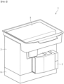
- FIG. 1 is a perspective view showing an appearance of a cooling and heating cabinet according to a first embodiment of the present invention
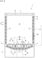
- FIG. 2 is a cross-sectional view of the cooling and heating cabinet according to the first embodiment of the present invention.
- a cooling and heating cabinet 1 includes an inner case 3, an outer case 4, a thermoelectric element module 60, a heat dissipating part 7, a separation panel 20, an agitating part 40, and a magnetic field generating part 30.
- the cooling and heating cabinet 1 according to the present embodiment may further include a lower case 6.
- the case 2 may have a substantially box shape.
- the case 2 may form an appearance of the cooling and heating cabinet 1.
- the case 2 may have a storage space 10 therein.
- the storage space 10 may store food or the like. Therefore, in order to maintain freshness or the like of food, it is important to keep a temperature of the storage space 10 constant.
- One side of the case 2 is opened so that a user may access the storage space 10.
- an upper surface of the case 2 may be opened.
- a cap 5 may be provided on the opened side of the case 2.
- the cap 5 may cover the one opened side of the case 2.
- the cap 5 may be detachably mounted to the case 2 and the user may access the storage space 10 by detaching the cap 5 from the case 2, and thereafter, the user may mount the cap 5 on the case 2 to close the storage space 10.
- the cap 5 may be a door hinged to the case 2. Further, when the upper surface of the case 2 is opened, the cap 5 may be a top cover.
- a sealing (not shown) may be provided between the cap 5 and the case 2 to thereby prevent cold air from leaking out of the storage space 10.
- the cap 5 may have a hermetically closed hollow 5a therein.
- the hollow 5a may act as a heat insulating material and prevent heat conduction through the cap 5 in a state in which the cap 5 is mounted on the case 2. This may help keep a temperature of the storage space 10 constant.
- the case 2 may have a dual-wall structure.
- the case 2 may include an inner case 3 and an outer case 4.
- the inner case 3 may have a storage space 10 therein.
- the inner case 3 may include an inner surface of the case 2.
- the outer case 4 may be disposed to surround the inner case 3.
- the outer case 4 may be spaced apart from the inner case 3 by a predetermined distance.
- An empty space may be provided between the inner case 3 and the outer case 4, and the empty space may be a heat insulating cavity 8.
- the insulating cavity 8 is in a closed state.
- the heat insulating cavity 8 is in a vacuum state, and here, the heat insulating cavity 8 being a vacuum cavity.
- a distance between the inner case 3 and the outer case 4, which corresponds to a width of the heat insulating cavity 8, is preferably constant in the entirety of the case 2.
- the present invention is not limited thereto.
- the heat insulating cavity 8 may serve as a heat insulating material between the outside of the casing 2 and the internal storage space 10 to maintain the temperature of the storage space 10 constant.
- a bottom surface 11 of the inner case 3 may include a planar portion 12 and sloped portion 13.
- the bottom surface 11 of the inner case 3 may refer to an inner lower surface of the inner case 3.
- the planar portion 12 may be a horizontally formed portion of the bottom surface 11.
- the planar portion 12 is preferably positioned at the center of the bottom surface 11 but is not limited thereto.
- the planar portion 12 may be formed to extend in a longitudinal direction of the cooling and heating cabinet 1.
- the agitating part 40 (to be described later) may be disposed on the planar portion 12.
- a width W1 of the planar portion 12 may be equal to or larger than a width W2 of the agitating part 40.
- the width W2 of the agitating part 40 may refer to a diameter of the agitating part 40.
- the entirety of the agitating part 40 may be positioned on the planar portion 12.
- the sloped portion 13 may be a sloped portion of the bottom surface 11.
- the sloped portion 13 may be formed to extend in the longitudinal direction of the cooling and heating cabinet 1 as with the planar portion 12.
- the sloped portion 13 may be connected to an edge of the planar portion 12. That is, the sloped portion 13 may extend from the edge of the planar portion 12.
- the sloped portion 13 may be provided as a pair, and each of the sloped portions 13 may be connected to both side edges of the planar portion 12.
- the sloped portion 13 may be formed to be sloped upwardly away from the planar portion 12. More specifically, the sloped portion 13 may be sloped in a direction in which a height of the sloped portion 13 increases away from the planar portion 12. That is, the planar portion 12 may be formed at the lowest position of the bottom surface 11 of the inner case 3.
- the sloped portions 13 connected to both sides of the planar portion 12 may be sloped in mutually opposite directions.
- One side of the sloped portion 13 may be connected to the planar portion 12 and the other side thereof may be connected to a side surface 14 of the inner case 3.
- a separate auxiliary planar portion (not shown) may be provided between the side surface 14 of the inner case 3 and the sloped portion 13.
- An outer edge of the sloped portion 13 may be positioned on an upper side than the stirring fan 41 of the agitating part 40.
- the outer edge of the sloped portion 13 may refer to a portion farthest from the planar portion 12 and may be an upper edge.
- air discharged in a radial direction from the stirring fan 41 may be reflected upward from the sloped portion 13. That is, the sloped portion 13 may serve to facilitate a flow of a discharge air current.
- a bottom surface of the outer case 4 may hav a shape corresponding to the bottom surface 11 of the inner case 3. That is, the bottom surface of the outer case 4 may also include a sloped portion and a planar portion. This may be an inevitable structure in order to maintain a certain interval of the heat insulating cavity 8 positioned between the inner case 3 and the outer case 4.
- thermoelectric element module 60 is disposed in the heat insulating cavity 8.
- the thermoelectric element module 60 may be disposed in an insulating cavity 8 positioned on a side surface portion or an upper surface portion of the case 2.
- thermoelectric element module 60 may be disposed in contact with the inner case 3 and the other side thereof may be in contact with the outer case 4. Accordingly, the thermoelectric element module 60 may perform heat conduction between the inner case 3 and the outer case 4.
- the thermoelectric element module 60 may maintain the storage space 10 at a low temperature in accordance with a refrigerating mode or at a high temperature in accordance with a heating mode according to a current flow direction. In the refrigerating mode and the heating mode, the current flow of the thermoelectric element module 60 may be opposite to each other.
- thermoelectric element module 60 absorbs heat at an electrode on the inner case 3 side and dissipates heat to an electrode on the outer case 4 side. As a result, the storage space 10 in the inner case 3 may be maintained at a low temperature.
- thermoelectric element module 60 may absorb heat at the electrode on the outer case 4 side and dissipates heat to the electrode on the inner case 3 side. As a result, the storage space 10 in the inner case 3 may be maintained at a high temperature.
- thermoelectric element module 60 A specific configuration of the thermoelectric element module 60 will be described in detail later.
- the heat insulating cavity 8 may have a heat transfer pipe 51.
- the heat transfer pipe 51 may further improve heat transfer performance based on the thermoelectric element module 60 between the inner case 3 and the outer case 4.
- the heat transfer pipe 51 may be in contact with and connected to the thermoelectric element module 60.
- the heat transfer pipe 51 may be mounted to surround an outer surface of the inner case 3.
- a plurality of heat transfer pipes 51 may be provided.
- the heat transfer pipe 51 may be disposed in direct contact with the inner case 3 and the outer case 4 and may be disposed between pipe fixing members 52.
- a case where the heat transfer pipe is fixed to the pipe fixing member 52 will be described as an example.
- the pipe fixing member 52 may be positioned in the heat insulating cavity 8.
- the pipe fixing member 52 may be disposed between the heat transfer pipe 51 and the inner case 3 and may be disposed between the heat transfer pipe 51 and the outer case 4.
- the pipe fixing member 52 may be integrally formed or divided into a plurality of pipes.
- the pipe fixing member 52 may be in contact with an outer surface of the heat transfer pipe 51.
- the pipe fixing member 52 may be in contact with the inner case 3 and the outer case 4.
- the pipe fixing member 52 fixes the heat transfer pipe 51, it may be easy to install the heat transfer pipe 51 in the heat insulating cavity 8.
- the heat transfer pipe 51 and the pipe fixing member 52 may be omitted.
- the heat dissipating part 7 may dissipate heat transferred to the thermoelectric element module 60.
- the heat dissipating part 7 may be disposed on an outer surface of the case 2. More specifically, the heat dissipating part 7 may be disposed on the outer surface of the outer case 4.
- the heat dissipating part 7 is preferably disposed on a circumferential surface of the outer case 4.
- the heat dissipating part 7 may be disposed at a position corresponding to the thermoelectric element module 60.
- the thermoelectric element module 60 may be disposed at a position overlapping the heat dissipating part 7. Accordingly, heat dissipated from the thermoelectric element module 60 may be rapidly dissipated by the heat dissipating part 7.
- the heat dissipating part 7 may include a heat sink (not shown) including a plurality of cooling fins and a cooling fan (not shown) for increasing heat exchange efficiency of the heat sink.
- the lower case 6 may be disposed below the case 2.
- An outer surface of the lower case 6 may be matched with the outer surface of the case 2.
- the lower case 6 may have a box shape whose upper surface is opened.
- the open upper surface of the lower case 6 may be covered by a lower surface of the case 2. More specifically, the opened upper surface of the lower case 6 may be covered by the lower surface of the outer case 4.
- a magnetic field generating part 30, which will be described later, may be disposed inside the lower case 6.
- a space for accommodating the magnetic field generating part 30 may be provided in the lower case 6.
- the magnetic field generating part 30 may be disposed inside the lower case 6.
- the magnetic field generating part 30 may be disposed between the case 2 and the lower case 6.
- the magnetic field generating part 30 may be disposed at an outer lower side of the case 2. Therefore, the heat insulating cavity 8 is positioned between the magnetic field generating part 30 and the agitating part 40.
- the magnetic field generating part 30 is arranged to overlap the agitating part 40.
- the magnetic field generating part 30 is disposed at a position corresponding to the agitating part 40.
- the magnetic field generating part 30 may include an external magnet 31 and a motor 32.
- the external magnet 31 may be rotated by driving the motor 32 and may form a rotating magnetic field.
- the magnet 42 of the agitating part 40 is rotated by the rotating magnetic field.
- the agitating part 40 may be disposed in the inner case 3.
- the agitating part 40 is disposed below the separation panel 20 to be described later.
- the agitating part 40 may be disposed on the planar portion 12 of the bottom surface 11 of the inner case 3.
- the agitating part 40 may be disposed in contact with the planar portion 12 and may be disposed to be spaced apart from the planar portion 12.
- the agitating part 40 is disposed to overlap the magnetic field generating part 30.
- the agitating part 40 is disposed at a position corresponding to the magnetic field generating part 30.
- the agitating part 40 stirs air to move and circulate air in the inner case 3. Accordingly, a temperature of the storage space 10 in the inner case 3 may be evenly distributed and performance of the cooling and heating cabinet 1 may be improved.
- the agitating part 40 includes a stirring fan 41 and a magnet 42.
- the stirring fan 41 and the magnet 42 may be integrally formed. It is also possible that the magnet 42 is mounted on a stirring body (not shown) formed integrally with the stirring fan 41.
- a shape of the magnet 42 is not limited.
- the magnet 42 may have a rod shape or a circular shape.
- the magnet 42 may be a bar magnet or a circular magnet.
- the magnet 42 may be rotatably disposed.
- the magnet 42 may be rotated by a rotating magnetic field generated by the magnetic field generating part 30.
- the magnet 42 may be provided below the stirring fan 41.
- the stirring fan 41 is rotated together with the magnet 42.
- the stirring fan 41 may rotate and intake air in an axial direction and discharge air in a radial direction.
- the stirring fan 41 may stir the air in the inner case 3, while being rotated.
- the stirring fan 41 may be disposed to face the sloped portion 13 with respect to a horizontal direction. That is, the stirring fan 41 may be disposed at a position lower than an upper edge of the sloped portion 13. Thus, air discharged from the stirring fan 41 may be reflected from the sloped portion 13 and flow upward.
- the cooling and heating cabinet 1 may further include a rotary shaft 43.
- the rotary shaft 43 may be disposed perpendicularly to penetrate through the agitating part 40.
- the agitating part 40 may rotate about the rotary shaft 43.
- the rotary shaft 43 itself may not rotate.
- the rotary shaft 43 may have one end connected to the separation panel 20 and the other end connected to the bottom surface 11 of the inner case 3. More specifically, the rotary shaft 43 may have one end connected to a lower surface of the separation panel 20 and the other end connected to the planar portion 12. Here, the rotary shaft 43 may be in direct contact with and connected to the separation panel 20 and the planar portion 12, or may be connected thereto with a separate fixing member (not shown) interposed therebetween.
- the rotary shaft 43 may also be connected to only any one of the separation panel 20 and the planar portion 12.
- the separation panel 20 is disposed above the agitating part 40.
- the separation panel 20 may be disposed inside the inner case 3.
- the separation panel 20 may be disposed horizontally.
- the separation panel 20 may be supported by the sloped portion 13.
- the separation panel 20 may be disposed to be in contact with the sloped portion 13. More specifically, both edges of the separation panel 20 may be disposed to be in contact with the sloped portion 13. Preferably, the separation panel 20 is disposed to be in contact with an upper end portion of the sloped portion 13.
- the separation panel 20 may be supported by a separate support member (not shown) protruding inward from the side surface 14 of the inner case 3, but preferably, the separation panel 20 is disposed to be in contact with the sloped portion 13 to secure the storage space 10 as large as possible.
- a width of the separation panel 20 may be equal to the sum of horizontal widths of the planar portion 12 and the sloped portion 13.
- the width of the separation panel 20 may be equal to a width of the storage space 10.
- the separation panel 20 may divide the inside of the inner case 3. More specifically, the separation panel 20 may divide the inside of the inner case 3 into the storage space 10 in which food may be stored and a stirring space accommodation space 15 in which the agitating part 40 is disposed.
- the storage space 10 may refer to an upper space of the separation panel 20 and the agitating part accommodation space 15 may refer to a lower space of the separation panel 20.
- a plurality of through holes 21 are provided in the separation panel 20.
- the through holes 21 provided in the separation panel 20 may be formed in a vertical direction.
- the separation panel 20 may guide air discharged into the storage space 10 to form a vertical upward air current.
- Air may flow from the upper side to the lower side of the separation panel 20 through some of the plurality of through holes 21 and air may flow from the lower side to the upper side of the separation panel 20 through the other of the plurality of through holes 21.
- the plurality of through holes 21 includes an intake hole 22 and a discharge hole 23.
- the intake hole 22 may intake air from the upper side to the lower side of the separation panel 20. That is, when the agitating part 40 is rotated, the air in the storage space 10 may be intaken into the agitating part accommodation space 15 through the intake hole 22.
- the intake hole 22 may overlap the agitating part 40. That is, the intake hole 22 may be formed at a position facing the agitating part 40. As a result, air may smoothly flow through the intake hole 22 and manufacturing unnecessary intake holes 22 may be prevented, thereby reducing manufacturing cost or the like.
- Air may be discharged through the discharge hole 23 from the lower side to the upper side of the separation panel 20. That is, when the agitating part 40 is rotated, the air in the agitating part accommodation space 15 may be discharged into the storage space 10 through the discharge hole 23.
- the discharge hole 23 may overlap with the sloped portion 13. That is, the discharge hole 23 may be formed at a position facing the sloped portion 13. As a result, the flow of air through the discharge hole 23 may be smooth, and unnecessary discharge holes 23 may be prevented from being produced, thereby reducing manufacturing costs and the like.
- the electrode of the thermoelectric element module 60 on the inner case 3 side may absorb heat and the electrode on the outer case 4 side may dissipate heat.
- the heat dissipating part 7 may rapidly dissipate heat emitted from the electrode on the outer case 4 side of the thermoelectric element module 60.
- the electrode of the thermoelectric element module 60 on the inner case 3 side may absorb heat to cool the inner case 3.
- the heat of the inner case 3 may be quickly transferred to the thermoelectric element module 60 by the heat transfer pipe 51 surrounding the outer surface of the inner case 3.
- a temperature of the storage space 10 may be lowered.
- the storage space 10 is heat-insulated from the outside due to the structure of the single cavity 8 to maintain a low temperature of the storage space 10.
- thermoelectric element module 60 In the heating mode, a current may be applied to the thermoelectric element module 60 in the opposite direction, and thus, a direction of heat conduction may be reversed.
- the external magnet 31 may rotate to generate a rotating magnetic field.
- the magnet 42 of the agitating part 40 may be rotated around the rotary shaft 43 together with the stirring fan 41 by the rotating magnetic field.
- a magnetic field generated by the magnetic field generating part 30 reaches the agitating part 40 beyond the vacuum cavity 8, and thus, the agitating part 40 is advantageously rotated, while the structure of the vacuum cavity 8 is maintained.
- air in the storage space 10 may be intaken into the agitating part accommodation space 15 through the intake hole 22 of the separation panel 20.
- the intaken air may be intaken in the axial direction of the stirring fan 41 and discharged in the radial direction.
- the air discharged in the radial direction from the stirring fan 41 may be reflected upward from the sloped portion 13 and may be discharged to the storage space 15 through the discharge hole 23.
- the air in the inner case 3 may flow to form a circulating air current and the temperature of the storage space 10 may be evenly distributed.
- the structure of the sloped portion 13 and the through hole 21 of the separation panel 20 may guide a flow direction of the air to further increase the effect of stirring, and the temperature in the storage space 10 may be distributed rapidly and evenly.
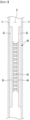
- FIG. 3 is a view illustrating a thermoelectric element module according to an example.
- thermoelectric element module 60 a detailed configuration of the thermoelectric element module 60 will be described with reference to FIG. 3 .
- thermoelectric element module 60 may be disposed in the heat insulating cavity 8 and may be disposed such that one side thereof is in contact with the inner case 3 and the other side thereof is in contact with the outer case 4. Heat may be absorbed on the one side of the thermoelectric element module 60 and heat may be dissipated on the other side. Conversely, heat dissipation may be performed on the one side of the thermoelectric element module 60, and heat absorption may be performed on the other side.
- the thermoelectric element module 60 may include ceramic substrates 61 and 62, metal electrodes 63 and 64, and a plurality of semiconductor thermoelectric elements 65.
- the ceramic substrates 61 and 62 and the metal electrodes 63 and 64 may be arranged perpendicularly.
- the ceramic substrates 61 and 62 may include a first ceramic substrate 61 provided in contact with the inner case 3 and a second ceramic substrate 62 provided in contact with the outer case 4.
- the first ceramic substrate 61 and the second ceramic substrate 62 may be spaced apart from each other in a facing manner. Sizes of the first ceramic substrate 61 and the second ceramic substrate 62 may be equal.
- the metal electrodes 63 and 64 may be disposed between the first ceramic substrate 61 and the second ceramic substrate 62. Sizes of the metal electrodes 63 and 64 may be smaller than the sizes of the ceramic substrates 61 and 62.
- the metal electrodes 63 and 64 may be formed of a metal plate, and current may be applied to the metal electrodes 63 and 64.
- the metal electrodes 63 and 64 may be connected to a DC power source. When connection of the metal electrodes 63 and 64 to the DC power source is reversed, a direction of a current applied to the thermoelectric element module 60 may be reversed.
- the metal electrodes 63 and 64 may include a first metal electrode 63 provided in contact with the first ceramic substrate 61 and a second metal electrode 64 provided in contact with the second ceramic substrate 62.
- the first metal electrode 63 and the second metal electrode 64 may be spaced apart from each other in a facing manner. Sizes of the first metal electrode 63 and the second metal electrode 64 may be equal.
- the plurality of semiconductor thermoelectric elements 65 may include N-type semiconductor elements and P-type semiconductor elements which are alternately arranged.
- the plurality of semiconductor thermoelectric elements 65 may be alternately connected to the first metal electrode 63 and the second metal electrode 64 through both end portion side surfaces of the semiconductor thermoelectric elements 65, and thus, all the semiconductor elements 33 may be electrically connected in series.
- thermoelectric element module 60 may absorb heat by the first metal electrode 61 and dissipate heat by the second metal electrode 62. As a result, a temperature of the storage space 10 in the inner case 3 may be maintained low.
- thermoelectric element module 60 absorbs heat by the second metal electrode 62 and dissipates heat by the first metal electrode 61. As a result, the storage space 10 in the inner case 3 may be maintained at a high temperature.
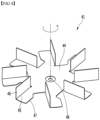
- FIG. 4 is a perspective view showing an example of a stirring fan.
- the stirring fan 41 may include a central portion 44, a peripheral portion 45, a blade 46, and a protrusion 47.
- a shape of the central portion 44 is not limited.
- the central portion 44 may have a substantially disc shape.
- a hole 48 into which the rotary shaft 43 may be inserted may be formed at the center of the central portion 44.
- the peripheral portion 45 may protrude radially from the edge of the central portion 44.
- a plurality of peripheral portions 45 may be provided, and the peripheral portions 45 may be spaced apart from each other by a predetermined distance.
- a blade 46 may be provided on one side of each peripheral portion 45 and a protrusion 47 may be provided on the other side.
- the blade 46 may be formed by bending a portion of the peripheral portion 46.
- the blade 46 may be bent to face upward.
- the blade 46 may be provided at a predetermined angle with the peripheral portion 45.
- the blade 46 may have a free curved surface.
- the protrusion 47 may protrude from the peripheral portion 45 in a circumferential direction. More specifically, the protrusion 47 may protrude in the circumferential direction of the peripheral portion 45 when the stirring fan 41 rotates. That is, a rotation direction of the stirring fan 41 may rotate so that each blade 46 moves toward the protruding direction of the protrusion 47. For example, the stirring fan 41 as shown in FIG. 4 may rotate in a counterclockwise direction.
- the shape and configuration of the stirring fan 41 are merely examples, and the shape and configuration of the stirring fan 41 may be changed as necessary.
- FIG. 5 is a plan view showing an example of a separation panel.
- a detailed structure of the separation panel 20 will be described with reference to FIG. 5 .
- the separation panel 20 may have a substantially rectangular plate shape. The edges of the separation panel 20 may be rounded.
- the separation panel 20 includes a first region 24 disposed to face the planar portion 12 of the inner case 3 and a second region 25 disposed to face the sloped portion 13 of the inner case 3.
- a width of the first region 24 may be equal to a width W1 of the planar portion 12 and a width of the second region 25 may be equal to a width of the sloped portion 13.
- the second region 25 may be provided as a pair and the first region 24 may be positioned between the second regions 25.
- the second regions 25 may be spaced apart from each other.
- a plurality of through holes 21 may be formed in the separation panel 20, and the through holes 21 may include the intake hole 22 and the discharge hole 23.
- the intake hole 22 may be formed in the first region 24 of the separation panel 20.
- the intake hole 22 may overlap the agitating part 40. More specifically, the intake hole 22 may overlap a virtual circle C formed as the agitating part 40 rotates. A diameter of the virtual circle C may be equal to the width W2 of the agitating part 30.
- a plurality of intake holes 22 may gather to form an intake hole group 22a. More specifically, a plurality of intake holes 22 may gather to form a single intake hole group 22a.
- the intake hole group 22a may overlap the agitating part 40.
- the intake hole group 22a may have a substantially circular shape.
- the discharge hole 23 may be formed in the second region 25 of the separation panel 20.
- the discharge hole 23 may be formed all over the second region 25, but in order to prevent formation of an unnecessary discharge hole 23, the discharge hole 23 is preferably formed only in a portion of the second region 25.
- a plurality of discharge holes 23 may gather to form at least one pair of discharge hole groups 23a and 23b.
- a pair of discharge hole groups 23a and 23b may be formed in the separation panel 20, and the discharge hole groups 23a and 23b may be positioned in the second regions 25, respectively.
- first discharge hole group 23a may be formed in one second region 25a and the second discharge hole group 23b may be formed in the other second region 25b. That is, the first discharge hole group 23a may be positioned to face one sloped portion 13, and the second discharge hole group 23b may be positioned to face the other sloped portion 13.
- the numbers of the discharge holes 23 constituting the first discharge hole group 23a and the second discharge hole group 23b may be different from each other.
- the first discharge hole group 23a and the second discharge hole group 23b may be positioned to be eccentric in the mutually opposite directions with respect to the intake hole group 22a.
- the intake hole group 22a may be positioned at a central portion of the separation panel 20
- the first discharge hole group 23a may be positioned at a rear portion of the separation panel 20
- the second discharge hoe group 23b may be positioned at a front portion of the separation panel.
- Each of the discharge hole groups 23a and 23b may be formed at a position where only one diagonal line D1 among a pair of diagonal lines D1 and D2 of the discharge panel 20 passes. That is, one diagonal line D1 among the pair of diagonal lines D1 and D2 of the discharge panel 20 may pass through the discharge hole groups 23a and 23b and the other diagonal line D2 may not pass through the discharge hole groups 23a and 23b.
- the discharge hole groups 23a and 23b may be formed at positions near the blade 46 and the protrusion 47 of the stirring fan 41 in a width direction of the separation panel 20 when the stirring fan 41 rotates. That is, when the stirring fan 41 is rotated, the blade 46 and the protrusion 47 may move toward the discharge hole groups 23a and 23b with respect to the width direction of the separation panel 20.
- the stirring fan 41 rotates in a counterclockwise direction.
- the blades 46 and the protrusion 47 of the stirring fan 41 may move in a direction toward the first discharge hole group 23a on the rear side and may move in a direction toward the second discharge hole group 23b on the front side.
- the discharge holes 23 are formed only in a portion of the second region 25, rather than being formed in the entire second region 25 of the separation panel 20, the air discharged from the agitating part 40 may be efficiently discharged through the discharge holes 23.
- FIG. 6 is a cross-sectional view of a cooling and heating cabinet according to a second embodiment of the present invention.
- the cooling and heating cabinet 1 according to the second embodiment is the same as the cooling and heating cabinet according to the first embodiment except for support portions 43a and 43b, and thus, the same contents as those described above will be omitted and only differences will be mainly described.
- the cooling and heating cabinet 1 may further include the support portions 43a and 43b instead of the rotary shaft 43.
- the support portions 43a and 43b may include an upper support portion 43a and a lower support portion 43b.
- the upper support portion 43a may support the agitating part 40 from an upper side and the lower support portion 43b may support the agitating part 40 from a lower side.
- the upper support portion 43a and the lower support portion 43b may be arranged in a straight line.
- the upper support portion 43a and the lower support portion 43b may be disposed to be in contact with the center of the agitating part 40.
- a recessed portion may be formed at a portion of the upper surface and the lower surface of the agitating part 40 which is in contact with the support portions 43a and 43b so that the agitating part 40 is not separated from the support portions 43a and 43b.
- An upper end of the upper support portion 43a may be connected to the separation panel 20 and a lower end thereof may be connected to the agitating part 40.
- the upper end of the lower support portion 43b may be connected to the agitating part 40 and the lower end may be connected to the planar portion 12.
- the support portions 43a and 43b may have a conical shape having a diameter decreased toward the agitating part 40. That is, a diameter of the upper support portion 43a may be decreased from the upper side to the lower side, and a diameter of the lower support portion 43b may be decreased from the lower side to the upper side.
- the end portion connected to the agitating part 40 have a very small diameter, reducing frictional contact between the support portions 43a and 43b and the agitating part 40, and thus, the agitating part 40 may smoothly rotate.
- the end portion connected to the separation panel 20 or the planar portion 12 may have a large diameter so as to be stably fixed to the separation panel 20 or the planar portion 12.
- the support portions 43a and 43b may not rotate.
- FIG. 7 is a cross-sectional view of a cooling and heating cabinet according to a third embodiment of the present invention.
- the cooling and heating cabinet 1 according to the third embodiment is the same as the cooling and heating cabinet according to the first embodiment except for a guide portion 44, and thus, the same contents as those described above will be omitted and only differences will be mainly described.
- the cooling and heating cabinet 1 may further include the guide portion 44.
- the guide portion 44 may have a hollow cylindrical shape.
- the guide portion 44 may be spaced apart from an outer circumference of the agitating part 40 and surround the agitating part 40.
- the guide portion 44 may be provided as a pair of partition walls arranged to extend in a longitudinal direction of the cooling and heating cabinet 1.
- the agitating part 40 may be positioned between the pair of guide portions 44.
- a space in which the agitating part 40 is disposed may be formed in the guide portion 44.
- the guide portion 44 may be perpendicularly disposed between the separation panel 20 and the bottom surface 11 of the inner case 3. More specifically, the guide portion 44 may be disposed perpendicularly between the separation panel 20 and the planar portion 12.
- An upper portion of the guide portion 44 may be in contact with the separation panel 20 and a lower portion thereof may be in contact with the planar portion 12.
- the separation panel 20 may be supported by the sloped portions 13 at both ends thereof.
- a sagging phenomenon may occur at the central portion of the separation panel 20.
- food or the like will fall and hit the separation panel 20 to damage the separation panel 20.
- the guide portion 44 may advantageously prevent such a possibility by supporting the central portion of the separation panel 20.
- a plurality of auxiliary through holes 45 may be provided in the guide portion 44.
- the auxiliary through hole 45 may be provided in a horizontal direction.
- the guide portion 44 may guide air discharged from the agitating part 40 to form a horizontal air current.
- the guide portion 44 may be disposed to be in contact between the intake hole 22 and the discharge hole 23 of the separation panel 20. Accordingly, the air in the storage space 10 may flow into the guide portion 44 through the intake hole 22, may flow in a diameter direction of the agitating part 40 through the auxiliary through hole 45, and may be reflected from the sloped portion 13 so as to be discharged to the discharge hole 23.
- the guide portion 44 may prevent the agitating part 40 from being released from a predetermined position.
- FIG. 8 is a cross-sectional view of a cooling and heating cabinet according to a fourth embodiment of the present invention.
- An inner depressed portion 3a may be provided in the inner case 3 of the cooling and heating cabinet 1 according to the present embodiment.
- the inner depressed portion 3a may be formed such that at least a portion of the planar portion 12 is depressed downward.
- the outer case 4 may have an outer depressed portion 4a corresponding to the inner depressed portion 3a. At least a portion of the inner depressed portion 3a may be positioned inside the outer depressed portion 4a.
- the inner depressed portion 3a and the outer depressed portion 4a may have a hollow cylindrical shape.
- the inner depressed portion 3a and the outer depressed portion 4a may be spaced apart from each other by a predetermined distance.
- the heat insulating cavity 8 may be positioned between the inner depressed portion 3a and the outer depressed portion 4a. Therefore, the cooling and heating cabinet 1 according to the present embodiment may also maintain heat insulating performance by the structure of the heat insulating cavity 8.
- a vertical protrusion 6a may be provided in the lower case 6 of the cooling and heating cabinet 1 according to the present embodiment.
- the vertical protrusion 6a may be arranged to surround a circumference of a magnetic field generating part 30'.
- the vertical protrusion 6a may be a housing of an integral motor.
- the vertical protrusion 6a may have a hollow cylindrical shape.
- the vertical protrusion 6a may protrude perpendicularly upward from a lower surface of the lower case 6.
- An upper end of the vertical protrusion 6a may be in contact with the lower surface of the case 2. More specifically, the upper end of the vertical protrusion 6a may be in contact with the lower surface of the outer case 4. Accordingly, the vertical protrusion 6a may serve to support the case 2 from below.
- An agitating part 40' of the cooling and heating cabinet 1 may include a stirring fan 41, a shaft 71 and a rotor 72.
- the stirring fan 41 may be positioned outside the inner depressed portion 3a.
- the stirring fan 41 may be positioned above the inner depressed portion 3a.
- the shaft 71 may be connected to the stirring fan 41 and the stirring fan 41 may rotate together with the shaft 71.
- the shaft 71 may be connected to a lower side of the stirring fan 41.
- the shaft 71 may be disposed perpendicularly. At least a portion of the shaft 71 may be positioned inside the inner depressed portion 3a.
- a position of the shaft 71 may be fixed by a bearing. When the stirring fan 41 rotates, the shaft 71 may rotate together.
- the rotor 72 may be disposed to surround at least a portion of the shaft 71 on a lower side of the stirring fan 41 and may be positioned inside the inner depressed portion 3a.
- the rotor 72 may rotate together with the shaft 71.
- the rotor 72 may include a magnet 42' and a pair of end plates 74 and 75.
- the magnet 42' may be arranged to extend up and down.
- An upper end of the magnet 42' is supported by the first end plate 74, and a lower end of the magnet 42' is supported by the second end plate 75. That is, the end plates 74 and 75 may prevent the magnet 42' from moving up and down.
- the magnet 42' may be rotated by a rotating magnetic field generated by the magnetic field generating part 30', whereby the agitating part 40 may rotate as a whole.
- the magnetic field generating part 30' of the cooling and heating cabinet 1 may be provided on the outer circumference of the outer depressed portion 4a.
- the heat insulating cavity 8 may be positioned between the magnetic field generating part 30' and the rotor 72.
- the magnetic field generating part 30' of the cooling and heating cabinet 1 may include a stator core 77 and a coil 78.
- the stator core 77 may be disposed to be spaced apart from an outer circumference of the rotor 72.
- the stator core 77 may be fixed to a vertical protrusion 6a.
- the coil 78 may be provided in the stator core 77.
- An alternating current may be applied to the coil 78 to generate a rotating magnetic field.
- the magnet 42' of the rotor 72 may be rotated by the rotating magnetic field.
- the magnetic field generated by the coil 78 of the magnetic field generating part 30 may reach the rotor 72 beyond the vacuum cavity 8, so that the agitating part 40 may be advantageously rotated, while the structure of the vacuum cavity 8 is maintained.
- the agitating part 40' and the magnetic field generating part 30' may be a case-integrated type motor. That is, the cooling and heating cabinet apparatus 1 according to the present embodiment may be a cooling and heating cabinet apparatus including an integrated motor.
- FIG. 9 is a view showing another example of a separation panel.
- the separation panel 20 may have a lattice structure.
- the discharge hole and the intake hole may not be distinguished from each other in the through holes 21 provided in the separation panel 21, but the separation panel 20 may be simply manufactured and the area of the through holes is large.
- the separation panel 20 may include a plurality of first ribs 28 and a plurality of second ribs 29.
- the first ribs 28 and the second ribs 29 may cross each other at right angles.
- the plurality of first ribs 28 may be arranged in parallel and spaced apart from each other by the same spacing.
- the plurality of second ribs 29 may be arranged in parallel and spaced apart from each other by the same spacing.
- Each through hole 21 may be defined as a space surrounded by a pair of first ribs 28 adjacent to each other and a pair of second ribs 29 adjacent to each other.
- the separation panel 20 may also have a mesh structure.
Landscapes
- Engineering & Computer Science (AREA)
- Physics & Mathematics (AREA)
- Thermal Sciences (AREA)
- Mechanical Engineering (AREA)
- General Engineering & Computer Science (AREA)
- Chemical & Material Sciences (AREA)
- Combustion & Propulsion (AREA)
- Transportation (AREA)
- Chemical Kinetics & Catalysis (AREA)
- Food Science & Technology (AREA)
- Devices That Are Associated With Refrigeration Equipment (AREA)
- Cold Air Circulating Systems And Constructional Details In Refrigerators (AREA)
Description
- The present invention relates to a cooling and heating cabinet having a heat insulation cavity.
- A cooling and heating cabinet is provided with a storage space for storing food therein, so that a temperature of the storage space may be maintained at a low or high temperature according to a user selection. In particular, a cooling and heating cabinet for a vehicle is installed in the interior of a vehicle to temporarily keep drinks and small amounts of food.
- Since capacity of the cooling and heating cabinet for a vehicle is relatively small, a cooling method using a thermoelectric element, rather than using a cooling method using circulation of a refrigerant is generally used. The thermoelectric element is an electronically cooled substrate utilizing the Peltier effect. The Peltier effect refers to a phenomenon in which an electrical current passing through a junction between two types of metal absorbs heat at one terminal and generates heat at the other terminal depending on a direction of the current.
- According to this cooling method, heat inside the cooling and heating cabinet for a vehicle is absorbed by a heat absorption terminal, and thus, a temperature inside the cooling and heating cabinet may be maintained at a constant temperature or lower. In addition, if the direction of the current flowing through the thermoelectric element is reversed, heat emitted from a heat generation terminal may be transferred to the inside of the cooling and heating cabinet for the vehicle, so that the temperature inside the cooling and heating cabinet may be maintained at a predetermined temperature or higher.
- Meanwhile, a cooling part such as a heat dissipation plate or a cooling fan may be provided in the cooling and heating cabinet for a vehicle to cool high temperature heat generated from the heat generation terminal.
- However, the cooling and heating cabinet according to the related art has a problem in that time taken for the inside of a refrigerating chamber to reach a target temperature using only the thermoelectric element is long. In addition, cold air falls and warm air rises inside the refrigerating chamber, resulting in that the temperature of the refrigerating chamber is not uniform.
- Further related technologies are disclosed in
DE 297 16 137 U1 ,FR 2 435 680 A1JP H08 14724 A DE 10 2015 006560 A1DE 10 2015 006562 A1US 3733 836 A ,JP 2005 269709 A - It is an object of the present invention to provide a cooling and heating cabinet capable of keeping a temperature of a storage space constant.
- Another object of the present invention is to provide a cooling and heating cabinet capable of making a temperature of a storage space to be distributed uniformly.
- To solve the technical problem as described above, there is provided a cooling and heating cabinet including: an inner case having a storage space therein; an outer case disposed to surround the inner case, a heat insulating cavity being provided between the outer case and the inner case, and wherein the heat insulating cavity is a single vacuum cavity; a thermoelectric element module disposed in the heat insulating cavity; a separation panel disposed inside the inner case and having a plurality of through holes, the plurality of through holes including an intake hole and a discharge hole; an agitating part disposed between a bottom surface of the inner case and the separation panel and having a magnet and a stirring fan rotating together with the magnet; and a magnetic field generating part disposed outside the outer case and generating a magnetic field to cause the magnet to be rotated.
- The bottom surface of the inner case may include: a planar portion on which the agitating part is disposed; and a sloped portion connected to an edge of the planar portion and upwardly sloped in a direction away from the planar portion.
- A width of the planar portion may be larger than a width of the agitating part.
- An outer edge of the sloped portion may be positioned above the stirring fan.
- The separation panel may be supported by the sloped portion and disposed horizontally.
- The agitating part may include: a shaft connected to the stirring fan; and a rotor disposed to surround at least a portion of the shaft on a lower side of the stirring fan and having the magnet to rotate the shaft. The magnetic field generating part may include: a stator core disposed to be spaced apart from an outer circumference of the rotor; and a coil provided on the stator core and generating a magnetic field by an alternating current applied thereto.
- At least a portion of the planar portion may be depressed downward to form an inner depressed portion, the outer case may have an outer depressed portion corresponding to the inner depressed portion, the heat insulation cavity being provided between the inner depressed portion and the outer depressed portion, the rotor may be disposed in the inner depressed portion, and the magnetic field generating part may be provided on an outer circumference of the outer depressed portion.
- The magnet may have a bar shape or a circular shape, and the magnetic field generating part may include: a motor; and an external magnet rotated by the motor to generate a magnetic field.
- The cooling and heating cabinet may further include: a rotary shaft penetrating through the agitating part and disposed to be perpendicular to the agitating part.
- The cooling and heating cabinet may further include: a lower support portion supporting a lower side of the agitating part; and an upper support portion supporting an upper side of the agitating part, wherein the lower support portion and the upper support portion may have a conical shape having a diameter reduced toward the agitating part.
- The cooling and heating cabinet may further include: a guide portion disposed to be perpendicular between the bottom surface of the inner case and the separation panel, wherein the guide portion may have a plurality of auxiliary through holes.
- The plurality of through holes includes:
the intake hole overlapping the agitating part and allowing air to be intaken from an upper side of the separation panel to a lower side of the separation panel; and the discharge hole facing the sloped portion and allowing air to be discharged from the lower side of the separation panel to the upper side of the separation panel. - The separation panel may have an intake hole group having a plurality of intake holes and a discharge hole group having a plurality of discharge holes, and a pair of discharge hole groups may be spaced apart from each other with the intake hole group interposed therebetween.
- The separation panel may have a lattice structure.
- According to the present invention, since the storage space is insulated from the outside by the insulating cavity structure of the case, a temperature of the storage space may be maintained constant.
- In addition, since the agitating part is rotated by a magnetic field generated by the magnetic field generating part, the agitating part may be rotated, while maintaining the heat insulating cavity structure, and the temperature of the storage space may be evenly distributed by stirring air by the agitating part.
-
-
FIG. 1 is a perspective view showing an appearance of a cooling and heating cabinet according to a first embodiment of the present invention. -
FIG. 2 is a cross-sectional view of a cooling and heating cabinet according to a first embodiment of the present invention. -
FIG. 3 is a view illustrating a thermoelectric element module according to an example. -
FIG. 4 is a perspective view showing an example of a stirring fan. -
FIG. 5 is a plan view showing an example of a separation panel. -
FIG. 6 is a cross-sectional view of a cooling and heating cabinet according to a second embodiment of the present invention. -
FIG. 7 is a cross-sectional view of a cooling and heating cabinet according to a third embodiment of the present invention. -
FIG. 8 is a cross-sectional view of a cooling and heating cabinet according to a fourth embodiment of the present invention. -
FIG. 9 is a view showing another example of a separation panel. - Hereinafter, specific embodiments of the present invention will be described in detail with reference to the accompanying drawings.
-
FIG. 1 is a perspective view showing an appearance of a cooling and heating cabinet according to a first embodiment of the present invention, andFIG. 2 is a cross-sectional view of the cooling and heating cabinet according to the first embodiment of the present invention. - Referring to
FIGS. 1 and2 , a cooling andheating cabinet 1 according to the present embodiment includes an inner case 3, anouter case 4, athermoelectric element module 60, aheat dissipating part 7, aseparation panel 20, anagitating part 40, and a magneticfield generating part 30. The cooling andheating cabinet 1 according to the present embodiment may further include alower case 6. - The
case 2 may have a substantially box shape. Thecase 2 may form an appearance of the cooling andheating cabinet 1. - The
case 2 may have astorage space 10 therein. Thestorage space 10 may store food or the like. Therefore, in order to maintain freshness or the like of food, it is important to keep a temperature of thestorage space 10 constant. - One side of the
case 2 is opened so that a user may access thestorage space 10. For example, an upper surface of thecase 2 may be opened. - A
cap 5 may be provided on the opened side of thecase 2. Thecap 5 may cover the one opened side of thecase 2. - The
cap 5 may be detachably mounted to thecase 2 and the user may access thestorage space 10 by detaching thecap 5 from thecase 2, and thereafter, the user may mount thecap 5 on thecase 2 to close thestorage space 10. - The
cap 5 may be a door hinged to thecase 2. Further, when the upper surface of thecase 2 is opened, thecap 5 may be a top cover. - A sealing (not shown) may be provided between the
cap 5 and thecase 2 to thereby prevent cold air from leaking out of thestorage space 10. - The
cap 5 may have a hermetically closed hollow 5a therein. The hollow 5a may act as a heat insulating material and prevent heat conduction through thecap 5 in a state in which thecap 5 is mounted on thecase 2. This may help keep a temperature of thestorage space 10 constant. - The
case 2 may have a dual-wall structure. In more detail, thecase 2 may include an inner case 3 and anouter case 4. - The inner case 3 may have a
storage space 10 therein. The inner case 3 may include an inner surface of thecase 2. - The
outer case 4 may be disposed to surround the inner case 3. Theouter case 4 may be spaced apart from the inner case 3 by a predetermined distance. - An empty space may be provided between the inner case 3 and the
outer case 4, and the empty space may be aheat insulating cavity 8. The insulatingcavity 8 is in a closed state. Theheat insulating cavity 8 is in a vacuum state, and here, theheat insulating cavity 8 being a vacuum cavity. - A distance between the inner case 3 and the
outer case 4, which corresponds to a width of theheat insulating cavity 8, is preferably constant in the entirety of thecase 2. However, the present invention is not limited thereto. - The
heat insulating cavity 8 may serve as a heat insulating material between the outside of thecasing 2 and theinternal storage space 10 to maintain the temperature of thestorage space 10 constant. - A
bottom surface 11 of the inner case 3 may include aplanar portion 12 and slopedportion 13. Here, thebottom surface 11 of the inner case 3 may refer to an inner lower surface of the inner case 3. - The
planar portion 12 may be a horizontally formed portion of thebottom surface 11. Theplanar portion 12 is preferably positioned at the center of thebottom surface 11 but is not limited thereto. Theplanar portion 12 may be formed to extend in a longitudinal direction of the cooling andheating cabinet 1. - The agitating part 40 (to be described later) may be disposed on the
planar portion 12. A width W1 of theplanar portion 12 may be equal to or larger than a width W2 of the agitatingpart 40. Here, the width W2 of the agitatingpart 40 may refer to a diameter of the agitatingpart 40. Thus, the entirety of the agitatingpart 40 may be positioned on theplanar portion 12. - The sloped
portion 13 may be a sloped portion of thebottom surface 11. The slopedportion 13 may be formed to extend in the longitudinal direction of the cooling andheating cabinet 1 as with theplanar portion 12. - The sloped
portion 13 may be connected to an edge of theplanar portion 12. That is, the slopedportion 13 may extend from the edge of theplanar portion 12. The slopedportion 13 may be provided as a pair, and each of the slopedportions 13 may be connected to both side edges of theplanar portion 12. - The sloped
portion 13 may be formed to be sloped upwardly away from theplanar portion 12. More specifically, the slopedportion 13 may be sloped in a direction in which a height of the slopedportion 13 increases away from theplanar portion 12. That is, theplanar portion 12 may be formed at the lowest position of thebottom surface 11 of the inner case 3. - The
sloped portions 13 connected to both sides of theplanar portion 12 may be sloped in mutually opposite directions. - One side of the sloped
portion 13 may be connected to theplanar portion 12 and the other side thereof may be connected to aside surface 14 of the inner case 3. Alternatively, a separate auxiliary planar portion (not shown) may be provided between theside surface 14 of the inner case 3 and the slopedportion 13. - An outer edge of the sloped
portion 13 may be positioned on an upper side than the stirringfan 41 of the agitatingpart 40. In this case, the outer edge of the slopedportion 13 may refer to a portion farthest from theplanar portion 12 and may be an upper edge. - Accordingly, air discharged in a radial direction from the stirring
fan 41 may be reflected upward from the slopedportion 13. That is, the slopedportion 13 may serve to facilitate a flow of a discharge air current. - A bottom surface of the
outer case 4 may hav a shape corresponding to thebottom surface 11 of the inner case 3. That is, the bottom surface of theouter case 4 may also include a sloped portion and a planar portion. This may be an inevitable structure in order to maintain a certain interval of theheat insulating cavity 8 positioned between the inner case 3 and theouter case 4. - Meanwhile, the
thermoelectric element module 60 is disposed in theheat insulating cavity 8. In more detail, thethermoelectric element module 60 may be disposed in an insulatingcavity 8 positioned on a side surface portion or an upper surface portion of thecase 2. - One side of the
thermoelectric element module 60 may be disposed in contact with the inner case 3 and the other side thereof may be in contact with theouter case 4. Accordingly, thethermoelectric element module 60 may perform heat conduction between the inner case 3 and theouter case 4. - The
thermoelectric element module 60 may maintain thestorage space 10 at a low temperature in accordance with a refrigerating mode or at a high temperature in accordance with a heating mode according to a current flow direction. In the refrigerating mode and the heating mode, the current flow of thethermoelectric element module 60 may be opposite to each other. - In the refrigerating mode, the
thermoelectric element module 60 absorbs heat at an electrode on the inner case 3 side and dissipates heat to an electrode on theouter case 4 side. As a result, thestorage space 10 in the inner case 3 may be maintained at a low temperature. - In the heating mode, the
thermoelectric element module 60 may absorb heat at the electrode on theouter case 4 side and dissipates heat to the electrode on the inner case 3 side. As a result, thestorage space 10 in the inner case 3 may be maintained at a high temperature. - A specific configuration of the
thermoelectric element module 60 will be described in detail later. - Meanwhile, the
heat insulating cavity 8 may have aheat transfer pipe 51. Theheat transfer pipe 51 may further improve heat transfer performance based on thethermoelectric element module 60 between the inner case 3 and theouter case 4. - The
heat transfer pipe 51 may be in contact with and connected to thethermoelectric element module 60. Theheat transfer pipe 51 may be mounted to surround an outer surface of the inner case 3. A plurality ofheat transfer pipes 51 may be provided. - The
heat transfer pipe 51 may be disposed in direct contact with the inner case 3 and theouter case 4 and may be disposed betweenpipe fixing members 52. Hereinafter, a case where the heat transfer pipe is fixed to thepipe fixing member 52 will be described as an example. - The
pipe fixing member 52 may be positioned in theheat insulating cavity 8. Thepipe fixing member 52 may be disposed between theheat transfer pipe 51 and the inner case 3 and may be disposed between theheat transfer pipe 51 and theouter case 4. - The
pipe fixing member 52 may be integrally formed or divided into a plurality of pipes. - The
pipe fixing member 52 may be in contact with an outer surface of theheat transfer pipe 51. Thepipe fixing member 52 may be in contact with the inner case 3 and theouter case 4. - Since the
pipe fixing member 52 fixes theheat transfer pipe 51, it may be easy to install theheat transfer pipe 51 in theheat insulating cavity 8. - The
heat transfer pipe 51 and thepipe fixing member 52 may be omitted. - Meanwhile, the
heat dissipating part 7 may dissipate heat transferred to thethermoelectric element module 60. Theheat dissipating part 7 may be disposed on an outer surface of thecase 2. More specifically, theheat dissipating part 7 may be disposed on the outer surface of theouter case 4. Theheat dissipating part 7 is preferably disposed on a circumferential surface of theouter case 4. - The
heat dissipating part 7 may be disposed at a position corresponding to thethermoelectric element module 60. Thethermoelectric element module 60 may be disposed at a position overlapping theheat dissipating part 7. Accordingly, heat dissipated from thethermoelectric element module 60 may be rapidly dissipated by theheat dissipating part 7. - The
heat dissipating part 7 may include a heat sink (not shown) including a plurality of cooling fins and a cooling fan (not shown) for increasing heat exchange efficiency of the heat sink. - The
lower case 6 may be disposed below thecase 2. An outer surface of thelower case 6 may be matched with the outer surface of thecase 2. - The
lower case 6 may have a box shape whose upper surface is opened. The open upper surface of thelower case 6 may be covered by a lower surface of thecase 2. More specifically, the opened upper surface of thelower case 6 may be covered by the lower surface of theouter case 4. - A magnetic
field generating part 30, which will be described later, may be disposed inside thelower case 6. A space for accommodating the magneticfield generating part 30 may be provided in thelower case 6. - The magnetic
field generating part 30 may be disposed inside thelower case 6. The magneticfield generating part 30 may be disposed between thecase 2 and thelower case 6. The magneticfield generating part 30 may be disposed at an outer lower side of thecase 2. Therefore, theheat insulating cavity 8 is positioned between the magneticfield generating part 30 and the agitatingpart 40. - The magnetic
field generating part 30 is arranged to overlap the agitatingpart 40. The magneticfield generating part 30 is disposed at a position corresponding to the agitatingpart 40. - The magnetic
field generating part 30 may include anexternal magnet 31 and amotor 32. Theexternal magnet 31 may be rotated by driving themotor 32 and may form a rotating magnetic field. - When the
external magnet 31 is rotated to form a rotating magnetic field based on driving of themotor 32, themagnet 42 of the agitatingpart 40 is rotated by the rotating magnetic field. - The agitating
part 40 may be disposed in the inner case 3. The agitatingpart 40 is disposed below theseparation panel 20 to be described later. - The agitating
part 40 may be disposed on theplanar portion 12 of thebottom surface 11 of the inner case 3. Here, the agitatingpart 40 may be disposed in contact with theplanar portion 12 and may be disposed to be spaced apart from theplanar portion 12. - The agitating
part 40 is disposed to overlap the magneticfield generating part 30. The agitatingpart 40 is disposed at a position corresponding to the magneticfield generating part 30. - The agitating
part 40 stirs air to move and circulate air in the inner case 3. Accordingly, a temperature of thestorage space 10 in the inner case 3 may be evenly distributed and performance of the cooling andheating cabinet 1 may be improved. - The agitating
part 40 includes a stirringfan 41 and amagnet 42. - The stirring
fan 41 and themagnet 42 may be integrally formed. It is also possible that themagnet 42 is mounted on a stirring body (not shown) formed integrally with the stirringfan 41. - A shape of the
magnet 42 is not limited. For example, themagnet 42 may have a rod shape or a circular shape. Themagnet 42 may be a bar magnet or a circular magnet. - The
magnet 42 may be rotatably disposed. Themagnet 42 may be rotated by a rotating magnetic field generated by the magneticfield generating part 30. - The
magnet 42 may be provided below the stirringfan 41. - The stirring
fan 41 is rotated together with themagnet 42. The stirringfan 41 may rotate and intake air in an axial direction and discharge air in a radial direction. The stirringfan 41 may stir the air in the inner case 3, while being rotated. - The stirring
fan 41 may be disposed to face the slopedportion 13 with respect to a horizontal direction. That is, the stirringfan 41 may be disposed at a position lower than an upper edge of the slopedportion 13. Thus, air discharged from the stirringfan 41 may be reflected from the slopedportion 13 and flow upward. - A detailed configuration of the stirring
fan 41 will be described later in detail. - The cooling and
heating cabinet 1 according to the present embodiment may further include arotary shaft 43. - The
rotary shaft 43 may be disposed perpendicularly to penetrate through the agitatingpart 40. - The agitating
part 40 may rotate about therotary shaft 43. When the agitatingpart 40 is rotated, therotary shaft 43 itself may not rotate. - The
rotary shaft 43 may have one end connected to theseparation panel 20 and the other end connected to thebottom surface 11 of the inner case 3. More specifically, therotary shaft 43 may have one end connected to a lower surface of theseparation panel 20 and the other end connected to theplanar portion 12. Here, therotary shaft 43 may be in direct contact with and connected to theseparation panel 20 and theplanar portion 12, or may be connected thereto with a separate fixing member (not shown) interposed therebetween. - The
rotary shaft 43 may also be connected to only any one of theseparation panel 20 and theplanar portion 12. - The
separation panel 20 is disposed above the agitatingpart 40. Theseparation panel 20 may be disposed inside the inner case 3. - The
separation panel 20 may be disposed horizontally. - The
separation panel 20 may be supported by the slopedportion 13. Theseparation panel 20 may be disposed to be in contact with the slopedportion 13. More specifically, both edges of theseparation panel 20 may be disposed to be in contact with the slopedportion 13. Preferably, theseparation panel 20 is disposed to be in contact with an upper end portion of the slopedportion 13. - The
separation panel 20 may be supported by a separate support member (not shown) protruding inward from theside surface 14 of the inner case 3, but preferably, theseparation panel 20 is disposed to be in contact with the slopedportion 13 to secure thestorage space 10 as large as possible. - A width of the
separation panel 20 may be equal to the sum of horizontal widths of theplanar portion 12 and the slopedportion 13. The width of theseparation panel 20 may be equal to a width of thestorage space 10. - The
separation panel 20 may divide the inside of the inner case 3. More specifically, theseparation panel 20 may divide the inside of the inner case 3 into thestorage space 10 in which food may be stored and a stirringspace accommodation space 15 in which the agitatingpart 40 is disposed. Thestorage space 10 may refer to an upper space of theseparation panel 20 and the agitatingpart accommodation space 15 may refer to a lower space of theseparation panel 20. - A plurality of through
holes 21 are provided in theseparation panel 20. The through holes 21 provided in theseparation panel 20 may be formed in a vertical direction. By means of the throughholes 21, theseparation panel 20 may guide air discharged into thestorage space 10 to form a vertical upward air current. - The air in the
storage space 10 and the air in the agitatingpart accommodation space 15 flow to the mutually opposite sides through the throughholes 21 formed in theseparation panel 20 and the air in the inner case 3 may be circulated. Accordingly, a flow circulation in the inner case 3 may be maximized. - Air may flow from the upper side to the lower side of the
separation panel 20 through some of the plurality of throughholes 21 and air may flow from the lower side to the upper side of theseparation panel 20 through the other of the plurality of throughholes 21. - The plurality of through
holes 21 includes anintake hole 22 and adischarge hole 23. - The
intake hole 22 may intake air from the upper side to the lower side of theseparation panel 20. That is, when the agitatingpart 40 is rotated, the air in thestorage space 10 may be intaken into the agitatingpart accommodation space 15 through theintake hole 22. - The
intake hole 22 may overlap the agitatingpart 40. That is, theintake hole 22 may be formed at a position facing the agitatingpart 40. As a result, air may smoothly flow through theintake hole 22 and manufacturing unnecessary intake holes 22 may be prevented, thereby reducing manufacturing cost or the like. - When the stirring
fan 41 rotates, air in thestorage space 10 may be intaken into the agitatingpart accommodation space 15 through theintake hole 22 and intaken in the axial direction of the stirringfan 41. - Air may be discharged through the
discharge hole 23 from the lower side to the upper side of theseparation panel 20. That is, when the agitatingpart 40 is rotated, the air in the agitatingpart accommodation space 15 may be discharged into thestorage space 10 through thedischarge hole 23. - The
discharge hole 23 may overlap with the slopedportion 13. That is, thedischarge hole 23 may be formed at a position facing the slopedportion 13. As a result, the flow of air through thedischarge hole 23 may be smooth, and unnecessary discharge holes 23 may be prevented from being produced, thereby reducing manufacturing costs and the like. - When the stirring
fan 41 rotates, air discharged in the radial direction of the stirringfan 41 may be reflected from the slopedportion 13, and the air reflected by the slopedportion 13 may flow upward and may be discharged to thestorage space 10 through thedischarge hole 23. - Hereinafter, the operation of the cooling and
heating cabinet 1 according to the present embodiment will be described. - When a current is applied to the
thermoelectric element module 60 in the refrigeration mode, the electrode of thethermoelectric element module 60 on the inner case 3 side may absorb heat and the electrode on theouter case 4 side may dissipate heat. Here, theheat dissipating part 7 may rapidly dissipate heat emitted from the electrode on theouter case 4 side of thethermoelectric element module 60. - The electrode of the
thermoelectric element module 60 on the inner case 3 side may absorb heat to cool the inner case 3. Here, the heat of the inner case 3 may be quickly transferred to thethermoelectric element module 60 by theheat transfer pipe 51 surrounding the outer surface of the inner case 3. - As the inner case 3 is cooled, a temperature of the
storage space 10 may be lowered. In addition, thestorage space 10 is heat-insulated from the outside due to the structure of thesingle cavity 8 to maintain a low temperature of thestorage space 10. - In the heating mode, a current may be applied to the
thermoelectric element module 60 in the opposite direction, and thus, a direction of heat conduction may be reversed. - Meanwhile, when the
motor 32 of the magneticfield generating part 30 is driven, theexternal magnet 31 may rotate to generate a rotating magnetic field. Themagnet 42 of the agitatingpart 40 may be rotated around therotary shaft 43 together with the stirringfan 41 by the rotating magnetic field. - Here, a magnetic field generated by the magnetic
field generating part 30 reaches the agitatingpart 40 beyond thevacuum cavity 8, and thus, the agitatingpart 40 is advantageously rotated, while the structure of thevacuum cavity 8 is maintained. - By the rotation of the stirring
fan 41, air in thestorage space 10 may be intaken into the agitatingpart accommodation space 15 through theintake hole 22 of theseparation panel 20. The intaken air may be intaken in the axial direction of the stirringfan 41 and discharged in the radial direction. - The air discharged in the radial direction from the stirring
fan 41 may be reflected upward from the slopedportion 13 and may be discharged to thestorage space 15 through thedischarge hole 23. - As a result, the air in the inner case 3 may flow to form a circulating air current and the temperature of the
storage space 10 may be evenly distributed. Also, the structure of the slopedportion 13 and the throughhole 21 of theseparation panel 20 may guide a flow direction of the air to further increase the effect of stirring, and the temperature in thestorage space 10 may be distributed rapidly and evenly. -
FIG. 3 is a view illustrating a thermoelectric element module according to an example. - Hereinafter, a detailed configuration of the
thermoelectric element module 60 will be described with reference toFIG. 3 . - As described above, the
thermoelectric element module 60 may be disposed in theheat insulating cavity 8 and may be disposed such that one side thereof is in contact with the inner case 3 and the other side thereof is in contact with theouter case 4. Heat may be absorbed on the one side of thethermoelectric element module 60 and heat may be dissipated on the other side. Conversely, heat dissipation may be performed on the one side of thethermoelectric element module 60, and heat absorption may be performed on the other side. - The
thermoelectric element module 60 may includeceramic substrates 61 and 62,metal electrodes 63 and 64, and a plurality of semiconductor thermoelectric elements 65. - The
ceramic substrates 61 and 62 and themetal electrodes 63 and 64 may be arranged perpendicularly. - The
ceramic substrates 61 and 62 may include a firstceramic substrate 61 provided in contact with the inner case 3 and a second ceramic substrate 62 provided in contact with theouter case 4. - The first
ceramic substrate 61 and the second ceramic substrate 62 may be spaced apart from each other in a facing manner. Sizes of the firstceramic substrate 61 and the second ceramic substrate 62 may be equal. - The
metal electrodes 63 and 64 may be disposed between the firstceramic substrate 61 and the second ceramic substrate 62. Sizes of themetal electrodes 63 and 64 may be smaller than the sizes of theceramic substrates 61 and 62. - The
metal electrodes 63 and 64 may be formed of a metal plate, and current may be applied to themetal electrodes 63 and 64. Themetal electrodes 63 and 64 may be connected to a DC power source. When connection of themetal electrodes 63 and 64 to the DC power source is reversed, a direction of a current applied to thethermoelectric element module 60 may be reversed. - The
metal electrodes 63 and 64 may include afirst metal electrode 63 provided in contact with the firstceramic substrate 61 and a second metal electrode 64 provided in contact with the second ceramic substrate 62. - The
first metal electrode 63 and the second metal electrode 64 may be spaced apart from each other in a facing manner. Sizes of thefirst metal electrode 63 and the second metal electrode 64 may be equal. - The plurality of semiconductor thermoelectric elements 65 may include N-type semiconductor elements and P-type semiconductor elements which are alternately arranged. The plurality of semiconductor thermoelectric elements 65 may be alternately connected to the
first metal electrode 63 and the second metal electrode 64 through both end portion side surfaces of the semiconductor thermoelectric elements 65, and thus, all the semiconductor elements 33 may be electrically connected in series. - In the refrigerating mode, the
thermoelectric element module 60 may absorb heat by thefirst metal electrode 61 and dissipate heat by the second metal electrode 62. As a result, a temperature of thestorage space 10 in the inner case 3 may be maintained low. - In the heating mode, the
thermoelectric element module 60 absorbs heat by the second metal electrode 62 and dissipates heat by thefirst metal electrode 61. As a result, thestorage space 10 in the inner case 3 may be maintained at a high temperature. -
FIG. 4 is a perspective view showing an example of a stirring fan. - Hereinafter, a detailed configuration of the stirring
fan 41 will be described with reference toFIG. 4 . - The stirring
fan 41 may include acentral portion 44, aperipheral portion 45, ablade 46, and aprotrusion 47. - A shape of the
central portion 44 is not limited. For example, thecentral portion 44 may have a substantially disc shape. Ahole 48 into which therotary shaft 43 may be inserted may be formed at the center of thecentral portion 44. - The
peripheral portion 45 may protrude radially from the edge of thecentral portion 44. A plurality ofperipheral portions 45 may be provided, and theperipheral portions 45 may be spaced apart from each other by a predetermined distance. - A
blade 46 may be provided on one side of eachperipheral portion 45 and aprotrusion 47 may be provided on the other side. - The
blade 46 may be formed by bending a portion of theperipheral portion 46. Theblade 46 may be bent to face upward. Theblade 46 may be provided at a predetermined angle with theperipheral portion 45. Theblade 46 may have a free curved surface. - The
protrusion 47 may protrude from theperipheral portion 45 in a circumferential direction. More specifically, theprotrusion 47 may protrude in the circumferential direction of theperipheral portion 45 when the stirringfan 41 rotates. That is, a rotation direction of the stirringfan 41 may rotate so that eachblade 46 moves toward the protruding direction of theprotrusion 47. For example, the stirringfan 41 as shown inFIG. 4 may rotate in a counterclockwise direction. - The shape and configuration of the stirring
fan 41 are merely examples, and the shape and configuration of the stirringfan 41 may be changed as necessary. -
FIG. 5 is a plan view showing an example of a separation panel. - A detailed structure of the
separation panel 20 will be described with reference toFIG. 5 . - The
separation panel 20 may have a substantially rectangular plate shape. The edges of theseparation panel 20 may be rounded. - The
separation panel 20 includes afirst region 24 disposed to face theplanar portion 12 of the inner case 3 and asecond region 25 disposed to face the slopedportion 13 of the inner case 3. - A width of the
first region 24 may be equal to a width W1 of theplanar portion 12 and a width of thesecond region 25 may be equal to a width of the slopedportion 13. - The
second region 25 may be provided as a pair and thefirst region 24 may be positioned between thesecond regions 25. Thesecond regions 25 may be spaced apart from each other. - As described above, a plurality of through
holes 21 may be formed in theseparation panel 20, and the throughholes 21 may include theintake hole 22 and thedischarge hole 23. - The
intake hole 22 may be formed in thefirst region 24 of theseparation panel 20. Theintake hole 22 may overlap the agitatingpart 40. More specifically, theintake hole 22 may overlap a virtual circle C formed as the agitatingpart 40 rotates. A diameter of the virtual circle C may be equal to the width W2 of the agitatingpart 30. - A plurality of intake holes 22 may gather to form an
intake hole group 22a. More specifically, a plurality of intake holes 22 may gather to form a singleintake hole group 22a. - The
intake hole group 22a may overlap the agitatingpart 40. Theintake hole group 22a may have a substantially circular shape. - The
discharge hole 23 may be formed in thesecond region 25 of theseparation panel 20. Thedischarge hole 23 may be formed all over thesecond region 25, but in order to prevent formation of anunnecessary discharge hole 23, thedischarge hole 23 is preferably formed only in a portion of thesecond region 25. - A plurality of discharge holes 23 may gather to form at least one pair of
discharge hole groups discharge hole groups separation panel 20, and thedischarge hole groups second regions 25, respectively. - More specifically, the first
discharge hole group 23a may be formed in onesecond region 25a and the seconddischarge hole group 23b may be formed in the othersecond region 25b. That is, the firstdischarge hole group 23a may be positioned to face one slopedportion 13, and the seconddischarge hole group 23b may be positioned to face the other slopedportion 13. - The numbers of the discharge holes 23 constituting the first
discharge hole group 23a and the seconddischarge hole group 23b may be different from each other. - The first
discharge hole group 23a and the seconddischarge hole group 23b may be positioned to be eccentric in the mutually opposite directions with respect to theintake hole group 22a. For example, theintake hole group 22a may be positioned at a central portion of theseparation panel 20, the firstdischarge hole group 23a may be positioned at a rear portion of theseparation panel 20, and the seconddischarge hoe group 23b may be positioned at a front portion of the separation panel. - Each of the
discharge hole groups discharge panel 20 passes. That is, one diagonal line D1 among the pair of diagonal lines D1 and D2 of thedischarge panel 20 may pass through thedischarge hole groups discharge hole groups - The
discharge hole groups blade 46 and theprotrusion 47 of the stirringfan 41 in a width direction of theseparation panel 20 when the stirringfan 41 rotates. That is, when the stirringfan 41 is rotated, theblade 46 and theprotrusion 47 may move toward thedischarge hole groups separation panel 20. - Referring to
FIG. 5 , the stirringfan 41 rotates in a counterclockwise direction. Theblades 46 and theprotrusion 47 of the stirringfan 41 may move in a direction toward the firstdischarge hole group 23a on the rear side and may move in a direction toward the seconddischarge hole group 23b on the front side. - Thus, although the discharge holes 23 are formed only in a portion of the
second region 25, rather than being formed in the entiresecond region 25 of theseparation panel 20, the air discharged from the agitatingpart 40 may be efficiently discharged through the discharge holes 23. -
FIG. 6 is a cross-sectional view of a cooling and heating cabinet according to a second embodiment of the present invention. - The cooling and
heating cabinet 1 according to the second embodiment is the same as the cooling and heating cabinet according to the first embodiment except for support portions 43a and 43b, and thus, the same contents as those described above will be omitted and only differences will be mainly described. - The cooling and
heating cabinet 1 according to the present embodiment may further include the support portions 43a and 43b instead of therotary shaft 43. - The support portions 43a and 43b may include an upper support portion 43a and a lower support portion 43b.
- The upper support portion 43a may support the agitating
part 40 from an upper side and the lower support portion 43b may support the agitatingpart 40 from a lower side. - The upper support portion 43a and the lower support portion 43b may be arranged in a straight line. The upper support portion 43a and the lower support portion 43b may be disposed to be in contact with the center of the agitating
part 40. - A recessed portion (not shown) may be formed at a portion of the upper surface and the lower surface of the agitating
part 40 which is in contact with the support portions 43a and 43b so that the agitatingpart 40 is not separated from the support portions 43a and 43b. - An upper end of the upper support portion 43a may be connected to the
separation panel 20 and a lower end thereof may be connected to the agitatingpart 40. The upper end of the lower support portion 43b may be connected to the agitatingpart 40 and the lower end may be connected to theplanar portion 12. - The support portions 43a and 43b may have a conical shape having a diameter decreased toward the agitating
part 40. That is, a diameter of the upper support portion 43a may be decreased from the upper side to the lower side, and a diameter of the lower support portion 43b may be decreased from the lower side to the upper side. - As a result, among both end portions of the support portions 43a and 43b, the end portion connected to the agitating
part 40 have a very small diameter, reducing frictional contact between the support portions 43a and 43b and the agitatingpart 40, and thus, the agitatingpart 40 may smoothly rotate. At the same time, among both end portions of the support portions 43a and 43b, the end portion connected to theseparation panel 20 or theplanar portion 12 may have a large diameter so as to be stably fixed to theseparation panel 20 or theplanar portion 12. - When the agitating
part 40 is rotated, the support portions 43a and 43b may not rotate. -
FIG. 7 is a cross-sectional view of a cooling and heating cabinet according to a third embodiment of the present invention. - The cooling and
heating cabinet 1 according to the third embodiment is the same as the cooling and heating cabinet according to the first embodiment except for aguide portion 44, and thus, the same contents as those described above will be omitted and only differences will be mainly described. - The cooling and
heating cabinet 1 according to the present embodiment may further include theguide portion 44. - The
guide portion 44 may have a hollow cylindrical shape. Theguide portion 44 may be spaced apart from an outer circumference of the agitatingpart 40 and surround the agitatingpart 40. - Alternatively, the
guide portion 44 may be provided as a pair of partition walls arranged to extend in a longitudinal direction of the cooling andheating cabinet 1. The agitatingpart 40 may be positioned between the pair ofguide portions 44. - A space in which the agitating
part 40 is disposed may be formed in theguide portion 44. - The
guide portion 44 may be perpendicularly disposed between theseparation panel 20 and thebottom surface 11 of the inner case 3. More specifically, theguide portion 44 may be disposed perpendicularly between theseparation panel 20 and theplanar portion 12. - An upper portion of the
guide portion 44 may be in contact with theseparation panel 20 and a lower portion thereof may be in contact with theplanar portion 12. - As described above, the
separation panel 20 may be supported by the slopedportions 13 at both ends thereof. Here, since the central portion of theseparation panel 20 is not supported, a sagging phenomenon may occur at the central portion of theseparation panel 20. Also, there is a possibility that food or the like will fall and hit theseparation panel 20 to damage theseparation panel 20. Theguide portion 44 may advantageously prevent such a possibility by supporting the central portion of theseparation panel 20. - A plurality of auxiliary through
holes 45 may be provided in theguide portion 44. The auxiliary throughhole 45 may be provided in a horizontal direction. By the auxiliary throughhole 45, theguide portion 44 may guide air discharged from the agitatingpart 40 to form a horizontal air current. - The
guide portion 44 may be disposed to be in contact between theintake hole 22 and thedischarge hole 23 of theseparation panel 20. Accordingly, the air in thestorage space 10 may flow into theguide portion 44 through theintake hole 22, may flow in a diameter direction of the agitatingpart 40 through the auxiliary throughhole 45, and may be reflected from the slopedportion 13 so as to be discharged to thedischarge hole 23. - In addition, the
guide portion 44 may prevent the agitatingpart 40 from being released from a predetermined position. -
FIG. 8 is a cross-sectional view of a cooling and heating cabinet according to a fourth embodiment of the present invention. - Hereinafter, the same contents as those described above will be omitted and only differences will be mainly described.
- An inner
depressed portion 3a may be provided in the inner case 3 of the cooling andheating cabinet 1 according to the present embodiment. The innerdepressed portion 3a may be formed such that at least a portion of theplanar portion 12 is depressed downward. - The
outer case 4 may have an outerdepressed portion 4a corresponding to the innerdepressed portion 3a. At least a portion of the innerdepressed portion 3a may be positioned inside the outerdepressed portion 4a. - The inner
depressed portion 3a and the outerdepressed portion 4a may have a hollow cylindrical shape. - The inner
depressed portion 3a and the outerdepressed portion 4a may be spaced apart from each other by a predetermined distance. Theheat insulating cavity 8 may be positioned between the innerdepressed portion 3a and the outerdepressed portion 4a. Therefore, the cooling andheating cabinet 1 according to the present embodiment may also maintain heat insulating performance by the structure of theheat insulating cavity 8. - A
vertical protrusion 6a may be provided in thelower case 6 of the cooling andheating cabinet 1 according to the present embodiment. Thevertical protrusion 6a may be arranged to surround a circumference of a magnetic field generating part 30'. Thevertical protrusion 6a may be a housing of an integral motor. - The
vertical protrusion 6a may have a hollow cylindrical shape. Thevertical protrusion 6a may protrude perpendicularly upward from a lower surface of thelower case 6. - An upper end of the
vertical protrusion 6a may be in contact with the lower surface of thecase 2. More specifically, the upper end of thevertical protrusion 6a may be in contact with the lower surface of theouter case 4. Accordingly, thevertical protrusion 6a may serve to support thecase 2 from below. - An agitating part 40' of the cooling and
heating cabinet 1 according to the present embodiment may include a stirringfan 41, ashaft 71 and arotor 72. - The stirring
fan 41 may be positioned outside the innerdepressed portion 3a. The stirringfan 41 may be positioned above the innerdepressed portion 3a. - The
shaft 71 may be connected to the stirringfan 41 and the stirringfan 41 may rotate together with theshaft 71. Theshaft 71 may be connected to a lower side of the stirringfan 41. - The
shaft 71 may be disposed perpendicularly. At least a portion of theshaft 71 may be positioned inside the innerdepressed portion 3a. - A position of the
shaft 71 may be fixed by a bearing. When the stirringfan 41 rotates, theshaft 71 may rotate together. - The
rotor 72 may be disposed to surround at least a portion of theshaft 71 on a lower side of the stirringfan 41 and may be positioned inside the innerdepressed portion 3a. - The
rotor 72 may rotate together with theshaft 71. - The
rotor 72 may include a magnet 42' and a pair ofend plates - The magnet 42' may be arranged to extend up and down.
- An upper end of the magnet 42' is supported by the
first end plate 74, and a lower end of the magnet 42' is supported by thesecond end plate 75. That is, theend plates - The magnet 42' may be rotated by a rotating magnetic field generated by the magnetic field generating part 30', whereby the agitating
part 40 may rotate as a whole. - Meanwhile, the magnetic field generating part 30' of the cooling and
heating cabinet 1 according to the present embodiment may be provided on the outer circumference of the outerdepressed portion 4a. Theheat insulating cavity 8 may be positioned between the magnetic field generating part 30' and therotor 72. - The magnetic field generating part 30' of the cooling and
heating cabinet 1 according to the present embodiment may include astator core 77 and acoil 78. - The
stator core 77 may be disposed to be spaced apart from an outer circumference of therotor 72. Thestator core 77 may be fixed to avertical protrusion 6a. - The
coil 78 may be provided in thestator core 77. - An alternating current may be applied to the
coil 78 to generate a rotating magnetic field. The magnet 42' of therotor 72 may be rotated by the rotating magnetic field. - Here, the magnetic field generated by the
coil 78 of the magneticfield generating part 30 may reach therotor 72 beyond thevacuum cavity 8, so that the agitatingpart 40 may be advantageously rotated, while the structure of thevacuum cavity 8 is maintained. - The agitating part 40' and the magnetic field generating part 30' may be a case-integrated type motor. That is, the cooling and
heating cabinet apparatus 1 according to the present embodiment may be a cooling and heating cabinet apparatus including an integrated motor. -
FIG. 9 is a view showing another example of a separation panel. - The
separation panel 20 may have a lattice structure. In this case, the discharge hole and the intake hole may not be distinguished from each other in the throughholes 21 provided in theseparation panel 21, but theseparation panel 20 may be simply manufactured and the area of the through holes is large. - The
separation panel 20 may include a plurality offirst ribs 28 and a plurality ofsecond ribs 29. Thefirst ribs 28 and thesecond ribs 29 may cross each other at right angles. - The plurality of
first ribs 28 may be arranged in parallel and spaced apart from each other by the same spacing. The plurality ofsecond ribs 29 may be arranged in parallel and spaced apart from each other by the same spacing. - Each through
hole 21 may be defined as a space surrounded by a pair offirst ribs 28 adjacent to each other and a pair ofsecond ribs 29 adjacent to each other. - In addition, the
separation panel 20 may also have a mesh structure.
Claims (14)
- A cooling and heating cabinet comprising:an inner case (3) having a storage space (10) therein;an outer case (4) disposed to surround the inner case, a heat insulating cavity (8) being provided between the outer case and the inner case, and wherein the heat insulating cavity (8) is a single vacuum cavity;a thermoelectric element module (60) disposed in the heat insulating cavity (8);a separation panel (20) disposed inside the inner case and having a plurality of through holes (21), the plurality of through holes (21) including an intake hole (22) and a discharge hole (23);an agitating part (40, 40') disposed between a bottom surface of the inner case (3) and the separation panel (20) and having a magnet (42, 42') and a stirring fan (41) rotating together with the magnet; anda magnetic field generating part (30, 30'), disposed outside the outer case (4), being configured for generating a magnetic field to cause the magnet (42, 42') to be rotated.
- The cooling and heating cabinet of claim 1, wherein
the bottom surface of the inner case (3) comprises:a planar portion (12) on which the agitating part (40) is disposed; anda sloped portion (13) connected to an edge of the planar portion and upwardly sloped in a direction away from the planar portion. - The cooling and heating cabinet of claim 2, wherein
a width of the planar portion (12) is larger than a width of the agitating part (40, 40'). - The cooling and heating cabinet of claim 2 or 3, wherein
an outer edge of the sloped portion (13) is positioned above the stirring fan (41). - The cooling and heating cabinet of any one of claim 2 to 4, wherein
the separation panel (20) is supported by the sloped portion (13) and disposed horizontally. - The cooling and heating cabinet of any one of claims 1 to 5, wherein
the agitating part (40') comprises:a shaft (71) connected to the stirring fan (41); anda rotor (72) disposed to surround at least a portion of the shaft (71) on a lower side of the stirring fan (41) and having the magnet (42') to rotate the shaft (71), andwherein the magnetic field generating part (30') comprises:a stator core (77) disposed to be spaced apart from an outer circumference of the rotor (72); anda coil (78), provided on the stator core (77), being configured for generating a magnetic field by an alternating current applied thereto. - The cooling and heating cabinet of claim 6, whereinat least a portion of the planar portion (12) is depressed downward to form an inner depressed portion (3a),the outer case (4) has an outer depressed portion (4a) corresponding to the inner depressed portion (3a), the heat insulating cavity (8) being provided between the inner depressed portion (3a) and the outer depressed portion (4a),the rotor (72) is disposed in the inner depressed portion (3a), andthe magnetic field generating part (30') is provided on an outer circumference of the outer depressed portion (4a).
- The cooling and heating cabinet of any one of claims 1 to 5, whereinthe magnet (42) has a bar shape or a circular shape,the magnetic field generating part (30) comprises:a motor (32); andan external magnet (31) rotated by the motor (32) to generate a magnetic field.
- The cooling and heating cabinet of claim 8, further comprising:
a rotary shaft (43) penetrating through the agitating part (40) and disposed to be perpendicular to the agitating part. - The cooling and heating cabinet of claim 8 or 9, further comprising:a lower support portion (43b) supporting a lower side of the agitating part (40); andan upper support portion (43a) supporting an upper side of the agitating part (40),wherein the lower support portion (43b) and the upper support portion (43a) have a conical shape having a diameter reduced toward the agitating part (40).
- The cooling and heating cabinet of any one of claims 8 to 10, further comprising:a guide portion (44), disposed between the bottom surface of the inner case (3) and the separation panel (20), to be perpendicular thereto,wherein the guide portion (44) has a plurality of auxiliary through holes (45).
- The cooling and heating cabinet of any one of the preceding claims, insofar as dependent upon claim 2, wherein
the plurality of through holes (21) comprises:the intake hole (22) overlapping the agitating part (40) and allowing air to be intaken from an upper side of the separation panel (20) to a lower side of the separation panel (20); andthe discharge hole (23) facing the sloped portion (13) and allowing air to be discharged from the lower side of the separation panel (13) to the upper side of the separation panel (13). - The cooling and heating cabinet of claim 12, whereinthe separation panel (20) has an intake hole group (22a) having a plurality of the intake holes (22) and discharge hole groups (23a, 23b) having a plurality of the discharge holes (23), anda pair of the discharge hole groups (23a, 23b) are spaced apart from each other with the intake hole group (22a) interposed therebetween.
- The cooling and heating cabinet of any one of the preceding claims, wherein
the separation panel (20) has a lattice structure.
Applications Claiming Priority (2)
| Application Number | Priority Date | Filing Date | Title |
|---|---|---|---|
| KR1020170014464A KR101909370B1 (en) | 2017-02-01 | 2017-02-01 | Cooling and heating cabinet |
| PCT/KR2018/001399 WO2018143699A1 (en) | 2017-02-01 | 2018-02-01 | Cooling and heating cabinet |
Publications (3)
| Publication Number | Publication Date |
|---|---|
| EP3578414A1 EP3578414A1 (en) | 2019-12-11 |
| EP3578414A4 EP3578414A4 (en) | 2020-12-02 |
| EP3578414B1 true EP3578414B1 (en) | 2023-11-22 |
Family
ID=63040944
Family Applications (1)
| Application Number | Title | Priority Date | Filing Date |
|---|---|---|---|
| EP18747655.1A Active EP3578414B1 (en) | 2017-02-01 | 2018-02-01 | Cooling and heating cabinet |
Country Status (5)
| Country | Link |
|---|---|
| US (1) | US11230159B2 (en) |
| EP (1) | EP3578414B1 (en) |
| KR (1) | KR101909370B1 (en) |
| CN (1) | CN110248841B (en) |
| WO (1) | WO2018143699A1 (en) |
Families Citing this family (14)
| Publication number | Priority date | Publication date | Assignee | Title |
|---|---|---|---|---|
| CN111744393A (en) * | 2019-03-29 | 2020-10-09 | 合肥久松食品有限公司 | Semi-automatic oil decocting machine |
| JPWO2020240931A1 (en) * | 2019-05-30 | 2020-12-03 | ||
| US20220001344A1 (en) * | 2020-07-06 | 2022-01-06 | Haier Us Appliance Solutions, Inc. | Actively-cooled blender appliance |
| IT202100011897A1 (en) | 2021-05-10 | 2022-11-10 | Zerokzero S R L | Thermal device for storing ice cream |
| US12152647B2 (en) * | 2021-06-28 | 2024-11-26 | Hamilton Sundstrand Corporation | Customized foam structures |
| USD1032484S1 (en) * | 2021-08-20 | 2024-06-25 | Impact Group Pty Ltd | Drawer |
| USD1032485S1 (en) * | 2021-08-20 | 2024-06-25 | Impact Group Pty Ltd | Drawer |
| USD1039470S1 (en) * | 2021-08-20 | 2024-08-20 | Impact Group Pty Ltd | Drawer |
| USD1032486S1 (en) * | 2021-08-20 | 2024-06-25 | Impact Group Pty Ltd | Drawer |
| USD1037989S1 (en) * | 2021-10-08 | 2024-08-06 | Arb Corporation Limited | Drawer system housing a kitchen module |
| USD1000357S1 (en) * | 2022-01-17 | 2023-10-03 | Lonman Auto Accessories Co., Ltd | Vehicle kitchen cabinet |
| JP7741050B2 (en) * | 2022-10-28 | 2025-09-17 | 株式会社ニフコ | Cup holder |
| KR102697236B1 (en) * | 2023-01-18 | 2024-08-22 | 한국전력공사 | Cooling apparatus and Method for assembling the same |
| CN119502638B (en) * | 2024-11-04 | 2025-10-28 | 江麓机电集团有限公司 | Novel ventilation mechanism of structure |
Citations (1)
| Publication number | Priority date | Publication date | Assignee | Title |
|---|---|---|---|---|
| JP2005269709A (en) * | 2004-03-16 | 2005-09-29 | Maguneo Giken:Kk | Magnetic rotation transmitting unit and sealed agitator |
Family Cites Families (22)
| Publication number | Priority date | Publication date | Assignee | Title |
|---|---|---|---|---|
| US3733836A (en) * | 1972-01-17 | 1973-05-22 | Melbro Corp | Temperature controlled mobile cart |
| FR2435680A1 (en) | 1978-09-07 | 1980-04-04 | David Georges | Portable preserving enclosure typically refrigerator - has reversible thermo-electric elements to maintain temp. of refrigerated or heated compartment |
| KR910009003B1 (en) * | 1989-05-29 | 1991-10-26 | 삼성전자 주식회사 | Portable refrigerator |
| JPH04132680A (en) | 1990-09-21 | 1992-05-06 | Sumitomo Electric Ind Ltd | Organometal gaseous phase growth device |
| DE4339328C1 (en) * | 1993-11-19 | 1995-02-23 | Janke & Kunkel Kg | Method and device for detecting viscosity alterations of a medium stirred by a magnetic stirrer |
| JPH07218095A (en) * | 1994-01-31 | 1995-08-18 | Aisin Seiki Co Ltd | Heat dissipation structure of cool box |
| JPH0814724A (en) * | 1994-06-30 | 1996-01-19 | Mitsubishi Heavy Ind Ltd | Cold and warm storage box for vehicle |
| DE29716137U1 (en) * | 1997-09-09 | 1997-12-11 | Ben Nasr, Elhedi, Dr., 45892 Gelsenkirchen | Portable cooling system |
| US6832646B1 (en) * | 1999-02-26 | 2004-12-21 | Nippon Thermostat Co., Ltd. | Cooler for electronic device |
| KR100404117B1 (en) | 2001-08-03 | 2003-11-03 | 엘지전자 주식회사 | Structure for generating cooling air flow in refrigerator |
| US6988825B2 (en) * | 2002-07-03 | 2006-01-24 | Bio/Data Corporation | Method and apparatus for using vertical magnetic stirring to produce turbulent and chaotic mixing in various states, without compromising components |
| JP4200305B2 (en) * | 2003-10-23 | 2008-12-24 | Smc株式会社 | Constant temperature bath |
| KR101092396B1 (en) | 2005-09-05 | 2011-12-09 | 한라공조주식회사 | Rergerrator for a vehicle |
| KR100710250B1 (en) * | 2005-11-28 | 2007-04-20 | 엘지전자 주식회사 | Refrigerator |
| KR100776915B1 (en) * | 2007-02-16 | 2007-11-16 | 심상창 | Household and Portable Ice Cream Maker |
| KR100845152B1 (en) * | 2007-04-04 | 2008-07-09 | 주식회사 대창 | Car cold storage |
| KR100883797B1 (en) * | 2007-10-19 | 2009-02-19 | 서일화 | Cold refrigerator with car refrigerator |
| CN202443327U (en) * | 2011-11-30 | 2012-09-19 | 广州市光机电技术研究院 | Temperature controller testing device |
| CN103954093B (en) * | 2014-04-23 | 2016-03-16 | 河南牧业经济学院 | Portable type solar energy freezes chilled case |
| DE102015006560A1 (en) * | 2014-06-16 | 2015-12-17 | Liebherr-Hausgeräte Lienz Gmbh | Fridge and / or freezer |
| RU2680453C2 (en) * | 2014-06-16 | 2019-02-21 | Либхерр-Хаусгерете Охзенхаузен Гмбх | Thermally insulated vessel |
| CN104442502A (en) * | 2014-11-27 | 2015-03-25 | 龙桂山 | Cup fixing frame used in automobile |
-
2017
- 2017-02-01 KR KR1020170014464A patent/KR101909370B1/en active Active
-
2018
- 2018-02-01 US US16/482,958 patent/US11230159B2/en active Active
- 2018-02-01 EP EP18747655.1A patent/EP3578414B1/en active Active
- 2018-02-01 CN CN201880009865.0A patent/CN110248841B/en active Active
- 2018-02-01 WO PCT/KR2018/001399 patent/WO2018143699A1/en not_active Ceased
Patent Citations (1)
| Publication number | Priority date | Publication date | Assignee | Title |
|---|---|---|---|---|
| JP2005269709A (en) * | 2004-03-16 | 2005-09-29 | Maguneo Giken:Kk | Magnetic rotation transmitting unit and sealed agitator |
Also Published As
| Publication number | Publication date |
|---|---|
| US20200231020A1 (en) | 2020-07-23 |
| CN110248841A (en) | 2019-09-17 |
| EP3578414A1 (en) | 2019-12-11 |
| KR101909370B1 (en) | 2018-10-17 |
| WO2018143699A1 (en) | 2018-08-09 |
| CN110248841B (en) | 2022-04-29 |
| US11230159B2 (en) | 2022-01-25 |
| KR20180089744A (en) | 2018-08-09 |
| EP3578414A4 (en) | 2020-12-02 |
Similar Documents
| Publication | Publication Date | Title |
|---|---|---|
| EP3578414B1 (en) | Cooling and heating cabinet | |
| CN109838956B (en) | Temperature regulating container | |
| EP3598041B1 (en) | Refrigerator | |
| JP5500380B2 (en) | Cooling structure of rotating electric machine | |
| JP6079452B2 (en) | Inverter-integrated rotating electrical machine | |
| JP6717904B2 (en) | Inverter integrated motor | |
| CN110686437B (en) | Refrigerator with a door | |
| US10781826B2 (en) | Axial fan and refrigerator | |
| KR20050081817A (en) | Liquid refrigeration system and electronic instrument with the same | |
| JP2001015662A (en) | Cooling system | |
| KR20020085786A (en) | Refrigerator | |
| EP4170267B1 (en) | Refrigerator | |
| KR100731005B1 (en) | Car refrigerator | |
| KR101333371B1 (en) | Can rapid cooler | |
| JPH09292188A (en) | Heat exchanger | |
| JP3461768B2 (en) | Thermoelectric modular electric refrigerator | |
| JP2000274917A (en) | Cooling storage chamber | |
| JP2024021192A (en) | Outer rotor type motor | |
| JP2001349653A (en) | Cold storage container | |
| KR20070050171A (en) | Mini fridge | |
| CN116202150A (en) | Air conditioner | |
| KR20050003559A (en) | Ptc using ice box for vehicle | |
| KR20040040719A (en) | Refrigerator with thermosyphon | |
| TWM567513U (en) | Heat dissipation chassis of direct current brushless ceiling fan motor | |
| JPWO2018189779A1 (en) | Electric motor, blower, outdoor unit, and air conditioner |
Legal Events
| Date | Code | Title | Description |
|---|---|---|---|
| STAA | Information on the status of an ep patent application or granted ep patent |
Free format text: STATUS: THE INTERNATIONAL PUBLICATION HAS BEEN MADE |
|
| PUAI | Public reference made under article 153(3) epc to a published international application that has entered the european phase |
Free format text: ORIGINAL CODE: 0009012 |
|
| STAA | Information on the status of an ep patent application or granted ep patent |
Free format text: STATUS: REQUEST FOR EXAMINATION WAS MADE |
|
| 17P | Request for examination filed |
Effective date: 20190902 |
|
| AK | Designated contracting states |
Kind code of ref document: A1 Designated state(s): AL AT BE BG CH CY CZ DE DK EE ES FI FR GB GR HR HU IE IS IT LI LT LU LV MC MK MT NL NO PL PT RO RS SE SI SK SM TR |
|
| AX | Request for extension of the european patent |
Extension state: BA ME |
|
| DAV | Request for validation of the european patent (deleted) | ||
| DAX | Request for extension of the european patent (deleted) | ||
| A4 | Supplementary search report drawn up and despatched |
Effective date: 20201104 |
|
| RIC1 | Information provided on ipc code assigned before grant |
Ipc: F25D 31/00 20060101ALI20201029BHEP Ipc: B60H 1/00 20060101ALI20201029BHEP Ipc: F25B 21/02 20060101ALI20201029BHEP Ipc: B60N 3/10 20060101AFI20201029BHEP |
|
| STAA | Information on the status of an ep patent application or granted ep patent |
Free format text: STATUS: EXAMINATION IS IN PROGRESS |
|
| 17Q | First examination report despatched |
Effective date: 20230120 |
|
| GRAP | Despatch of communication of intention to grant a patent |
Free format text: ORIGINAL CODE: EPIDOSNIGR1 |
|
| STAA | Information on the status of an ep patent application or granted ep patent |
Free format text: STATUS: GRANT OF PATENT IS INTENDED |
|
| INTG | Intention to grant announced |
Effective date: 20230628 |
|
| GRAS | Grant fee paid |
Free format text: ORIGINAL CODE: EPIDOSNIGR3 |
|
| GRAA | (expected) grant |
Free format text: ORIGINAL CODE: 0009210 |
|
| STAA | Information on the status of an ep patent application or granted ep patent |
Free format text: STATUS: THE PATENT HAS BEEN GRANTED |
|
| AK | Designated contracting states |
Kind code of ref document: B1 Designated state(s): AL AT BE BG CH CY CZ DE DK EE ES FI FR GB GR HR HU IE IS IT LI LT LU LV MC MK MT NL NO PL PT RO RS SE SI SK SM TR |
|
| REG | Reference to a national code |
Ref country code: GB Ref legal event code: FG4D |
|
| REG | Reference to a national code |
Ref country code: CH Ref legal event code: EP |
|
| REG | Reference to a national code |
Ref country code: DE Ref legal event code: R096 Ref document number: 602018061444 Country of ref document: DE |
|
| REG | Reference to a national code |
Ref country code: IE Ref legal event code: FG4D |
|
| REG | Reference to a national code |
Ref country code: LT Ref legal event code: MG9D |
|
| REG | Reference to a national code |
Ref country code: NL Ref legal event code: MP Effective date: 20231122 |
|
| PG25 | Lapsed in a contracting state [announced via postgrant information from national office to epo] |
Ref country code: GR Free format text: LAPSE BECAUSE OF FAILURE TO SUBMIT A TRANSLATION OF THE DESCRIPTION OR TO PAY THE FEE WITHIN THE PRESCRIBED TIME-LIMIT Effective date: 20240223 |
|
| PG25 | Lapsed in a contracting state [announced via postgrant information from national office to epo] |
Ref country code: IS Free format text: LAPSE BECAUSE OF FAILURE TO SUBMIT A TRANSLATION OF THE DESCRIPTION OR TO PAY THE FEE WITHIN THE PRESCRIBED TIME-LIMIT Effective date: 20240322 |
|
| PG25 | Lapsed in a contracting state [announced via postgrant information from national office to epo] |
Ref country code: LT Free format text: LAPSE BECAUSE OF FAILURE TO SUBMIT A TRANSLATION OF THE DESCRIPTION OR TO PAY THE FEE WITHIN THE PRESCRIBED TIME-LIMIT Effective date: 20231122 |
|
| REG | Reference to a national code |
Ref country code: AT Ref legal event code: MK05 Ref document number: 1633540 Country of ref document: AT Kind code of ref document: T Effective date: 20231122 |
|
| PG25 | Lapsed in a contracting state [announced via postgrant information from national office to epo] |
Ref country code: NL Free format text: LAPSE BECAUSE OF FAILURE TO SUBMIT A TRANSLATION OF THE DESCRIPTION OR TO PAY THE FEE WITHIN THE PRESCRIBED TIME-LIMIT Effective date: 20231122 |
|
| PG25 | Lapsed in a contracting state [announced via postgrant information from national office to epo] |
Ref country code: AT Free format text: LAPSE BECAUSE OF FAILURE TO SUBMIT A TRANSLATION OF THE DESCRIPTION OR TO PAY THE FEE WITHIN THE PRESCRIBED TIME-LIMIT Effective date: 20231122 |
|
| PG25 | Lapsed in a contracting state [announced via postgrant information from national office to epo] |
Ref country code: ES Free format text: LAPSE BECAUSE OF FAILURE TO SUBMIT A TRANSLATION OF THE DESCRIPTION OR TO PAY THE FEE WITHIN THE PRESCRIBED TIME-LIMIT Effective date: 20231122 |
|
| PG25 | Lapsed in a contracting state [announced via postgrant information from national office to epo] |
Ref country code: NL Free format text: LAPSE BECAUSE OF FAILURE TO SUBMIT A TRANSLATION OF THE DESCRIPTION OR TO PAY THE FEE WITHIN THE PRESCRIBED TIME-LIMIT Effective date: 20231122 Ref country code: LT Free format text: LAPSE BECAUSE OF FAILURE TO SUBMIT A TRANSLATION OF THE DESCRIPTION OR TO PAY THE FEE WITHIN THE PRESCRIBED TIME-LIMIT Effective date: 20231122 Ref country code: IS Free format text: LAPSE BECAUSE OF FAILURE TO SUBMIT A TRANSLATION OF THE DESCRIPTION OR TO PAY THE FEE WITHIN THE PRESCRIBED TIME-LIMIT Effective date: 20240322 Ref country code: GR Free format text: LAPSE BECAUSE OF FAILURE TO SUBMIT A TRANSLATION OF THE DESCRIPTION OR TO PAY THE FEE WITHIN THE PRESCRIBED TIME-LIMIT Effective date: 20240223 Ref country code: ES Free format text: LAPSE BECAUSE OF FAILURE TO SUBMIT A TRANSLATION OF THE DESCRIPTION OR TO PAY THE FEE WITHIN THE PRESCRIBED TIME-LIMIT Effective date: 20231122 Ref country code: BG Free format text: LAPSE BECAUSE OF FAILURE TO SUBMIT A TRANSLATION OF THE DESCRIPTION OR TO PAY THE FEE WITHIN THE PRESCRIBED TIME-LIMIT Effective date: 20240222 Ref country code: AT Free format text: LAPSE BECAUSE OF FAILURE TO SUBMIT A TRANSLATION OF THE DESCRIPTION OR TO PAY THE FEE WITHIN THE PRESCRIBED TIME-LIMIT Effective date: 20231122 Ref country code: PT Free format text: LAPSE BECAUSE OF FAILURE TO SUBMIT A TRANSLATION OF THE DESCRIPTION OR TO PAY THE FEE WITHIN THE PRESCRIBED TIME-LIMIT Effective date: 20240322 |
|
| PG25 | Lapsed in a contracting state [announced via postgrant information from national office to epo] |
Ref country code: SE Free format text: LAPSE BECAUSE OF FAILURE TO SUBMIT A TRANSLATION OF THE DESCRIPTION OR TO PAY THE FEE WITHIN THE PRESCRIBED TIME-LIMIT Effective date: 20231122 Ref country code: RS Free format text: LAPSE BECAUSE OF FAILURE TO SUBMIT A TRANSLATION OF THE DESCRIPTION OR TO PAY THE FEE WITHIN THE PRESCRIBED TIME-LIMIT Effective date: 20231122 Ref country code: PL Free format text: LAPSE BECAUSE OF FAILURE TO SUBMIT A TRANSLATION OF THE DESCRIPTION OR TO PAY THE FEE WITHIN THE PRESCRIBED TIME-LIMIT Effective date: 20231122 Ref country code: NO Free format text: LAPSE BECAUSE OF FAILURE TO SUBMIT A TRANSLATION OF THE DESCRIPTION OR TO PAY THE FEE WITHIN THE PRESCRIBED TIME-LIMIT Effective date: 20240222 Ref country code: LV Free format text: LAPSE BECAUSE OF FAILURE TO SUBMIT A TRANSLATION OF THE DESCRIPTION OR TO PAY THE FEE WITHIN THE PRESCRIBED TIME-LIMIT Effective date: 20231122 Ref country code: HR Free format text: LAPSE BECAUSE OF FAILURE TO SUBMIT A TRANSLATION OF THE DESCRIPTION OR TO PAY THE FEE WITHIN THE PRESCRIBED TIME-LIMIT Effective date: 20231122 |
|
| PG25 | Lapsed in a contracting state [announced via postgrant information from national office to epo] |
Ref country code: DK Free format text: LAPSE BECAUSE OF FAILURE TO SUBMIT A TRANSLATION OF THE DESCRIPTION OR TO PAY THE FEE WITHIN THE PRESCRIBED TIME-LIMIT Effective date: 20231122 |
|
| PG25 | Lapsed in a contracting state [announced via postgrant information from national office to epo] |
Ref country code: CZ Free format text: LAPSE BECAUSE OF FAILURE TO SUBMIT A TRANSLATION OF THE DESCRIPTION OR TO PAY THE FEE WITHIN THE PRESCRIBED TIME-LIMIT Effective date: 20231122 |
|
| PG25 | Lapsed in a contracting state [announced via postgrant information from national office to epo] |
Ref country code: SK Free format text: LAPSE BECAUSE OF FAILURE TO SUBMIT A TRANSLATION OF THE DESCRIPTION OR TO PAY THE FEE WITHIN THE PRESCRIBED TIME-LIMIT Effective date: 20231122 |
|
| PG25 | Lapsed in a contracting state [announced via postgrant information from national office to epo] |
Ref country code: SM Free format text: LAPSE BECAUSE OF FAILURE TO SUBMIT A TRANSLATION OF THE DESCRIPTION OR TO PAY THE FEE WITHIN THE PRESCRIBED TIME-LIMIT Effective date: 20231122 Ref country code: SK Free format text: LAPSE BECAUSE OF FAILURE TO SUBMIT A TRANSLATION OF THE DESCRIPTION OR TO PAY THE FEE WITHIN THE PRESCRIBED TIME-LIMIT Effective date: 20231122 Ref country code: RO Free format text: LAPSE BECAUSE OF FAILURE TO SUBMIT A TRANSLATION OF THE DESCRIPTION OR TO PAY THE FEE WITHIN THE PRESCRIBED TIME-LIMIT Effective date: 20231122 Ref country code: IT Free format text: LAPSE BECAUSE OF FAILURE TO SUBMIT A TRANSLATION OF THE DESCRIPTION OR TO PAY THE FEE WITHIN THE PRESCRIBED TIME-LIMIT Effective date: 20231122 Ref country code: EE Free format text: LAPSE BECAUSE OF FAILURE TO SUBMIT A TRANSLATION OF THE DESCRIPTION OR TO PAY THE FEE WITHIN THE PRESCRIBED TIME-LIMIT Effective date: 20231122 Ref country code: DK Free format text: LAPSE BECAUSE OF FAILURE TO SUBMIT A TRANSLATION OF THE DESCRIPTION OR TO PAY THE FEE WITHIN THE PRESCRIBED TIME-LIMIT Effective date: 20231122 Ref country code: CZ Free format text: LAPSE BECAUSE OF FAILURE TO SUBMIT A TRANSLATION OF THE DESCRIPTION OR TO PAY THE FEE WITHIN THE PRESCRIBED TIME-LIMIT Effective date: 20231122 |
|
| REG | Reference to a national code |
Ref country code: DE Ref legal event code: R097 Ref document number: 602018061444 Country of ref document: DE |
|
| PLBE | No opposition filed within time limit |
Free format text: ORIGINAL CODE: 0009261 |
|
| STAA | Information on the status of an ep patent application or granted ep patent |
Free format text: STATUS: NO OPPOSITION FILED WITHIN TIME LIMIT |
|
| PG25 | Lapsed in a contracting state [announced via postgrant information from national office to epo] |
Ref country code: MC Free format text: LAPSE BECAUSE OF FAILURE TO SUBMIT A TRANSLATION OF THE DESCRIPTION OR TO PAY THE FEE WITHIN THE PRESCRIBED TIME-LIMIT Effective date: 20231122 |
|
| REG | Reference to a national code |
Ref country code: CH Ref legal event code: PL |
|
| PG25 | Lapsed in a contracting state [announced via postgrant information from national office to epo] |
Ref country code: LU Free format text: LAPSE BECAUSE OF NON-PAYMENT OF DUE FEES Effective date: 20240201 |
|
| PG25 | Lapsed in a contracting state [announced via postgrant information from national office to epo] |
Ref country code: CH Free format text: LAPSE BECAUSE OF NON-PAYMENT OF DUE FEES Effective date: 20240229 |
|
| GBPC | Gb: european patent ceased through non-payment of renewal fee |
Effective date: 20240222 |
|
| PG25 | Lapsed in a contracting state [announced via postgrant information from national office to epo] |
Ref country code: SI Free format text: LAPSE BECAUSE OF FAILURE TO SUBMIT A TRANSLATION OF THE DESCRIPTION OR TO PAY THE FEE WITHIN THE PRESCRIBED TIME-LIMIT Effective date: 20231122 |
|
| 26N | No opposition filed |
Effective date: 20240823 |
|
| PG25 | Lapsed in a contracting state [announced via postgrant information from national office to epo] |
Ref country code: SI Free format text: LAPSE BECAUSE OF FAILURE TO SUBMIT A TRANSLATION OF THE DESCRIPTION OR TO PAY THE FEE WITHIN THE PRESCRIBED TIME-LIMIT Effective date: 20231122 Ref country code: LU Free format text: LAPSE BECAUSE OF NON-PAYMENT OF DUE FEES Effective date: 20240201 Ref country code: CH Free format text: LAPSE BECAUSE OF NON-PAYMENT OF DUE FEES Effective date: 20240229 |
|
| REG | Reference to a national code |
Ref country code: BE Ref legal event code: MM Effective date: 20240229 |
|
| PG25 | Lapsed in a contracting state [announced via postgrant information from national office to epo] |
Ref country code: BE Free format text: LAPSE BECAUSE OF NON-PAYMENT OF DUE FEES Effective date: 20240229 |
|
| PG25 | Lapsed in a contracting state [announced via postgrant information from national office to epo] |
Ref country code: GB Free format text: LAPSE BECAUSE OF NON-PAYMENT OF DUE FEES Effective date: 20240222 |
|
| PG25 | Lapsed in a contracting state [announced via postgrant information from national office to epo] |
Ref country code: FR Free format text: LAPSE BECAUSE OF NON-PAYMENT OF DUE FEES Effective date: 20240229 |
|
| PG25 | Lapsed in a contracting state [announced via postgrant information from national office to epo] |
Ref country code: IE Free format text: LAPSE BECAUSE OF NON-PAYMENT OF DUE FEES Effective date: 20240201 |
|
| PG25 | Lapsed in a contracting state [announced via postgrant information from national office to epo] |
Ref country code: IE Free format text: LAPSE BECAUSE OF NON-PAYMENT OF DUE FEES Effective date: 20240201 Ref country code: GB Free format text: LAPSE BECAUSE OF NON-PAYMENT OF DUE FEES Effective date: 20240222 Ref country code: FR Free format text: LAPSE BECAUSE OF NON-PAYMENT OF DUE FEES Effective date: 20240229 Ref country code: BE Free format text: LAPSE BECAUSE OF NON-PAYMENT OF DUE FEES Effective date: 20240229 |
|
| PG25 | Lapsed in a contracting state [announced via postgrant information from national office to epo] |
Ref country code: CY Free format text: LAPSE BECAUSE OF FAILURE TO SUBMIT A TRANSLATION OF THE DESCRIPTION OR TO PAY THE FEE WITHIN THE PRESCRIBED TIME-LIMIT; INVALID AB INITIO Effective date: 20180201 |
|
| PG25 | Lapsed in a contracting state [announced via postgrant information from national office to epo] |
Ref country code: HU Free format text: LAPSE BECAUSE OF FAILURE TO SUBMIT A TRANSLATION OF THE DESCRIPTION OR TO PAY THE FEE WITHIN THE PRESCRIBED TIME-LIMIT; INVALID AB INITIO Effective date: 20180201 |
|
| PG25 | Lapsed in a contracting state [announced via postgrant information from national office to epo] |
Ref country code: FI Free format text: LAPSE BECAUSE OF FAILURE TO SUBMIT A TRANSLATION OF THE DESCRIPTION OR TO PAY THE FEE WITHIN THE PRESCRIBED TIME-LIMIT Effective date: 20231122 |
|
| PG25 | Lapsed in a contracting state [announced via postgrant information from national office to epo] |
Ref country code: TR Free format text: LAPSE BECAUSE OF FAILURE TO SUBMIT A TRANSLATION OF THE DESCRIPTION OR TO PAY THE FEE WITHIN THE PRESCRIBED TIME-LIMIT Effective date: 20231122 |
|
| PGFP | Annual fee paid to national office [announced via postgrant information from national office to epo] |
Ref country code: DE Payment date: 20260105 Year of fee payment: 9 |