EP3578408A1 - Elecrrically powered vehicle - Google Patents
Elecrrically powered vehicle Download PDFInfo
- Publication number
- EP3578408A1 EP3578408A1 EP18857945.2A EP18857945A EP3578408A1 EP 3578408 A1 EP3578408 A1 EP 3578408A1 EP 18857945 A EP18857945 A EP 18857945A EP 3578408 A1 EP3578408 A1 EP 3578408A1
- Authority
- EP
- European Patent Office
- Prior art keywords
- framework
- posture
- current collecting
- electromagnet
- power
- Prior art date
- Legal status (The legal status is an assumption and is not a legal conclusion. Google has not performed a legal analysis and makes no representation as to the accuracy of the status listed.)
- Granted
Links
Images


Classifications
-
- B—PERFORMING OPERATIONS; TRANSPORTING
- B60—VEHICLES IN GENERAL
- B60L—PROPULSION OF ELECTRICALLY-PROPELLED VEHICLES; SUPPLYING ELECTRIC POWER FOR AUXILIARY EQUIPMENT OF ELECTRICALLY-PROPELLED VEHICLES; ELECTRODYNAMIC BRAKE SYSTEMS FOR VEHICLES IN GENERAL; MAGNETIC SUSPENSION OR LEVITATION FOR VEHICLES; MONITORING OPERATING VARIABLES OF ELECTRICALLY-PROPELLED VEHICLES; ELECTRIC SAFETY DEVICES FOR ELECTRICALLY-PROPELLED VEHICLES
- B60L50/00—Electric propulsion with power supplied within the vehicle
- B60L50/10—Electric propulsion with power supplied within the vehicle using propulsion power supplied by engine-driven generators, e.g. generators driven by combustion engines
-
- B—PERFORMING OPERATIONS; TRANSPORTING
- B60—VEHICLES IN GENERAL
- B60K—ARRANGEMENT OR MOUNTING OF PROPULSION UNITS OR OF TRANSMISSIONS IN VEHICLES; ARRANGEMENT OR MOUNTING OF PLURAL DIVERSE PRIME-MOVERS IN VEHICLES; AUXILIARY DRIVES FOR VEHICLES; INSTRUMENTATION OR DASHBOARDS FOR VEHICLES; ARRANGEMENTS IN CONNECTION WITH COOLING, AIR INTAKE, GAS EXHAUST OR FUEL SUPPLY OF PROPULSION UNITS IN VEHICLES
- B60K1/00—Arrangement or mounting of electrical propulsion units
-
- B—PERFORMING OPERATIONS; TRANSPORTING
- B60—VEHICLES IN GENERAL
- B60K—ARRANGEMENT OR MOUNTING OF PROPULSION UNITS OR OF TRANSMISSIONS IN VEHICLES; ARRANGEMENT OR MOUNTING OF PLURAL DIVERSE PRIME-MOVERS IN VEHICLES; AUXILIARY DRIVES FOR VEHICLES; INSTRUMENTATION OR DASHBOARDS FOR VEHICLES; ARRANGEMENTS IN CONNECTION WITH COOLING, AIR INTAKE, GAS EXHAUST OR FUEL SUPPLY OF PROPULSION UNITS IN VEHICLES
- B60K6/00—Arrangement or mounting of plural diverse prime-movers for mutual or common propulsion, e.g. hybrid propulsion systems comprising electric motors and internal combustion engines
- B60K6/20—Arrangement or mounting of plural diverse prime-movers for mutual or common propulsion, e.g. hybrid propulsion systems comprising electric motors and internal combustion engines the prime-movers consisting of electric motors and internal combustion engines, e.g. HEVs
- B60K6/22—Arrangement or mounting of plural diverse prime-movers for mutual or common propulsion, e.g. hybrid propulsion systems comprising electric motors and internal combustion engines the prime-movers consisting of electric motors and internal combustion engines, e.g. HEVs characterised by apparatus, components or means specially adapted for HEVs
-
- B—PERFORMING OPERATIONS; TRANSPORTING
- B60—VEHICLES IN GENERAL
- B60K—ARRANGEMENT OR MOUNTING OF PROPULSION UNITS OR OF TRANSMISSIONS IN VEHICLES; ARRANGEMENT OR MOUNTING OF PLURAL DIVERSE PRIME-MOVERS IN VEHICLES; AUXILIARY DRIVES FOR VEHICLES; INSTRUMENTATION OR DASHBOARDS FOR VEHICLES; ARRANGEMENTS IN CONNECTION WITH COOLING, AIR INTAKE, GAS EXHAUST OR FUEL SUPPLY OF PROPULSION UNITS IN VEHICLES
- B60K6/00—Arrangement or mounting of plural diverse prime-movers for mutual or common propulsion, e.g. hybrid propulsion systems comprising electric motors and internal combustion engines
- B60K6/20—Arrangement or mounting of plural diverse prime-movers for mutual or common propulsion, e.g. hybrid propulsion systems comprising electric motors and internal combustion engines the prime-movers consisting of electric motors and internal combustion engines, e.g. HEVs
- B60K6/42—Arrangement or mounting of plural diverse prime-movers for mutual or common propulsion, e.g. hybrid propulsion systems comprising electric motors and internal combustion engines the prime-movers consisting of electric motors and internal combustion engines, e.g. HEVs characterised by the architecture of the hybrid electric vehicle
- B60K6/46—Series type
-
- B—PERFORMING OPERATIONS; TRANSPORTING
- B60—VEHICLES IN GENERAL
- B60L—PROPULSION OF ELECTRICALLY-PROPELLED VEHICLES; SUPPLYING ELECTRIC POWER FOR AUXILIARY EQUIPMENT OF ELECTRICALLY-PROPELLED VEHICLES; ELECTRODYNAMIC BRAKE SYSTEMS FOR VEHICLES IN GENERAL; MAGNETIC SUSPENSION OR LEVITATION FOR VEHICLES; MONITORING OPERATING VARIABLES OF ELECTRICALLY-PROPELLED VEHICLES; ELECTRIC SAFETY DEVICES FOR ELECTRICALLY-PROPELLED VEHICLES
- B60L2200/00—Type of vehicles
- B60L2200/36—Vehicles designed to transport cargo, e.g. trucks
-
- B—PERFORMING OPERATIONS; TRANSPORTING
- B60—VEHICLES IN GENERAL
- B60L—PROPULSION OF ELECTRICALLY-PROPELLED VEHICLES; SUPPLYING ELECTRIC POWER FOR AUXILIARY EQUIPMENT OF ELECTRICALLY-PROPELLED VEHICLES; ELECTRODYNAMIC BRAKE SYSTEMS FOR VEHICLES IN GENERAL; MAGNETIC SUSPENSION OR LEVITATION FOR VEHICLES; MONITORING OPERATING VARIABLES OF ELECTRICALLY-PROPELLED VEHICLES; ELECTRIC SAFETY DEVICES FOR ELECTRICALLY-PROPELLED VEHICLES
- B60L2200/00—Type of vehicles
- B60L2200/40—Working vehicles
-
- B—PERFORMING OPERATIONS; TRANSPORTING
- B60—VEHICLES IN GENERAL
- B60L—PROPULSION OF ELECTRICALLY-PROPELLED VEHICLES; SUPPLYING ELECTRIC POWER FOR AUXILIARY EQUIPMENT OF ELECTRICALLY-PROPELLED VEHICLES; ELECTRODYNAMIC BRAKE SYSTEMS FOR VEHICLES IN GENERAL; MAGNETIC SUSPENSION OR LEVITATION FOR VEHICLES; MONITORING OPERATING VARIABLES OF ELECTRICALLY-PROPELLED VEHICLES; ELECTRIC SAFETY DEVICES FOR ELECTRICALLY-PROPELLED VEHICLES
- B60L5/00—Current collectors for power supply lines of electrically-propelled vehicles
- B60L5/18—Current collectors for power supply lines of electrically-propelled vehicles using bow-type collectors in contact with trolley wire
- B60L5/22—Supporting means for the contact bow
- B60L5/24—Pantographs
-
- B—PERFORMING OPERATIONS; TRANSPORTING
- B60—VEHICLES IN GENERAL
- B60L—PROPULSION OF ELECTRICALLY-PROPELLED VEHICLES; SUPPLYING ELECTRIC POWER FOR AUXILIARY EQUIPMENT OF ELECTRICALLY-PROPELLED VEHICLES; ELECTRODYNAMIC BRAKE SYSTEMS FOR VEHICLES IN GENERAL; MAGNETIC SUSPENSION OR LEVITATION FOR VEHICLES; MONITORING OPERATING VARIABLES OF ELECTRICALLY-PROPELLED VEHICLES; ELECTRIC SAFETY DEVICES FOR ELECTRICALLY-PROPELLED VEHICLES
- B60L5/00—Current collectors for power supply lines of electrically-propelled vehicles
- B60L5/18—Current collectors for power supply lines of electrically-propelled vehicles using bow-type collectors in contact with trolley wire
- B60L5/22—Supporting means for the contact bow
- B60L5/26—Half pantographs, e.g. using counter rocking beams
-
- B—PERFORMING OPERATIONS; TRANSPORTING
- B60—VEHICLES IN GENERAL
- B60L—PROPULSION OF ELECTRICALLY-PROPELLED VEHICLES; SUPPLYING ELECTRIC POWER FOR AUXILIARY EQUIPMENT OF ELECTRICALLY-PROPELLED VEHICLES; ELECTRODYNAMIC BRAKE SYSTEMS FOR VEHICLES IN GENERAL; MAGNETIC SUSPENSION OR LEVITATION FOR VEHICLES; MONITORING OPERATING VARIABLES OF ELECTRICALLY-PROPELLED VEHICLES; ELECTRIC SAFETY DEVICES FOR ELECTRICALLY-PROPELLED VEHICLES
- B60L50/00—Electric propulsion with power supplied within the vehicle
- B60L50/10—Electric propulsion with power supplied within the vehicle using propulsion power supplied by engine-driven generators, e.g. generators driven by combustion engines
- B60L50/13—Electric propulsion with power supplied within the vehicle using propulsion power supplied by engine-driven generators, e.g. generators driven by combustion engines using AC generators and AC motors
-
- B—PERFORMING OPERATIONS; TRANSPORTING
- B60—VEHICLES IN GENERAL
- B60L—PROPULSION OF ELECTRICALLY-PROPELLED VEHICLES; SUPPLYING ELECTRIC POWER FOR AUXILIARY EQUIPMENT OF ELECTRICALLY-PROPELLED VEHICLES; ELECTRODYNAMIC BRAKE SYSTEMS FOR VEHICLES IN GENERAL; MAGNETIC SUSPENSION OR LEVITATION FOR VEHICLES; MONITORING OPERATING VARIABLES OF ELECTRICALLY-PROPELLED VEHICLES; ELECTRIC SAFETY DEVICES FOR ELECTRICALLY-PROPELLED VEHICLES
- B60L9/00—Electric propulsion with power supply external to the vehicle
- B60L9/16—Electric propulsion with power supply external to the vehicle using AC induction motors
- B60L9/18—Electric propulsion with power supply external to the vehicle using AC induction motors fed from DC supply lines
-
- B—PERFORMING OPERATIONS; TRANSPORTING
- B60—VEHICLES IN GENERAL
- B60W—CONJOINT CONTROL OF VEHICLE SUB-UNITS OF DIFFERENT TYPE OR DIFFERENT FUNCTION; CONTROL SYSTEMS SPECIALLY ADAPTED FOR HYBRID VEHICLES; ROAD VEHICLE DRIVE CONTROL SYSTEMS FOR PURPOSES NOT RELATED TO THE CONTROL OF A PARTICULAR SUB-UNIT
- B60W2300/00—Indexing codes relating to the type of vehicle
- B60W2300/17—Construction vehicles, e.g. graders, excavators
-
- B—PERFORMING OPERATIONS; TRANSPORTING
- B60—VEHICLES IN GENERAL
- B60Y—INDEXING SCHEME RELATING TO ASPECTS CROSS-CUTTING VEHICLE TECHNOLOGY
- B60Y2200/00—Type of vehicle
- B60Y2200/40—Special vehicles
- B60Y2200/41—Construction vehicles, e.g. graders, excavators
-
- B—PERFORMING OPERATIONS; TRANSPORTING
- B60—VEHICLES IN GENERAL
- B60Y—INDEXING SCHEME RELATING TO ASPECTS CROSS-CUTTING VEHICLE TECHNOLOGY
- B60Y2400/00—Special features of vehicle units
- B60Y2400/21—External power supplies
- B60Y2400/212—External power supplies by power from overhead cables using trolleys
-
- Y—GENERAL TAGGING OF NEW TECHNOLOGICAL DEVELOPMENTS; GENERAL TAGGING OF CROSS-SECTIONAL TECHNOLOGIES SPANNING OVER SEVERAL SECTIONS OF THE IPC; TECHNICAL SUBJECTS COVERED BY FORMER USPC CROSS-REFERENCE ART COLLECTIONS [XRACs] AND DIGESTS
- Y02—TECHNOLOGIES OR APPLICATIONS FOR MITIGATION OR ADAPTATION AGAINST CLIMATE CHANGE
- Y02T—CLIMATE CHANGE MITIGATION TECHNOLOGIES RELATED TO TRANSPORTATION
- Y02T10/00—Road transport of goods or passengers
- Y02T10/60—Other road transportation technologies with climate change mitigation effect
- Y02T10/62—Hybrid vehicles
Definitions
- the present invention relates to an electric drive vehicle that is used, for example, for ore transportation at a mining site such as a large scale mine, and travels by receiving an electric power from an overhead wire of a feeding facility through a current collecting device.
- a trolley type dump truck which is an example of an electric drive vehicle used in a mine or the like can travel with the use of two traveling modes including a trolley mode which travels with an electric power obtained from the overhead wire and a diesel mode (non-trolley mode) which travels with a diesel engine as a prime mover without obtaining an electric power from the overhead wire.
- the pantograph has a mechanism capable of controlling an ascent and a descent of the current collecting portion by the aid of a controller installed in a cab.
- the trolley type dump truck travels in the trolley mode, the current collecting portion of the pantograph is raised to bring the overhead wire into contact with the current collecting portion to receive the electric power from the overhead wire.
- the trolley type dump truck folds the pantograph, switches the traveling mode to the diesel mode, and generates the electric power by a generator driven by the diesel engine to travel.
- a load surface of a place in which the overhead wire is not laid such as a loading site or a dumping site is not well maintained in a flat state as compared with a road surface in which the overhead wire is laid.
- the folded pantograph is subjected to a commeasurable vibration due to vibration.
- the trolley type dump truck receives a large vibration due to the unevenness of the road surface or the like, and the pantograph mounted on the trolley type dump truck also vibrates greatly.
- Patent Literature 1 discloses a well-known technique related to the vibration countermeasure received at the time of folding the pantograph described above.
- Patent Literature 1 discloses that "there are provided a framework having a lower frame which is pivotably linked to an underframe and an upper frame which is pivotably linked to the lower frame and supports the collector shoe, and a lock mechanism that holds the framework in a folded posture.
- the lock mechanism includes a pivotable hook member having a hook portion engaged with a hook receiver provided on the collector shoe, a coil spring which urges the hook member toward one direction of pivoting directions in which the hook portion can be engaged with the hook receiver, and an actuator having a pressing rod portion that can be abutted against the hook member (refer to abstract).
- PATENT LITERATURE 1 Japanese Patent Application Laid-Open Publication No. 2015-12744
- Patent Literature 1 assumes a pantograph for railway vehicles, and since a traveling road surface is flat, there is no particular problem even if the look member of the lock mechanism is a pivotable movable portion.
- the lock mechanism may be damaged due to vibration if the road surface is large in unevenness when traveling in the diesel mode at the time of feeding no electric power. For that reason, in order to apply the technique of Patent Literature 1 to the trolley type dump truck, some improvement is required.
- the present invention has been made in view of such a situation, and a technical problem of the present invention is to provide an electric drive vehicle capable of preventing a lock mechanism of a current collecting device from being damaged.
- an electric drive vehicle provided with a current collecting device installed at an upper portion of a vehicle body and receiving an electric power from an overhead wire.
- the current collecting device includes: a framework having an underframe, a lower frame that is pivotably linked to the underframe, and an upper frame that is pivotably linked to the lower frame; a current collecting portion that is supported by the upper frame; and a lock mechanism that holds the framework in a predetermined posture.
- the framework is capable of moving up and down between a standing posture in which the current collecting portion is ascended and a folded posture in which the current collecting portion is descended
- the lock mechanism includes an adsorption plate made of a magnetic material provided in the upper frame, and a hook device which is equipped with an electromagnet by a magnetic force to hold the framework in the folded posture as the predetermined posture.
- the lock mechanism of the current collecting device can be prevented from being damaged.
- FIG. 1 is a side view of a trolley type dump truck of an electric drive vehicle according to an embodiment of the present invention
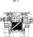
- FIG. 2 is a front view of the trolley type dump truck.
- FIG. 1 shows a use state in which a pantograph which is a current collecting device stands up
- FIG. 2 shows a storage state in which the pantograph is folded.
- an overhead wire 1 is extended from a feeding facility to a traveling road surface such as a large scale mine at a mining site, and a trolley type dump truck (hereinafter abbreviated as dump truck) 2 is used for ore transportation.
- dump truck trolley type dump truck
- the dump truck 2 is of an electric drive system that travels in combination with a trolley mode that travels with an electric power obtained from the overhead wire 1 and a diesel mode (non-trolley mode) that travels with an electric power obtained by driving a generator with a diesel engine ENG (refer to FIG. 8 ).
- the controller 40 includes a CPU, a ROM, a RAM, a communication I/F, and the like, and controls the traveling of the dump truck 2 by the CPU reading and executing a program stored in the ROM. Further, in addition to controlling an ascending and descending operation of the pantograph 3, the controller 40 controls the operation of a lock mechanism 35 by switching the excitation and non-excitation of an electromagnet 24a-1 incorporated in a hook device 24 to be described later.
- the trolley mode and the diesel mode are always used selectively for traveling.
- a climbing speed can be improved by traveling in the trolley mode using the electric power obtained from the overhead wire 1.
- the trolley mode and the diesel mode can be changed by operating a mode switch 41 (refer to FIG. 8 ).
- an AC drive system is employed in which when the dump truck 2 travels by driving the generator with the diesel engine, after electricity obtained in the generator has been controlled by a control equipment such as an inverter, an AC motor (induction motor) as a load device is driven to travel.
- a control equipment such as an inverter
- an AC motor induction motor
- IGBT Insulated Gate Bipolar Transistor
- a grid resistor if an IGBT (Insulated Gate Bipolar Transistor) inverter and a grid resistor are adopted, a higher electric braking force can be exerted.
- the pantograph 3 whose ascending and descending operation is controlled according to the controller 40 installed in the cab 7 is mounted on a front upper portion of the dump truck 2.
- a mount 5 for mounting the pantograph is installed on an upper portion of a pantograph support 4 provided on a deck 8 of the dump truck 2, and the pantograph 3 for collecting a current from the overhead wire 1 is installed on the mount 5.
- a collector shoe 6 as a current collecting portion which contacts with and slides on the overhead wire 1 and collects an electric power from the overhead wire 1 is installed on an upper portion of the pantograph 3.
- Reference numerals 9 and 9 'are steps for a driver or the like to get into the cab 7, and 10 is a handrail.
- pantographs 3 which are respectively installed on the right and left pantograph supports 4 are installed on the dump truck 2.
- the collector shoes 6 of the left and right pantographs 3 are connected to each other by a pantograph connecting plate 11 having an insulating property.
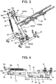
- FIG. 3 is an external perspective view of the pantograph 3 in a use state where the pantograph 3 stands up
- FIG. 4 is a side view showing a storage state in which the pantograph 3 is folded. The entire configuration of the pantograph 3 according to the present embodiment will be described with reference to FIGS. 3 and 4 .
- An underframe (base frame) 12 of the pantograph 3 is attached to the mount 5 on an upper portion of the pantograph support 4 described above.
- a base end of the lower frame (lower arm) 14 of the pantograph 3 is pivotably attached to an upper portion of the underframe 12 through a swing support shaft 13, and the lower frame 14 is configured to be able to rise and fall around the swing support shaft 13 which supports the base end.
- a connecting shaft 15 is provided parallel to the swing support shaft 13 at a leading end of the lower frame 14, and the base end of the upper frame (upper arm) 16 is pivotably linked to the connecting shaft 15.
- the collector shoe 6 is pivotably supported to a leading end of the upper end side of the upper frame 16 through a shoe support 28 and the like.
- the underframe 12, the lower frame 14 which is pivotably linked to the underframe 12, and the upper frame 16 that is pivotably linked to the lower frame 14 and supports the collector shoe 6 configure the framework 33.
- a lower balancing rod 17 is provided to form a parallel link mechanism with the lower frame 14, and an upper balancing rod 18 is provided to form a parallel link mechanism with the upper frame 16.
- the lower balancing rod 17 has a base end rotatably attached to the underframe 12.
- a parallel link receiver 19 is rotatably attached to the connecting shaft 15 provided at the leading end of the lower frame 14, and the leading end of the lower balancing rod 17 is rotatably connected to the parallel link receiver 19.
- the lower frame 14, the lower balancing rod 17, the underframe 12, and the parallel link receiver 19 configure a parallel link mechanism, and the parallel link receiver 19 is always kept in the same posture even when the lower frame 14 rises and falls.
- a base end of the upper balancing rod 18 is rotatably connected to the parallel link receiver 19 and a leading end of the upper balancing rod 18 is rotatably connected to a bracket 29 provided on the shoe support 28 of the collector shoe 6.
- a parallel link mechanism is configured by the upper frame 16, the upper balancing rod 18, the parallel link receiver 19, and the collector shoe 6, and the collector shoe 6 is always held at a horizontal position in the same posture even if the lower frame 14 and the upper frame 16 rise and fall.
- the collector shoe 6 can bring an upper surface of the collector shoe 6 in uniform contact with the overhead wire 1.
- the pantograph 3 when the hydraulic cylinder 20 is expanded and contracted, the pantograph 3 can be displaced between a standing posture (use state) in which the framework 33 stands up and the collector shoe 6 rises up to a position where the collector shoe 6 comes in contact with the overhead wire 1, and a folded posture (storage state) in which the framework 33 is folded and the collector shoe 6 descends.
- the collector shoe 6 can be pressed against the overhead wire 1 with a constant force through the lower frame 14 and the upper frame 16 by the spring force of the spring 21, and can move up and down by following a change in the height of an amplitude of the overhead wire 1.
- a leading end of the schematically illustrated damper device whose base end side is fixed to the underframe 12 is attached to a damper engagement portion 16e of a damper bracket 16d integrally attached to the arm 16a.
- the damper device suppresses the vibration of the upper frame 16.
- a shoe support 22 for supporting the collector shoe 6 can be provided at two positions in a longitudinal direction of the collector shoe 6 on the underframe 12 so as to be able to support both sides of the lower surface of the collector shoe 6.
- a cushioning material 23 made of an elastic material such as rubber is installed in the vicinity of a front center of the underframe 12.
- the cushioning material 23 abuts against the vicinity of an intermediate portion between the swing support shaft 13 and the connecting shaft 15 on the lower frame 14 to absorb or reduce the vibration acting on the lower frame 14.
- the cushioning material 23 is configured to cushion an impact caused by the contact with the local portion of the framework 33 at the time of folding the framework 33.
- the cushioning material 23 is installed between the underframe 12 and the lower frame 14 and plays a role of supporting the lower frame 14 and reducing the vibration of the framework 33 when the framework 33 is folded.
- the pantograph 3 is provided with a lock mechanism 35 for holding the framework 33 in the folded posture.
- the lock mechanism 35 includes an adsorption plate 27 (to be described in detail later) made of a magnetic material provided at the leading end of the upper frame 16, and an electromagnetic lock type hook device 24 for suctioning and holding the adsorption plate 27 by a magnetic force to restrict the movement of the upper frame 16 in the vertical direction at the time of folding the framework 33, and holding the framework 33 in a folded posture (fixing the upper frame 16 to the underframe 12) (refer to FIG. 3 ).
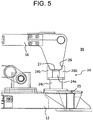
- FIG. 5 is a partially enlarged side view showing the hook device 24 provided in the pantograph 3 in a locked state.
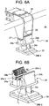
- FIGS. 6A and 6B are partially enlarged perspective views showing the hook device 24, in which FIG. 6A is a view showing a locked state of the hook device 24, and FIG. 6B is a view showing an unlocked state of the hook device 24.
- FIG. 6B illustrations of the upper frame 16 and so on are omitted.
- FIG. 7 is a perspective view showing the lower surface of the leading end of the upper frame 16 of the pantograph 3.
- an absorption plate (strike plate) 27 made of a magnetic material is attached to a fixing member 26 provided at the leading end of the upper frame 16.
- the fixing member 26 is made of, for example, a metal plate having a U-shaped cross section.
- the hook device 24 is provided with a hook portion 24a with a built-in electromagnet 24a-1, and a hook receiver 24b in which the fixing member 26 is seated, and which firmly receives the fixing member 26 in the vertical direction.
- a term "firmly” means that the fixing member 26 does not rattle against violent vibration or shaking when the dump truck 2 travels in the diesel mode with the pantograph 3 folded.
- the hook receiver 24b is made of a resin material having the strength necessary to firmly receive the fixing member 26, the material is not limited.
- the hook device 24 includes a bracket 24c for attaching the hook portion 24a and the hook receiver 24b, and an installation base 25 for mounting the bracket 24c to the underframe 12.
- the hook receiver 24b has a shape corresponding to the shape of the fixing member 26 having a substantially U-shaped cross section, and has a structure in which the fixing member 26 is just fitted into the hook receiver 24b when the framework 33 is folded.
- the hook receiver 24b has a structure in which the fixing member 26 and the hook receiver 24b are engaged with each other in a recession and projection fitting manner.
- a rubber plate 30 as an elastic material is attached to an abutment surface 24b-1 of the hook receiver 24b with the fixing member 26.
- the rubber plate 30 has a displacement prevention, an impact prevention, and a breakage prevention against the hook receiver 24b of the fixing member 26.
- the electromagnet 24a-1 incorporated in the hook device 24 is excited according to a pantograph descent command from the controller 40, and the electromagnet 24a-1 is not excited according to a pantograph ascent command.
- the electromagnet 24a-1 becomes excited or non-excited in conjunction with the ascending and descending operation of the pantograph 3.
- the ascent command and the descent command of the pantograph 3 is output, for example, by the operation of an operation button (not shown) in the cab 7.
- the pantograph 3 When the pantograph descent command is output, the pantograph 3 is gradually folded, and the adsorption plate 27 attached to the leading end of the upper frame 16 of the pantograph 3 is magnetically attracted by the electromagnet 24a-1, and the upper frame 16 is firmly fixed to the underframe 12 by the hook device 24. As a result, the framework 33 is always held in the folded posture without rattling the upper frame 16 in the vertical direction even in the case of severe vibration or shaking.
- the vibration of the framework 33 in the horizontal direction (the front-rear direction of the dump truck 2) can be also reduced.
- the pantograph 3 can be surely prevented from violently vibrating, or prevented from being damaged or deformed by large vibration.
- the electromagnet 24a-1 is adopted for the lock mechanism 35, and there is no movable portion such as a hook. For that reason, the possibility of breakage of the lock mechanism 35 is extremely low. In other words, according to the present embodiment, a life of the lock mechanism 35 can be extended.
- the controller 40 can issue a command for ascending and descending the pantograph 3 and a command (a command for excitation and non-excitation) for opening and closing the hook at the hook portion 24a at the same time, there are also advantages that a response to locking and unlocking of the lock mechanism 35 is excellent and a complicated control is not required.
- a proximity switch (posture detector) 31 can be provided for detecting whether the pantograph 3 is in a state of being completely descended and stored, or not (that is, a posture in which the framework 33 is folded) as shown in FIGS. 6A and FIG. 6B .
- the proximity switch 31 is attached, for example, in the vicinity of the hook portion 24a of the hook device 24, and is configured to be turned on/off depending on a position at which the adsorption plate 27 of the fixing member 26 approaches or separates from each other. Then, when the proximity switch 31 detects the folding posture of the framework 33, the controller 40 excites the electromagnet 24a-1 built in the hook portion 24a under control.
- the electromagnet 24a-1 can be excited at the timing when the framework 33 is folded, so that foreign matter such as iron scraps can be prevented from adhering to the electromagnet 24a-1, and the engaged state of the fixing member 26 and the hook receiver 24b can be maintained excellently.
- a sensor having a mechanical contact such as a limit switch or an optical sensor such as a photosensor can be employed instead of the proximity switch 31.
- the electric power used to excite the electromagnet 24a-1 may be supplied from a battery or the like, or may be supplied from a generator.
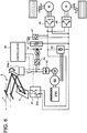
- FIG. 8 is a schematic diagram showing a power supply circuit for supplying an electric power to the electromagnet 24a-1 provided in the hook device 24 for fixing the pantograph 3 described above, with the inclusion of a peripheral configuration of the power supply circuit.
- the power supply circuit includes, as a generator used for the AC driven dump truck 2, a main generator G1 for supplying an electric power to a drive motor M for driving wheels, and a sub-generator G2 for supplying an electric power to an auxiliary equipment (electrical components) such as a cooling fan 44 and the like.
- the main generator G1 driven by the diesel engine ENG generally generates and outputs three-phase AC power. The generated electric power is converted into a DC power by a rectifier 43.
- the DC power is converted into an AC power of variable frequency by the inverters 45 and 46 and supplied to the drive motor M.
- the drive motor M is driven by the inverters 45 and 46 to rotate the wheels through a reduction gear.
- a chopper 47 and a regeneration resistor 48 are connected between the rectifier 43 and the inverters 45 and 46.
- the mode switch 41 includes a switch 41a that connects a received electric power from the overhead wire 1 to an internal circuit of the power supply circuit, and other control circuits.
- the mode switch 41 performs the switching operation based on a command of the controller 40, so that the power supply source is selected from the electric power from the overhead wire 1 (trolley power) and the electric power (generator power) from the main generator G1.
- the controller 40 is configured by a CPU that performs various calculations, a storage device such as a ROM or an HDD that stores programs for executing calculations by the CPU, a RAM that serves as a work area when the CPU executes the programs, hardware including a communication interface which is an interface for transmitting and receiving data with respect to other devices, and software stored in the storage device and executed by the CPU.
- a CPU that performs various calculations
- a storage device such as a ROM or an HDD that stores programs for executing calculations by the CPU
- a RAM that serves as a work area when the CPU executes the programs
- hardware including a communication interface which is an interface for transmitting and receiving data with respect to other devices, and software stored in the storage device and executed by the CPU.
- the mode switching command to the controller 40 may be issued by the driver of the dump truck 2, the overhead wire 1 may be recognized by a camera or the controller 40 may make a determination based on position information.
- the inverters 45, 46 for the drive motor M can receive a power supply by either the trolley power or the generator power selected by the mode switch 41.
- the sub-generator G2 supplies an electric power to the accessories including the electromagnet 24a-1 and the cooling fan 44.
- the electromagnet 24a-1 is supplied with a DC power through a rectifier 42.
- An AC power is supplied to a cooling fan motor MF that drives the cooling fan 44 through yet another inverter 49.
- the diesel engine ENG drives the sub-generator G2 set to an idling rotational speed by the controller 40 not only in the diesel mode but also in the trolley mode to drive to supply the electric power to the auxiliary devices regardless of the mode. Further, the controller 40 selects excitation or non-excitation of the electromagnet 24a-1 based on the power supply mode.
- the excitation can be made in the diesel mode and the non-excitation can be made in the trolley mode.
- an excitation state corresponding to a situation requiring the fixation of the pantograph 3 can be obtained in conjunction with switching of the mode.
- the operation of excitation in the diesel mode and the operation of non-excitation in the trolley mode can be interlocked with the mode switching, it is not bothersome to individually operate the excitation operation of the electromagnet 24a-1.
Landscapes
- Engineering & Computer Science (AREA)
- Transportation (AREA)
- Mechanical Engineering (AREA)
- Chemical & Material Sciences (AREA)
- Combustion & Propulsion (AREA)
- Power Engineering (AREA)
- Life Sciences & Earth Sciences (AREA)
- Sustainable Development (AREA)
- Sustainable Energy (AREA)
- Current-Collector Devices For Electrically Propelled Vehicles (AREA)
- Electric Propulsion And Braking For Vehicles (AREA)
- Hybrid Electric Vehicles (AREA)
- Arrangement Or Mounting Of Propulsion Units For Vehicles (AREA)
Abstract
Description
- The present invention relates to an electric drive vehicle that is used, for example, for ore transportation at a mining site such as a large scale mine, and travels by receiving an electric power from an overhead wire of a feeding facility through a current collecting device.
- Conventionally, when an electric drive vehicle is allowed to travel efficiently by an electric drive at a mining site where an overhead wire is installed from a feeding facility, there is a need to drive the electric drive vehicle so that a current collecting portion (also called a collector shoe or a slider) of a current collecting device provided so as to be able to move up and down does not come off the overhead line. The overhead wire is also called "trolley wire" and the current collecting device is also called "pantograph".
- A trolley type dump truck which is an example of an electric drive vehicle used in a mine or the like can travel with the use of two traveling modes including a trolley mode which travels with an electric power obtained from the overhead wire and a diesel mode (non-trolley mode) which travels with a diesel engine as a prime mover without obtaining an electric power from the overhead wire. The pantograph has a mechanism capable of controlling an ascent and a descent of the current collecting portion by the aid of a controller installed in a cab. When the trolley type dump truck travels in the trolley mode, the current collecting portion of the pantograph is raised to bring the overhead wire into contact with the current collecting portion to receive the electric power from the overhead wire. In addition, in a place where the overhead wire is not laid, the trolley type dump truck folds the pantograph, switches the traveling mode to the diesel mode, and generates the electric power by a generator driven by the diesel engine to travel.
- By the way, in general, a load surface of a place in which the overhead wire is not laid such as a loading site or a dumping site is not well maintained in a flat state as compared with a road surface in which the overhead wire is laid. For that reason, during traveling at a place where the overhead wire is not laid, the folded pantograph is subjected to a commeasurable vibration due to vibration. In other words, when traveling with the pantograph folded, the trolley type dump truck receives a large vibration due to the unevenness of the road surface or the like, and the pantograph mounted on the trolley type dump truck also vibrates greatly.
- For example,
Patent Literature 1 discloses a well-known technique related to the vibration countermeasure received at the time of folding the pantograph described above.Patent Literature 1 discloses that "there are provided a framework having a lower frame which is pivotably linked to an underframe and an upper frame which is pivotably linked to the lower frame and supports the collector shoe, and a lock mechanism that holds the framework in a folded posture. The lock mechanism includes a pivotable hook member having a hook portion engaged with a hook receiver provided on the collector shoe, a coil spring which urges the hook member toward one direction of pivoting directions in which the hook portion can be engaged with the hook receiver, and an actuator having a pressing rod portion that can be abutted against the hook member (refer to abstract). - PATENT LITERATURE 1: Japanese Patent Application Laid-Open Publication No.
2015-12744 -
Patent Literature 1 assumes a pantograph for railway vehicles, and since a traveling road surface is flat, there is no particular problem even if the look member of the lock mechanism is a pivotable movable portion. However, when the configuration ofPatent Literature 1 is applied to the trolley type dump truck as it is, the lock mechanism may be damaged due to vibration if the road surface is large in unevenness when traveling in the diesel mode at the time of feeding no electric power. For that reason, in order to apply the technique ofPatent Literature 1 to the trolley type dump truck, some improvement is required. - The present invention has been made in view of such a situation, and a technical problem of the present invention is to provide an electric drive vehicle capable of preventing a lock mechanism of a current collecting device from being damaged.
- In order to solve the above technical problems, according to one aspect of the present invention, there is provided an electric drive vehicle provided with a current collecting device installed at an upper portion of a vehicle body and receiving an electric power from an overhead wire. The current collecting device includes: a framework having an underframe, a lower frame that is pivotably linked to the underframe, and an upper frame that is pivotably linked to the lower frame; a current collecting portion that is supported by the upper frame; and a lock mechanism that holds the framework in a predetermined posture. The framework is capable of moving up and down between a standing posture in which the current collecting portion is ascended and a folded posture in which the current collecting portion is descended, and the lock mechanism includes an adsorption plate made of a magnetic material provided in the upper frame, and a hook device which is equipped with an electromagnet by a magnetic force to hold the framework in the folded posture as the predetermined posture.
- According to the present invention, since there is no movable part in the lock mechanism, the lock mechanism of the current collecting device can be prevented from being damaged. Other problems, configurations, and effects are clarified by the following description of the embodiment.
-
- [
FIG. 1] FIG. 1 is a side view of a trolley type dump truck according to an embodiment of the present invention. - [
FIG. 2] FIG. 2 is a front view of the trolley type dump truck ofFIG. 1 . - [
FIG. 3] FIG. 3 is a perspective view showing a pantograph shown inFIG. 1 in a standing posture. - [
FIG. 4] FIG. 4 is a side view showing the pantograph shown inFIG. 3 in a folded position. - [
FIG. 5] FIG. 5 is a partially enlarged side view showing a hook device shown inFIG. 3 in a locked state. - [
FIG. 6A] FIG. 6A is a partially enlarged perspective view showing the hook device shown inFIG. 5 , which shows a locked state of the hook device. - [
FIG. 6B] FIG. 6B is a partially enlarged perspective view showing the hook device shown inFIG. 5 , which shows an unlocked state of the hook device. - [
FIG. 7] FIG. 7 is a perspective view showing a lower surface of a leading end of an upper frame of the pantograph shown inFIG. 3 . - [
FIG. 8] FIG. 8 is a schematic view showing a power supply circuit for supplying an electric power to an electromagnet provided in the hook device for fixing the pantograph shown inFIG. 3 with the inclusion of a peripheral configuration of the power supply circuit. - Hereinafter, an electric drive vehicle according to the present invention will be described in detail with reference to the accompanying drawings.
-
FIG. 1 is a side view of a trolley type dump truck of an electric drive vehicle according to an embodiment of the present invention, andFIG. 2 is a front view of the trolley type dump truck.FIG. 1 shows a use state in which a pantograph which is a current collecting device stands up, andFIG. 2 shows a storage state in which the pantograph is folded. InFIG. 1 , anoverhead wire 1 is extended from a feeding facility to a traveling road surface such as a large scale mine at a mining site, and a trolley type dump truck (hereinafter abbreviated as dump truck) 2 is used for ore transportation. Thedump truck 2 is of an electric drive system that travels in combination with a trolley mode that travels with an electric power obtained from theoverhead wire 1 and a diesel mode (non-trolley mode) that travels with an electric power obtained by driving a generator with a diesel engine ENG (refer toFIG. 8 ). - Switching between the trolley mode and the diesel mode is performed by a
controller 40 provided in acab 7. Although not shown, thecontroller 40 includes a CPU, a ROM, a RAM, a communication I/F, and the like, and controls the traveling of thedump truck 2 by the CPU reading and executing a program stored in the ROM. Further, in addition to controlling an ascending and descending operation of thepantograph 3, thecontroller 40 controls the operation of alock mechanism 35 by switching the excitation and non-excitation of anelectromagnet 24a-1 incorporated in ahook device 24 to be described later. - In the present embodiment, the trolley mode and the diesel mode are always used selectively for traveling. In particular, at the time of climbing a hill, a climbing speed can be improved by traveling in the trolley mode using the electric power obtained from the
overhead wire 1. The trolley mode and the diesel mode can be changed by operating a mode switch 41 (refer toFIG. 8 ). - Further, an AC drive system is employed in which when the
dump truck 2 travels by driving the generator with the diesel engine, after electricity obtained in the generator has been controlled by a control equipment such as an inverter, an AC motor (induction motor) as a load device is driven to travel. Incidentally, if an IGBT (Insulated Gate Bipolar Transistor) inverter and a grid resistor are adopted, a higher electric braking force can be exerted. Thepantograph 3 whose ascending and descending operation is controlled according to thecontroller 40 installed in thecab 7 is mounted on a front upper portion of thedump truck 2. - Specifically, a
mount 5 for mounting the pantograph is installed on an upper portion of apantograph support 4 provided on adeck 8 of thedump truck 2, and thepantograph 3 for collecting a current from theoverhead wire 1 is installed on themount 5. Acollector shoe 6 as a current collecting portion which contacts with and slides on theoverhead wire 1 and collects an electric power from theoverhead wire 1 is installed on an upper portion of thepantograph 3.Reference numerals 9 and 9 'are steps for a driver or the like to get into thecab - Furthermore, referring to a front view of
FIG. 2 , twopantographs 3 which are respectively installed on the right andleft pantograph supports 4 are installed on thedump truck 2. Thecollector shoes 6 of the left andright pantographs 3 are connected to each other by apantograph connecting plate 11 having an insulating property. -
FIG. 3 is an external perspective view of thepantograph 3 in a use state where thepantograph 3 stands up, andFIG. 4 is a side view showing a storage state in which thepantograph 3 is folded. The entire configuration of thepantograph 3 according to the present embodiment will be described with reference toFIGS. 3 and 4 . - An underframe (base frame) 12 of the
pantograph 3 is attached to themount 5 on an upper portion of thepantograph support 4 described above. A base end of the lower frame (lower arm) 14 of thepantograph 3 is pivotably attached to an upper portion of theunderframe 12 through aswing support shaft 13, and thelower frame 14 is configured to be able to rise and fall around theswing support shaft 13 which supports the base end. A connectingshaft 15 is provided parallel to theswing support shaft 13 at a leading end of thelower frame 14, and the base end of the upper frame (upper arm) 16 is pivotably linked to the connectingshaft 15. Thecollector shoe 6 is pivotably supported to a leading end of the upper end side of theupper frame 16 through ashoe support 28 and the like. Theunderframe 12, thelower frame 14 which is pivotably linked to theunderframe 12, and theupper frame 16 that is pivotably linked to thelower frame 14 and supports thecollector shoe 6 configure theframework 33. - In the
pantograph 3, alower balancing rod 17 is provided to form a parallel link mechanism with thelower frame 14, and anupper balancing rod 18 is provided to form a parallel link mechanism with theupper frame 16. Thelower balancing rod 17 has a base end rotatably attached to theunderframe 12. Aparallel link receiver 19 is rotatably attached to the connectingshaft 15 provided at the leading end of thelower frame 14, and the leading end of thelower balancing rod 17 is rotatably connected to theparallel link receiver 19. In this example, thelower frame 14, thelower balancing rod 17, theunderframe 12, and theparallel link receiver 19 configure a parallel link mechanism, and theparallel link receiver 19 is always kept in the same posture even when thelower frame 14 rises and falls. - A base end of the
upper balancing rod 18 is rotatably connected to theparallel link receiver 19 and a leading end of theupper balancing rod 18 is rotatably connected to abracket 29 provided on theshoe support 28 of thecollector shoe 6. In this example, a parallel link mechanism is configured by theupper frame 16, theupper balancing rod 18, theparallel link receiver 19, and thecollector shoe 6, and thecollector shoe 6 is always held at a horizontal position in the same posture even if thelower frame 14 and theupper frame 16 rise and fall. As a result, even if thepantograph 3 ascends or descends, since thepantograph 3 is always held at a horizontal position in the same posture, thecollector shoe 6 can bring an upper surface of thecollector shoe 6 in uniform contact with theoverhead wire 1. - Furthermore, in the
pantograph 3, when the base end side is attached to theunderframe 12 and a hydraulic cylinder (actuator) 20 whose leading end side is connected to thelower frame 14 is extended, thelower frame 14 stands up. When thehydraulic cylinder 20 is contracted, thelower frame 14 falls downward. One end side (lower side inFIG. 3 ) of aspring 21 for raising theupper frame 16 is coupled to theunderframe 12. The other end side (upper side inFIG. 3 ) of thespring 21 is pivotably linked to anarm 16a provided so as to extend from the base end of theupper frame 16 to the opposite side of thecollector shoe 6 across the connectingshaft 15, through aspring bearing rod 16b and aspring bearing bracket 16c. - With the configuration described above, when the
hydraulic cylinder 20 is expanded and contracted, thepantograph 3 can be displaced between a standing posture (use state) in which theframework 33 stands up and thecollector shoe 6 rises up to a position where thecollector shoe 6 comes in contact with theoverhead wire 1, and a folded posture (storage state) in which theframework 33 is folded and thecollector shoe 6 descends. In addition, thecollector shoe 6 can be pressed against theoverhead wire 1 with a constant force through thelower frame 14 and theupper frame 16 by the spring force of thespring 21, and can move up and down by following a change in the height of an amplitude of theoverhead wire 1. A leading end of the schematically illustrated damper device whose base end side is fixed to theunderframe 12 is attached to adamper engagement portion 16e of adamper bracket 16d integrally attached to thearm 16a. The damper device suppresses the vibration of theupper frame 16. - In a state in which the
pantograph 3 is folded, ashoe support 22 for supporting thecollector shoe 6 can be provided at two positions in a longitudinal direction of thecollector shoe 6 on theunderframe 12 so as to be able to support both sides of the lower surface of thecollector shoe 6. In addition, in order to support a lower surface of thelower frame 14, acushioning material 23 made of an elastic material such as rubber is installed in the vicinity of a front center of theunderframe 12. The cushioningmaterial 23 abuts against the vicinity of an intermediate portion between theswing support shaft 13 and the connectingshaft 15 on thelower frame 14 to absorb or reduce the vibration acting on thelower frame 14. In other words, the cushioningmaterial 23 is configured to cushion an impact caused by the contact with the local portion of theframework 33 at the time of folding theframework 33. The cushioningmaterial 23 is installed between theunderframe 12 and thelower frame 14 and plays a role of supporting thelower frame 14 and reducing the vibration of theframework 33 when theframework 33 is folded. - In addition, the
pantograph 3 is provided with alock mechanism 35 for holding theframework 33 in the folded posture. Thelock mechanism 35 includes an adsorption plate 27 (to be described in detail later) made of a magnetic material provided at the leading end of theupper frame 16, and an electromagnetic locktype hook device 24 for suctioning and holding theadsorption plate 27 by a magnetic force to restrict the movement of theupper frame 16 in the vertical direction at the time of folding theframework 33, and holding theframework 33 in a folded posture (fixing theupper frame 16 to the underframe 12) (refer toFIG. 3 ). -
FIG. 5 is a partially enlarged side view showing thehook device 24 provided in thepantograph 3 in a locked state.FIGS. 6A and 6B are partially enlarged perspective views showing thehook device 24, in whichFIG. 6A is a view showing a locked state of thehook device 24, andFIG. 6B is a view showing an unlocked state of thehook device 24. Incidentally, inFIG. 6B , illustrations of theupper frame 16 and so on are omitted.FIG. 7 is a perspective view showing the lower surface of the leading end of theupper frame 16 of thepantograph 3. - Referring to
FIG. 7 , an absorption plate (strike plate) 27 made of a magnetic material is attached to a fixingmember 26 provided at the leading end of theupper frame 16. The fixingmember 26 is made of, for example, a metal plate having a U-shaped cross section. As shown inFIGS. 6A and 6B , thehook device 24 is provided with ahook portion 24a with a built-inelectromagnet 24a-1, and ahook receiver 24b in which the fixingmember 26 is seated, and which firmly receives the fixingmember 26 in the vertical direction. In the present specification, a term "firmly" means that the fixingmember 26 does not rattle against violent vibration or shaking when thedump truck 2 travels in the diesel mode with thepantograph 3 folded. For that reason, although thehook receiver 24b is made of a resin material having the strength necessary to firmly receive the fixingmember 26, the material is not limited. In addition, thehook device 24 includes abracket 24c for attaching thehook portion 24a and thehook receiver 24b, and aninstallation base 25 for mounting thebracket 24c to theunderframe 12. - The
hook receiver 24b has a shape corresponding to the shape of the fixingmember 26 having a substantially U-shaped cross section, and has a structure in which the fixingmember 26 is just fitted into thehook receiver 24b when theframework 33 is folded. In other words, thehook receiver 24b has a structure in which the fixingmember 26 and thehook receiver 24b are engaged with each other in a recession and projection fitting manner. Further, arubber plate 30 as an elastic material is attached to anabutment surface 24b-1 of thehook receiver 24b with the fixingmember 26. Therubber plate 30 has a displacement prevention, an impact prevention, and a breakage prevention against thehook receiver 24b of the fixingmember 26. - In the
pantograph 3 according to the present embodiment described above, theelectromagnet 24a-1 incorporated in thehook device 24 is excited according to a pantograph descent command from thecontroller 40, and theelectromagnet 24a-1 is not excited according to a pantograph ascent command. In other words, theelectromagnet 24a-1 becomes excited or non-excited in conjunction with the ascending and descending operation of thepantograph 3. The ascent command and the descent command of thepantograph 3 is output, for example, by the operation of an operation button (not shown) in thecab 7. - When the pantograph descent command is output, the
pantograph 3 is gradually folded, and theadsorption plate 27 attached to the leading end of theupper frame 16 of thepantograph 3 is magnetically attracted by theelectromagnet 24a-1, and theupper frame 16 is firmly fixed to theunderframe 12 by thehook device 24. As a result, theframework 33 is always held in the folded posture without rattling theupper frame 16 in the vertical direction even in the case of severe vibration or shaking. - Moreover, since the fixing
member 26 and thehook receiver 24b are engaged with each other in the recession and projection fitting manner, the vibration of theframework 33 in the horizontal direction (the front-rear direction of the dump truck 2) can be also reduced. As described above, according to the present embodiment, even when thedump trunk 2 travels on an uneven rough road surface in the diesel mode, thepantograph 3 can be surely prevented from violently vibrating, or prevented from being damaged or deformed by large vibration. Moreover, theelectromagnet 24a-1 is adopted for thelock mechanism 35, and there is no movable portion such as a hook. For that reason, the possibility of breakage of thelock mechanism 35 is extremely low. In other words, according to the present embodiment, a life of thelock mechanism 35 can be extended. - Further, in the electromagnetic lock
type hook device 24, since thecontroller 40 can issue a command for ascending and descending thepantograph 3 and a command (a command for excitation and non-excitation) for opening and closing the hook at thehook portion 24a at the same time, there are also advantages that a response to locking and unlocking of thelock mechanism 35 is excellent and a complicated control is not required. - In the present embodiment, a proximity switch (posture detector) 31 can be provided for detecting whether the
pantograph 3 is in a state of being completely descended and stored, or not (that is, a posture in which theframework 33 is folded) as shown inFIGS. 6A and FIG. 6B . The proximity switch 31 is attached, for example, in the vicinity of thehook portion 24a of thehook device 24, and is configured to be turned on/off depending on a position at which theadsorption plate 27 of the fixingmember 26 approaches or separates from each other. Then, when the proximity switch 31 detects the folding posture of theframework 33, thecontroller 40 excites theelectromagnet 24a-1 built in thehook portion 24a under control. In this way, theelectromagnet 24a-1 can be excited at the timing when theframework 33 is folded, so that foreign matter such as iron scraps can be prevented from adhering to theelectromagnet 24a-1, and the engaged state of the fixingmember 26 and thehook receiver 24b can be maintained excellently. - Incidentally, a sensor having a mechanical contact such as a limit switch or an optical sensor such as a photosensor can be employed instead of the proximity switch 31. The electric power used to excite the
electromagnet 24a-1 may be supplied from a battery or the like, or may be supplied from a generator. -
FIG. 8 is a schematic diagram showing a power supply circuit for supplying an electric power to theelectromagnet 24a-1 provided in thehook device 24 for fixing thepantograph 3 described above, with the inclusion of a peripheral configuration of the power supply circuit. The power supply circuit includes, as a generator used for the AC drivendump truck 2, a main generator G1 for supplying an electric power to a drive motor M for driving wheels, and a sub-generator G2 for supplying an electric power to an auxiliary equipment (electrical components) such as a coolingfan 44 and the like. The main generator G1 driven by the diesel engine ENG generally generates and outputs three-phase AC power. The generated electric power is converted into a DC power by arectifier 43. The DC power is converted into an AC power of variable frequency by theinverters inverters chopper 47 and aregeneration resistor 48 are connected between therectifier 43 and theinverters - Next, a power supply operation corresponding to mode switching in the power supply circuit will be described. The electric power from the
overhead wire 1 in the AC drivendump truck 2 is supplied to the drive motor M (load device) in a two-wire manner, unlike a general train. Themode switch 41 includes aswitch 41a that connects a received electric power from theoverhead wire 1 to an internal circuit of the power supply circuit, and other control circuits. Themode switch 41 performs the switching operation based on a command of thecontroller 40, so that the power supply source is selected from the electric power from the overhead wire 1 (trolley power) and the electric power (generator power) from the main generator G1. - Although not shown, the
controller 40 is configured by a CPU that performs various calculations, a storage device such as a ROM or an HDD that stores programs for executing calculations by the CPU, a RAM that serves as a work area when the CPU executes the programs, hardware including a communication interface which is an interface for transmitting and receiving data with respect to other devices, and software stored in the storage device and executed by the CPU. - Although the mode switching command to the
controller 40 may be issued by the driver of thedump truck 2, theoverhead wire 1 may be recognized by a camera or thecontroller 40 may make a determination based on position information. Theinverters mode switch 41. - On the other hand, the sub-generator G2 supplies an electric power to the accessories including the
electromagnet 24a-1 and the coolingfan 44. Theelectromagnet 24a-1 is supplied with a DC power through arectifier 42. An AC power is supplied to a cooling fan motor MF that drives the coolingfan 44 through yet anotherinverter 49. The diesel engine ENG drives the sub-generator G2 set to an idling rotational speed by thecontroller 40 not only in the diesel mode but also in the trolley mode to drive to supply the electric power to the auxiliary devices regardless of the mode. Further, thecontroller 40 selects excitation or non-excitation of theelectromagnet 24a-1 based on the power supply mode. - In this example, if switching of the power supply source for exciting the
electromagnet 24a-1 is interlocked with the mode switching, the excitation can be made in the diesel mode and the non-excitation can be made in the trolley mode. As a result, an excitation state corresponding to a situation requiring the fixation of thepantograph 3 can be obtained in conjunction with switching of the mode. As a result, since the operation of excitation in the diesel mode and the operation of non-excitation in the trolley mode can be interlocked with the mode switching, it is not bothersome to individually operate the excitation operation of theelectromagnet 24a-1. - The present invention is not limited to the embodiment described above, and various modifications can be made without departing from the technical spirit of the present invention, and all the technical matters included in the technical concept described in the claims are included in the subject of the present invention. The above-mentioned embodiment shows a preferable example, a person skilled in the art can realize various modifications from the disclosed contents, and those various modifications are included in the scope of the appended claims.
-
- 1: overhead wire
- 2: dump truck
- 3: pantograph
- 6: collector shoe (current collecting portion)
- 12: underframe
- 14: lower frame
- 16: upper frame
- 23: cushioning material
- 24: hook device
- 24a: hook portion
- 24a-1: electromagnet
- 24b: hook receiver
- 24b-1: abutment surface
- 26: fixing member
- 27: adsorption plate
- 30: rubber plate (elastic material)
- 31: limit switch (posture detector)
- 33: framework
- 35: lock device
- 40: controller
- 41: mode switch
- 41a: switch
- M: drive motor (load device)
Claims (7)
- An electric drive vehicle comprising a current collecting device installed at an upper portion of a vehicle body and receiving an electric power from an overhead wire,
wherein the current collecting device includes:a framework having an underframe, a lower frame that is pivotably linked to the underframe, and an upper frame that is pivotably linked to the lower frame;a current collecting portion that is supported by the upper frame; anda lock mechanism that holds the framework in a predetermined posture,the framework is capable of moving up and down between a standing posture in which the current collecting portion is ascended and a folded posture in which the current collecting portion is descended, and
the lock mechanism includes an adsorption plate made of a magnetic material provided in the upper frame, and a hook device which is equipped with an electromagnet and adsorbs to hold the adsorption plate by a magnetic force to hold the framework in the folded posture as the predetermined posture. - The electric drive vehicle according to claim 1, further comprising a controller that controls excitation and non-excitation of the electromagnet,
wherein the controller de-excites the electromagnet in conjunction with an ascending movement of the framework. - The electric drive vehicle according to claim 2, further comprising a posture detector that detects whether or not the framework is in the folded posture,
wherein the controller excites the electromagnet when the posture detector detects that the framework is in the folded postured. - The electric drive vehicle according to claim 1, further comprising: a prime mover; a generator driven by the prime mover; a power supply circuit that uses a generator power obtained by the generator, and a trolley power obtained by power received from the overhead wire as a drive power for a load device; and a controller that controls excitation and non-excitation of the electromagnet,
wherein the controller controls opening and closing of a switch provided in the power supply circuit, switches a power feeding mode to the load device from a diesel mode for feeding the generator power or a trolley mode for feeding the trolley power, and excites the electromagnet when the feeding mode is the diesel mode. - The electric drive vehicle according to claim 1,
wherein a fixing member for attaching the adsorption plate is provided at a leading end of the upper frame,
the hook device has a hook receiver that is abutted against the fixing member, and
the fixing member and the hook receiver are formed to be engaged with each other in a recession and projection fitting manner and regulate motion in a horizontal direction. - The electric drive vehicle according to claim 5, wherein an elastic material is provided on an abutment surface of the hook receiver against the fixing member.
- The electric drive vehicle according to claim 5, wherein the underframe is provided with a cushioning material for cushioning an impact caused by an abutment with a local portion of the framework when the framework is folded.
Applications Claiming Priority (2)
| Application Number | Priority Date | Filing Date | Title |
|---|---|---|---|
| JP2017178684A JP6695311B2 (en) | 2017-09-19 | 2017-09-19 | Electric drive vehicle |
| PCT/JP2018/028157 WO2019058757A1 (en) | 2017-09-19 | 2018-07-26 | Elecrrically powered vehicle |
Publications (3)
| Publication Number | Publication Date |
|---|---|
| EP3578408A1 true EP3578408A1 (en) | 2019-12-11 |
| EP3578408A4 EP3578408A4 (en) | 2021-01-13 |
| EP3578408B1 EP3578408B1 (en) | 2023-04-19 |
Family
ID=65810354
Family Applications (1)
| Application Number | Title | Priority Date | Filing Date |
|---|---|---|---|
| EP18857945.2A Active EP3578408B1 (en) | 2017-09-19 | 2018-07-26 | Electrically powered vehicle |
Country Status (5)
| Country | Link |
|---|---|
| US (1) | US10894468B2 (en) |
| EP (1) | EP3578408B1 (en) |
| JP (1) | JP6695311B2 (en) |
| CN (1) | CN110352142B (en) |
| WO (1) | WO2019058757A1 (en) |
Families Citing this family (8)
| Publication number | Priority date | Publication date | Assignee | Title |
|---|---|---|---|---|
| JP6495815B2 (en) * | 2015-12-28 | 2019-04-03 | 日立建機株式会社 | Electric drive dump truck |
| DE102016205012A1 (en) * | 2016-03-24 | 2017-09-28 | Schunk Bahn- Und Industrietechnik Gmbh | Positioning unit and method of contacting |
| CN107539192B (en) * | 2016-06-29 | 2019-08-13 | 比亚迪股份有限公司 | An electric mine dump truck |
| JP6695311B2 (en) * | 2017-09-19 | 2020-05-20 | 日立建機株式会社 | Electric drive vehicle |
| JP7338216B2 (en) * | 2019-04-12 | 2023-09-05 | 株式会社デンソー | contact receiving system, program |
| CN111114333A (en) * | 2020-01-03 | 2020-05-08 | 北京中车赛德铁道电气科技有限公司 | Multifunctional high-speed pantograph auxiliary pantograph lifting device |
| US12528359B2 (en) * | 2022-07-21 | 2026-01-20 | Caterpillar Inc. | Pantograph assembly with force dampeners |
| US12522078B2 (en) | 2022-11-10 | 2026-01-13 | Caterpillar Inc. | Deployable power rail connector for electric machine and method |
Family Cites Families (16)
| Publication number | Priority date | Publication date | Assignee | Title |
|---|---|---|---|---|
| US5954171A (en) * | 1996-08-05 | 1999-09-21 | Abb Patent Gmbh | Moving contact |
| FR2800680B1 (en) * | 1999-11-10 | 2003-01-17 | Alstom | CURRENT CAPTURE ASSEMBLY AND CORRESPONDING RAIL VEHICLE |
| FR2910391B1 (en) * | 2006-12-20 | 2013-11-29 | Lohr Ind | OCCASIONAL ELECTRIC ENERGY CAPTURING SYSTEM, IN PARTICULAR FOR AN URBAN PUBLIC TRANSPORT VEHICLE. |
| KR20120101566A (en) * | 2009-12-23 | 2012-09-13 | 프로테라 인크 | Charging stations for electric vehicles |
| JP5844452B2 (en) * | 2012-02-22 | 2016-01-20 | 株式会社日立パワーソリューションズ | Pantograph control device for trolley truck |
| US9393874B2 (en) * | 2012-02-22 | 2016-07-19 | Hitachi Power Solutions Co., Ltd. | Trolley-type truck |
| JP5932995B2 (en) * | 2012-05-31 | 2016-06-08 | 株式会社日立パワーソリューションズ | Pantograph device for trolley truck |
| US9381818B2 (en) * | 2012-09-28 | 2016-07-05 | Siemens Aktiengesellschaft | Non-track-bound vehicle |
| ITMI20130064A1 (en) * | 2013-01-18 | 2014-07-19 | Tesmec Spa | ILLUSTRATION PANTOGRAPH |
| US9988835B2 (en) * | 2013-06-20 | 2018-06-05 | Volvo Truck Corporation | Protection arrangement for an electric vehicle |
| JP2015012744A (en) | 2013-07-01 | 2015-01-19 | 東洋電機製造株式会社 | Pantograph for railway vehicle |
| WO2015075773A1 (en) * | 2013-11-19 | 2015-05-28 | 日立建機株式会社 | Trolley truck pantograph device |
| CN104890520B (en) * | 2015-06-16 | 2018-02-23 | 中车株洲电力机车有限公司 | A kind of lateral current collector and electric vehicle |
| DE102015215174A1 (en) * | 2015-08-07 | 2017-02-09 | Siemens Aktiengesellschaft | Device and a method for the overhead operation of a rail vehicle |
| US9796267B1 (en) * | 2016-06-03 | 2017-10-24 | Caterpillar Inc. | Machine operation assistance based on height detection of machine load using a camera |
| JP6695311B2 (en) * | 2017-09-19 | 2020-05-20 | 日立建機株式会社 | Electric drive vehicle |
-
2017
- 2017-09-19 JP JP2017178684A patent/JP6695311B2/en active Active
-
2018
- 2018-07-26 EP EP18857945.2A patent/EP3578408B1/en active Active
- 2018-07-26 US US16/490,993 patent/US10894468B2/en active Active
- 2018-07-26 WO PCT/JP2018/028157 patent/WO2019058757A1/en not_active Ceased
- 2018-07-26 CN CN201880014382.XA patent/CN110352142B/en active Active
Also Published As
| Publication number | Publication date |
|---|---|
| WO2019058757A1 (en) | 2019-03-28 |
| JP2019054679A (en) | 2019-04-04 |
| US10894468B2 (en) | 2021-01-19 |
| CN110352142A (en) | 2019-10-18 |
| US20200009955A1 (en) | 2020-01-09 |
| CN110352142B (en) | 2022-09-20 |
| EP3578408B1 (en) | 2023-04-19 |
| EP3578408A4 (en) | 2021-01-13 |
| JP6695311B2 (en) | 2020-05-20 |
Similar Documents
| Publication | Publication Date | Title |
|---|---|---|
| US10894468B2 (en) | Electric drive vehicle | |
| EP2857252B1 (en) | Pantograph device of trolley truck | |
| US9393874B2 (en) | Trolley-type truck | |
| US20120118653A1 (en) | In-vehicle electronic component disposing construction for electronic component for electric motor for driving vehicle | |
| CN101606308B (en) | Load drive device | |
| WO2015075773A1 (en) | Trolley truck pantograph device | |
| CN104228708A (en) | Opening and closing apparatus | |
| JP2019167060A (en) | Battery pack protection structure of vehicle | |
| JP5844452B2 (en) | Pantograph control device for trolley truck | |
| WO2008035768A1 (en) | Vehicle travel control system | |
| JP7127581B2 (en) | In-vehicle structure of electric parts | |
| KR102028798B1 (en) | Electric moter vehicle capable hybrid drive | |
| JP2000211430A (en) | Getting in/out step apparatus for vehicle | |
| US20080125926A1 (en) | Electric Vehicle Control Device | |
| CN216994521U (en) | Electromagnetic control-based tire puncture prevention device, system and automobile | |
| JP2013052711A (en) | Structure for mounting seatbelt retractor | |
| JPH11115797A (en) | Vehicle frame structure | |
| JPH08235992A (en) | Relay mounting structure | |
| CN209127833U (en) | A kind of carriage resilient cushion | |
| JP2007068263A (en) | Electric vehicle cable protection structure | |
| KR100482679B1 (en) | Automobile battery mounting structure | |
| JP2010241308A (en) | Vehicle control device | |
| JP2005081936A (en) | Electric motorbike for running on rail track | |
| JP2001169412A (en) | Car using linear motor | |
| JP2005119596A (en) | Battery fixing structure for driving auxiliary equipment |
Legal Events
| Date | Code | Title | Description |
|---|---|---|---|
| STAA | Information on the status of an ep patent application or granted ep patent |
Free format text: STATUS: THE INTERNATIONAL PUBLICATION HAS BEEN MADE |
|
| PUAI | Public reference made under article 153(3) epc to a published international application that has entered the european phase |
Free format text: ORIGINAL CODE: 0009012 |
|
| STAA | Information on the status of an ep patent application or granted ep patent |
Free format text: STATUS: REQUEST FOR EXAMINATION WAS MADE |
|
| 17P | Request for examination filed |
Effective date: 20190903 |
|
| AK | Designated contracting states |
Kind code of ref document: A1 Designated state(s): AL AT BE BG CH CY CZ DE DK EE ES FI FR GB GR HR HU IE IS IT LI LT LU LV MC MK MT NL NO PL PT RO RS SE SI SK SM TR |
|
| AX | Request for extension of the european patent |
Extension state: BA ME |
|
| DAV | Request for validation of the european patent (deleted) | ||
| DAX | Request for extension of the european patent (deleted) | ||
| A4 | Supplementary search report drawn up and despatched |
Effective date: 20201216 |
|
| RIC1 | Information provided on ipc code assigned before grant |
Ipc: B60K 6/46 20071001ALI20201210BHEP Ipc: B60L 50/10 20190101ALI20201210BHEP Ipc: B60K 1/00 20060101ALI20201210BHEP Ipc: B60L 5/26 20060101ALI20201210BHEP Ipc: B60L 9/18 20060101ALI20201210BHEP Ipc: B60K 6/22 20071001ALN20201210BHEP Ipc: B60L 5/24 20060101AFI20201210BHEP |
|
| RIC1 | Information provided on ipc code assigned before grant |
Ipc: B60K 6/22 20071001ALN20220831BHEP Ipc: B60L 50/10 20190101ALI20220831BHEP Ipc: B60L 9/18 20060101ALI20220831BHEP Ipc: B60L 5/26 20060101ALI20220831BHEP Ipc: B60K 6/46 20071001ALI20220831BHEP Ipc: B60K 1/00 20060101ALI20220831BHEP Ipc: B60L 5/24 20060101AFI20220831BHEP |
|
| GRAP | Despatch of communication of intention to grant a patent |
Free format text: ORIGINAL CODE: EPIDOSNIGR1 |
|
| STAA | Information on the status of an ep patent application or granted ep patent |
Free format text: STATUS: GRANT OF PATENT IS INTENDED |
|
| RIC1 | Information provided on ipc code assigned before grant |
Ipc: B60K 6/22 20071001ALN20220926BHEP Ipc: B60L 50/10 20190101ALI20220926BHEP Ipc: B60L 9/18 20060101ALI20220926BHEP Ipc: B60L 5/26 20060101ALI20220926BHEP Ipc: B60K 6/46 20071001ALI20220926BHEP Ipc: B60K 1/00 20060101ALI20220926BHEP Ipc: B60L 5/24 20060101AFI20220926BHEP |
|
| RIC1 | Information provided on ipc code assigned before grant |
Ipc: B60K 6/22 20071001ALN20221019BHEP Ipc: B60L 50/10 20190101ALI20221019BHEP Ipc: B60L 9/18 20060101ALI20221019BHEP Ipc: B60L 5/26 20060101ALI20221019BHEP Ipc: B60K 6/46 20071001ALI20221019BHEP Ipc: B60K 1/00 20060101ALI20221019BHEP Ipc: B60L 5/24 20060101AFI20221019BHEP |
|
| INTG | Intention to grant announced |
Effective date: 20221102 |
|
| GRAS | Grant fee paid |
Free format text: ORIGINAL CODE: EPIDOSNIGR3 |
|
| GRAA | (expected) grant |
Free format text: ORIGINAL CODE: 0009210 |
|
| STAA | Information on the status of an ep patent application or granted ep patent |
Free format text: STATUS: THE PATENT HAS BEEN GRANTED |
|
| AK | Designated contracting states |
Kind code of ref document: B1 Designated state(s): AL AT BE BG CH CY CZ DE DK EE ES FI FR GB GR HR HU IE IS IT LI LT LU LV MC MK MT NL NO PL PT RO RS SE SI SK SM TR |
|
| REG | Reference to a national code |
Ref country code: GB Ref legal event code: FG4D |
|
| REG | Reference to a national code |
Ref country code: DE Ref legal event code: R096 Ref document number: 602018048719 Country of ref document: DE |
|
| REG | Reference to a national code |
Ref country code: CH Ref legal event code: EP |
|
| REG | Reference to a national code |
Ref country code: IE Ref legal event code: FG4D |
|
| REG | Reference to a national code |
Ref country code: AT Ref legal event code: REF Ref document number: 1560952 Country of ref document: AT Kind code of ref document: T Effective date: 20230515 |
|
| REG | Reference to a national code |
Ref country code: LT Ref legal event code: MG9D |
|
| REG | Reference to a national code |
Ref country code: NL Ref legal event code: MP Effective date: 20230419 |
|
| REG | Reference to a national code |
Ref country code: AT Ref legal event code: MK05 Ref document number: 1560952 Country of ref document: AT Kind code of ref document: T Effective date: 20230419 |
|
| PG25 | Lapsed in a contracting state [announced via postgrant information from national office to epo] |
Ref country code: NL Free format text: LAPSE BECAUSE OF FAILURE TO SUBMIT A TRANSLATION OF THE DESCRIPTION OR TO PAY THE FEE WITHIN THE PRESCRIBED TIME-LIMIT Effective date: 20230419 |
|
| PG25 | Lapsed in a contracting state [announced via postgrant information from national office to epo] |
Ref country code: SE Free format text: LAPSE BECAUSE OF FAILURE TO SUBMIT A TRANSLATION OF THE DESCRIPTION OR TO PAY THE FEE WITHIN THE PRESCRIBED TIME-LIMIT Effective date: 20230419 Ref country code: PT Free format text: LAPSE BECAUSE OF FAILURE TO SUBMIT A TRANSLATION OF THE DESCRIPTION OR TO PAY THE FEE WITHIN THE PRESCRIBED TIME-LIMIT Effective date: 20230821 Ref country code: NO Free format text: LAPSE BECAUSE OF FAILURE TO SUBMIT A TRANSLATION OF THE DESCRIPTION OR TO PAY THE FEE WITHIN THE PRESCRIBED TIME-LIMIT Effective date: 20230719 Ref country code: ES Free format text: LAPSE BECAUSE OF FAILURE TO SUBMIT A TRANSLATION OF THE DESCRIPTION OR TO PAY THE FEE WITHIN THE PRESCRIBED TIME-LIMIT Effective date: 20230419 Ref country code: AT Free format text: LAPSE BECAUSE OF FAILURE TO SUBMIT A TRANSLATION OF THE DESCRIPTION OR TO PAY THE FEE WITHIN THE PRESCRIBED TIME-LIMIT Effective date: 20230419 |
|
| PG25 | Lapsed in a contracting state [announced via postgrant information from national office to epo] |
Ref country code: RS Free format text: LAPSE BECAUSE OF FAILURE TO SUBMIT A TRANSLATION OF THE DESCRIPTION OR TO PAY THE FEE WITHIN THE PRESCRIBED TIME-LIMIT Effective date: 20230419 Ref country code: PL Free format text: LAPSE BECAUSE OF FAILURE TO SUBMIT A TRANSLATION OF THE DESCRIPTION OR TO PAY THE FEE WITHIN THE PRESCRIBED TIME-LIMIT Effective date: 20230419 Ref country code: LV Free format text: LAPSE BECAUSE OF FAILURE TO SUBMIT A TRANSLATION OF THE DESCRIPTION OR TO PAY THE FEE WITHIN THE PRESCRIBED TIME-LIMIT Effective date: 20230419 Ref country code: LT Free format text: LAPSE BECAUSE OF FAILURE TO SUBMIT A TRANSLATION OF THE DESCRIPTION OR TO PAY THE FEE WITHIN THE PRESCRIBED TIME-LIMIT Effective date: 20230419 Ref country code: IS Free format text: LAPSE BECAUSE OF FAILURE TO SUBMIT A TRANSLATION OF THE DESCRIPTION OR TO PAY THE FEE WITHIN THE PRESCRIBED TIME-LIMIT Effective date: 20230819 Ref country code: HR Free format text: LAPSE BECAUSE OF FAILURE TO SUBMIT A TRANSLATION OF THE DESCRIPTION OR TO PAY THE FEE WITHIN THE PRESCRIBED TIME-LIMIT Effective date: 20230419 Ref country code: GR Free format text: LAPSE BECAUSE OF FAILURE TO SUBMIT A TRANSLATION OF THE DESCRIPTION OR TO PAY THE FEE WITHIN THE PRESCRIBED TIME-LIMIT Effective date: 20230720 Ref country code: AL Free format text: LAPSE BECAUSE OF FAILURE TO SUBMIT A TRANSLATION OF THE DESCRIPTION OR TO PAY THE FEE WITHIN THE PRESCRIBED TIME-LIMIT Effective date: 20230419 |
|
| PG25 | Lapsed in a contracting state [announced via postgrant information from national office to epo] |
Ref country code: FI Free format text: LAPSE BECAUSE OF FAILURE TO SUBMIT A TRANSLATION OF THE DESCRIPTION OR TO PAY THE FEE WITHIN THE PRESCRIBED TIME-LIMIT Effective date: 20230419 |
|
| PG25 | Lapsed in a contracting state [announced via postgrant information from national office to epo] |
Ref country code: SK Free format text: LAPSE BECAUSE OF FAILURE TO SUBMIT A TRANSLATION OF THE DESCRIPTION OR TO PAY THE FEE WITHIN THE PRESCRIBED TIME-LIMIT Effective date: 20230419 |
|
| REG | Reference to a national code |
Ref country code: DE Ref legal event code: R097 Ref document number: 602018048719 Country of ref document: DE |
|
| PG25 | Lapsed in a contracting state [announced via postgrant information from national office to epo] |
Ref country code: SM Free format text: LAPSE BECAUSE OF FAILURE TO SUBMIT A TRANSLATION OF THE DESCRIPTION OR TO PAY THE FEE WITHIN THE PRESCRIBED TIME-LIMIT Effective date: 20230419 Ref country code: SK Free format text: LAPSE BECAUSE OF FAILURE TO SUBMIT A TRANSLATION OF THE DESCRIPTION OR TO PAY THE FEE WITHIN THE PRESCRIBED TIME-LIMIT Effective date: 20230419 Ref country code: RO Free format text: LAPSE BECAUSE OF FAILURE TO SUBMIT A TRANSLATION OF THE DESCRIPTION OR TO PAY THE FEE WITHIN THE PRESCRIBED TIME-LIMIT Effective date: 20230419 Ref country code: EE Free format text: LAPSE BECAUSE OF FAILURE TO SUBMIT A TRANSLATION OF THE DESCRIPTION OR TO PAY THE FEE WITHIN THE PRESCRIBED TIME-LIMIT Effective date: 20230419 Ref country code: DK Free format text: LAPSE BECAUSE OF FAILURE TO SUBMIT A TRANSLATION OF THE DESCRIPTION OR TO PAY THE FEE WITHIN THE PRESCRIBED TIME-LIMIT Effective date: 20230419 Ref country code: CZ Free format text: LAPSE BECAUSE OF FAILURE TO SUBMIT A TRANSLATION OF THE DESCRIPTION OR TO PAY THE FEE WITHIN THE PRESCRIBED TIME-LIMIT Effective date: 20230419 |
|
| PLBE | No opposition filed within time limit |
Free format text: ORIGINAL CODE: 0009261 |
|
| STAA | Information on the status of an ep patent application or granted ep patent |
Free format text: STATUS: NO OPPOSITION FILED WITHIN TIME LIMIT |
|
| PG25 | Lapsed in a contracting state [announced via postgrant information from national office to epo] |
Ref country code: MC Free format text: LAPSE BECAUSE OF FAILURE TO SUBMIT A TRANSLATION OF THE DESCRIPTION OR TO PAY THE FEE WITHIN THE PRESCRIBED TIME-LIMIT Effective date: 20230419 |
|
| PG25 | Lapsed in a contracting state [announced via postgrant information from national office to epo] |
Ref country code: MC Free format text: LAPSE BECAUSE OF FAILURE TO SUBMIT A TRANSLATION OF THE DESCRIPTION OR TO PAY THE FEE WITHIN THE PRESCRIBED TIME-LIMIT Effective date: 20230419 |
|
| REG | Reference to a national code |
Ref country code: CH Ref legal event code: PL |
|
| REG | Reference to a national code |
Ref country code: BE Ref legal event code: MM Effective date: 20230731 |
|
| PG25 | Lapsed in a contracting state [announced via postgrant information from national office to epo] |
Ref country code: LU Free format text: LAPSE BECAUSE OF NON-PAYMENT OF DUE FEES Effective date: 20230726 |
|
| 26N | No opposition filed |
Effective date: 20240122 |
|
| GBPC | Gb: european patent ceased through non-payment of renewal fee |
Effective date: 20230726 |
|
| PG25 | Lapsed in a contracting state [announced via postgrant information from national office to epo] |
Ref country code: LU Free format text: LAPSE BECAUSE OF NON-PAYMENT OF DUE FEES Effective date: 20230726 |
|
| REG | Reference to a national code |
Ref country code: IE Ref legal event code: MM4A |
|
| PG25 | Lapsed in a contracting state [announced via postgrant information from national office to epo] |
Ref country code: CH Free format text: LAPSE BECAUSE OF NON-PAYMENT OF DUE FEES Effective date: 20230731 Ref country code: GB Free format text: LAPSE BECAUSE OF NON-PAYMENT OF DUE FEES Effective date: 20230726 |
|
| PG25 | Lapsed in a contracting state [announced via postgrant information from national office to epo] |
Ref country code: SI Free format text: LAPSE BECAUSE OF FAILURE TO SUBMIT A TRANSLATION OF THE DESCRIPTION OR TO PAY THE FEE WITHIN THE PRESCRIBED TIME-LIMIT Effective date: 20230419 |
|
| PG25 | Lapsed in a contracting state [announced via postgrant information from national office to epo] |
Ref country code: SI Free format text: LAPSE BECAUSE OF FAILURE TO SUBMIT A TRANSLATION OF THE DESCRIPTION OR TO PAY THE FEE WITHIN THE PRESCRIBED TIME-LIMIT Effective date: 20230419 Ref country code: IT Free format text: LAPSE BECAUSE OF FAILURE TO SUBMIT A TRANSLATION OF THE DESCRIPTION OR TO PAY THE FEE WITHIN THE PRESCRIBED TIME-LIMIT Effective date: 20230419 Ref country code: FR Free format text: LAPSE BECAUSE OF NON-PAYMENT OF DUE FEES Effective date: 20230731 Ref country code: BE Free format text: LAPSE BECAUSE OF NON-PAYMENT OF DUE FEES Effective date: 20230731 |
|
| PG25 | Lapsed in a contracting state [announced via postgrant information from national office to epo] |
Ref country code: IE Free format text: LAPSE BECAUSE OF NON-PAYMENT OF DUE FEES Effective date: 20230726 |
|
| PG25 | Lapsed in a contracting state [announced via postgrant information from national office to epo] |
Ref country code: IE Free format text: LAPSE BECAUSE OF NON-PAYMENT OF DUE FEES Effective date: 20230726 |
|
| PG25 | Lapsed in a contracting state [announced via postgrant information from national office to epo] |
Ref country code: BG Free format text: LAPSE BECAUSE OF FAILURE TO SUBMIT A TRANSLATION OF THE DESCRIPTION OR TO PAY THE FEE WITHIN THE PRESCRIBED TIME-LIMIT Effective date: 20230419 |
|
| PG25 | Lapsed in a contracting state [announced via postgrant information from national office to epo] |
Ref country code: BG Free format text: LAPSE BECAUSE OF FAILURE TO SUBMIT A TRANSLATION OF THE DESCRIPTION OR TO PAY THE FEE WITHIN THE PRESCRIBED TIME-LIMIT Effective date: 20230419 |
|
| PG25 | Lapsed in a contracting state [announced via postgrant information from national office to epo] |
Ref country code: CY Free format text: LAPSE BECAUSE OF FAILURE TO SUBMIT A TRANSLATION OF THE DESCRIPTION OR TO PAY THE FEE WITHIN THE PRESCRIBED TIME-LIMIT; INVALID AB INITIO Effective date: 20180726 |
|
| PG25 | Lapsed in a contracting state [announced via postgrant information from national office to epo] |
Ref country code: HU Free format text: LAPSE BECAUSE OF FAILURE TO SUBMIT A TRANSLATION OF THE DESCRIPTION OR TO PAY THE FEE WITHIN THE PRESCRIBED TIME-LIMIT; INVALID AB INITIO Effective date: 20180726 |
|
| PGFP | Annual fee paid to national office [announced via postgrant information from national office to epo] |
Ref country code: DE Payment date: 20250604 Year of fee payment: 8 |
|
| PG25 | Lapsed in a contracting state [announced via postgrant information from national office to epo] |
Ref country code: TR Free format text: LAPSE BECAUSE OF FAILURE TO SUBMIT A TRANSLATION OF THE DESCRIPTION OR TO PAY THE FEE WITHIN THE PRESCRIBED TIME-LIMIT Effective date: 20230419 |