EP3578402A1 - Upper structure for engine - Google Patents
Upper structure for engine Download PDFInfo
- Publication number
- EP3578402A1 EP3578402A1 EP18771650.1A EP18771650A EP3578402A1 EP 3578402 A1 EP3578402 A1 EP 3578402A1 EP 18771650 A EP18771650 A EP 18771650A EP 3578402 A1 EP3578402 A1 EP 3578402A1
- Authority
- EP
- European Patent Office
- Prior art keywords
- flow rectifying
- engine
- rectifying member
- flow
- traveling wind
- Prior art date
- Legal status (The legal status is an assumption and is not a legal conclusion. Google has not performed a legal analysis and makes no representation as to the accuracy of the status listed.)
- Pending
Links
- 239000000446 fuel Substances 0.000 claims abstract description 52
- 239000012212 insulator Substances 0.000 description 13
- 230000006378 damage Effects 0.000 description 8
- 238000001816 cooling Methods 0.000 description 6
- 229920005989 resin Polymers 0.000 description 6
- 239000011347 resin Substances 0.000 description 6
- 229920003002 synthetic resin Polymers 0.000 description 5
- 239000000057 synthetic resin Substances 0.000 description 5
- 238000005452 bending Methods 0.000 description 4
- 230000000694 effects Effects 0.000 description 4
- 229910052751 metal Inorganic materials 0.000 description 4
- 239000002184 metal Substances 0.000 description 4
- 229910000838 Al alloy Inorganic materials 0.000 description 3
- 229910000831 Steel Inorganic materials 0.000 description 3
- 230000002159 abnormal effect Effects 0.000 description 3
- 239000011324 bead Substances 0.000 description 3
- 239000003054 catalyst Substances 0.000 description 3
- 229910001234 light alloy Inorganic materials 0.000 description 3
- 239000000463 material Substances 0.000 description 3
- 239000010959 steel Substances 0.000 description 3
- 238000002347 injection Methods 0.000 description 2
- 239000007924 injection Substances 0.000 description 2
- 230000005540 biological transmission Effects 0.000 description 1
- 230000015556 catabolic process Effects 0.000 description 1
- 238000006731 degradation reaction Methods 0.000 description 1
- 238000010586 diagram Methods 0.000 description 1
- 238000005538 encapsulation Methods 0.000 description 1
- 238000005192 partition Methods 0.000 description 1
- 238000000746 purification Methods 0.000 description 1
- 239000000243 solution Substances 0.000 description 1
- 230000003245 working effect Effects 0.000 description 1
Images


Classifications
-
- F—MECHANICAL ENGINEERING; LIGHTING; HEATING; WEAPONS; BLASTING
- F01—MACHINES OR ENGINES IN GENERAL; ENGINE PLANTS IN GENERAL; STEAM ENGINES
- F01P—COOLING OF MACHINES OR ENGINES IN GENERAL; COOLING OF INTERNAL-COMBUSTION ENGINES
- F01P1/00—Air cooling
- F01P1/06—Arrangements for cooling other engine or machine parts
-
- B—PERFORMING OPERATIONS; TRANSPORTING
- B60—VEHICLES IN GENERAL
- B60K—ARRANGEMENT OR MOUNTING OF PROPULSION UNITS OR OF TRANSMISSIONS IN VEHICLES; ARRANGEMENT OR MOUNTING OF PLURAL DIVERSE PRIME-MOVERS IN VEHICLES; AUXILIARY DRIVES FOR VEHICLES; INSTRUMENTATION OR DASHBOARDS FOR VEHICLES; ARRANGEMENTS IN CONNECTION WITH COOLING, AIR INTAKE, GAS EXHAUST OR FUEL SUPPLY OF PROPULSION UNITS IN VEHICLES
- B60K11/00—Arrangement in connection with cooling of propulsion units
- B60K11/06—Arrangement in connection with cooling of propulsion units with air cooling
-
- B—PERFORMING OPERATIONS; TRANSPORTING
- B60—VEHICLES IN GENERAL
- B60K—ARRANGEMENT OR MOUNTING OF PROPULSION UNITS OR OF TRANSMISSIONS IN VEHICLES; ARRANGEMENT OR MOUNTING OF PLURAL DIVERSE PRIME-MOVERS IN VEHICLES; AUXILIARY DRIVES FOR VEHICLES; INSTRUMENTATION OR DASHBOARDS FOR VEHICLES; ARRANGEMENTS IN CONNECTION WITH COOLING, AIR INTAKE, GAS EXHAUST OR FUEL SUPPLY OF PROPULSION UNITS IN VEHICLES
- B60K11/00—Arrangement in connection with cooling of propulsion units
- B60K11/02—Arrangement in connection with cooling of propulsion units with liquid cooling
- B60K11/04—Arrangement or mounting of radiators, radiator shutters, or radiator blinds
-
- B—PERFORMING OPERATIONS; TRANSPORTING
- B60—VEHICLES IN GENERAL
- B60K—ARRANGEMENT OR MOUNTING OF PROPULSION UNITS OR OF TRANSMISSIONS IN VEHICLES; ARRANGEMENT OR MOUNTING OF PLURAL DIVERSE PRIME-MOVERS IN VEHICLES; AUXILIARY DRIVES FOR VEHICLES; INSTRUMENTATION OR DASHBOARDS FOR VEHICLES; ARRANGEMENTS IN CONNECTION WITH COOLING, AIR INTAKE, GAS EXHAUST OR FUEL SUPPLY OF PROPULSION UNITS IN VEHICLES
- B60K13/00—Arrangement in connection with combustion air intake or gas exhaust of propulsion units
- B60K13/04—Arrangement in connection with combustion air intake or gas exhaust of propulsion units concerning exhaust
-
- B—PERFORMING OPERATIONS; TRANSPORTING
- B62—LAND VEHICLES FOR TRAVELLING OTHERWISE THAN ON RAILS
- B62D—MOTOR VEHICLES; TRAILERS
- B62D25/00—Superstructure or monocoque structure sub-units; Parts or details thereof not otherwise provided for
- B62D25/08—Front or rear portions
- B62D25/081—Cowls
-
- F—MECHANICAL ENGINEERING; LIGHTING; HEATING; WEAPONS; BLASTING
- F02—COMBUSTION ENGINES; HOT-GAS OR COMBUSTION-PRODUCT ENGINE PLANTS
- F02B—INTERNAL-COMBUSTION PISTON ENGINES; COMBUSTION ENGINES IN GENERAL
- F02B77/00—Component parts, details or accessories, not otherwise provided for
- F02B77/11—Thermal or acoustic insulation
-
- B—PERFORMING OPERATIONS; TRANSPORTING
- B62—LAND VEHICLES FOR TRAVELLING OTHERWISE THAN ON RAILS
- B62D—MOTOR VEHICLES; TRAILERS
- B62D25/00—Superstructure or monocoque structure sub-units; Parts or details thereof not otherwise provided for
- B62D25/08—Front or rear portions
- B62D25/082—Engine compartments
-
- F—MECHANICAL ENGINEERING; LIGHTING; HEATING; WEAPONS; BLASTING
- F01—MACHINES OR ENGINES IN GENERAL; ENGINE PLANTS IN GENERAL; STEAM ENGINES
- F01M—LUBRICATING OF MACHINES OR ENGINES IN GENERAL; LUBRICATING INTERNAL COMBUSTION ENGINES; CRANKCASE VENTILATING
- F01M13/00—Crankcase ventilating or breathing
- F01M13/04—Crankcase ventilating or breathing having means for purifying air before leaving crankcase, e.g. removing oil
-
- F—MECHANICAL ENGINEERING; LIGHTING; HEATING; WEAPONS; BLASTING
- F01—MACHINES OR ENGINES IN GENERAL; ENGINE PLANTS IN GENERAL; STEAM ENGINES
- F01P—COOLING OF MACHINES OR ENGINES IN GENERAL; COOLING OF INTERNAL-COMBUSTION ENGINES
- F01P1/00—Air cooling
- F01P2001/005—Cooling engine rooms
Definitions
- the present invention relates to an upper structure of an engine.
- PTL 1 discloses an encapsulating member that has a structure in which an upper surface cover for shielding the upper surface of an engine bay is integrated with left and right side covers for shielding side surfaces and surrounds the upper side of a powertrain including an engine and a transmission.
- An insulator is provided on the inner surface of the encapsulating member.
- PTL 1 discloses the disposition of a guide for introducing traveling wind to exhaust system components on the inner side surfaces of side surface covers.
- Fuel system components such as an ignition coil, a common rail for fuel supply, and a fuel pipe connecting the common rail and a fuel injection valve are disposed on the upper surface of the engine. Therefore, even if an attempt is made to introduce traveling wind to the space between the upper surface cover of the encapsulating member and the engine to cool the exhaust system components behind the engine, a flow of the traveling wind is disturbed because the traveling wind hits the fuel system components and the like. Accordingly, the exhaust system components cannot be cooled efficiently.
- the introduction amount of traveling wind can be increased by enlarging the gap between the encapsulating member and the engine, this degrades the heat retaining performance for the engine by the encapsulation member.
- the inventor has considered covering of fuel system components with a flow rectifying member for traveling wind. That is, this measure causes traveling wind to flow along the upper surface of the flow rectifying member. This can introduce traveling wind to exhaust system components without being disturbed by fuel system components and the like.
- the flow rectifying member may be moved rearward together with the engine and collide with vehicle body structural members such as a cowl member, possibly destroying the flow rectifying member and thereby destroying fuel system components.
- an object of the present invention is to achieve the cooling of exhaust system components with traveling wind and the protection of fuel system components during a front collision at the same time.
- the present invention protects fuel system components from a collision with vehicle body structural members during a front collision of a vehicle by adding a device to a flow rectifying member for introducing traveling wind to exhaust system components.
- An upper structure of an engine to be disclosed here assumes a rear exhaust engine provided with an exhaust system component behind the engine in a vehicle front-rear direction, the upper structure including a first flow rectifying member provided above the engine, the first flow rectifying member subjecting traveling wind to flow regulation so that the traveling wind flows rearward along an upper surface thereof; and a second flow rectifying member provided behind the first flow rectifying member, the second flow rectifying member subjecting the traveling wind subjected to flow regulation by the first flow rectifying member to flow regulation so that the traveling wind is directed to the exhaust system component along an upper surface thereof, in which a fuel system component of the engine is disposed below the first flow rectifying member.
- the traveling wind flows rearward along the upper surface of the first flow rectifying member, the traveling wind can be efficiently introduced rearward without being disturbed by the fuel system component.
- the traveling wind subjected to flow regulation by the first flow rectifying member is subjected to flow regulation by the second flow rectifying member so as to be directed to the exhaust system component, the exhaust system component can be efficiently cooled. Therefore, a wide space through which the traveling wind is introduced to the exhaust system component does not need to be provided above the engine and unnecessary cooling of the engine can be avoided.
- the second flow rectifying member on the rear side in the vehicle front-rear direction collides with a vehicle body structure member such as a cowl member prior to the first flow rectifying member. Therefore, an impact load is received by the second flow rectifying member. In other words, the impact is absorbed by the second flow rectifying member. Accordingly, the first flow rectifying member is prevented from being destroyed together with the second flow rectifying member or the fuel system component provided below the first flow rectifying member is prevented from directly receiving a large impact load. Accordingly, destruction of the fuel system component due to deformation of the first flow rectifying member or destruction of the fuel system component due to the impact load described above is advantageously prevented.
- a cowl member extending forward from an upper portion of a dash panel is provided behind the second flow rectifying member, the second flow rectifying member has an inclined plane inclined downward toward a rear side to direct the traveling wind to the exhaust system component, and the cowl member faces the inclined plane of the second flow rectifying member in the vehicle front-rear direction.
- the cowl member slides on the inclined plane and is deformed upward. That is, the force applied from the cowl member to the second flow rectifying member is released upward along the inclined plane. Therefore, the impact received by the second flow rectifying member becomes smaller. Accordingly, the first flow rectifying member and the fuel system component are advantageously protected by the second flow rectifying member.
- an oil separator having a cavity therein is provided below the second flow rectifying member.
- the first flow rectifying member and the fuel system component are advantageously protected.
- a cover member that covers the second flow rectifying member is provided between the second flow rectifying member and a hood so that a gap through which the traveling wind passes is present.
- the cover member can be used to improve the heat retaining effect for the engine and to regulate a flow of the traveling wind so that the traveling wind is introduced to the exhaust system component. Therefore, the exhaust system component can be efficiently cooled.
- an opening is provided between the engine and a front end of the first flow rectifying member so that the traveling wind flows in a space between the engine and the first flow rectifying member.
- an upper structure of an engine to be disclosed here assumes a rear exhaust engine provided with an exhaust system component behind the engine in a vehicle front-rear direction, the upper structure including a flow rectifying member provided above the engine, the flow rectifying member subjecting traveling wind to flow regulation so that the traveling wind is directed to the exhaust system component along an upper surface thereof, in which the flow rectifying member includes a first flow rectifying part and a second flow rectifying part provided behind the first flow rectifying part, a fuel system component of the engine is disposed below the first flow rectifying part, and the second flow rectifying part has a rigidity higher than the first flow rectifying part.
- the traveling wind flows rearward along the upper surface of the flow rectifying member, the traveling wind can be efficiently introduced rearward without being disturbed by the fuel system component.
- the traveling wind is subjected to flow regulation so as to be directed to the exhaust system component, the exhaust system component can be efficiently cooled. Therefore, a wide space through which the traveling wind is introduced to the exhaust system component does not need to be provided above the engine and unnecessary cooling of the engine can be avoided.
- a cowl member extending forward from an upper portion of a dash panel is provided behind the second flow rectifying part, the second flow rectifying part has an inclined plane inclined downward toward a rear side to direct the traveling wind to the exhaust system component, and the cowl member faces the inclined plane of the second flow rectifying part in the vehicle front-rear direction.
- the cowl member slides on the inclined plane and is deformed upward. That is, the force applied from the cowl member to the second flow rectifying part is released upward along the inclined plane. Therefore, the impact received by the second flow rectifying part becomes smaller. Accordingly, the first flow rectifying part and the fuel system component are advantageously protected by the second flow rectifying part.
- an oil separator having a cavity therein is provided below the second flow rectifying part.
- the impact is partially absorbed by deformation of the oil separator when the second flow rectifying part is deformed due to the collision with the vehicle body structural member, the first flow rectifying part and the fuel system component are advantageously protected.
- a cover member that covers the second flow rectifying part is provided between the second flow rectifying part and a hood so that a gap through which the traveling wind passes is present.
- the cover member can be used to improve the heat retaining effect for the engine and to regulate a flow of the traveling wind so that the traveling wind is introduced to the exhaust system component. Therefore, the exhaust system component can be efficiently cooled.
- an opening is provided between the engine and a front end of the flow rectifying member so that the traveling wind flows in a space between the engine and the flow rectifying member.
- the exhaust system component can be efficiently cooled without unnecessarily cooling the engine.
- the second flow rectifying member or the second flow rectifying part receives an impact load due to a collision with a vehicle body structural member such as a cowl member, the fuel system component is advantageously protected.
- reference numeral 1 represents an engine
- reference numeral 2 represents a dash panel that partitions an engine bay 3 from a vehicle interior 4 behind the engine bay 3
- reference numeral 5 represents a cowl panel provided above the dash panel 2
- reference numeral 6 represents a hood that covers the engine bay 3.
- a cowl front panel 7 extending forward from the upper portion of the dash panel 2 is joined to the lower end portion of the cowl panel 5.
- a back heat retaining cover 8 that covers the upper portion of the engine 1 from the rear side is fixed to the front end portion of the cowl front panel 7.
- the rear end portion of an upper heat retaining cover 9 that covers the engine 1 from above is supported by and fixed to the upper end portion of the back heat retaining cover 8.
- the heat retaining covers 8 and 9 are formed by pasting insulators made of foamed resin onto the inner surfaces of plates made of synthetic resin.
- reference numeral 11 represents a radiator.
- the engine 1 is a rear exhaust engine in which an intake manifold 12 as the intake system component is disposed on the front side in a vehicle front-rear direction and an exhaust manifold 13 as the exhaust system component is disposed on the rear side.
- reference numeral 14 represents a turbocharger and reference numeral 15 represents an intercooler.
- three flow rectifying members 17 to 19 are disposed adjacently to each other in the vehicle front-rear direction so as to introduce traveling wind to the exhaust manifold 13.
- the three flow rectifying members are the first flow rectifying member 17 provided above the upper surface front portion of the engine 1, the second flow rectifying member 18 provided behind (above the upper surface rear portion of the engine 1) of the first flow rectifying member 17, and the third flow rectifying member 19 provided behind the upper portion of the engine 1.
- the flow rectifying members 17 to 19 are arranged in the vehicle front-rear direction and the three flow rectifying members 17 to 19 form, between the three flow rectifying members 17 to 19 and the heat insulating covers 8 and 9, a traveling wind passage 21 (see Fig. 1 ) that introduces traveling wind to the exhaust manifold 13.
- Fig. 5 is a plan view illustrating the engine 1 with the first flow rectifying member 17 removed. Fuel system components of the engine 1 are disposed below the first flow rectifying member 17.
- reference numeral 22 represents a common rail (fuel rail) for fuel supply that extends in a cylinder bank direction of the engine 1 and fuel supply pipes 23 that branch from the common rail 22 are connected to fuel injection valves of individual cylinders.
- an oil separator 24 having a cavity therein is provided below the second flow rectifying member 18.
- the oil separator 24 is formed by attaching a baffle plate 26 to the lower surface of a projecting part 25a that projects upward from a cylinder head cover 25.
- the first flow rectifying member 17 is formed by pasting an insulator 32 made of foamed resin onto the lower surface of a plate 31 made of synthetic resin.
- the second flow rectifying member 18 is formed by pasting an insulator 34 made of foamed resin onto the upper surface of a plate 33 made of light metal (for example, aluminum alloy).
- the third flow rectifying member 19 is formed by covering the rear surface of an insulator 35 made of foamed resin with a plate 36 made of light metal (for example, aluminum alloy).
- the upper surface of the first flow rectifying member 17 is substantially horizontal and smooth to subject traveling wind to flow regulation so that the traveling wind flows rearward along the upper surface.
- an opening 20 is formed between the front end of the first flow rectifying member 17 and the engine 1 so that the traveling wind flows in the space between the first flow rectifying member 17 and the engine 1.
- the upper surface of the second flow rectifying member 18 is a smooth inclined plane inclined downward toward the rear side to direct the traveling wind subjected to flow regulation by the first flow rectifying member 17 to the exhaust manifold 13 as the exhaust system component along the upper surface. That is, the upper surface of the plate 33 of the second flow rectifying member 18 is an inclined plane 33a inclined downward toward the vehicle rear side and the upper surface of the insulator 34 pasted to the plate 33 is also an inclined plane 34a inclined downward according to the inclination of the plate 33.
- the inclined planes 33a and 34a of the second flow rectifying member 18 face the cowl front panel 7 in the vehicle front-rear direction.
- the upper surface of the third flow rectifying member 19 is a smooth inclined plane 19a inclined downward toward the rear side so as to direct the traveling wind subjected to flow regulation by the second flow rectifying member 18 to the exhaust manifold 13 along the upper surface.
- the height of the rear end of the upper surface of the first flow rectifying member 17 is substantially the same as that of the front end of the insulator 34 of the second flow rectifying member 18.
- the inclined planes 34a of the second flow rectifying member 18 is substantially flush with the inclined plane 19a of the third flow rectifying member 19.
- the traveling wind passage 21 between the heat retaining covers 8 and 9 and the flow rectifying members 17 to 19 includes a first passage 21a that extends substantially horizontally in the vehicle front-rear direction, a second passage 21b that is continuous with the first passage 21a and inclined downward toward the vehicle rear side, and a third passage 21c that is continuous with the second passage 21a and extends downward toward the exhaust manifold 13.
- the first passage 21a is formed between the upper heat retaining cover 9 and the first flow rectifying member 17
- the second passage 21b is formed between the rear portion of the upper heat retaining cover 9 and the upper portion of the rear heat retaining cover 8 and the inclined planes of the second flow rectifying member 18 and the third flow rectifying member 19
- the third passage 21c is formed between the lower portion of the rear heat retaining cover 8 and the rear surface of the third flow rectifying member 19.
- Fig. 7 to Fig. 9 illustrate the state in which the first flow rectifying member 17 is combined with the plate 33 of the second flow rectifying member 18.
- the front end of the first flow rectifying member 17 is provided with a hook-shaped mounting part 37 projecting forward. This mounting part 37 is fixed to the engine 1 as illustrated in Fig. 10 .
- legs 41 are provided at intervals in the vehicle width direction at the front end portion of the inclined plate 33 of the second flow rectifying member 18.
- the legs 41 are fixed to the cylinder head of the engine 1 as illustrated in Fig 5 .
- mounting parts 42 projecting rearward are provided at intervals in the vehicle width direction.
- the mounting parts 42 are fixed to the cylinder head of the engine 1 as illustrated in Fig. 4 and Fig. 5 .
- the upper surface of the plate 33 is smooth and the lower surface is provided with concave grooves extending in the vehicle front-rear direction to improve the bending rigidity (bending rigidity about an axis extending in the vehicle width direction).
- the plate 36 is fixed to the cylinder head of the engine 1 at a mounting part 36a and the insulator 35 is attached to the plate 36.
- traveling wind first flows through the first passage 21a of the traveling wind passage 21 rearward along the smooth upper surface of the first flow rectifying member 17, the traveling wind can be efficiently introduced rearward without being disturbed by fuel system components.
- the traveling wind subjected to flow regulation by the first flow rectifying member 17 is subjected to flow regulation so as to be directed to the exhaust manifold 13 by flowing through the second passage 21b of the traveling wind passage 21 along the inclined plane 34a of the second flow rectifying member 18 and the inclined plane 19a of the third flow rectifying member 19.
- the traveling wind subjected to flow regulation by the inclined planes 34a and 19a of the second flow rectifying member 18 and the third flow rectifying member 19 flows through the third passage 21c of the traveling wind passage 21 downward toward the exhaust manifold 13.
- the exhaust manifold 13 is efficiently cooled by traveling wind, excessively high temperature exhaust gas can be prevented from flowing into an exhaust gas purification catalyst even when the catalyst is disposed near the exhaust manifold 13, and thermal degradation of the catalyst is advantageously prevented.
- the exhaust manifold 13 can be efficiently cooled by traveling wind as described above, a wide space for introducing traveling wind to the exhaust system component does not need to be provided above the engine 1. Accordingly, unnecessary cooling of the engine 1 can be avoided.
- the insulators 32, 34, and 35 of the first to third flow rectifying members 17 to 19 prevent engine noise from entering the vehicle interior.
- the plate 36 of the third flow rectifying member 19 protects the insulator 35 from the heat of the exhaust manifold 13.
- the second flow rectifying member 18 collides with the cowl front panel 7 via the rear heat retaining cover 8 prior to the first flow rectifying member 17. That is, an impact load is received by the second flow rectifying member 18. Therefore, it is possible to prevent direct application of a large impact load to the first flow rectifying member 17 and the fuel system components (common rail 22 and fuel pipe 23) provided below the first flow rectifying member 17. Accordingly, destruction of the fuel system components due to deformation of the first flow rectifying member 17 and destruction of the fuel system components due to the impact load described above are advantageously prevented.
- the cowl front panel 7 since the portion of the cowl front panel 7 that makes contact with the second flow rectifying member 18 is the inclined plane 33a of the plate 33 during the front collision, the cowl front panel 7 slides on the inclined plane 33a and is deformed upward. That is, the force applied from the cowl front panel 7 to the second flow rectifying member 18 is released upward along the inclined plane 33a. Accordingly, the impact received by the second flow rectifying member 18 becomes smaller. Accordingly, the first flow rectifying member 17 and the fuel system components 22 and 23 are advantageously protected by the second flow rectifying member 18.
- the material of a plate 31 of the first flow rectifying member 17 is not limited to synthetic resin and may be metal such as light alloy or plate steel.
- the material of the plate 33 of the second flow rectifying member 18 and the plate 36 of the third flow rectifying member 19 is not limited to light alloy, but may be synthetic resin or plate steel.
- Fig. 11 illustrates a main portion of a structure according to another embodiment.
- This embodiment is different from the above embodiment having the first flow rectifying member 17 and second flow rectifying member 18 that are separated from each other in that this embodiment is provided with one flow rectifying member 51 having the functions of the flow rectifying members 17 and 18.
- the other structure of this embodiment is the same as that of the above embodiment.
- the flow rectifying member 51 includes a first flow rectifying part 52 that subjects traveling wind to flow regulation so that the traveling wind flows rearward along the upper surface thereof and a second flow rectifying part 53 disposed continuously behind the first flow rectifying part 52.
- the second flow rectifying part 53 subjects the traveling wind subjected to flow regulation by the first flow rectifying part 52 to flow regulation so that the traveling wind is directed to the exhaust system component (exhaust manifold) along the upper surface thereof and is inclined downward toward the vehicle rear side.
- the fuel system components 22 and 23 of the engine 1 are disposed below the first flow rectifying part 52.
- the oil separator 24 is disposed below the second flow rectifying part 53.
- the first flow rectifying part 52 is formed by pasting an insulator 55 made of foamed resin onto the lower surface of a front portion 54a of a plate 54 made of light metal (for example, aluminum alloy).
- the second flow rectifying part 53 is formed by pasting an insulator 56 made of foamed resin onto the upper surface of a rear portion 54b of the plate 54.
- the front portion 54a of the plate 54 extends substantially horizontally in the vehicle front-rear direction and the upper and lower surfaces thereof are smooth.
- the rear portion 54b of the plate 54 is inclined downward from the rear end of the front portion 54a via a bent portion and a plurality of structure beads 57 extending in the inclination direction are provided at intervals in the vehicle width direction. That is, the rear portion 54b of the plate 54 has a corrugated shape with the plurality of structural beads 57, so the bending rigidity (bending rigidity about an axis extending in the vehicle width direction) is higher than in the front portion 54a of the plate 54.
- the inclined upper surface of the insulator 56 of the second flow rectifying part 53 is smooth.
- the present embodiment can also obtain the same effect concerning the regulation of traveling wind as the above embodiment.
- the rigidity of the second flow rectifying part 53 is high, when the cowl front panel 7 makes contact with the inclined plane of the second flow rectifying part 53, the cowl front panel 7 slides on the inclined plane and is easily deformed upward. That is, the force applied from the cowl front panel 7 to the second flow rectifying part 53 is easily released upward along the inclined plane.
- the second flow rectifying part 53 may have a higher rigidity by making the plate thickness thicker than in the first flow rectifying part unit 52.
- the material of the flow rectifying member 51 is not limited to light alloy, but may be plate steel or synthetic resin.
Abstract
Description
- The present invention relates to an upper structure of an engine.
-
PTL 1 discloses an encapsulating member that has a structure in which an upper surface cover for shielding the upper surface of an engine bay is integrated with left and right side covers for shielding side surfaces and surrounds the upper side of a powertrain including an engine and a transmission. An insulator is provided on the inner surface of the encapsulating member. In addition,PTL 1 discloses the disposition of a guide for introducing traveling wind to exhaust system components on the inner side surfaces of side surface covers. - PTL 1:
JP-A-2013-119384 - Fuel system components such as an ignition coil, a common rail for fuel supply, and a fuel pipe connecting the common rail and a fuel injection valve are disposed on the upper surface of the engine. Therefore, even if an attempt is made to introduce traveling wind to the space between the upper surface cover of the encapsulating member and the engine to cool the exhaust system components behind the engine, a flow of the traveling wind is disturbed because the traveling wind hits the fuel system components and the like. Accordingly, the exhaust system components cannot be cooled efficiently.
- Although the introduction amount of traveling wind can be increased by enlarging the gap between the encapsulating member and the engine, this degrades the heat retaining performance for the engine by the encapsulation member.
- Therefore, the inventor has considered covering of fuel system components with a flow rectifying member for traveling wind. That is, this measure causes traveling wind to flow along the upper surface of the flow rectifying member. This can introduce traveling wind to exhaust system components without being disturbed by fuel system components and the like.
- However, when the engine is pushed rearward by an obstacle during a front collision (front side collision) of the vehicle, the flow rectifying member may be moved rearward together with the engine and collide with vehicle body structural members such as a cowl member, possibly destroying the flow rectifying member and thereby destroying fuel system components.
- That is, an object of the present invention is to achieve the cooling of exhaust system components with traveling wind and the protection of fuel system components during a front collision at the same time.
- To solve the above problems, the present invention protects fuel system components from a collision with vehicle body structural members during a front collision of a vehicle by adding a device to a flow rectifying member for introducing traveling wind to exhaust system components.
- An upper structure of an engine to be disclosed here assumes a rear exhaust engine provided with an exhaust system component behind the engine in a vehicle front-rear direction, the upper structure including a first flow rectifying member provided above the engine, the first flow rectifying member subjecting traveling wind to flow regulation so that the traveling wind flows rearward along an upper surface thereof; and a second flow rectifying member provided behind the first flow rectifying member, the second flow rectifying member subjecting the traveling wind subjected to flow regulation by the first flow rectifying member to flow regulation so that the traveling wind is directed to the exhaust system component along an upper surface thereof, in which a fuel system component of the engine is disposed below the first flow rectifying member.
- According to this, since the traveling wind flows rearward along the upper surface of the first flow rectifying member, the traveling wind can be efficiently introduced rearward without being disturbed by the fuel system component. In addition, since the traveling wind subjected to flow regulation by the first flow rectifying member is subjected to flow regulation by the second flow rectifying member so as to be directed to the exhaust system component, the exhaust system component can be efficiently cooled. Therefore, a wide space through which the traveling wind is introduced to the exhaust system component does not need to be provided above the engine and unnecessary cooling of the engine can be avoided.
- When the engine is moved rearward due to a front collision of the vehicle, the second flow rectifying member on the rear side in the vehicle front-rear direction collides with a vehicle body structure member such as a cowl member prior to the first flow rectifying member. Therefore, an impact load is received by the second flow rectifying member. In other words, the impact is absorbed by the second flow rectifying member. Accordingly, the first flow rectifying member is prevented from being destroyed together with the second flow rectifying member or the fuel system component provided below the first flow rectifying member is prevented from directly receiving a large impact load. Accordingly, destruction of the fuel system component due to deformation of the first flow rectifying member or destruction of the fuel system component due to the impact load described above is advantageously prevented.
- In a preferable embodiment, a cowl member extending forward from an upper portion of a dash panel is provided behind the second flow rectifying member, the second flow rectifying member has an inclined plane inclined downward toward a rear side to direct the traveling wind to the exhaust system component, and the cowl member faces the inclined plane of the second flow rectifying member in the vehicle front-rear direction.
- According to this, when the engine is moved rearward due to a front collision of the vehicle and the cowl member makes contact with the inclined plane of the second flow rectifying member, the cowl member slides on the inclined plane and is deformed upward. That is, the force applied from the cowl member to the second flow rectifying member is released upward along the inclined plane. Therefore, the impact received by the second flow rectifying member becomes smaller. Accordingly, the first flow rectifying member and the fuel system component are advantageously protected by the second flow rectifying member.
- In a preferable embodiment, an oil separator having a cavity therein is provided below the second flow rectifying member.
- Therefore, since the impact is partially absorbed by deformation of the oil separator when the second flow rectifying member is deformed due to the collision with the vehicle body structural member, the first flow rectifying member and the fuel system component are advantageously protected.
- In a preferable embodiment, a cover member that covers the second flow rectifying member is provided between the second flow rectifying member and a hood so that a gap through which the traveling wind passes is present.
- Accordingly, the cover member can be used to improve the heat retaining effect for the engine and to regulate a flow of the traveling wind so that the traveling wind is introduced to the exhaust system component. Therefore, the exhaust system component can be efficiently cooled.
- In a preferable embodiment, an opening is provided between the engine and a front end of the first flow rectifying member so that the traveling wind flows in a space between the engine and the first flow rectifying member.
- Therefore, since the fuel system component provided below the first flow rectifying member can be cooled by the traveling wind, an abnormal rise in temperature is advantageously prevented.
- In addition, an upper structure of an engine to be disclosed here assumes a rear exhaust engine provided with an exhaust system component behind the engine in a vehicle front-rear direction, the upper structure including a flow rectifying member provided above the engine, the flow rectifying member subjecting traveling wind to flow regulation so that the traveling wind is directed to the exhaust system component along an upper surface thereof, in which the flow rectifying member includes a first flow rectifying part and a second flow rectifying part provided behind the first flow rectifying part, a fuel system component of the engine is disposed below the first flow rectifying part, and the second flow rectifying part has a rigidity higher than the first flow rectifying part.
- According to this, since the traveling wind flows rearward along the upper surface of the flow rectifying member, the traveling wind can be efficiently introduced rearward without being disturbed by the fuel system component. In addition, since the traveling wind is subjected to flow regulation so as to be directed to the exhaust system component, the exhaust system component can be efficiently cooled. Therefore, a wide space through which the traveling wind is introduced to the exhaust system component does not need to be provided above the engine and unnecessary cooling of the engine can be avoided.
- When the engine is moved rearward due to a front collision of the vehicle and the flow rectifying member collides with a vehicle body structure member such as a cowl member, an impact load is received by the second flow rectifying member having a high rigidity. Accordingly, the first flow rectifying part and the fuel system component provided below the first flow rectifying part are prevented from directly receiving a large impact load. Accordingly, destruction of the fuel system component due to deformation of the first flow rectifying member or destruction of the fuel system component due to the impact load described above is advantageously prevented. In addition, since only the second flow rectifying part in the flow rectifying member has a high rigidity, increase in the vehicle weight can also be suppressed.
- In a preferable embodiment, a cowl member extending forward from an upper portion of a dash panel is provided behind the second flow rectifying part, the second flow rectifying part has an inclined plane inclined downward toward a rear side to direct the traveling wind to the exhaust system component, and the cowl member faces the inclined plane of the second flow rectifying part in the vehicle front-rear direction.
- According to this, when the engine is moved rearward due to a front collision of the vehicle and the cowl member makes contact with the inclined plane of the second flow rectifying part, the cowl member slides on the inclined plane and is deformed upward. That is, the force applied from the cowl member to the second flow rectifying part is released upward along the inclined plane. Therefore, the impact received by the second flow rectifying part becomes smaller. Accordingly, the first flow rectifying part and the fuel system component are advantageously protected by the second flow rectifying part.
- In a preferable embodiment, an oil separator having a cavity therein is provided below the second flow rectifying part.
- Therefore, since the impact is partially absorbed by deformation of the oil separator when the second flow rectifying part is deformed due to the collision with the vehicle body structural member, the first flow rectifying part and the fuel system component are advantageously protected.
- In a preferable embodiment, a cover member that covers the second flow rectifying part is provided between the second flow rectifying part and a hood so that a gap through which the traveling wind passes is present.
- Accordingly, the cover member can be used to improve the heat retaining effect for the engine and to regulate a flow of the traveling wind so that the traveling wind is introduced to the exhaust system component. Therefore, the exhaust system component can be efficiently cooled.
- In a preferable embodiment, an opening is provided between the engine and a front end of the flow rectifying member so that the traveling wind flows in a space between the engine and the flow rectifying member.
- Therefore, since the fuel system component provided below the first flow rectifying part can be cooled by the traveling wind, an abnormal rise in temperature is advantageously prevented.
- According to the present invention, since traveling wind can be efficiently introduced rearward without being disturbed by the fuel system component so as to be directed to the exhaust system component, the exhaust system component can be efficiently cooled without unnecessarily cooling the engine. In addition, when the engine is moved rearward due to a front collision of the vehicle, since the second flow rectifying member or the second flow rectifying part receives an impact load due to a collision with a vehicle body structural member such as a cowl member, the fuel system component is advantageously protected.
-
- [
Fig. 1] Fig. 1 is vertical sectional view illustrating an upper structure of an engine in which a part thereof is omitted. - [
Fig. 2] Fig. 2 is a perspective view illustrating this structure in which an upper heat retaining cover, a flow rectifying member, and the like are omitted. - [
Fig. 3] Fig. 3 is a perspective view illustrating this structure to which a heat retaining cover has been added. - [
Fig. 4] Fig. 4 is a perspective view illustrating this structure from which the heat retaining cover has been removed. - [
Fig. 5] Fig. 5 is a perspective view illustrating this structure from which a first flow rectifying member has been removed. - [
Fig. 6] Fig. 6 is an enlarged vertical sectional view illustrating a part inFig. 1 . - [
Fig. 7] Fig. 7 is a side view illustrating a state in which the first flow rectifying member is combined with a plate of a second flow rectifying member. - [
Fig. 8] Fig. 8 is a perspective view illustrating this state from above. - [
Fig. 9] Fig. 9 is a perspective view illustrating this state from below. - [
Fig. 10] Fig. 10 is a perspective view illustrating a mounting part for mounting the first flow rectifying member to the engine in which a part thereof is illustrated as a cross section. - [
Fig. 11] Fig. 11 is a vertical sectional view asFig. 6 according to another embodiment. - Embodiments for achieving the present invention will be described below with reference to the drawings. Description of the preferable embodiments below is only an example and does not intend to limit the present invention, an object to which the present invention has been applied, and the use of the present invention.
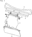
- In an upper structure of an engine of a vehicle illustrated in
Fig. 1 ,reference numeral 1 represents an engine,reference numeral 2 represents a dash panel that partitions anengine bay 3 from avehicle interior 4 behind theengine bay 3,reference numeral 5 represents a cowl panel provided above thedash panel 2, and reference numeral 6 represents a hood that covers theengine bay 3. As illustrated also inFig. 2 , acowl front panel 7 extending forward from the upper portion of thedash panel 2 is joined to the lower end portion of thecowl panel 5. As illustrated also inFig. 3 , a backheat retaining cover 8 that covers the upper portion of theengine 1 from the rear side is fixed to the front end portion of thecowl front panel 7. In addition, the rear end portion of an upperheat retaining cover 9 that covers theengine 1 from above is supported by and fixed to the upper end portion of the backheat retaining cover 8. - The heat retaining covers 8 and 9 are formed by pasting insulators made of foamed resin onto the inner surfaces of plates made of synthetic resin. In
Fig. 2 ,reference numeral 11 represents a radiator. - As illustrated in
Fig. 1 , theengine 1 is a rear exhaust engine in which anintake manifold 12 as the intake system component is disposed on the front side in a vehicle front-rear direction and anexhaust manifold 13 as the exhaust system component is disposed on the rear side. InFig. 1 ,reference numeral 14 represents a turbocharger andreference numeral 15 represents an intercooler. Between theengine 1 and the heat retaining covers 8 and 9, threeflow rectifying members 17 to 19 are disposed adjacently to each other in the vehicle front-rear direction so as to introduce traveling wind to theexhaust manifold 13. That is, the three flow rectifying members are the firstflow rectifying member 17 provided above the upper surface front portion of theengine 1, the secondflow rectifying member 18 provided behind (above the upper surface rear portion of the engine 1) of the firstflow rectifying member 17, and the thirdflow rectifying member 19 provided behind the upper portion of theengine 1. - As illustrated also in
Fig. 4 , theflow rectifying members 17 to 19 are arranged in the vehicle front-rear direction and the threeflow rectifying members 17 to 19 form, between the threeflow rectifying members 17 to 19 and theheat insulating covers Fig. 1 ) that introduces traveling wind to theexhaust manifold 13. -
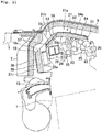
Fig. 5 is a plan view illustrating theengine 1 with the firstflow rectifying member 17 removed. Fuel system components of theengine 1 are disposed below the firstflow rectifying member 17. In this diagram,reference numeral 22 represents a common rail (fuel rail) for fuel supply that extends in a cylinder bank direction of theengine 1 andfuel supply pipes 23 that branch from thecommon rail 22 are connected to fuel injection valves of individual cylinders. - As illustrated in
Fig. 6 that is a partial enlarged view ofFig. 1 , anoil separator 24 having a cavity therein is provided below the secondflow rectifying member 18. Theoil separator 24 is formed by attaching abaffle plate 26 to the lower surface of a projectingpart 25a that projects upward from acylinder head cover 25. - The first
flow rectifying member 17 is formed by pasting aninsulator 32 made of foamed resin onto the lower surface of aplate 31 made of synthetic resin. The secondflow rectifying member 18 is formed by pasting aninsulator 34 made of foamed resin onto the upper surface of aplate 33 made of light metal (for example, aluminum alloy). The thirdflow rectifying member 19 is formed by covering the rear surface of aninsulator 35 made of foamed resin with aplate 36 made of light metal (for example, aluminum alloy). - The upper surface of the first
flow rectifying member 17 is substantially horizontal and smooth to subject traveling wind to flow regulation so that the traveling wind flows rearward along the upper surface. In addition, anopening 20 is formed between the front end of the firstflow rectifying member 17 and theengine 1 so that the traveling wind flows in the space between the firstflow rectifying member 17 and theengine 1. - The upper surface of the second
flow rectifying member 18 is a smooth inclined plane inclined downward toward the rear side to direct the traveling wind subjected to flow regulation by the firstflow rectifying member 17 to theexhaust manifold 13 as the exhaust system component along the upper surface. That is, the upper surface of theplate 33 of the secondflow rectifying member 18 is aninclined plane 33a inclined downward toward the vehicle rear side and the upper surface of theinsulator 34 pasted to theplate 33 is also aninclined plane 34a inclined downward according to the inclination of theplate 33. Theinclined planes flow rectifying member 18 face thecowl front panel 7 in the vehicle front-rear direction. - The upper surface of the third
flow rectifying member 19 is a smoothinclined plane 19a inclined downward toward the rear side so as to direct the traveling wind subjected to flow regulation by the secondflow rectifying member 18 to theexhaust manifold 13 along the upper surface. - The height of the rear end of the upper surface of the first
flow rectifying member 17 is substantially the same as that of the front end of theinsulator 34 of the secondflow rectifying member 18. Theinclined planes 34a of the secondflow rectifying member 18 is substantially flush with theinclined plane 19a of the thirdflow rectifying member 19. - In the above structure, the traveling
wind passage 21 between the heat retaining covers 8 and 9 and theflow rectifying members 17 to 19 includes afirst passage 21a that extends substantially horizontally in the vehicle front-rear direction, asecond passage 21b that is continuous with thefirst passage 21a and inclined downward toward the vehicle rear side, and athird passage 21c that is continuous with thesecond passage 21a and extends downward toward theexhaust manifold 13. - That is, the
first passage 21a is formed between the upperheat retaining cover 9 and the firstflow rectifying member 17, thesecond passage 21b is formed between the rear portion of the upperheat retaining cover 9 and the upper portion of the rearheat retaining cover 8 and the inclined planes of the secondflow rectifying member 18 and the thirdflow rectifying member 19, and thethird passage 21c is formed between the lower portion of the rearheat retaining cover 8 and the rear surface of the thirdflow rectifying member 19. -
Fig. 7 to Fig. 9 illustrate the state in which the firstflow rectifying member 17 is combined with theplate 33 of the secondflow rectifying member 18. The front end of the firstflow rectifying member 17 is provided with a hook-shaped mountingpart 37 projecting forward. This mountingpart 37 is fixed to theengine 1 as illustrated inFig. 10 . - Four
legs 41 are provided at intervals in the vehicle width direction at the front end portion of theinclined plate 33 of the secondflow rectifying member 18. Thelegs 41 are fixed to the cylinder head of theengine 1 as illustrated inFig 5 . At the rear end portion of theplate 33, four mountingparts 42 projecting rearward are provided at intervals in the vehicle width direction. The mountingparts 42 are fixed to the cylinder head of theengine 1 as illustrated inFig. 4 andFig. 5 . The upper surface of theplate 33 is smooth and the lower surface is provided with concave grooves extending in the vehicle front-rear direction to improve the bending rigidity (bending rigidity about an axis extending in the vehicle width direction). - In the third
flow rectifying member 19, as illustrated inFig. 4 , theplate 36 is fixed to the cylinder head of theengine 1 at a mountingpart 36a and theinsulator 35 is attached to theplate 36. - While the vehicle travels, a part of traveling wind that enters the
engine bay 3 from the front grille (not illustrated) of the vehicle flows into the travelingwind passage 21 formed between the heat retaining covers 8 and 9 and theflow rectifying members 17 to 19 and then flows rearward to theexhaust manifold 13. - Since traveling wind first flows through the
first passage 21a of the travelingwind passage 21 rearward along the smooth upper surface of the firstflow rectifying member 17, the traveling wind can be efficiently introduced rearward without being disturbed by fuel system components. - Next, the traveling wind subjected to flow regulation by the first
flow rectifying member 17 is subjected to flow regulation so as to be directed to theexhaust manifold 13 by flowing through thesecond passage 21b of the travelingwind passage 21 along theinclined plane 34a of the secondflow rectifying member 18 and theinclined plane 19a of the thirdflow rectifying member 19. - Next, the traveling wind subjected to flow regulation by the
inclined planes flow rectifying member 18 and the thirdflow rectifying member 19 flows through thethird passage 21c of the travelingwind passage 21 downward toward theexhaust manifold 13. - As described above, the
exhaust manifold 13 is efficiently cooled by traveling wind, excessively high temperature exhaust gas can be prevented from flowing into an exhaust gas purification catalyst even when the catalyst is disposed near theexhaust manifold 13, and thermal degradation of the catalyst is advantageously prevented. In addition, since theexhaust manifold 13 can be efficiently cooled by traveling wind as described above, a wide space for introducing traveling wind to the exhaust system component does not need to be provided above theengine 1. Accordingly, unnecessary cooling of theengine 1 can be avoided. - In addition, since a part of the traveling wind flows from the
opening 20 between theengine 1 and the front end of the firstflow rectifying member 17 into the space between theengine 1 and the firstflow rectifying member 17 as cooling air, an abnormal rise in temperature of thefuel system components - In addition, the
insulators flow rectifying members 17 to 19 prevent engine noise from entering the vehicle interior. - The
plate 36 of the thirdflow rectifying member 19 protects theinsulator 35 from the heat of theexhaust manifold 13. - Next, when the
engine 1 moves rearward due to a front collision of the vehicle, the secondflow rectifying member 18 collides with thecowl front panel 7 via the rearheat retaining cover 8 prior to the firstflow rectifying member 17. That is, an impact load is received by the secondflow rectifying member 18. Therefore, it is possible to prevent direct application of a large impact load to the firstflow rectifying member 17 and the fuel system components (common rail 22 and fuel pipe 23) provided below the firstflow rectifying member 17. Accordingly, destruction of the fuel system components due to deformation of the firstflow rectifying member 17 and destruction of the fuel system components due to the impact load described above are advantageously prevented. - In addition, since the portion of the
cowl front panel 7 that makes contact with the secondflow rectifying member 18 is theinclined plane 33a of theplate 33 during the front collision, thecowl front panel 7 slides on theinclined plane 33a and is deformed upward. That is, the force applied from thecowl front panel 7 to the secondflow rectifying member 18 is released upward along theinclined plane 33a. Accordingly, the impact received by the secondflow rectifying member 18 becomes smaller. Accordingly, the firstflow rectifying member 17 and thefuel system components flow rectifying member 18. - In addition, when the
plate 33 of the secondflow rectifying member 18 is deformed due to a collision with thecowl front panel 7 during the front collision, theoil separator 24 below theplate 33 is deformed along with the deformation. Accordingly, an impact is absorbed by the deformation of theoil separator 24 and the firstflow rectifying member 17 and thefuel system parts - It should be noted here that the material of a
plate 31 of the firstflow rectifying member 17 is not limited to synthetic resin and may be metal such as light alloy or plate steel. - The material of the
plate 33 of the secondflow rectifying member 18 and theplate 36 of the thirdflow rectifying member 19 is not limited to light alloy, but may be synthetic resin or plate steel. -
Fig. 11 illustrates a main portion of a structure according to another embodiment. This embodiment is different from the above embodiment having the firstflow rectifying member 17 and secondflow rectifying member 18 that are separated from each other in that this embodiment is provided with oneflow rectifying member 51 having the functions of theflow rectifying members - The
flow rectifying member 51 includes a firstflow rectifying part 52 that subjects traveling wind to flow regulation so that the traveling wind flows rearward along the upper surface thereof and a secondflow rectifying part 53 disposed continuously behind the firstflow rectifying part 52. The secondflow rectifying part 53 subjects the traveling wind subjected to flow regulation by the firstflow rectifying part 52 to flow regulation so that the traveling wind is directed to the exhaust system component (exhaust manifold) along the upper surface thereof and is inclined downward toward the vehicle rear side. - The
fuel system components engine 1 are disposed below the firstflow rectifying part 52. Theoil separator 24 is disposed below the secondflow rectifying part 53. - The first
flow rectifying part 52 is formed by pasting aninsulator 55 made of foamed resin onto the lower surface of afront portion 54a of aplate 54 made of light metal (for example, aluminum alloy). The secondflow rectifying part 53 is formed by pasting aninsulator 56 made of foamed resin onto the upper surface of arear portion 54b of theplate 54. - The
front portion 54a of theplate 54 extends substantially horizontally in the vehicle front-rear direction and the upper and lower surfaces thereof are smooth. Therear portion 54b of theplate 54 is inclined downward from the rear end of thefront portion 54a via a bent portion and a plurality ofstructure beads 57 extending in the inclination direction are provided at intervals in the vehicle width direction. That is, therear portion 54b of theplate 54 has a corrugated shape with the plurality ofstructural beads 57, so the bending rigidity (bending rigidity about an axis extending in the vehicle width direction) is higher than in thefront portion 54a of theplate 54. In addition, the inclined upper surface of theinsulator 56 of the secondflow rectifying part 53 is smooth. - The present embodiment can also obtain the same effect concerning the regulation of traveling wind as the above embodiment.
- When the
engine 1 is moved rearward due to a front collision of the vehicle and theflow rectifying member 51 collides with thecowl front panel 7, an impact load is received by theinclined plane 58 of the platerear portion 54b having a high rigidity of thesecond rectifying portion 53. Therefore, direct application of a large impact load to the firstflow rectifying part 52 and thefuel system components fuel system components flow rectifying part 52 or destruction of thefuel system components - In addition, since the rigidity of the second
flow rectifying part 53 is high, when thecowl front panel 7 makes contact with the inclined plane of the secondflow rectifying part 53, thecowl front panel 7 slides on the inclined plane and is easily deformed upward. That is, the force applied from thecowl front panel 7 to the secondflow rectifying part 53 is easily released upward along the inclined plane. - The second
flow rectifying part 53 may have a higher rigidity by making the plate thickness thicker than in the first flow rectifyingpart unit 52. - In addition, the material of the
flow rectifying member 51 is not limited to light alloy, but may be plate steel or synthetic resin. -
- 1:
- engine
- 2:
- dash panel
- 3:
- engine bay
- 4:
- vehicle interior
- 5:
- cowl panel
- 6:
- hood
- 7:
- cowl front panel
- 8, 9:
- heat retaining cover
- 13:
- exhaust manifold (exhaust system component)
- 17:
- first flow rectifying member
- 18:
- second flow rectifying member
- 19:
- third flow rectifying member
- 20:
- opening
- 22:
- fuel supply common rail (fuel system component)
- 23:
- fuel supply pipe (fuel system component)
- 24:
- oil separator
- 33a:
- inclined plane
- 34a:
- inclined plane
- 51:
- flow rectifying member
- 52:
- first flow rectifying part
- 53:
- second flow rectifying part
- 57:
- structure bead
Claims (10)
- An upper structure of a rear exhaust engine provided with an exhaust system component behind the engine in a vehicle front-rear direction, the upper structure comprising:a first flow rectifying member provided above the engine, the first flow rectifying member subjecting traveling wind to flow regulation so that the traveling wind flows rearward along an upper surface thereof; anda second flow rectifying member provided behind the first flow rectifying member, the second flow rectifying member subjecting the traveling wind subjected to flow regulation by the first flow rectifying member to flow regulation so that the traveling wind is directed to the exhaust system component along an upper surface thereof,wherein a fuel system component of the engine is disposed below the first flow rectifying member.
- The upper structure of the engine according to claim 1,
wherein a cowl member extending forward from an upper portion of a dash panel is provided behind the second flow rectifying member,
the second flow rectifying member has an inclined plane inclined downward toward a rear side to direct the traveling wind to the exhaust system component, and
the cowl member faces the inclined plane of the second flow rectifying member in the vehicle front-rear direction. - The upper structure of the engine according to claim 1 or 2,
wherein an oil separator having a cavity therein is provided below the second flow rectifying member. - The upper structure of the engine according to any one of claims 1 to 3,
wherein a cover member that covers the second flow rectifying member is provided between the second flow rectifying member and a hood so that a gap through which the traveling wind passes is present. - The upper structure of the engine according to any one of claims 1 to 4,
wherein an opening is provided between the engine and a front end of the first flow rectifying member so that the traveling wind flows in a space between the engine and the first flow rectifying member. - An upper structure of a rear exhaust engine provided with an exhaust system component behind the engine in a vehicle front-rear direction, the upper structure comprising:a flow rectifying member provided above the engine, the flow rectifying member subjecting traveling wind to flow regulation so that the traveling wind is directed to the exhaust system component along an upper surface thereof,wherein the flow rectifying member includes a first flow rectifying part and a second flow rectifying part provided behind the first flow rectifying part,a fuel system component of the engine is disposed below the first flow rectifying part, andthe second flow rectifying part has a rigidity higher than the first flow rectifying part.
- The upper structure of the engine according to claim 6,
wherein a cowl member extending forward from an upper portion of a dash panel is provided behind the second flow rectifying part,
the second flow rectifying part has an inclined plane inclined downward toward a rear side to direct the traveling wind to the exhaust component, and
the cowl member faces the inclined plane of the second flow rectifying part in the vehicle front-rear direction. - The upper structure of the engine according to claim 6 or 7,
wherein an oil separator having a cavity therein is provided below the second flow rectifying part. - The upper structure of the engine according to any one of claims 6 to 8,
wherein a cover member that covers the second flow rectifying part is provided between the second flow rectifying part and a hood so that a gap through which the traveling wind passes is present. - The upper structure of the engine according to any one of claims 6 to 9,
wherein an opening is provided between the engine and a front end of the flow rectifying member so that the traveling wind flows in a space between the engine and the flow rectifying member.
Applications Claiming Priority (2)
| Application Number | Priority Date | Filing Date | Title |
|---|---|---|---|
| JP2017059474A JP6432631B2 (en) | 2017-03-24 | 2017-03-24 | Engine superstructure |
| PCT/JP2018/005147 WO2018173556A1 (en) | 2017-03-24 | 2018-02-15 | Upper structure for engine |
Publications (2)
| Publication Number | Publication Date |
|---|---|
| EP3578402A1 true EP3578402A1 (en) | 2019-12-11 |
| EP3578402A4 EP3578402A4 (en) | 2020-01-15 |
Family
ID=63584311
Family Applications (1)
| Application Number | Title | Priority Date | Filing Date |
|---|---|---|---|
| EP18771650.1A Pending EP3578402A4 (en) | 2017-03-24 | 2018-02-15 | Upper structure for engine |
Country Status (5)
| Country | Link |
|---|---|
| US (1) | US10913347B2 (en) |
| EP (1) | EP3578402A4 (en) |
| JP (1) | JP6432631B2 (en) |
| CN (1) | CN110662666B (en) |
| WO (1) | WO2018173556A1 (en) |
Families Citing this family (2)
| Publication number | Priority date | Publication date | Assignee | Title |
|---|---|---|---|---|
| JP7359017B2 (en) | 2020-02-13 | 2023-10-11 | マツダ株式会社 | Vehicle front structure |
| CN114017172A (en) * | 2021-11-15 | 2022-02-08 | 中国第一汽车股份有限公司 | Engine air cooling system and vehicle with same |
Family Cites Families (19)
| Publication number | Priority date | Publication date | Assignee | Title |
|---|---|---|---|---|
| JPH035023U (en) | 1989-06-05 | 1991-01-18 | ||
| JPH0350523U (en) * | 1989-09-26 | 1991-05-16 | ||
| JP3287584B2 (en) * | 1991-03-25 | 2002-06-04 | ヤマハ発動機株式会社 | Arrangement structure of auxiliary equipment in ship propulsion |
| WO2004081386A1 (en) * | 2003-03-13 | 2004-09-23 | Yanmar Co., Ltd. | Cover structure for engine |
| US7011071B1 (en) * | 2004-10-27 | 2006-03-14 | Decuir Jr Julian A | Internal boost system for engines |
| JP2007055274A (en) * | 2005-08-22 | 2007-03-08 | Mazda Motor Corp | Front structure of vehicle body |
| JP2008013149A (en) * | 2006-07-10 | 2008-01-24 | Honda Motor Co Ltd | Baffle plate for vehicle |
| JP4811412B2 (en) * | 2008-01-17 | 2011-11-09 | トヨタ自動車株式会社 | Oil separator |
| JP5267089B2 (en) * | 2008-12-05 | 2013-08-21 | トヨタ自動車株式会社 | Exhaust system cooling structure |
| KR101315713B1 (en) * | 2011-12-07 | 2013-10-10 | 기아자동차주식회사 | Engine encapsulation structure of vehicle |
| JP5737301B2 (en) * | 2013-01-11 | 2015-06-17 | トヨタ自動車株式会社 | Ventilation structure for vehicles |
| FR3007080B1 (en) * | 2013-06-17 | 2019-05-17 | Suzuki Motor Corporation | OUTBOARD ENGINE INTAKE STRUCTURE |
| JP6380212B2 (en) * | 2014-12-09 | 2018-08-29 | 株式会社デンソー | Cooling device and cooling module |
| JP2016130074A (en) * | 2015-01-13 | 2016-07-21 | トヨタ自動車株式会社 | Vehicular air introduction structure |
| JP2017013638A (en) * | 2015-07-01 | 2017-01-19 | スターライト工業株式会社 | Cooling control structure of engine compartment |
| US9840144B2 (en) * | 2015-08-19 | 2017-12-12 | Mazda Motor Corporation | Front air-rectifying structure of automotive vehicle |
| DE112016003786T5 (en) * | 2015-08-20 | 2018-05-09 | Denso Corporation | cooler |
| US10006336B2 (en) * | 2015-10-27 | 2018-06-26 | Suzuki Motor Corporation | Saddle-ridden vehicle |
| JP6292265B2 (en) * | 2016-09-07 | 2018-03-14 | マツダ株式会社 | Superstructure of vehicle engine |
-
2017
- 2017-03-24 JP JP2017059474A patent/JP6432631B2/en active Active
-
2018
- 2018-02-15 EP EP18771650.1A patent/EP3578402A4/en active Pending
- 2018-02-15 US US16/490,865 patent/US10913347B2/en active Active
- 2018-02-15 WO PCT/JP2018/005147 patent/WO2018173556A1/en unknown
- 2018-02-15 CN CN201880015855.8A patent/CN110662666B/en active Active
Also Published As
| Publication number | Publication date |
|---|---|
| JP6432631B2 (en) | 2018-12-05 |
| JP2018161932A (en) | 2018-10-18 |
| CN110662666A (en) | 2020-01-07 |
| US10913347B2 (en) | 2021-02-09 |
| EP3578402A4 (en) | 2020-01-15 |
| CN110662666B (en) | 2022-12-27 |
| WO2018173556A1 (en) | 2018-09-27 |
| US20200031217A1 (en) | 2020-01-30 |
Similar Documents
| Publication | Publication Date | Title |
|---|---|---|
| EP2917059B1 (en) | Air guide structure for an engine compartment of a vehicle | |
| US7958966B2 (en) | Exhaust stack fairing | |
| US20040163874A1 (en) | Rear covering part with a tail pipe orifice | |
| US8511411B2 (en) | Cooling module for motor vehicles and motor vehicle | |
| JP6922763B2 (en) | Vehicle undercarriage | |
| US10913347B2 (en) | Upper structure of engine | |
| JP5375082B2 (en) | Cooling structure for vehicle intercooler | |
| JP6465139B2 (en) | Lower body structure of the vehicle | |
| JP2008137591A (en) | Vehicular body front part structure | |
| CN112109809B (en) | Vehicle engine compartment structure | |
| JP6536668B1 (en) | engine | |
| JP2008095527A (en) | Exhaust device for internal combustion engine | |
| CN108136974B (en) | Assembly for a motor vehicle chassis | |
| JP4622491B2 (en) | Heat-damage prevention structure for automobile cowl | |
| JP2005282488A (en) | Air intake device for vehicular engine | |
| JP5531917B2 (en) | Ventilation structure for vehicles | |
| DE102013202667A1 (en) | Motor vehicle with an exhaust system | |
| JP2019120123A (en) | engine | |
| JP2020023258A (en) | Vehicle underfloor structure | |
| CN217553832U (en) | Automobile rear assembly and automobile | |
| JP6790993B2 (en) | Vehicle front structure | |
| JP6837605B2 (en) | Mounting structure for automobiles including brackets with low rigidity for vehicle safety | |
| JP2007153236A (en) | Shock absorbing structure of vehicle | |
| JP4370895B2 (en) | Heat shield for automobile exhaust system | |
| JP2023077450A (en) | vehicle structure |
Legal Events
| Date | Code | Title | Description |
|---|---|---|---|
| STAA | Information on the status of an ep patent application or granted ep patent |
Free format text: STATUS: THE INTERNATIONAL PUBLICATION HAS BEEN MADE |
|
| PUAI | Public reference made under article 153(3) epc to a published international application that has entered the european phase |
Free format text: ORIGINAL CODE: 0009012 |
|
| STAA | Information on the status of an ep patent application or granted ep patent |
Free format text: STATUS: REQUEST FOR EXAMINATION WAS MADE |
|
| 17P | Request for examination filed |
Effective date: 20190905 |
|
| AK | Designated contracting states |
Kind code of ref document: A1 Designated state(s): AL AT BE BG CH CY CZ DE DK EE ES FI FR GB GR HR HU IE IS IT LI LT LU LV MC MK MT NL NO PL PT RO RS SE SI SK SM TR |
|
| AX | Request for extension of the european patent |
Extension state: BA ME |
|
| A4 | Supplementary search report drawn up and despatched |
Effective date: 20191213 |
|
| RIC1 | Information provided on ipc code assigned before grant |
Ipc: F01M 13/04 20060101ALN20191209BHEP Ipc: B62D 25/08 20060101ALI20191209BHEP Ipc: B60K 11/06 20060101AFI20191209BHEP Ipc: F01P 1/00 20060101ALN20191209BHEP Ipc: F01P 1/06 20060101ALI20191209BHEP Ipc: B60K 11/04 20060101ALI20191209BHEP Ipc: F02B 77/11 20060101ALI20191209BHEP |
|
| DAV | Request for validation of the european patent (deleted) | ||
| DAX | Request for extension of the european patent (deleted) | ||
| STAA | Information on the status of an ep patent application or granted ep patent |
Free format text: STATUS: EXAMINATION IS IN PROGRESS |
|
| 17Q | First examination report despatched |
Effective date: 20220926 |
|
| GRAP | Despatch of communication of intention to grant a patent |
Free format text: ORIGINAL CODE: EPIDOSNIGR1 |
|
| STAA | Information on the status of an ep patent application or granted ep patent |
Free format text: STATUS: GRANT OF PATENT IS INTENDED |
|
| RIC1 | Information provided on ipc code assigned before grant |
Ipc: F01P 1/00 20060101ALN20231120BHEP Ipc: F01M 13/04 20060101ALN20231120BHEP Ipc: B60K 13/04 20060101ALI20231120BHEP Ipc: F02B 77/11 20060101ALI20231120BHEP Ipc: F01P 1/06 20060101ALI20231120BHEP Ipc: B62D 25/08 20060101ALI20231120BHEP Ipc: B60K 11/04 20060101ALI20231120BHEP Ipc: B60K 11/06 20060101AFI20231120BHEP |
|
| RIC1 | Information provided on ipc code assigned before grant |
Ipc: F01P 1/00 20060101ALN20231127BHEP Ipc: F01M 13/04 20060101ALN20231127BHEP Ipc: B60K 13/04 20060101ALI20231127BHEP Ipc: F02B 77/11 20060101ALI20231127BHEP Ipc: F01P 1/06 20060101ALI20231127BHEP Ipc: B62D 25/08 20060101ALI20231127BHEP Ipc: B60K 11/04 20060101ALI20231127BHEP Ipc: B60K 11/06 20060101AFI20231127BHEP |
|
| INTG | Intention to grant announced |
Effective date: 20231214 |
|
| GRAS | Grant fee paid |
Free format text: ORIGINAL CODE: EPIDOSNIGR3 |
|
| GRAA | (expected) grant |
Free format text: ORIGINAL CODE: 0009210 |
|
| STAA | Information on the status of an ep patent application or granted ep patent |
Free format text: STATUS: THE PATENT HAS BEEN GRANTED |