EP3578393A1 - Spike - Google Patents
Spike Download PDFInfo
- Publication number
- EP3578393A1 EP3578393A1 EP19172154.7A EP19172154A EP3578393A1 EP 3578393 A1 EP3578393 A1 EP 3578393A1 EP 19172154 A EP19172154 A EP 19172154A EP 3578393 A1 EP3578393 A1 EP 3578393A1
- Authority
- EP
- European Patent Office
- Prior art keywords
- spike
- plane
- upper flange
- sub
- flange
- Prior art date
- Legal status (The legal status is an assumption and is not a legal conclusion. Google has not performed a legal analysis and makes no representation as to the accuracy of the status listed.)
- Granted
Links
Images


Classifications
-
- B—PERFORMING OPERATIONS; TRANSPORTING
- B60—VEHICLES IN GENERAL
- B60C—VEHICLE TYRES; TYRE INFLATION; TYRE CHANGING; CONNECTING VALVES TO INFLATABLE ELASTIC BODIES IN GENERAL; DEVICES OR ARRANGEMENTS RELATED TO TYRES
- B60C11/00—Tyre tread bands; Tread patterns; Anti-skid inserts
- B60C11/14—Anti-skid inserts, e.g. vulcanised into the tread band
- B60C11/16—Anti-skid inserts, e.g. vulcanised into the tread band of plug form, e.g. made from metal, textile
- B60C11/1643—Anti-skid inserts, e.g. vulcanised into the tread band of plug form, e.g. made from metal, textile with special shape of the plug-body portion, i.e. not cylindrical
Definitions
- the invention relates to a spike for anchoring in the tread of a vehicle tire with a top flange, a celebrityflansch and a Spikepin, wherein the crabflansch has at least one symmetry plane and at least two in plan view symmetrically to the plane of symmetry extending, flat side surfaces, wherein the Spikepin and / or the upper flange with respect the symmetry plane of the base flange and / or with respect to a plane perpendicular to this plane of symmetry, the second axis containing the main axis of the spike are asymmetrical or is.
- a spike with a foot flange of the type mentioned above has two mutually parallel side surfaces which extend symmetrically in plan view with respect to a plane containing the main axis of the spike.
- a spike with a spike pin is known, which is an elongated body in plan view on its upper side, wherein the body has only one plane of symmetry, which halves the spike pin perpendicular to the top and in the longitudinal direction of the spike pin.
- the spike pin is therefore designed asymmetrically with respect to each plane perpendicular to the plane of symmetry.
- Spikes of the type mentioned above are disclosed in the filed on behalf of Continental Reifen Anlagen GmbH recently filed with the European Patent Office, not yet published applications.
- Such spikes for example, from the WO 2015/139860 A1 known Spikepin in combination with the from the DE 10 2015 223 091 A1 have known foot flange.
- a spike with an asymmetrical spike pin and / or an asymmetric upper flange has a particularly advantageous orientation on the tread of a pneumatic vehicle tire-in terms of driving characteristics.
- the spike gun In order to insert the spike into the tread in its preferred orientation, it is necessary to transport the spike in a defined position to the spike gun.
- spike conveyors for example vibratory conveyors, it is not possible to place spikes in a defined position or orientation on a transport device leading to a spiked setting gun. The position of the spike on the transport device could be checked by means of a camera system.
- a reliable distinction is often not possible or not reliable. If spikes are asymmetrical only with regard to the cross section of their spike pin, it is currently not possible to reliably detect the correct spike position on the transport device.
- the invention is therefore based on the object to provide a spike of the type mentioned in which the position or orientation of the spike on a transport device is reliably detected.
- the object is achieved according to the invention by the fact that at least one orientation element is formed on the upper flange of the spike, which gives the spike lying on a flat side surface of the base flange an asymmetrical silhouette which is symmetrical to the plane of the foot flange.
- the spike When transporting a spike according to the invention from a storage container to a feed tube leading to the spiked setting gun, its position can be reliably detected along the transport path by means of a camera system.
- the spike will lie on the transport device on one of the flat side surfaces of its foot flange. Due to the asymmetrical silhouette of the spike, the camera system is able to detect the orientation of the spike on the transport device.
- An incorrectly oriented spike is removed from the transport device, for example by means of an air pressure surge, so that it can be ensured that only correctly oriented spikes reach the feed tube of the spike gun and the spike subsequently in the desired orientation is used in the tread.
- the orientation elements formed on the spikes according to the invention have no influence on the ballast stiffness of the spike. In addition, the orientation elements can be made very small, since even small changes in the silhouette are sufficient for reliable detection, so that the orientation elements do not affect the snow and ice gripping properties of the spikes.
- the orientation element formed on the upper flange preferably adjoins the base flange.
- the orientation element formed on the upper flange, in plan view of the spike is a projection which does not project beyond the base flange.
- a projection takes no or almost no influence on the other properties of the spike.
- the projection is crescent-shaped in plan view of the spike, since such a shaped projection rests particularly well on the upper flange.
- the projection has a curved surface which is inclined in the second plane at an angle to the main axis of the spike, the angle to the sickle ends of the sickle shape of the projection decreases continuously and wherein the surface at the sickle ends via plane, inclined to the main axis transition surfaces tangentially into the lateral surface of the upper flange.
- a projection is almost one with the upper flange, so it is particularly ideal adapted to the geometry.
- the projection has a thickness of 0.1 mm to 1.0 mm, in particular of up to 0.5 mm, at its thickest point.
- the orientation element formed on the upper flange is formed by a recess and a projecting elevation, wherein the recess and the elevation have a common boundary surface. Even such an orientation element takes no or almost no influence on the other properties of the spike.
- orientation elements formed from depression and superelevation can be used in a very versatile manner and are particularly advantageous especially in the case of more complex surface flange shapes.
- the boundary surface is designed such that the recess is sickle-shaped in cross-section and when the boundary surface extends in the region of the elevation in cross-section at least partially straight. In particular, this gives the silhouette a characteristic and easily detectable straight line.
- the depression at its lowest point has a depth of 0.1 mm to 1.0 mm, in particular of up to 0.5 mm, and if the elevation at its thickest point has a thickness of 0.1 mm 1.0 mm, in particular up to 0.5 mm.
- a further preferred embodiment variant is characterized in that the orientation element formed on the upper flange is a bevel formed on the edge of the upper side of the upper flange and forming an inclined surface. Such a chamfer gives the silhouette a line inclined to the main axis of the spike.
- the orientation element formed on the upper flange is a rounding formed on the edge of the upper side of the upper flange. Such a rounding gives the silhouette of the spike at the edge of the upper surface of the upper flange a characteristic, detectable radius.
- the orientation element formed on the upper flange has a length of 0.5 mm to 8.0 mm, in particular 2.0 mm to 5.0 mm, determined parallel to the main axis of the spike.
- Such an orientation element has a certain minimum size, as a result of which the position of "particularly unfavorable", for example oblique, spikes lying on the transport device can be reliably detected by means of the camera system. A possible “shading" of the orientation element is particularly unlikely.
- the second plane is a plane of symmetry of the orientation element.
- the second level contains the main axis of the spike and is perpendicular to at least one plane of symmetry of the tillflansches.
- the orientation element formed on the upper flange, in plan view of the spike and with respect to the main axis of the spike extends over a central angle of 10 ° to 180 °, in particular of at least 90 °.
- the orientation element gives the spike, on the one hand, the above-mentioned asymmetric silhouette and on the other hand, its size is limited to a manner advantageous for the ballast stiffness of the spike.
- the central angle over which the orientation element extends in plan view and with respect to the main axis of the spike 360 n ⁇ 1 ° .
- n 2, 3, 4, 5 or 6.
- Fig. 1a and Fig. 1b show a spike 1 with a foot flange 2, a top flange 3 and a spike pin 4. Further, in Fig. 1a and Fig. 1b in the vertical position of the spike 1 extending in the vertical direction of the main axis a 1 of the spikes 1 on or marked.
- the foot flange 2 has in plan view ( Fig. 1b ) has a substantially oval shape and two in the longer extension of the oval parallel to each other extending, planar side surfaces 2a, 2b and two rounded side surfaces 2c, 2d. How Fig.
- FIG. 1b shows, the foot flange 2 a aligned in its longitudinal extent, parallel to the flat side surfaces 2a, 2b and through the main axis a 1 of the spike 1 extending symmetry plane E 1 , which in Fig. 1b corresponds to a vertical line. Furthermore, the spike 1 and thus also the foot flange 2 through the main axis a 1 (see in particular Fig. 1c ) and orthogonal to the plane of symmetry E 1 extending second plane of symmetry E 2 , which in Fig. 1b corresponds to a horizontal line.
- Fig. 1a shows the upper flange 3 in the embodiment shown circular cylindrical or at least approximately circular cylindrical, has a lateral surface 3a and is located centrally on the foot flange 2.
- the spike pin 4 is anchored substantially centrally in the upper flange 3, protrudes from this in a known manner and is oriented in plan view transversely to the longer extension of said oval of the base flange 2 ( Fig. 1b ).
- Fig. 1b has the spike pin 4 at least outside the upper flange 3 with respect to the symmetry plane E 2 symmetrical hexagonal cross-section.
- the hexagonal cross-section of the spike pin 4 is asymmetrical in such a way that Fig. 1b in the right spike half 1a formed by the plane of symmetry E 1 , two corners of the hexagon of the cross section and in the left spike half 1b formed by the plane of symmetry E 1 are four corners of the hexagon.
- the desired and preferred orientation of the spike 1 in the tread of a pneumatic vehicle tire is such that the spike half 1a is closer to the tire equatorial plane than the spike half 1b, wherein the plane of symmetry E 1 is inclined in plan view to the circumferential direction at a small acute angle.
- the spike half 1b is the spike half on the outside of the tread and the spike half 1a is the spike half on the inside of the tread.
- Fig. 1a in combination with Fig. 1b shows, in the lower half of the upper flange 3 on the lateral surface 3a, a foot flange 2 contacting and this not outstanding, flat projection 5 is formed, which, as will be explained, serves as an orientation element.
- the projection 5 is mitge supported in the production of the spike 1 and therefore preferably consists of the respective material of the upper flange. 3
- the projection 5 extends in plan view of the spike 1 symmetrical to the plane of symmetry E 2 , wherein the projection 5 in the embodiment shown extends over the entire tread inside spike half 1a and therefore over half the circumference of the circular cylindrical upper flange 3.
- the projection 5 extends in plan view and with respect to the main axis a 1 via a central angle ⁇ of 180 ° ⁇ 1 °.
- the projection 5 is substantially crescent-shaped in plan view, further has an elongated, triangular cross-section and is bounded by a curved surface 5a.
- the curved surface 5a is inclined to the main axis a 1 of the spike 1 at an acute angle which decreases continuously starting from the plane E 2 to the two sickle ends 5b of the sickle shape of the projection 5, wherein the surface 5a at the sickle ends 5b above plane, to Main axis a 1 inclined transition surfaces 5c tangentially merges into the lateral surface of the upper flange 3 ( Fig. 1b ).
- the projection 5 has in the extension direction of the major axis a 1, a length l 1 ( Fig. 1c ) of 0.5 mm to 8.0 mm, especially 2.0 mm to 5.0 mm, and more preferably about 3.0 mm.
- the projection 5 At its end located at the foot flange 2, the projection 5 at its thickest and at the same time in the plane of symmetry E 2 lying point opposite the level of the lateral surface of the upper flange 3 determined thickness d 1 ( Fig. 1b ) of 0.1 mm to 1.0 mm, in particular of up to 0.5 mm, and in the illustrated embodiment of 0.4 mm.
- spikes 1 To use the spikes 1 in the stud holes of a tread a pneumatic vehicle tire, accumulated in a storage container spikes 1, for example by means of a vibrating conveyor, applied to a transport device on which the spikes 1 with her foot flange 2 ahead, lying flat to a to a Spiked gun leading feed pipe to be transported.
- the cross section of the feed tube is tuned in a known manner to the respective spike geometry, so that asymmetrical spikes in the feed tube can not twist.
- the spike 1 can pass through the feed tube in two possible orientations.
- the spike 1 is - depending on the orientation - subsequently either inserted into the Laustsammlung so that the spike half 1a, as desired, closer to the tire equatorial plane than the spike half 1b or in exactly opposite position of the spike halves 1a, 1b.
- Fig. 1c and Fig. 1d the projection 5 described serves as an orientation element.
- Fig. 1c and Fig. 1d is indicated by a line T 1
- the transport direction is indicated by an arrow P 1 .
- a spike 1 applied to the transport device will lie on one of the two flat side surfaces 2a, 2b, since it "rolls over" correspondingly over the rounded side surfaces 2c, 2d.
- Fig. 1c shows the spike 1 lying on the flat side surface 2a
- Fig. 1d shows the spike 1 lying on the flat side surface 2b.
- Relative to the transport direction of the spike 1 is aligned with its foot flange 2 ahead, with such alignment in a known manner with high reliability is possible.
- whether the spike 1 lies on the side surface 2a or on the side surface 2b is not controllable by chance and with the currently customary conveying devices.
- the exact location of the spike 1 directly affects its subsequent orientation on the tread.
- the in Fig. 1c shown position of the spike 1 the desired setting for the setting
- the in Fig. 1d shown location of the spike 1 the undesirable for the setting process location.
- the spike 1 is guided past the transport device on a camera system, not shown in the figures, which picks up and analyzes the silhouette of the spike 1. Like a comparison of Fig. 1c with the Fig. 1d shows, the projection 5 gives the spike 1 a dependent on the position of the spike 1 silhouette. The analysis of the recorded silhouette is made by comparison with a "reference shadow", which was previously recorded. If the camera system detects a spike 1 in the position desired for the setting process ( Fig. 1c ), the spike 1 is transported on to the feed tube. Does the camera system detect a spike 1 in the position that is undesirable for the setting process ( Fig. 1d ), the spike 1, in particular via a coming from a corresponding nozzle air pressure shock, transported by the transport device back into the reservoir.
- Fig. 2a and Fig. 2b show a spike 1 'with a foot flange 2', a top flange 3 'and a spike pin 4'.
- the foot flange 2 ' has in plan view ( Fig. 2b ) has a substantially oval shape and two extending in the longer extension of the oval, flat side surfaces 2'a, 2'b and two rounded side surfaces 2'c, 2'd. How Fig.
- FIG. 2b shows, the foot flange 2 a aligned in its longitudinal extent and by the upright in the upright position of the spike 1 in the vertical direction oriented main axis a 1 'of the spike 1' extending plane of symmetry E 1 ', which in Fig. 2b corresponds to a vertical line.
- the planar side surfaces 2'a, 2'b are inclined in plan view with respect to the plane of symmetry E 1 'so that the width of the base flange 2' continuously decreases over the longer extension of the oval, so that the rounded side surface 2'c is longer than the rounded side Side surface 2'd.
- the upper flange 3 ' is positioned in the middle region of the base flange 2' and, in the embodiment shown, is cylindrical and has an upper part 3'a with a constant diameter and a lower part 3'b (FIG. Fig. 2a ), whose diameter starting from the diameter of the upper part 3'a direction foot flange 2 'is slightly lower.
- the top flange 3 ' is in plan view of the spike 1' on all sides of the foot flange 2 ', in part only slightly, surmounted ( Fig. 2b ).
- the upper part 3'a of the upper flange 3 ' has an interrupted by two recesses 6', 7 'and otherwise flat, parallel to theticianflansch 2' or its upper side extending top 9 ', the outside of narrow, direction foot flange 4 sloping sloping extending edge portions 9'a is limited.
- the recesses 6 ', 7' in plan view in each case symmetrically to the plane of symmetry E 1 'running and with respect to the main axis a 1 ' offset by 180 ° to each other, so that they are separated by the spike pin 4 '.
- the recesses 6 ', 7' extend from the spike pin 4 'to the edge of the upper flange 3', at which they terminate open, and each have a parallel to the main axis a 1 'determined depth of 0.5 mm to 2.0 mm ,
- Each recess 6 ', 7' is in plan view substantially U-shaped and bounded by two, one leg of the U-forming, up to the spike pin 4 'extending, planar boundary walls 8'.
- the boundary walls 8 'of the recess 6' extend in plan view at an angle ⁇ 'of in particular up to 20 ° Symmetrieebene E 1 ', wherein the recess 6' starting from the spike pin 4 'in the direction of its open end at the edge of the upper flange 3' is continuously wider.
- the boundary walls 8 'of the recess 7 "extend in a plan view substantially parallel to the plane of symmetry E 1 ',
- the volume of the recess 7 ' is greater than the volume of the recess 6'
- the different volumes of the recesses 6 ', 7' are responsible for their function
- the recesses 6 ', 7' act as drainage channels or reservoirs for the removal or picking up of ice chips, which are formed on icy road surfaces when the spikes 1 'are pulled through ice when they are rolled off
- the desired and preferred orientation of the spike 1 'in the tread of a pneumatic vehicle tire is such that the plane of symmetry E 1 ' in plan view is aligned in the circumferential direction, wherein, in a directional tread designed tread, the rolling of the tire, the longer side surface 2'c, which at inserted spike 1 'is embedded in the rubber of the tread, in front of the embedded with the spike 1' also embedded in the rubber of the tread, shorter side surface 2'd in the ground or in the ground contact surface should occur.
- Fig. 2a shows, at the lower end of the lower part 3'b of the upper flange 3 'to the base flange 2' a transitional rounded 10 'is formed, which is interrupted in sections in the region of the extension of the flat side surface 2'a. In the area of the interruption, the lower part 3'b has a specially running boundary surface 5 '.
- Fig. 2e shows the spike 1 'in upright positions, wherein a dashed auxiliary line h l is located, which corresponds to the on the boundary surface 5' continued, "imaginary", otherwise present outer contour of the lower part 3'b.
- Fig. 2e shows, limited the boundary surface 5 'at the same time a directly to the foot flange 2' adjacent, in the lower part 3'b projecting shallow recess 5'a and an adjacent to this, formed on the lower part 3'b elevation 5'b, which compared to the "imaginary" outer contour (auxiliary line h l ) is a very flat projection.
- the depression 5'a is substantially crescent-shaped in cross-section and has a depth t 1 of 0.1 mm to 1.0 mm, in particular from to the level of the transitional rounding 10 'or the level of the upper flange 3' at its lowest point to 0.5 mm, on.
- the elevation 5'b has over the level of the upper flange 3 at its thickest point a thickness d 1 of 0.1 mm to 1.0 mm, in particular of up to 0.5 mm.
- the boundary surface 5 'extends symmetrically with respect to a through the main axis a 1 ' and orthogonal to the plane of symmetry E 1 'extending plane E 2 '.
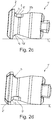
- Fig. 2c and Fig. 2d show the possible lying layers of the spike 1 'on the leading to a feed tube transport device (T 1 ). Like a comparison of Fig. 2c with the Fig. 2d shows the depression 5'a and the elevation 5'b the spike 1 'dependent on its location on the transport device silhouette.
- the depression 5'a gives the shadow outline of the spike 1'to the foot flange 2 'a radius r 1 .
- the shadow contour of the spike 1 ' has a radius r 2 which is greater than the radius r 1 .
- the elevation 5'b gives the shadow outline a straight line l adjacent to the radius r 1 .
- the combination of radius r 1 and adjacent line l is reliably distinguishable from the radius r 2 by means of a camera system, so that only the spikes 1 'oriented correctly on the transport device for the setting process are transported to the feed tube leading to the spiked setting gun.
- orientation elements can have a shape deviating from the described shape and can be arranged or formed at any point of the upper flange.
- a bevel formed on the edge of the upper side of the upper flange may be provided.
- the chamfer is or forms a curved inclined surface, which extends in cross section at a constant angle to the main axis of the spike and gives the silhouette of the spike a line inclined to the main axis.
- Such a chamfer could, for example, on a substantially circular cylindrical upper flange, as in Fig. 1a is shown, be formed and in particular have a decreasing to their free ends, determined in cross-section width.
- the orientation element can be a rounding formed on the edge of the upper side of the upper flange, in particular, the radius of the rounding over the course of the rounding starting from the corresponding plane of symmetry decreasing uniformly.
- a rounding gives the silhouette of the spike on the edge of the top of the top flange a characteristic radius.
- spike orientation elements are preferred for spikes having a thermoplastic or rubber top flange.
- Such spikes also preferably have in the interior of the top flange located "pin holder", such as from WO 2017 088 995 A1 known, or “anchoring elements”, such as for example from the WO 2017 198 352 A1 known, up.
- Recesses as Spikeorientierungsiana are preferred for spikes, which have a top flange made of metal or hard metal.
- the spike orientation elements extend in plan view and relative to the main axis of the spike preferably over a central angle of 360 n ⁇ 1 ° .
- n 2, 3, 4, 5 or 6.
- Such Spikeorientierungsetti can be formed with the usual multi-part Oberflanhiskzeuges in a particularly efficient manner.
- the deviation of ⁇ 1 ° reflects a certain production-related tolerance range.
Landscapes
- Engineering & Computer Science (AREA)
- Mechanical Engineering (AREA)
- Tires In General (AREA)
Abstract
Description
- Die Erfindung betrifft einen Spike zum Verankern im Laufstreifen eines Fahrzeugreifens mit einem Oberflansch, einem Fußflansch und einem Spikepin, wobei der Fußflansch zumindest eine Symmetrieebene und zumindest zwei in Draufsicht symmetrisch zur Symmetrieebene verlaufende, ebene Seitenflächen aufweist, wobei der Spikepin und/oder der Oberflansch bezüglich der Symmetrieebene des Fußflansches und/oder bezüglich einer zu dieser Symmetrieebene senkrecht verlaufenden, die Hauptachse des Spikes enthaltenden zweiten Ebene asymmetrisch ausgeführt sind bzw. ist.
- Aus der
DE 10 2015 223 091 A1 ein Spike mit einem Fuß flansch der eingangs genannten Art bekannt. Der Fußflansch weist zwei parallel zueinander verlaufende Seitenflächen auf, welche in Draufsicht bezüglich einer die Hauptachse des Spikes enthaltenden Ebene zueinander symmetrisch verlaufen. Ferner ist aus derWO 2015/139860 A1 ein Spike mit einem Spikepin bekannt, welcher in Draufsicht auf seine Oberseite ein langgestreckter Körper ist, wobei der Körper nur eine Symmetrieebene aufweist, welche den Spikepin senkrecht zur Oberseite sowie in Längsrichtung des Spikepins halbiert. Der Spikepin ist daher bezüglich jeder senkrecht zur Symmetrieebene verlaufenden Ebene asymmetrisch ausgeführt. - Spikes der eingangs genannten Art sind in im Namen der Continental Reifen Deutschland GmbH kürzlich beim Europäischen Patentamt eingereichten, noch nicht veröffentlichten Anmeldungen offenbart. Solche Spikes können beispielsweise den aus der
WO 2015/139860 A1 bekannten Spikepin in Kombination mit dem aus der
DE 10 2015 223 091 A1 bekannten Fuß flansch aufweisen. - Ein Spike mit einem asymmetrischen Spikepin und/oder einem asymmetrischen Oberflansch weist am Laufstreifen eines Fahrzeugluftreifens eine - im Hinblick auf die Fahreigenschaften - besonders vorteilhafte Orientierung auf. Um den Spike in seiner bevorzugten Orientierung in den Laufstreifen einzusetzen, ist es erforderlich, den Spike in einer definierten Lage zur Spikesetzpistole zu transportieren. Mittels der aktuell bekannten Spikeförderer, beispielsweise Vibrationsförderer, ist es nicht möglich, Spikes in definierter Lage bzw. Orientierung auf einer zu einer Spikesetzpistole führenden Transporteinrichtung aufzulegen. Die Lage des Spikes auf der Transporteinrichtung könnte mittels eines Kamerasystems geprüft werden. Bei sehr ähnlichen Spikegeometrien ist jedoch eine zuverlässige Unterscheidung häufig nicht möglich oder nicht zuverlässig. Sind Spikes ausschließlich im Hinblick auf den Querschnitt ihres Spikepins asymmetrisch, ist ein Erkennen der korrekten Spikelage auf der Transporteinrichtung aktuell nicht zuverlässig möglich.
- Der Erfindung liegt daher die Aufgabe zugrunde, einen Spike der eingangs genannten Art zu Verfügung zu stellen, bei welchem die Lage bzw. die Orientierung des Spikes auf einer Transporteinrichtung zuverlässig feststellbar ist.
- Gelöst wird die gestellte Aufgabe erfindungsgemäß dadurch, dass am Oberflansch des Spikes zumindest ein Orientierungselement ausgebildet ist, welches dem auf einer ebenen Seitenfläche des Fußflansches liegenden Spike einen zur Symmetrieebene des Fußflansches asymmetrischen Schattenriss verleiht.
- Beim Transport eines erfindungsgemäß ausgeführten Spikes von einem Vorratsbehälter zu einem zur Spikesetzpistole führenden Zuführrohr kann entlang der Transportstrecke dessen Lage mittels eines Kamerasystems zuverlässig erkannt werden. Der Spike wird sich auf der Transporteinrichtung auf eine der ebenen Seitenflächen seines Fußflansches legen. Durch den asymmetrischen Schattenriss des Spikes ist das Kamerasystem in der Lage, die Orientierung des Spikes auf der Transporteinrichtung zu detektieren. Ein falsch orientierter Spike wird von der Transporteinrichtung entfernt, beispielsweise mittels eines Luftdruckstoßes, sodass sichergestellt werden kann, dass ausschließlich korrekt orientierte Spikes zum Zuführrohr der Spikesetzpistole gelangen und der Spike nachfolgend in der gewünschten Orientierung in den Laufstreifen eingesetzt wird. Die erfindungsgemäß an den Spikes ausgebildeten Orientierungselemente haben keinen Einfluss auf die Bettungssteifigkeit des Spikes. Außerdem können die Orientierungselemente sehr klein ausgeführt werden, da bereits geringe Veränderungen des Schattenrisses für eine zuverlässige Detektion ausreichend sind, sodass die Orientierungselemente die Schnee- und Eisgriffeigenschaften der Spikes nicht beeinflussen.
- Bevorzugter Weise grenzt das am Oberflansch ausgebildete Orientierungselement an den Fußflansch an. Durch diese Maßnahme weisen die Spikes eine besonders gleichmäßige Bettungssteifigkeit auf.
- Gemäß einer ersten bevorzugten Ausführungsvariante ist das am Oberflansch ausgebildete Orientierungselement, in Draufsicht auf den Spike, ein den Fußflansch nicht überragender Vorsprung. Ein Vorsprung nimmt keinen oder nahezu keinen Einfluss auf die sonstigen Eigenschaften des Spikes.
- In diesem Zusammenhang ist es ferner bevorzugt, wenn der Vorsprung in Draufsicht auf den Spike sichelförmig ist, da ein derart gestalteter Vorsprung besonders gut am Oberflansch anliegt.
- Ferner ist es bei dieser Variante bevorzugt, wenn der Vorsprung eine gebogene Fläche aufweist, welche in der zweiten Ebene unter einem Winkel zur Hauptachse des Spikes geneigt ist, wobei der Winkel zu den Sichelenden der Sichelform des Vorsprunges kontinuierlich abnimmt und wobei die Fläche an den Sichelenden über ebene, zur Hauptachse geneigte Übergangsflächen tangential in die Mantelfläche des Oberflansches übergeht. Ein solcher Vorsprung ist nahezu eins mit dem Oberflansch, ist also besonders ideal an dessen Geometrie angepasst.
- Ferner ist es bei dieser Variante von Vorteil, wenn der Vorsprung an seiner dicksten Stelle eine Dicke von 0,1 mm bis 1,0 mm, insbesondere von bis zu 0,5mm, aufweist.
- Gemäß einer weiteren bevorzugten Ausführungsvariante ist das am Oberflansch ausgebildete Orientierungselement von einer Vertiefung und einer vorspringenden Überhöhung gebildet, wobei die Vertiefung und die Überhöhung eine gemeinsame Begrenzungsfläche aufweisen. Auch ein solches Orientierungselement nimmt keinen oder nahezu keinen Einfluss auf die sonstigen Eigenschaften des Spikes. Insbesondere können solche aus Vertiefung und Überhöhung gebildeten Orientierungselemente sehr vielseitig eingesetzt werden und sind vor allem auch bei komplexeren Oberflanschformen besonders vorteilhaft.
- Dabei ist es ferner von Vorteil, wenn die Begrenzungsfläche derart ausgeführt ist, dass die Vertiefung im Querschnitt sichelförmig ist und wenn die Begrenzungsfläche im Bereich der Überhöhung im Querschnitt zumindest abschnittsweise gerade verläuft. Insbesondere wird dadurch dem Schattenriss eine charakteristische und gut detektierbare gerade Linie verliehen.
- Außerdem ist es bevorzugt, wenn die Vertiefung an ihrer tiefsten Stelle eine Tiefe von 0,1 mm bis 1,0 mm, insbesondere von bis zu 0,5 mm, und wenn die Überhöhung an ihrer dicksten Stelle eine Dicke von 0,1 mm bis 1,0 mm, insbesondere von bis zu 0,5 mm, aufweist.
- Eine weitere bevorzugte Ausführungsvariante ist dadurch gekennzeichnet, dass das am Oberflansch ausgebildete Orientierungselement eine am Rand der Oberseite des Oberflansches ausgebildete, eine Schrägfläche bildende Fase ist. Eine solche Fase verleiht dem Schattenriss eine zur Hauptachse des Spikes schräggestellte Linie.
- Gemäß einer weiteren bevorzugte Ausführungsvariante ist vorgesehen, dass das am Oberflansch ausgebildete Orientierungselement eine am Rand der Oberseite des Oberflansches ausgebildete Abrundung ist. Eine solche Abrundung verleiht dem Schattenriss des Spikes am Rand der Oberseite des Oberflansches einen charakteristischen, detektierbaren Radius.
- Bei sämtlichen Ausführungsvarianten ist es von Vorteil, wenn das am Oberflansch ausgebildete Orientierungselement eine parallel zur Hauptachse des Spikes ermittelte Länge von 0,5 mm bis 8,0 mm, insbesondere 2,0 mm bis 5,0 mm aufweist. Ein solches Orientierungselement weist eine gewisse Mindestgröße auf, wodurch auch die Lage von "besonders ungünstig", etwa schief, auf der Transporteinrichtung liegenden Spikes zuverlässige mittels des Kamerasystems detektierbar ist. Ein mögliche "Verschattung" des Orientierungselements ist dabei besonders unwahrscheinlich.
- In diesem Zusammenhang ist es ferner vorteilhaft, wenn die zweite Ebene eine Symmetrieebene des Orientierungselementes ist. Die zweite Ebene enthält dabei die Hauptachse des Spikes und verläuft senkrecht zur zumindest einen Symmetrieebene des Fußflansches.
- Gemäß einer weiteren bevorzugten Ausführungsvariante erstreckt sich das am Oberflansch ausgebildete Orientierungselement, in Draufsicht auf den Spike und bezogen auf die Hauptachse des Spikes, über einen Zentriwinkel von 10° bis 180°, insbesondere von mindestens 90°. Dadurch verleiht das Orientierungselement dem Spike einerseits den erwähnten asymmetrischen Schattenriss und ist anderseits in seiner Größe auf eine für die Bettungssteifigkeit des Spikes vorteilhafte Weise begrenzt.
- Im Hinblick auf die Produktion der Spikes ist es von Vorteil, wenn der Zentriwinkel, über welchen sich das Orientierungselement in Draufsicht und bezogen auf die Hauptachse des Spikes erstreckt,

- Weitere Merkmale, Vorteile und Einzelheiten der Erfindung werden nun anhand der Zeichnung, die schematisch Ausführungsbeispiele der Erfindung zeigt, näher beschrieben. Dabei zeigen
-
Fig. 1a eine Schrägansicht eines Spikes gemäß einer ersten Ausführungsvariante der Erfindung, -
Fig. 1b eine Draufsicht auf den Spike ausFig. 1a , -
Fig. 1c eine seitliche Ansicht des Spikes ausFig. 1a in einer ersten liegenden Lage, -
Fig. 1d eine seitliche Ansicht des Spikes ausFig. 1a in einer zweiten liegenden Lage, -
Fig. 2a eine Schrägansicht eines Spikes gemäß einer zweiten Ausführungsvariante der Erfindung, -
Fig. 2b eine Draufsicht auf den Spike ausFig. 2a , -
Fig. 2c eine seitliche Ansicht des Spikes ausFig. 2a in einer ersten liegenden Lage, -
Fig. 2d eine seitliche Ansicht des Spikes ausFig. 2a in einer zweiten liegenden Lage und -
Fig. 2e eine Ansicht auf den Spike ausFig. 2a in aufrechter Position. - Die in der nachfolgenden Beschreibung verwendeten Richtungsangaben, wie "oben", "unten" und dergleichen, beziehen sich jeweils auf den Spike in seiner aufrechten Position.
-
Fig. 1a und Fig. 1b zeigen einen Spike 1 mit einem Fußflansch 2, einem Oberflansch 3 und einem Spikepin 4. Ferner ist inFig. 1a und Fig. 1b die in aufrechter Position des Spikes 1 in vertikaler Richtung verlaufende Hauptachse a1 des Spikes 1 ein- bzw. gekennzeichnet. Der Fußflansch 2 weist in Draufsicht (Fig. 1b ) eine im Wesentlichen ovale Form und zwei in der längeren Erstreckung des Ovals parallel zueinander verlaufende, ebene Seitenflächen 2a, 2b und zwei gerundete Seitenflächen 2c, 2d auf. WieFig. 1b zeigt, weist der Fußflansch 2 eine in seiner Längserstreckung ausgerichtete, parallel zu den ebenen Seitenflächen 2a, 2b und durch die Hauptachse a1 des Spikes 1 verlaufende Symmetrieebene E1 auf, welche inFig. 1b einer vertikalen Line entspricht. Ferner weisen der Spike 1 und damit auch der Fuß flansch 2 eine durch die Hauptachse a1 (siehe insbesondereFig. 1c ) und orthogonal zur Symmetrieebene E1 verlaufende zweite Symmetrieebene E2 auf, welche inFig. 1b einer horizontalen Linie entspricht. - Wie insbesondere
Fig. 1a zeigt, ist der Oberflansch 3 beim gezeigten Ausführungsbeispiel kreiszylindrisch oder zumindest annähernd kreiszylindrisch, weist eine Mantelfläche 3a auf und befindet sich mittig auf dem Fuß flansch 2. Der Spikepin 4 ist im Wesentlichen mittig im Oberflansch 3 verankert, ragt aus diesem in bekannter Weise heraus und ist in Draufsicht quer zur längeren Erstreckung des erwähnten Ovals des Fußflansches 2 orientiert (Fig. 1b ). GemäßFig. 1b weist der Spikepin 4 zumindest außerhalb des Oberflansches 3 einen bezüglich der Symmetrieebene E2 symmetrisch sechseckigen Querschnitt auf. Bezüglich der Symmetrieebene E1 ist der sechseckige Querschnitt des Spikepins 4 derart asymmetrisch, dass sich inFig. 1b in der durch die Symmetrieebene E1 gebildeten rechten Spikehälfte 1a zwei Ecken des Sechseckes des Querschnittes und in der durch die Symmetrieebene E1 gebildeten linken Spikehälfte 1b vier Ecken des Sechseckes befinden. - Die gewünschte und bevorzugte Orientierung des Spikes 1 im Laufstreifen eines Fahrzeugluftreifens ist derart, dass sich die Spikehälfte 1a näher zur Reifenäquatorialebene befindet als die Spikehälfte 1b, wobei die Symmetrieebene E1 in Draufsicht zur Umfangsrichtung unter einem kleinen spitzen Winkel geneigt ist. Bezogen auf den im Laufstreifen eingesetzten Spike 1 ist die Spikehälfte 1b die laufstreifenaußenseitige Spikehälfte und die Spikehälfte 1a die laufstreifeninnenseitige Spikehälfte.
- Wie
Fig. 1a in Kombination mitFig. 1b zeigt, ist in der unteren Hälfte des Oberflansches 3 auf der Mantelfläche 3a ein den Fußflansch 2 kontaktierender und diesen nicht überragender, flacher Vorsprung 5 ausgebildet, welcher, wie noch erläutert wird, als Orientierungselement dient. Der Vorsprung 5 wird bei der Herstellung des Spikes 1 mitgebildet und besteht daher vorzugsweise aus dem jeweiligen Material des Oberflansches 3. - Wie
Fig. 1b zeigt, erstreckt sich der Vorsprung 5 in Draufsicht auf den Spike 1 symmetrisch zur Symmetrieebene E2, wobei der Vorsprung 5 beim gezeigten Ausführungsbeispiel über die gesamte laufstreifeninnenseitige Spikehälfte 1a und daher über den halben Umfang des kreiszylindrischen Oberflansches 3 verläuft. Gemäß einer bevorzugten Ausführungsvariante erstreckt sich der Vorsprung 5 in Draufsicht und bezogen auf die Hauptachse a1 über einen Zentriwinkel α von 180° ± 1°. Der Vorsprung 5 ist in Draufsicht im Wesentlichen sichelförmig, weist ferner einen langgezogenen, dreieckigen Querschnitt auf und ist durch eine gebogene Fläche 5a begrenzt. Die gebogene Fläche 5a ist zur Hauptachse a1 des Spikes 1 unter einem spitzen Winkel geneigt, welcher ausgehend von der Ebene E2 zu den beiden Sichelenden 5b der Sichelform des Vorsprunges 5 kontinuierlich abnimmt, wobei die Fläche 5a an den Sichelenden 5b über ebene, zur Hauptachse a1 geneigte Übergangsflächen 5c tangential in die Mantelfläche des Oberflansches 3 übergeht (Fig. 1b ). - Der Vorsprung 5 weist in Erstreckungsrichtung der Hauptachse a1 eine Länge l1 (
Fig. 1c ) von 0,5 mm bis 8,0 mm, insbesondere von 2,0 mm bis 5,0 mm, und besonders bevorzugter Weise von zirka 3,0 mm, auf. An seinem am Fuß flansch 2 liegenden Ende weist der Vorsprung 5 an seiner dicksten und gleichzeitig in der Symmetrieebene E2 liegenden Stelle eine gegenüber dem Niveau der Mantelfläche des Oberflansches 3 ermittelte Dicke d1 (Fig. 1b ) von 0,1 mm bis 1,0 mm, insbesondere von bis zu 0,5 mm, und beim gezeigten Ausführungsbeispiel von 0,4 mm auf. - Um die Spikes 1 in die Spikelöcher eines Laufstreifen einen Fahrzeugluftreifens einzusetzen, werden schüttgutartig in einem Vorratsbehälter angesammelte Spikes 1, beispielsweise mittels eines Vibrationsförderers, auf eine Transporteinrichtung aufgebracht, auf welcher die Spikes 1 mit ihrem Fuß flansch 2 voran, flach liegend zu einem zu einer Spikesetzpistole führenden Zuführrohr transportiert werden. Der Querschnitt des Zuführrohres ist bekannter Weise auf die jeweilige Spikegeometrie abgestimmt, sodass sich asymmetrische Spikes im Zuführrohr nicht verdrehen können.
- Aufgrund der senkrecht zueinander stehenden Symmetrieebenen E1, E2 des Fußflansches 2 kann der Spike 1 das Zuführrohr in zwei möglichen Orientierungen passieren. Der Spike 1 wird - je nach Orientierung - nachfolgend entweder derart in den Laustreifen eingesetzt, dass sich die Spikehälfte 1a, wie gewünscht, näher an der Reifenäquatorialebene befindet als die Spikehälfte 1b oder in genau umgekehrter Lage der Spikehälften 1a, 1b.
- Wie nachfolgend anhand von
Fig. 1c und Fig. 1d erläutert wird, dient der beschriebene Vorsprung 5 als Orientierungselement. InFig. 1c und Fig. 1d ist durch eine Linie T1 die erwähnte Transporteinrichtung angedeutet, die Transportrichtung ist durch eine Pfeil P1 gekennzeichnet. - Wie
Fig. 1c und Fig. 1d zeigen, wird sich ein auf die Transporteinrichtung aufgebrachter Spike 1 auf eine der beiden ebenen Seitenflächen 2a, 2b legen, da er über die gerundeten Seitenflächen 2c, 2d entsprechend "abrollt".Fig. 1c zeigt den Spike 1 auf der ebenen Seitenfläche 2a liegend,Fig. 1d zeigt den Spike 1 auf der ebenen Seitenfläche 2b liegend. Bezogen auf die Transportrichtung ist der Spike 1 mit seinem Fuß flansch 2 voran ausgerichtet, wobei eine derartige Ausrichtung in bekannter Weise mit hoher Zuverlässigkeit möglich ist. Ob der Spike 1 jedoch auf der Seitenfläche 2a oder auf der Seitenfläche 2b liegt, ist zufallsbedingt und mit den aktuell üblichen Fördereinrichtungen nicht steuerbar. Die genaue Lage des Spikes 1 beeinflusst unmittelbar seine nachfolgende Orientierung am Laufstreifen. Exemplarisch sei die inFig. 1c gezeigte Lage des Spikes 1 die für den Setzvorgang gewünschte Lage und die inFig. 1d gezeigte Lage des Spikes 1 die für den Setzvorgang unerwünschte Lage. - Der Spike 1 wird auf der Transporteinrichtung an einem in den Figuren nicht gezeigten Kamerasystem vorbeigeführt, welches den Schattenriss des Spikes 1 aufnimmt und analysiert. Wie ein Vergleich der
Fig. 1c mit derFig. 1d zeigt, verleiht der Vorsprung 5 dem Spike 1 einen von der Lage des Spikes 1 abhängigen Schattenriss. Die Analyse des aufgenommenen Schattenrisses erfolgt durch Vergleich mit einem "Referenzschattenriss", welcher zuvor aufgenommen wurde. Erkennt das Kamerasystem einen Spike 1 in der für den Setzvorgang gewünschten Lage (Fig. 1c ) wird der Spike 1 zum Zuführrohr weitertransportiert. Erkennt das Kamerasystem einen Spike 1 in der für den Setzvorgang nicht erwünschten Lage (Fig. 1d ) wird der Spike 1, insbesondere über einen aus einer entsprechenden Düse kommenden Luftdruckstoß, von der Transporteinrichtung in den Vorratsbehälter zurück transportiert. Derart ist sichergestellt, dass nur die auf der Transporteinrichtung korrekt ausgerichteten Spikes 1 zum Zuführrohr transportiert werden.Fig. 2a und Fig. 2b zeigen einen Spike 1' mit einem Fuß flansch 2', einem Oberflansch 3' und einem Spikepin 4'. Der Fuß flansch 2' weist in Draufsicht (Fig. 2b ) eine im Wesentlichen ovale Form sowie zwei in der längeren Erstreckung des Ovals verlaufende, ebene Seitenflächen 2'a, 2'b und zwei gerundete Seitenflächen 2'c, 2'd auf. WieFig. 2b zeigt, weist der Fußflansch 2 eine in seiner Längserstreckung ausgerichtete und durch die in aufrechter Position des Spikes 1 in vertikaler Richtung orientierte Hauptachse a1' des Spikes 1' verlaufende Symmetrieebene E1' auf, welche inFig. 2b einer vertikalen Linie entspricht. Die ebenen Seitenflächen 2'a, 2'b sind in Draufsicht derart gegenüber der Symmetrieebene E1' geneigt, dass die Breite des Fußflansches 2' über die längere Erstreckung des Ovals kontinuierlich abnimmt, sodass die gerundete Seitenfläche 2'c länger ist als die gerundete Seitenfläche 2'd. - Der Oberflansch 3' ist im mittleren Bereich des Fußflansches 2' positioniert sowie bei der gezeigten Ausführung zylindrisch gestaltet und weist einen Oberteil 3'a mit konstantem Durchmesser und einen Unterteil 3'b auf (
Fig. 2a ), dessen Durchmesser ausgehend vom Durchmesser des Oberteils 3'a Richtung Fuß flansch 2' etwas geringer wird. Der Oberflansch 3' ist in Draufsicht auf den Spike 1' allseitig vom Fuß flansch 2', zum Teil nur geringfügig, überragt (Fig. 2b ). - Der Oberteil 3'a des Oberflansches 3' weist eine durch zwei Ausnehmungen 6', 7' unterbrochene und ansonsten ebene, parallel zum Fußflansch 2' bzw. dessen Oberseite verlaufende Oberseite 9' auf, die außenseitig von schmalen, Richtung Fuß flansch 4 schräg abfallend verlaufenden Randabschnitten 9'a begrenzt ist. Gemäß
Fig. 2b sind die Ausnehmungen 6', 7' in Draufsicht jeweils symmetrisch zur Symmetrieebene E1' ausgeführt und bezüglich der Hauptachse a1' zueinander um 180° versetzt, sodass diese einander durch den Spikepin 4' getrennt gegenüberliegen. Die Ausnehmungen 6', 7' erstrecken sich vom Spikepin 4' bis zum Rand des Oberflansches 3', an welchem sie offen enden, und weisen jeweils eine parallel zur Hauptachse a1' ermittelte Tiefe von 0,5 mm bis 2,0 mm auf. Jede Ausnehmung 6', 7' ist in Draufsicht im Wesentlichen U-förmig und durch zwei, jeweils einen Schenkel der U-Form bildende, bis zum Spikepin 4' verlaufende, ebene Begrenzungswände 8' begrenzt. Die Begrenzungswände 8' der Ausnehmung 6' verlaufen in Draufsicht unter einem Winkel β' von insbesondere bis zu 20° zur Symmetrieebene E1', wobei die Ausnehmung 6' ausgehend vom Spikepin 4' in Richtung ihres offenen Endes am Rand des Oberflansches 3' kontinuierlich breiter wird. Die Begrenzungswände 8' der Ausnehmung 7" verlaufen in Draufsicht im Wesentlichen parallel zur Symmetrieebene E1'. Das Volumen der Ausnehmung 7' ist größer als das Volumen der Ausnehmung 6'. Die unterschiedlichen Volumina der Ausnehmungen 6', 7' sind für deren Funktion als "Eisreservoire" von Vorteil. Dabei wirken die Ausnehmungen 6', 7' als Ableitkanäle oder Reservoire für den Abtransport bzw. die Aufnahme von Eisspänen, die auf eisigen Fahrbahnen bzw. Oberflächen dann entstehen, wenn die Spikes 1' beim Abrollen durch Eis gezogen werden und dabei Rinnen in die Eisoberfläche fräsen. Durch Ausnehmungen 6', 7' wird ein Ansammeln der anfallenden Eisspäne um den jeweiligen Spike 1' vermieden. - Die gewünschte und bevorzugte Orientierung des Spikes 1' im Laufstreifen eines Fahrzeugluftreifen ist derart, dass die Symmetrieebene E1' in Draufsicht in Umfangsrichtung ausgerichtet ist, wobei, bei einem laufrichtungsgebunden gestalteten Laufstreifen, beim Abrollen des Reifens die längere Seitenfläche 2'c, welche bei eingesetztem Spike 1' im Gummi des Laufstreifens eingebettet ist, vor der bei eingesetztem Spike 1' ebenfalls im Gummi des Laufstreifen eingebetteten, kürzeren Seitenfläche 2'd in den Untergrund bzw. in die Bodenaufstandsfläche eintreten soll.
- Wie insbesondere
Fig. 2a zeigt, ist am unteren Ende des Unterteiles 3'b des Oberflansches 3' zum Fußflansch 2' eine Übergangsrundung 10' ausgebildet, welche im Bereich der Erstreckung der ebenen Seitenfläche 2'a abschnittsweise unterbrochen ist. Im Bereich der Unterbrechung weist der Unterteil 3'b eine speziell verlaufende Begrenzungsfläche 5' auf. -
Fig. 2e zeigt den Spike 1' in aufrecht stehender Positionen, wobei eine gestrichelte Hilfslinie hl eingezeichnet ist, welche der über die Begrenzungsfläche 5' fortgesetzten, "gedachten", ansonsten vorliegenden Außenkontur des Unterteiles 3'b entspricht. Wie insbesondereFig. 2e zeigt, begrenzt die Begrenzungsfläche 5'gleichzeitig eine unmittelbar an den Fuß flansch 2' angrenzende, in den Unterteil 3'b hineinragende seichte Vertiefung 5'a sowie eine an diese angrenzende, am Unterteil 3'b ausgebildete Überhöhung 5'b, welche gegenüber der "gedachten" Außenkontur (Hilfslinie hl) ein sehr flacher Vorsprung ist. - Die Vertiefung 5'a ist im Querschnitt im Wesentlichen sichelförmig und weist gegenüber dem Niveau der Übergangsrundung 10' bzw. dem Niveau des Oberflansches 3' an ihrer tiefsten Stelle eine Tiefe t1 von 0,1 mm bis 1,0 mm, insbesondere von bis zu 0,5 mm, auf. Die Überhöhung 5'b weist gegenüber dem Niveau des Oberflansches 3 an ihrer dicksten Stelle eine Dicke d1 von 0,1 mm bis 1,0 mm, insbesondere von bis zu 0,5 mm, auf.
- Wie
Fig. 2a in Verbindung mitFig. 2b zeigt, erstreckt sich die Begrenzungsfläche 5' symmetrisch bezüglich einer durch die Hauptachse a1' und orthogonal zu der zur Symmetrieebene E1' verlaufenden Ebene E2'. Beim gezeigten Ausführungsbeispiel erstreckt sich die Begrenzungsfläche 5' in Draufsicht und bezogen auf die Hauptachse a1' über einen Zentriwinkel α' von 90°+/- 1°. - Die Vertiefung 5'a und die Überhöhung 5'b, welche gemeinsam von der Begrenzungsfläche 5' begrenzt sind, bilden miteinander ein Orientierungselement.
Fig. 2c und Fig. 2d zeigen die möglichen liegenden Lagen des Spikes 1' auf der zu einem Zuführrohr führenden Transporteinrichtung (T1). Wie ein Vergleich derFig. 2c mit derFig. 2d zeigt, verleihen die Vertiefung 5'a und die Überhöhung 5'b dem Spike 1' einen von seiner Lage auf der Transporteinrichtung abhängigen Schattenriss. Die Vertiefung 5'a verleiht dem Schattenriss des Spikes 1'zum Fußflansch 2' einen Radius r1. An der Übergangsrundung 10' weist der Schattenriss des Spikes l'einen Radius r2 auf, welcher größer ist als der Radius r1. Die Überhöhung 5'b verleiht dem Schattenriss eine an den Radius r1 angrenzende gerade Linie l. Die Kombination aus Radius r1 und angrenzender Linie l ist vom Radius r2 mittels eines Kamerasystems zuverlässig unterscheidbar, sodass nur die für den Setzvorgang korrekt auf der Transporteinrichtung orientierten Spikes 1' zum zur Spikesetzpistole führenden Zuführrohr transportiert werden. - Selbstverständlich ist es zusätzlich möglich, mittels des Kamerasystems den Spike 1 vom Spike 1' aufgrund ihrer unterschiedlichen Schattenrisse voneinander zu unterscheiden, sodass beispielsweise ein in den "falschen" Vorratsbehälter gelangter Spike 1, 1' detektierbar ist, bevor er das Zuführrohr zur Spikesetzpistole erreicht. Mittels einer entsprechend ausgeführten und gesteuerten Transporteinrichtung ist es ferner auch möglich, aus einem gemeinsamen Vorratsbehälter Spikes 1 und Spikes 1' zu unterschiedlichen Spikesetzpistolen zu transportieren. Insbesondere ist es daher auf komfortable und zuverlässige Weise möglich, einen Laufstreifen gleichzeitig mit Spikes 1 und Spike 1' zu versehen.
- Die Erfindung ist auf die beschriebenen Ausführungsvarianten nicht beschränkt.
- Insbesondere können die Orientierungselemente eine von der beschriebenen Gestalt abweichende Gestalt aufweisen und an einer beliebigen Stelle des Oberflansches angeordnet bzw. ausgebildet sein.
- Als Orientierungselement kann beispielsweise eine am Rand der Oberseite des Oberflansches ausgebildete Fase vorgesehen sein. Die Fase ist bzw. bildet eine gebogene Schrägfläche, welche im Querschnitt unter einem konstanten Winkel zur Hauptachse des Spikes verläuft und dem Schattenriss des Spikes eine zur Hauptachse schräggestellte Linie verleiht. Eine solche Fase könnte beispielsweise an einem im Wesentlichen kreiszylindrischen Oberflansch, wie er in
Fig. 1a gezeigt ist, ausgebildet sein sowie insbesondere eine zu ihren freien Enden abnehmende, im Querschnitt ermittele Breite aufweisen. - Ferner kann das Orientierungselement eine am Rand der Oberseite des Oberflansches ausgebildete, insbesondere umlaufende Abrundung sein, wobei der Radius der Abrundung über den Verlauf der Abrundung ausgehend von der entsprechenden Symmetrieebene gleichmäßig abnimmt. Eine solche Abrundung verleiht dem Schattenriss des Spikes am Rand der Oberseite des Oberflansches einen charakteristischen Radius.
- Vorsprünge als Spikeorientierungselemente sind für Spikes bevorzugt, welche einen Oberflansch aus einem Thermoplast oder aus Gummi aufweisen. Solche Spikes weisen außerdem bevorzugter Weise im Inneren des Oberflansches befindliche "Pinhalter", wie beispielsweise aus der
WO 2017 088 995 A1 bekannt, oder "Verankerungselemente", wie beispielsweise aus derWO 2017 198 352 A1 bekannt, auf. Vertiefungen als Spikeorientierungselemente sind für Spikes bevorzugt, welche einen Oberflansch aus Metall oder Hartmetall aufweisen. - Die Spikeorientierungselemente erstrecken sich in Draufsicht und bezogen auf die Hauptachse des Spikes bevorzugter Weise über einen Zentriwinkel von

-
- 1, 1'......................
- Spike
- 1a, 1b....................
- Spikehälfte
- 2,2'....................
- Fußflansch
- 2a, 2b, 2'a, 2'b......
- ebene Seitenfläche
- 2c, 2d, 2'c, 2'd......
- gerundete Seitenfläche
- 3, 3'....................
- Oberflansch
- 3a .........................
- Mantelfläche
- 3'a ........................
- Oberteil
- 3'b........................
- Unterteil
- 4, 4' ......................
- Spikepin
- 5 ...........................
- Vorsprung
- 5a .........................
- Fläche
- 5b .........................
- Sichelenden
- 5c .........................
- Übergangsfläche
- 5'..........................
- Begrenzungsfläche
- 5'a ........................
- Vertiefung
- 5'b........................
- Überhöhung
- 6', 7'........................
- Ausnehmung
- 8'..........................
- Begrenzungswand
- 9'..........................
- Oberseite
- 9'a ........................
- Randabschnitt
- 10'........................
- Übergangsrundung
- a1, a1'....................
- Hauptachse
- d1........................
- Dicke
- E1, E1', E2.............
- Symmetrieebene
- E2' ........................
- Ebene
- hl ..........................
- Hilfslinie
- l1...........................
- Länge
- l...........................
- Linie
- P1.........................
- Pfeil
- r1, r2......................
- Radius
- T1 .........................
- Linie
- t1...........................
- Tiefe
- α, α'....................
- Zentriwinkel
- β'..........................
- Winkel
Claims (15)
- Spike (1, 1') zum Verankern im Laufstreifen eines Fahrzeugreifens mit einem Oberflansch (3, 3'), einem Fuß flansch (2, 2') und einem Spikepin (4, 4'),
wobei der Fußflansch (2, 2') zumindest eine Symmetrieebene (E1, E1') und zumindest zwei in Draufsicht symmetrisch zur Symmetrieebene (E1, E1') verlaufende, ebene Seitenflächen (2a, 2b, 2'a, 2'b) aufweist,
wobei der Spikepin (2, 2') und/oder der Oberflansch (3, 3') bezüglich der Symmetrieebene (E1, E1') des Fußflansches (2, 2') und/oder bezüglich einer zu dieser Symmetrieebene (E1, E1') senkrecht verlaufenden, die Hauptachse (a1, a1') des Spikes (1, 1') enthaltenden zweiten Ebene (E2, E2') asymmetrisch ausgeführt sind bzw. ist,
dadurch gekennzeichnet,
dass am Oberflansch (3, 3') des Spikes (1, 1') zumindest ein Orientierungselement (5; 5'a, 5'b) ausgebildet ist, welches dem auf einer ebenen Seitenfläche (2a, 2b, 2'a, 2b) des Fußflansches (2, 2') liegenden Spike (1, 1') einen zur Symmetrieebene (E1, E1') des Fußflansches (2, 2') asymmetrischen Schattenriss verleiht. - Spike (1, 1') nach Anspruch 1, dadurch gekennzeichnet, dass das am Oberflansch (3, 3') ausgebildete Orientierungselement (5; 5'a, 5'b) an den Fußflansch (2, 2') angrenzt.
- Spike (1) nach Anspruch 1 oder 2, dadurch gekennzeichnet, dass das am Oberflansch (3) ausgebildete Orientierungselement (5), in Draufsicht auf den Spike (1), ein den Fußflansch (2) nicht überragender Vorsprung (5) ist.
- Spike (1) nach Anspruch 3, dadurch gekennzeichnet, dass der Vorsprung (5) in Draufsicht auf den Spike (1) sichelförmig ist.
- Spike (1) nach Anspruch 3 oder 4, dadurch gekennzeichnet, dass der Vorsprung (5) eine gebogene Fläche (5a) aufweist, welche in der zweiten Ebene (E2) unter einem Winkel zur Hauptachse (a1) des Spikes (1) geneigt ist, wobei der Winkel zu den Sichelenden (5b) der Sichelform des Vorsprunges (5) kontinuierlich abnimmt und wobei die Fläche (5a) an den Sichelenden (5b) über ebene, zur Hauptachse (a1) geneigte Übergangsflächen (5c) tangential in die Mantelfläche des Oberflansches (3) übergeht.
- Spike (1) nach einem der Ansprüche 3 bis 5, dadurch gekennzeichnet, dass der Vorsprung (5) an seiner dicksten Stelle eine Dicke (d1) von 0,1 mm bis 1,0 mm, insbesondere von bis zu 0,5mm, aufweist.
- Spike (1') nach Anspruch 1 oder 2, dadurch gekennzeichnet, dass das am Oberflansch (3') ausgebildete Orientierungselement (5'a, 5'b) von einer Vertiefung (5'a) und einer vorspringenden Überhöhung (5'b) gebildet ist, wobei die Vertiefung (5'a) und die Überhöhung (5'b) eine gemeinsame Begrenzungsfläche (5') aufweisen.
- Spike (1') nach Anspruch 7, dadurch gekennzeichnet, dass die Begrenzungsfläche (5') derart ausgeführt ist, dass die Vertiefung (5'a) im Querschnitt sichelförmig ist und dass die Begrenzungsfläche (5') im Bereich der Überhöhung (5'b) im Querschnitt zumindest abschnittsweise gerade verläuft.
- Spike (1, 1') nach Anspruch 7 oder 8, dadurch gekennzeichnet, dass die Vertiefung (5'a) an ihrer tiefsten Stelle eine Tiefe von 0,1 mm bis 1,0 mm, insbesondere von bis zu 0,5 mm, und die Überhöhung (5'b) an ihrer dicksten Stelle eine Dicke (d1) von 0,1 mm bis 1,0 mm, insbesondere von bis zu 0,5 mm, aufweist.
- Spike nach Anspruch 1, dadurch gekennzeichnet, dass das am Oberflansch ausgebildete Orientierungselement eine am Rand der Oberseite des Oberflansches ausgebildete, eine Schrägfläche bildende Fase ist.
- Spike nach Anspruch 1, dadurch gekennzeichnet, dass das am Oberflansch ausgebildete Orientierungselement eine am Rand der Oberseite des Oberflansches ausgebildete Abrundung ist.
- Spike (1) nach einem der Ansprüche 1 bis 11, dadurch gekennzeichnet, dass das am Oberflansch (3) ausgebildete Orientierungselement eine parallel zur Hauptachse (a1) des Spikes (1) ermittelte Länge (l1) von 0,5 mm bis 8,0 mm, insbesondere 2,0 mm bis 5,0 mm aufweist.
- Spike (1, 1') nach einem der Ansprüche 1 bis 12, dadurch gekennzeichnet, dass die zweite Ebene (E2, E2') eine Symmetrieebene (E2, E2') des Orientierungselementes (5, 5') ist.
- Spike (1, 1') nach einem der Ansprüche 1 bis 13, dadurch gekennzeichnet, dass sich das am Oberflansch (3, 3') ausgebildete Orientierungselement (5, 5'), in Draufsicht auf den Spike (1, 1') und bezogen auf die Hauptachse (a1, a1') des Spikes (1, 1'), über einen Zentriwinkel (α, α') von 10° bis 180°, insbesondere von mindestens 90°, erstreckt.
- Spike (1, 1') nach einem der Anspruch 14, dadurch gekennzeichnet, dass der Zentriwinkel (α, α'), über welchen sich das Orientierungselement (5, 5') in Draufsicht und bezogen auf die Hauptachse (a1, a1') des Spikes (1, 1') erstreckt,

Applications Claiming Priority (1)
| Application Number | Priority Date | Filing Date | Title |
|---|---|---|---|
| DE102018208903.5A DE102018208903A1 (de) | 2018-06-06 | 2018-06-06 | Spike |
Publications (2)
| Publication Number | Publication Date |
|---|---|
| EP3578393A1 true EP3578393A1 (de) | 2019-12-11 |
| EP3578393B1 EP3578393B1 (de) | 2021-01-13 |
Family
ID=66379716
Family Applications (1)
| Application Number | Title | Priority Date | Filing Date |
|---|---|---|---|
| EP19172154.7A Active EP3578393B1 (de) | 2018-06-06 | 2019-05-02 | Spike |
Country Status (2)
| Country | Link |
|---|---|
| EP (1) | EP3578393B1 (de) |
| DE (1) | DE102018208903A1 (de) |
Cited By (1)
| Publication number | Priority date | Publication date | Assignee | Title |
|---|---|---|---|---|
| EP4186714A1 (de) | 2021-11-26 | 2023-05-31 | Continental Reifen Deutschland GmbH | Spike und kombination von spikes |
Citations (4)
| Publication number | Priority date | Publication date | Assignee | Title |
|---|---|---|---|---|
| RU2152318C1 (ru) * | 1998-02-16 | 2000-07-10 | ОАО "Нижнекамскшина" | Устройство для шипования шин |
| WO2015139860A1 (de) | 2014-03-21 | 2015-09-24 | Continental Reifen Deutschland Gmbh | Spike und fahrzeugreifen mit einem solchen spike |
| DE102015223091A1 (de) | 2015-11-23 | 2017-05-24 | Continental Reifen Deutschland Gmbh | Fahrzeugluftreifen |
| WO2017198352A1 (de) | 2016-05-17 | 2017-11-23 | Continental Reifen Deutschland Gmbh | Spike für einen fahrzeugluftreifen und verfahren zur herstellung eines spikes |
-
2018
- 2018-06-06 DE DE102018208903.5A patent/DE102018208903A1/de not_active Withdrawn
-
2019
- 2019-05-02 EP EP19172154.7A patent/EP3578393B1/de active Active
Patent Citations (5)
| Publication number | Priority date | Publication date | Assignee | Title |
|---|---|---|---|---|
| RU2152318C1 (ru) * | 1998-02-16 | 2000-07-10 | ОАО "Нижнекамскшина" | Устройство для шипования шин |
| WO2015139860A1 (de) | 2014-03-21 | 2015-09-24 | Continental Reifen Deutschland Gmbh | Spike und fahrzeugreifen mit einem solchen spike |
| DE102015223091A1 (de) | 2015-11-23 | 2017-05-24 | Continental Reifen Deutschland Gmbh | Fahrzeugluftreifen |
| WO2017088995A1 (de) | 2015-11-23 | 2017-06-01 | Continental Reifen Deutschland Gmbh | Fahrzeugluftreifen |
| WO2017198352A1 (de) | 2016-05-17 | 2017-11-23 | Continental Reifen Deutschland Gmbh | Spike für einen fahrzeugluftreifen und verfahren zur herstellung eines spikes |
Cited By (2)
| Publication number | Priority date | Publication date | Assignee | Title |
|---|---|---|---|---|
| EP4186714A1 (de) | 2021-11-26 | 2023-05-31 | Continental Reifen Deutschland GmbH | Spike und kombination von spikes |
| DE102021213319A1 (de) | 2021-11-26 | 2023-06-01 | Continental Reifen Deutschland Gmbh | Spike und Kombination von Spikes |
Also Published As
| Publication number | Publication date |
|---|---|
| EP3578393B1 (de) | 2021-01-13 |
| DE102018208903A1 (de) | 2019-12-12 |
Similar Documents
| Publication | Publication Date | Title |
|---|---|---|
| EP1675699B1 (de) | Schneidkörper, insbesondere zum stech- und längsdrehen | |
| EP3300926B1 (de) | Fahrzeugluftreifen | |
| DE69207416T2 (de) | Reibungsanker für felsgestein | |
| EP3119617B1 (de) | Spike und fahrzeugreifen mit einem solchen spike | |
| EP0664230A2 (de) | Fahrzeugreifen | |
| DE19957915B4 (de) | Fahrzeugluftreifen | |
| EP3009275B1 (de) | Fahrzeugluftreifen | |
| EP3031628A1 (de) | Fahrzeugluftreifen | |
| EP3578393B1 (de) | Spike | |
| EP0048908B1 (de) | Bohrer, insbesondere Drehschlagbohrer | |
| WO2019115038A1 (de) | Spike und fahrzeugluftreifen mit im laufstreifen verankerten spikes | |
| EP3009276B1 (de) | Fahrzeugluftreifen | |
| WO2018059759A1 (de) | Fahrzeugluftreifen | |
| EP3597449A1 (de) | Fahrzeugluftreifen | |
| EP3560735B1 (de) | Nutzfahrzeugreifen | |
| EP4186714B1 (de) | Spike und kombination von spikes | |
| EP0758281B1 (de) | Schneideinsatz, insbesondere zum fräsen | |
| EP3450217A1 (de) | Fahrzeugluftreifen | |
| DE102014212352A1 (de) | Fahrzeugluftreifen | |
| EP3300925A1 (de) | Fahrzeugluftreifen | |
| EP2142388B1 (de) | Fahrzeugluftreifen | |
| DE102020204072A1 (de) | Fahrzeugluftreifen | |
| DE2115223A1 (de) | Luftreifen | |
| EP2090442A1 (de) | Fahrzeugluftreifen | |
| EP4313630B1 (de) | Fahrzeugluftreifen |
Legal Events
| Date | Code | Title | Description |
|---|---|---|---|
| PUAI | Public reference made under article 153(3) epc to a published international application that has entered the european phase |
Free format text: ORIGINAL CODE: 0009012 |
|
| STAA | Information on the status of an ep patent application or granted ep patent |
Free format text: STATUS: THE APPLICATION HAS BEEN PUBLISHED |
|
| AK | Designated contracting states |
Kind code of ref document: A1 Designated state(s): AL AT BE BG CH CY CZ DE DK EE ES FI FR GB GR HR HU IE IS IT LI LT LU LV MC MK MT NL NO PL PT RO RS SE SI SK SM TR |
|
| AX | Request for extension of the european patent |
Extension state: BA ME |
|
| STAA | Information on the status of an ep patent application or granted ep patent |
Free format text: STATUS: REQUEST FOR EXAMINATION WAS MADE |
|
| 17P | Request for examination filed |
Effective date: 20200612 |
|
| RBV | Designated contracting states (corrected) |
Designated state(s): AL AT BE BG CH CY CZ DE DK EE ES FI FR GB GR HR HU IE IS IT LI LT LU LV MC MK MT NL NO PL PT RO RS SE SI SK SM TR |
|
| RIC1 | Information provided on ipc code assigned before grant |
Ipc: B60C 11/16 20060101AFI20200728BHEP |
|
| GRAP | Despatch of communication of intention to grant a patent |
Free format text: ORIGINAL CODE: EPIDOSNIGR1 |
|
| STAA | Information on the status of an ep patent application or granted ep patent |
Free format text: STATUS: GRANT OF PATENT IS INTENDED |
|
| INTG | Intention to grant announced |
Effective date: 20200923 |
|
| GRAS | Grant fee paid |
Free format text: ORIGINAL CODE: EPIDOSNIGR3 |
|
| GRAA | (expected) grant |
Free format text: ORIGINAL CODE: 0009210 |
|
| STAA | Information on the status of an ep patent application or granted ep patent |
Free format text: STATUS: THE PATENT HAS BEEN GRANTED |
|
| RAP1 | Party data changed (applicant data changed or rights of an application transferred) |
Owner name: CONTINENTAL REIFEN DEUTSCHLAND GMBH |
|
| AK | Designated contracting states |
Kind code of ref document: B1 Designated state(s): AL AT BE BG CH CY CZ DE DK EE ES FI FR GB GR HR HU IE IS IT LI LT LU LV MC MK MT NL NO PL PT RO RS SE SI SK SM TR |
|
| REG | Reference to a national code |
Ref country code: GB Ref legal event code: FG4D Free format text: NOT ENGLISH |
|
| REG | Reference to a national code |
Ref country code: CH Ref legal event code: EP |
|
| REG | Reference to a national code |
Ref country code: DE Ref legal event code: R096 Ref document number: 502019000672 Country of ref document: DE |
|
| REG | Reference to a national code |
Ref country code: IE Ref legal event code: FG4D Free format text: LANGUAGE OF EP DOCUMENT: GERMAN |
|
| REG | Reference to a national code |
Ref country code: AT Ref legal event code: REF Ref document number: 1354282 Country of ref document: AT Kind code of ref document: T Effective date: 20210215 |
|
| REG | Reference to a national code |
Ref country code: SE Ref legal event code: TRGR |
|
| REG | Reference to a national code |
Ref country code: NO Ref legal event code: T2 Effective date: 20210113 |
|
| REG | Reference to a national code |
Ref country code: NL Ref legal event code: MP Effective date: 20210113 |
|
| REG | Reference to a national code |
Ref country code: LT Ref legal event code: MG9D |
|
| PG25 | Lapsed in a contracting state [announced via postgrant information from national office to epo] |
Ref country code: LT Free format text: LAPSE BECAUSE OF FAILURE TO SUBMIT A TRANSLATION OF THE DESCRIPTION OR TO PAY THE FEE WITHIN THE PRESCRIBED TIME-LIMIT Effective date: 20210113 Ref country code: PT Free format text: LAPSE BECAUSE OF FAILURE TO SUBMIT A TRANSLATION OF THE DESCRIPTION OR TO PAY THE FEE WITHIN THE PRESCRIBED TIME-LIMIT Effective date: 20210513 Ref country code: BG Free format text: LAPSE BECAUSE OF FAILURE TO SUBMIT A TRANSLATION OF THE DESCRIPTION OR TO PAY THE FEE WITHIN THE PRESCRIBED TIME-LIMIT Effective date: 20210413 Ref country code: FI Free format text: LAPSE BECAUSE OF FAILURE TO SUBMIT A TRANSLATION OF THE DESCRIPTION OR TO PAY THE FEE WITHIN THE PRESCRIBED TIME-LIMIT Effective date: 20210113 Ref country code: HR Free format text: LAPSE BECAUSE OF FAILURE TO SUBMIT A TRANSLATION OF THE DESCRIPTION OR TO PAY THE FEE WITHIN THE PRESCRIBED TIME-LIMIT Effective date: 20210113 Ref country code: GR Free format text: LAPSE BECAUSE OF FAILURE TO SUBMIT A TRANSLATION OF THE DESCRIPTION OR TO PAY THE FEE WITHIN THE PRESCRIBED TIME-LIMIT Effective date: 20210414 |
|
| PG25 | Lapsed in a contracting state [announced via postgrant information from national office to epo] |
Ref country code: RS Free format text: LAPSE BECAUSE OF FAILURE TO SUBMIT A TRANSLATION OF THE DESCRIPTION OR TO PAY THE FEE WITHIN THE PRESCRIBED TIME-LIMIT Effective date: 20210113 Ref country code: LV Free format text: LAPSE BECAUSE OF FAILURE TO SUBMIT A TRANSLATION OF THE DESCRIPTION OR TO PAY THE FEE WITHIN THE PRESCRIBED TIME-LIMIT Effective date: 20210113 Ref country code: PL Free format text: LAPSE BECAUSE OF FAILURE TO SUBMIT A TRANSLATION OF THE DESCRIPTION OR TO PAY THE FEE WITHIN THE PRESCRIBED TIME-LIMIT Effective date: 20210113 |
|
| PG25 | Lapsed in a contracting state [announced via postgrant information from national office to epo] |
Ref country code: IS Free format text: LAPSE BECAUSE OF FAILURE TO SUBMIT A TRANSLATION OF THE DESCRIPTION OR TO PAY THE FEE WITHIN THE PRESCRIBED TIME-LIMIT Effective date: 20210513 |
|
| REG | Reference to a national code |
Ref country code: DE Ref legal event code: R097 Ref document number: 502019000672 Country of ref document: DE |
|
| PG25 | Lapsed in a contracting state [announced via postgrant information from national office to epo] |
Ref country code: SM Free format text: LAPSE BECAUSE OF FAILURE TO SUBMIT A TRANSLATION OF THE DESCRIPTION OR TO PAY THE FEE WITHIN THE PRESCRIBED TIME-LIMIT Effective date: 20210113 Ref country code: EE Free format text: LAPSE BECAUSE OF FAILURE TO SUBMIT A TRANSLATION OF THE DESCRIPTION OR TO PAY THE FEE WITHIN THE PRESCRIBED TIME-LIMIT Effective date: 20210113 Ref country code: CZ Free format text: LAPSE BECAUSE OF FAILURE TO SUBMIT A TRANSLATION OF THE DESCRIPTION OR TO PAY THE FEE WITHIN THE PRESCRIBED TIME-LIMIT Effective date: 20210113 |
|
| PLBE | No opposition filed within time limit |
Free format text: ORIGINAL CODE: 0009261 |
|
| STAA | Information on the status of an ep patent application or granted ep patent |
Free format text: STATUS: NO OPPOSITION FILED WITHIN TIME LIMIT |
|
| PG25 | Lapsed in a contracting state [announced via postgrant information from national office to epo] |
Ref country code: DK Free format text: LAPSE BECAUSE OF FAILURE TO SUBMIT A TRANSLATION OF THE DESCRIPTION OR TO PAY THE FEE WITHIN THE PRESCRIBED TIME-LIMIT Effective date: 20210113 Ref country code: SK Free format text: LAPSE BECAUSE OF FAILURE TO SUBMIT A TRANSLATION OF THE DESCRIPTION OR TO PAY THE FEE WITHIN THE PRESCRIBED TIME-LIMIT Effective date: 20210113 Ref country code: RO Free format text: LAPSE BECAUSE OF FAILURE TO SUBMIT A TRANSLATION OF THE DESCRIPTION OR TO PAY THE FEE WITHIN THE PRESCRIBED TIME-LIMIT Effective date: 20210113 |
|
| 26N | No opposition filed |
Effective date: 20211014 |
|
| PG25 | Lapsed in a contracting state [announced via postgrant information from national office to epo] |
Ref country code: ES Free format text: LAPSE BECAUSE OF FAILURE TO SUBMIT A TRANSLATION OF THE DESCRIPTION OR TO PAY THE FEE WITHIN THE PRESCRIBED TIME-LIMIT Effective date: 20210113 Ref country code: LU Free format text: LAPSE BECAUSE OF NON-PAYMENT OF DUE FEES Effective date: 20210502 Ref country code: AL Free format text: LAPSE BECAUSE OF FAILURE TO SUBMIT A TRANSLATION OF THE DESCRIPTION OR TO PAY THE FEE WITHIN THE PRESCRIBED TIME-LIMIT Effective date: 20210113 Ref country code: MC Free format text: LAPSE BECAUSE OF FAILURE TO SUBMIT A TRANSLATION OF THE DESCRIPTION OR TO PAY THE FEE WITHIN THE PRESCRIBED TIME-LIMIT Effective date: 20210113 |
|
| REG | Reference to a national code |
Ref country code: BE Ref legal event code: MM Effective date: 20210531 |
|
| PG25 | Lapsed in a contracting state [announced via postgrant information from national office to epo] |
Ref country code: SI Free format text: LAPSE BECAUSE OF FAILURE TO SUBMIT A TRANSLATION OF THE DESCRIPTION OR TO PAY THE FEE WITHIN THE PRESCRIBED TIME-LIMIT Effective date: 20210113 |
|
| PG25 | Lapsed in a contracting state [announced via postgrant information from national office to epo] |
Ref country code: IT Free format text: LAPSE BECAUSE OF FAILURE TO SUBMIT A TRANSLATION OF THE DESCRIPTION OR TO PAY THE FEE WITHIN THE PRESCRIBED TIME-LIMIT Effective date: 20210113 Ref country code: IE Free format text: LAPSE BECAUSE OF NON-PAYMENT OF DUE FEES Effective date: 20210502 |
|
| PG25 | Lapsed in a contracting state [announced via postgrant information from national office to epo] |
Ref country code: IS Free format text: LAPSE BECAUSE OF FAILURE TO SUBMIT A TRANSLATION OF THE DESCRIPTION OR TO PAY THE FEE WITHIN THE PRESCRIBED TIME-LIMIT Effective date: 20210513 Ref country code: FR Free format text: LAPSE BECAUSE OF NON-PAYMENT OF DUE FEES Effective date: 20210531 |
|
| PG25 | Lapsed in a contracting state [announced via postgrant information from national office to epo] |
Ref country code: BE Free format text: LAPSE BECAUSE OF NON-PAYMENT OF DUE FEES Effective date: 20210531 |
|
| REG | Reference to a national code |
Ref country code: CH Ref legal event code: PL |
|
| PG25 | Lapsed in a contracting state [announced via postgrant information from national office to epo] |
Ref country code: LI Free format text: LAPSE BECAUSE OF NON-PAYMENT OF DUE FEES Effective date: 20220531 Ref country code: CH Free format text: LAPSE BECAUSE OF NON-PAYMENT OF DUE FEES Effective date: 20220531 |
|
| PG25 | Lapsed in a contracting state [announced via postgrant information from national office to epo] |
Ref country code: NL Free format text: LAPSE BECAUSE OF NON-PAYMENT OF DUE FEES Effective date: 20210113 Ref country code: CY Free format text: LAPSE BECAUSE OF FAILURE TO SUBMIT A TRANSLATION OF THE DESCRIPTION OR TO PAY THE FEE WITHIN THE PRESCRIBED TIME-LIMIT Effective date: 20210113 |
|
| PG25 | Lapsed in a contracting state [announced via postgrant information from national office to epo] |
Ref country code: HU Free format text: LAPSE BECAUSE OF FAILURE TO SUBMIT A TRANSLATION OF THE DESCRIPTION OR TO PAY THE FEE WITHIN THE PRESCRIBED TIME-LIMIT; INVALID AB INITIO Effective date: 20190502 |
|
| GBPC | Gb: european patent ceased through non-payment of renewal fee |
Effective date: 20230502 |
|
| REG | Reference to a national code |
Ref country code: DE Ref legal event code: R081 Ref document number: 502019000672 Country of ref document: DE Owner name: CONTINENTAL REIFEN DEUTSCHLAND GMBH, DE Free format text: FORMER OWNER: CONTINENTAL REIFEN DEUTSCHLAND GMBH, 30165 HANNOVER, DE |
|
| PG25 | Lapsed in a contracting state [announced via postgrant information from national office to epo] |
Ref country code: MK Free format text: LAPSE BECAUSE OF FAILURE TO SUBMIT A TRANSLATION OF THE DESCRIPTION OR TO PAY THE FEE WITHIN THE PRESCRIBED TIME-LIMIT Effective date: 20210113 Ref country code: GB Free format text: LAPSE BECAUSE OF NON-PAYMENT OF DUE FEES Effective date: 20230502 |
|
| PG25 | Lapsed in a contracting state [announced via postgrant information from national office to epo] |
Ref country code: TR Free format text: LAPSE BECAUSE OF FAILURE TO SUBMIT A TRANSLATION OF THE DESCRIPTION OR TO PAY THE FEE WITHIN THE PRESCRIBED TIME-LIMIT Effective date: 20210113 |
|
| PGFP | Annual fee paid to national office [announced via postgrant information from national office to epo] |
Ref country code: SE Payment date: 20240521 Year of fee payment: 6 |
|
| PG25 | Lapsed in a contracting state [announced via postgrant information from national office to epo] |
Ref country code: MT Free format text: LAPSE BECAUSE OF FAILURE TO SUBMIT A TRANSLATION OF THE DESCRIPTION OR TO PAY THE FEE WITHIN THE PRESCRIBED TIME-LIMIT Effective date: 20210113 |
|
| PGFP | Annual fee paid to national office [announced via postgrant information from national office to epo] |
Ref country code: DE Payment date: 20250531 Year of fee payment: 7 |
|
| PGFP | Annual fee paid to national office [announced via postgrant information from national office to epo] |
Ref country code: NO Payment date: 20250523 Year of fee payment: 7 |
|
| REG | Reference to a national code |
Ref country code: AT Ref legal event code: MM01 Ref document number: 1354282 Country of ref document: AT Kind code of ref document: T Effective date: 20240502 |
|
| PG25 | Lapsed in a contracting state [announced via postgrant information from national office to epo] |
Ref country code: AT Free format text: LAPSE BECAUSE OF NON-PAYMENT OF DUE FEES Effective date: 20240502 |
|
| PG25 | Lapsed in a contracting state [announced via postgrant information from national office to epo] |
Ref country code: SE Free format text: LAPSE BECAUSE OF NON-PAYMENT OF DUE FEES Effective date: 20250503 |
|
| REG | Reference to a national code |
Ref country code: SE Ref legal event code: EUG |
|
| PGFP | Annual fee paid to national office [announced via postgrant information from national office to epo] |
Ref country code: AT Payment date: 20260410 Year of fee payment: 5 |