EP3578281A1 - Additively manufactured integrated handling protection - Google Patents
Additively manufactured integrated handling protection Download PDFInfo
- Publication number
- EP3578281A1 EP3578281A1 EP19178115.2A EP19178115A EP3578281A1 EP 3578281 A1 EP3578281 A1 EP 3578281A1 EP 19178115 A EP19178115 A EP 19178115A EP 3578281 A1 EP3578281 A1 EP 3578281A1
- Authority
- EP
- European Patent Office
- Prior art keywords
- component
- main body
- diameter
- collar
- length
- Prior art date
- Legal status (The legal status is an assumption and is not a legal conclusion. Google has not performed a legal analysis and makes no representation as to the accuracy of the status listed.)
- Withdrawn
Links
Images


Classifications
-
- B—PERFORMING OPERATIONS; TRANSPORTING
- B29—WORKING OF PLASTICS; WORKING OF SUBSTANCES IN A PLASTIC STATE IN GENERAL
- B29C—SHAPING OR JOINING OF PLASTICS; SHAPING OF MATERIAL IN A PLASTIC STATE, NOT OTHERWISE PROVIDED FOR; AFTER-TREATMENT OF THE SHAPED PRODUCTS, e.g. REPAIRING
- B29C64/00—Additive manufacturing, i.e. manufacturing of three-dimensional [3D] objects by additive deposition, additive agglomeration or additive layering, e.g. by 3D printing, stereolithography or selective laser sintering
- B29C64/30—Auxiliary operations or equipment
- B29C64/379—Handling of additively manufactured objects, e.g. using robots
-
- B—PERFORMING OPERATIONS; TRANSPORTING
- B22—CASTING; POWDER METALLURGY
- B22F—WORKING METALLIC POWDER; MANUFACTURE OF ARTICLES FROM METALLIC POWDER; MAKING METALLIC POWDER; APPARATUS OR DEVICES SPECIALLY ADAPTED FOR METALLIC POWDER
- B22F10/00—Additive manufacturing of workpieces or articles from metallic powder
- B22F10/20—Direct sintering or melting
- B22F10/28—Powder bed fusion, e.g. selective laser melting [SLM] or electron beam melting [EBM]
-
- B—PERFORMING OPERATIONS; TRANSPORTING
- B22—CASTING; POWDER METALLURGY
- B22F—WORKING METALLIC POWDER; MANUFACTURE OF ARTICLES FROM METALLIC POWDER; MAKING METALLIC POWDER; APPARATUS OR DEVICES SPECIALLY ADAPTED FOR METALLIC POWDER
- B22F3/00—Manufacture of workpieces or articles from metallic powder characterised by the manner of compacting or sintering; Apparatus specially adapted therefor ; Presses and furnaces
- B22F3/24—After-treatment of workpieces or articles
-
- B—PERFORMING OPERATIONS; TRANSPORTING
- B33—ADDITIVE MANUFACTURING TECHNOLOGY
- B33Y—ADDITIVE MANUFACTURING, i.e. MANUFACTURING OF THREE-DIMENSIONAL [3D] OBJECTS BY ADDITIVE DEPOSITION, ADDITIVE AGGLOMERATION OR ADDITIVE LAYERING, e.g. BY 3D PRINTING, STEREOLITHOGRAPHY OR SELECTIVE LASER SINTERING
- B33Y40/00—Auxiliary operations or equipment, e.g. for material handling
- B33Y40/20—Post-treatment, e.g. curing, coating or polishing
-
- B—PERFORMING OPERATIONS; TRANSPORTING
- B33—ADDITIVE MANUFACTURING TECHNOLOGY
- B33Y—ADDITIVE MANUFACTURING, i.e. MANUFACTURING OF THREE-DIMENSIONAL [3D] OBJECTS BY ADDITIVE DEPOSITION, ADDITIVE AGGLOMERATION OR ADDITIVE LAYERING, e.g. BY 3D PRINTING, STEREOLITHOGRAPHY OR SELECTIVE LASER SINTERING
- B33Y80/00—Products made by additive manufacturing
-
- B—PERFORMING OPERATIONS; TRANSPORTING
- B22—CASTING; POWDER METALLURGY
- B22F—WORKING METALLIC POWDER; MANUFACTURE OF ARTICLES FROM METALLIC POWDER; MAKING METALLIC POWDER; APPARATUS OR DEVICES SPECIALLY ADAPTED FOR METALLIC POWDER
- B22F10/00—Additive manufacturing of workpieces or articles from metallic powder
- B22F10/40—Structures for supporting workpieces or articles during manufacture and removed afterwards
- B22F10/47—Structures for supporting workpieces or articles during manufacture and removed afterwards characterised by structural features
-
- B—PERFORMING OPERATIONS; TRANSPORTING
- B22—CASTING; POWDER METALLURGY
- B22F—WORKING METALLIC POWDER; MANUFACTURE OF ARTICLES FROM METALLIC POWDER; MAKING METALLIC POWDER; APPARATUS OR DEVICES SPECIALLY ADAPTED FOR METALLIC POWDER
- B22F10/00—Additive manufacturing of workpieces or articles from metallic powder
- B22F10/60—Treatment of workpieces or articles after build-up
-
- B—PERFORMING OPERATIONS; TRANSPORTING
- B22—CASTING; POWDER METALLURGY
- B22F—WORKING METALLIC POWDER; MANUFACTURE OF ARTICLES FROM METALLIC POWDER; MAKING METALLIC POWDER; APPARATUS OR DEVICES SPECIALLY ADAPTED FOR METALLIC POWDER
- B22F3/00—Manufacture of workpieces or articles from metallic powder characterised by the manner of compacting or sintering; Apparatus specially adapted therefor ; Presses and furnaces
- B22F3/24—After-treatment of workpieces or articles
- B22F2003/248—Thermal after-treatment
-
- B—PERFORMING OPERATIONS; TRANSPORTING
- B22—CASTING; POWDER METALLURGY
- B22F—WORKING METALLIC POWDER; MANUFACTURE OF ARTICLES FROM METALLIC POWDER; MAKING METALLIC POWDER; APPARATUS OR DEVICES SPECIALLY ADAPTED FOR METALLIC POWDER
- B22F2998/00—Supplementary information concerning processes or compositions relating to powder metallurgy
- B22F2998/10—Processes characterised by the sequence of their steps
-
- B—PERFORMING OPERATIONS; TRANSPORTING
- B22—CASTING; POWDER METALLURGY
- B22F—WORKING METALLIC POWDER; MANUFACTURE OF ARTICLES FROM METALLIC POWDER; MAKING METALLIC POWDER; APPARATUS OR DEVICES SPECIALLY ADAPTED FOR METALLIC POWDER
- B22F3/00—Manufacture of workpieces or articles from metallic powder characterised by the manner of compacting or sintering; Apparatus specially adapted therefor ; Presses and furnaces
- B22F3/12—Both compacting and sintering
- B22F3/14—Both compacting and sintering simultaneously
- B22F3/15—Hot isostatic pressing
-
- Y—GENERAL TAGGING OF NEW TECHNOLOGICAL DEVELOPMENTS; GENERAL TAGGING OF CROSS-SECTIONAL TECHNOLOGIES SPANNING OVER SEVERAL SECTIONS OF THE IPC; TECHNICAL SUBJECTS COVERED BY FORMER USPC CROSS-REFERENCE ART COLLECTIONS [XRACs] AND DIGESTS
- Y02—TECHNOLOGIES OR APPLICATIONS FOR MITIGATION OR ADAPTATION AGAINST CLIMATE CHANGE
- Y02P—CLIMATE CHANGE MITIGATION TECHNOLOGIES IN THE PRODUCTION OR PROCESSING OF GOODS
- Y02P10/00—Technologies related to metal processing
- Y02P10/25—Process efficiency
Definitions
- Additive manufacturing allows for the manufacture of components having complex and/or fragile geometries (e.g., thin walls, internal passageways, ribs). These components must also often undergo several secondary processing steps to create a final product having a desired shape, surface finish, or mechanical properties. This is especially true for components that will be used in harsh operating environments.
- Protective casings can be used to cover particularly fragile features during secondary processing, but current (i.e., plastic or rubber) casings may not be able to withstand certain secondary processes, and may have to be removed. Thus, the need exists for durable protection that can remain in place throughout secondary processing.
- a component having integral handling protection includes a main body, a fragile portion of the main body, and a removable portion of the main body positioned and configured to protect the fragile portion during handling of the component.
- a method of protecting a fragile feature of a component during handling includes building an intermediate component in a layer-by-layer-fashion.
- the intermediate component includes a main body, a fragile portion of the main body, and a removable portion of the main body positioned and configured to protect the fragile portion.
- the present invention is directed to an additively manufactured component with integral handling protection. More specifically, the component, in an intermediate form, includes a structure attached to the component and positioned to protect a fragile feature during secondary processing, and is removed after secondary processing to produce a final component.
- the removable structure is additively manufactured as part of the component.
- FIGS. 1 and 2 are perspective and partial cross-sectional views, respectively, of component 10.
- component 10 is an element flow tube intended for use in a total air temperature (TAT) probe assembly (shown in FIG. 3 ).
- TAT total air temperature
- Component 10 is generally cylindrical, and includes main body 12 having upstream end (top) 14 and downstream end (bottom) 16, based on the orientation of component 10 in the figures.
- main body 12 includes inner and outer concentric cylinders 18 and 20, respectively.
- tip 22 extends upward from inner cylinder 18 at upstream end 14 of main body 12.
- Tip 22 includes crenellations 24 which form a series of alternating peaks and valleys.
- crenellations 24 are tapered with truncated, flat ends.
- the shape of crenellations can be either tapered or a constant width with sharp, flat, or rounded ends.
- tip 22 is shown with crenellations 24 at a roughly 45° angle, but can be oriented at other angles, depending on the shape and/or air flow parameters of the TAT probe assembly. Because of its structure and position on component 10, tip 22 with crenellations 24 can be susceptible to damage during secondary processing.
- Component 10 also includes removable collar portion 26 extending away from upstream end 14 of main body 12.
- tip 22 extends a first length L1 from upstream end 14, while collar 26 extends a second, greater length L2 from upstream end 14.
- Collar 26 almost fully encircles tip 22, and includes opening 28, which can accommodate specialized tools during secondary processing.
- opening 28 can be smaller or larger depending on the types of tools used for assembly. If no such tools are needed, collar 26 can instead fully encircle tip 22 such that opening 28 is not present.
- Collar 26 is attached to upstream end 14 of main body 14 by a number of thin posts 30.
- Posts 30 secure collar 26 to main body 12, and also serve as the point of detachment of collar 26 prior to installation of component 10, as is discussed in greater detail below.
- component 10 includes six generally evenly-spaced posts 30.
- Alternative embodiments can, however, generally include anywhere from three to seven posts, depending on, for example, the specific secondary processing protocol for component 10.
- the number and spacing of posts 30 can be optimized to balance the need for secure attachment of collar 26 to main body 12, with the desire to quickly and easily remove collar 26.
- Outer cylinder 20 of main body 12 has a diameter D1 ( FIG. 2 ), which is greater than diameter D2 ( FIG. 1 ) of tip 22 (and generally inner cylinder 18).
- Collar 26 has a diameter D3 ( FIG. 1 ) which, as shown, is roughly equivalent to D1. In alternative embodiments, however, D3 can be larger or smaller than D1, depending on design parameters and/or protection requirements.
- Component 10 can be formed using a powder bed fusion additive manufacturing technique, such as selective laser melting (SLM) in an exemplary embodiment.
- SLM selective laser melting
- a digital model of component 10 with collar 26 is inputted into an additive manufacturing apparatus such that collar 26 is integrally formed with the rest of component 10 to create an intermediate (i.e., pre-installation) version of component 10.
- Component 10 can be formed from a metallic material, such as a nickel-chromium alloy. Alternative embodiments can be formed from other metallic materials, based on, for example, material availability or the desired strength and fabricability of component 10.
- component 10 can undergo one or more secondary processing steps.
- component 10 can undergo one or more high-temperature treatments, such as an annealing process and/or a hot isostatic pressing (HIP) process to improve the mechanical properties of component 10. Any resulting surface oxidation can then be removed using a process such as chemical etching, machining, buffing, or grit blasting, to name a few, non-limiting examples.
- Component 10 can further be welded or brazed as it is assembled with additional subcomponents of the TAT probe assembly.
- the configuration (e.g., shape, size, positioning, etc.) of collar 26 protects tip 22 with crenellations 24 from handling damage such as dropping or denting/bending with a tool.
- an operator can remove collar 26 by mechanically severing (e.g., with diagonal pliers) posts 30 at the attachment to main body 12. Any remnants of posts 30 on main body 12 can be removed by sanding or trimming, or can be left in place.
- FIG. 3 is a cross-sectional view of component (element flow tube) 10 in final form and installed within TAT probe assembly 32.
- tip 22 with crenellations 24 comes into contact with airflow A and particles P, which can freeze to form ice. Crenellations 24 decrease ice accretion at tip 22, which protects sensing element 34 disposed within component 10, thus allowing for more accurate measurements from assembly 32.
- Additively manufactured component 10 has many benefits. As is discussed above, the crenellated tip is critical for proper functioning of the TAT probe assembly. Additive manufacturing allows for the creation of very precise geometries at the tip, and also allows for the formation of an integral collar to protect the tip from damage during handling and secondary processing. Because it is formed from the same metallic material as the component, the protective collar can also withstand the various thermal and chemical treatments, such that it does not need to be removed during these steps. Finally, the protective collar can fairly easily be removed for final installation. Although discussed in the context of a temperature sensing application, integral handling protection can generally be used for any application with additively manufactured components with fragile features requiring protection prior to installation or use.
- a component having integral handling protection includes a main body, a fragile portion of the main body, and a removable portion of the main body positioned and configured to protect the fragile portion during handling of the component.
- the fragile portion can include a tip extending away from an upstream end of the main body a first length
- the removable portion can include a collar at least partially encircling the tip and extending from the upstream end a second length, and the second length can be greater than the first length
- the main body can have a first diameter
- the tip can have a second diameter
- the collar can have a third diameter
- the second diameter can be smaller than the first diameter
- the second diameter can be smaller than the third diameter.
- the first diameter can be equal to the third diameter.
- the tip can include crenellations forming a plurality peaks and valleys.
- a plurality of posts can connect the collar to the main body.
- the plurality of posts can include at least three posts.
- the component can be monolithically formed from a metallic material.
- a method of protecting a fragile feature of a component during handling includes building an intermediate component in a layer-by-layer-fashion.
- the intermediate component includes a main body, a fragile portion of the main body, and a removable portion of the main body positioned and configured to protect the fragile portion.
- the fragile portion can include a tip extending away from an upstream end of the main body a first length
- the removable portion can include a collar at least partially encircling the tip and extending from the upstream end a second length, and the second length can be greater than the first length
- Any of the above methods can further include performing a secondary processing step on the intermediate component, and removing the collar from the main body.
- Any of the above methods can further include installing the final component into an assembly.
- the secondary processing step can be a thermal treatment.
- the secondary processing step can be an oxidation removal process selected from the group consisting of chemical etching, machining, buffing, grit blasting, and combinations thereof.
- the secondary processing step can be a welding or brazing process.
- the collar can be connected to the main body by a plurality of posts, and the removing step can include mechanically severing the plurality of posts.
- the intermediate component can be formed from a metallic material.
- the building step can be carried out using a powder bed fusion technique.
Landscapes
- Engineering & Computer Science (AREA)
- Manufacturing & Machinery (AREA)
- Chemical & Material Sciences (AREA)
- Materials Engineering (AREA)
- Physics & Mathematics (AREA)
- Mechanical Engineering (AREA)
- Plasma & Fusion (AREA)
- Robotics (AREA)
- Optics & Photonics (AREA)
- Processing Of Stones Or Stones Resemblance Materials (AREA)
- Powder Metallurgy (AREA)
Abstract
Description
- Additive manufacturing allows for the manufacture of components having complex and/or fragile geometries (e.g., thin walls, internal passageways, ribs). These components must also often undergo several secondary processing steps to create a final product having a desired shape, surface finish, or mechanical properties. This is especially true for components that will be used in harsh operating environments. Protective casings can be used to cover particularly fragile features during secondary processing, but current (i.e., plastic or rubber) casings may not be able to withstand certain secondary processes, and may have to be removed. Thus, the need exists for durable protection that can remain in place throughout secondary processing.
- A component having integral handling protection includes a main body, a fragile portion of the main body, and a removable portion of the main body positioned and configured to protect the fragile portion during handling of the component.
- A method of protecting a fragile feature of a component during handling includes building an intermediate component in a layer-by-layer-fashion. The intermediate component includes a main body, a fragile portion of the main body, and a removable portion of the main body positioned and configured to protect the fragile portion.
-
-
FIG. 1 is a perspective view of a component having integral handling protection. -
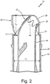
FIG. 2 is a partial cross-sectional view of the component. -
FIG. 3 is a cross-sectional view of the component in final form and installed within a larger assembly. - The present invention is directed to an additively manufactured component with integral handling protection. More specifically, the component, in an intermediate form, includes a structure attached to the component and positioned to protect a fragile feature during secondary processing, and is removed after secondary processing to produce a final component. The removable structure is additively manufactured as part of the component.
-
FIGS. 1 and2 are perspective and partial cross-sectional views, respectively, ofcomponent 10. As shown,component 10 is an element flow tube intended for use in a total air temperature (TAT) probe assembly (shown inFIG. 3 ).Component 10 is generally cylindrical, and includesmain body 12 having upstream end (top) 14 and downstream end (bottom) 16, based on the orientation ofcomponent 10 in the figures. As can be seen inFIG. 2 ,main body 12 includes inner and outerconcentric cylinders - With continued reference to
FIGS. 1 and2 ,tip 22 extends upward frominner cylinder 18 atupstream end 14 ofmain body 12.Tip 22 includescrenellations 24 which form a series of alternating peaks and valleys. In the embodiment shown,crenellations 24 are tapered with truncated, flat ends. In alternative embodiments, the shape of crenellations can be either tapered or a constant width with sharp, flat, or rounded ends. Further,tip 22 is shown withcrenellations 24 at a roughly 45° angle, but can be oriented at other angles, depending on the shape and/or air flow parameters of the TAT probe assembly. Because of its structure and position oncomponent 10,tip 22 withcrenellations 24 can be susceptible to damage during secondary processing. -
Component 10 also includesremovable collar portion 26 extending away fromupstream end 14 ofmain body 12. As can be seen inFIG. 2 ,tip 22 extends a first length L1 fromupstream end 14, whilecollar 26 extends a second, greater length L2 fromupstream end 14. Collar 26 almost fully encirclestip 22, and includes opening 28, which can accommodate specialized tools during secondary processing. In alternative embodiments, opening 28 can be smaller or larger depending on the types of tools used for assembly. If no such tools are needed,collar 26 can instead fully encircletip 22 such that opening 28 is not present. - Collar 26 is attached to
upstream end 14 ofmain body 14 by a number ofthin posts 30.Posts 30secure collar 26 tomain body 12, and also serve as the point of detachment ofcollar 26 prior to installation ofcomponent 10, as is discussed in greater detail below. In an exemplary embodiment,component 10 includes six generally evenly-spaced posts 30. Alternative embodiments can, however, generally include anywhere from three to seven posts, depending on, for example, the specific secondary processing protocol forcomponent 10. The number and spacing ofposts 30 can be optimized to balance the need for secure attachment ofcollar 26 tomain body 12, with the desire to quickly and easily removecollar 26. -
Outer cylinder 20 ofmain body 12 has a diameter D1 (FIG. 2 ), which is greater than diameter D2 (FIG. 1 ) of tip 22 (and generally inner cylinder 18). Collar 26 has a diameter D3 (FIG. 1 ) which, as shown, is roughly equivalent to D1. In alternative embodiments, however, D3 can be larger or smaller than D1, depending on design parameters and/or protection requirements. -
Component 10 can be formed using a powder bed fusion additive manufacturing technique, such as selective laser melting (SLM) in an exemplary embodiment. A digital model ofcomponent 10 withcollar 26 is inputted into an additive manufacturing apparatus such thatcollar 26 is integrally formed with the rest ofcomponent 10 to create an intermediate (i.e., pre-installation) version ofcomponent 10.Component 10 can be formed from a metallic material, such as a nickel-chromium alloy. Alternative embodiments can be formed from other metallic materials, based on, for example, material availability or the desired strength and fabricability ofcomponent 10. - After manufacturing,
component 10 can undergo one or more secondary processing steps. For example,component 10 can undergo one or more high-temperature treatments, such as an annealing process and/or a hot isostatic pressing (HIP) process to improve the mechanical properties ofcomponent 10. Any resulting surface oxidation can then be removed using a process such as chemical etching, machining, buffing, or grit blasting, to name a few, non-limiting examples.Component 10 can further be welded or brazed as it is assembled with additional subcomponents of the TAT probe assembly. During secondary processing, the configuration (e.g., shape, size, positioning, etc.) ofcollar 26 protectstip 22 withcrenellations 24 from handling damage such as dropping or denting/bending with a tool. After secondary processing and prior to installation, an operator can removecollar 26 by mechanically severing (e.g., with diagonal pliers) posts 30 at the attachment tomain body 12. Any remnants ofposts 30 onmain body 12 can be removed by sanding or trimming, or can be left in place. -
FIG. 3 is a cross-sectional view of component (element flow tube) 10 in final form and installed withinTAT probe assembly 32. In operation,tip 22 withcrenellations 24 comes into contact with airflow A and particles P, which can freeze to form ice.Crenellations 24 decrease ice accretion attip 22, which protects sensingelement 34 disposed withincomponent 10, thus allowing for more accurate measurements fromassembly 32. - Additively manufactured
component 10 has many benefits. As is discussed above, the crenellated tip is critical for proper functioning of the TAT probe assembly. Additive manufacturing allows for the creation of very precise geometries at the tip, and also allows for the formation of an integral collar to protect the tip from damage during handling and secondary processing. Because it is formed from the same metallic material as the component, the protective collar can also withstand the various thermal and chemical treatments, such that it does not need to be removed during these steps. Finally, the protective collar can fairly easily be removed for final installation. Although discussed in the context of a temperature sensing application, integral handling protection can generally be used for any application with additively manufactured components with fragile features requiring protection prior to installation or use. - The following are non-exclusive descriptions of possible embodiments of the present invention.
- A component having integral handling protection includes a main body, a fragile portion of the main body, and a removable portion of the main body positioned and configured to protect the fragile portion during handling of the component.
- The component of the preceding paragraph can optionally include, additionally and/or alternatively, any one or more of the following features, configurations and/or additional components:
In the above component, the fragile portion can include a tip extending away from an upstream end of the main body a first length, the removable portion can include a collar at least partially encircling the tip and extending from the upstream end a second length, and the second length can be greater than the first length. - In any of the above components, the main body can have a first diameter, the tip can have a second diameter, and the collar can have a third diameter.
- In any of the above components, the second diameter can be smaller than the first diameter.
- In any of the above components, the second diameter can be smaller than the third diameter.
- In any of the above components, the first diameter can be equal to the third diameter.
- In any of the above components, the tip can include crenellations forming a plurality peaks and valleys.
- In any of the above components, a plurality of posts can connect the collar to the main body.
- In any of the above components, the plurality of posts can include at least three posts.
- In any of the above components, the component can be monolithically formed from a metallic material.
- A method of protecting a fragile feature of a component during handling includes building an intermediate component in a layer-by-layer-fashion. The intermediate component includes a main body, a fragile portion of the main body, and a removable portion of the main body positioned and configured to protect the fragile portion.
- The method of the preceding paragraph can optionally include, additionally and/or alternatively, any one or more of the following features, configurations and/or additional components:
In the above method, the fragile portion can include a tip extending away from an upstream end of the main body a first length, the removable portion can include a collar at least partially encircling the tip and extending from the upstream end a second length, and the second length can be greater than the first length. - Any of the above methods can further include performing a secondary processing step on the intermediate component, and removing the collar from the main body.
- Any of the above methods can further include installing the final component into an assembly.
- In any of the above methods, the secondary processing step can be a thermal treatment.
- In any of the above methods, the secondary processing step can be an oxidation removal process selected from the group consisting of chemical etching, machining, buffing, grit blasting, and combinations thereof.
- In any of the above methods, the secondary processing step can be a welding or brazing process.
- In any of the above methods, the collar can be connected to the main body by a plurality of posts, and the removing step can include mechanically severing the plurality of posts.
- In any of the above methods, the intermediate component can be formed from a metallic material.
- In any of the above methods, the building step can be carried out using a powder bed fusion technique.
- While the invention has been described with reference to an exemplary embodiment(s), it will be understood by those skilled in the art that various changes may be made and equivalents may be substituted for elements thereof without departing from the scope of the invention. In addition, many modifications may be made to adapt a particular situation or material to the teachings of the invention without departing from the essential scope thereof. Therefore, it is intended that the invention not be limited to the particular embodiment(s) disclosed, but that the invention will include all embodiments falling within the scope of the appended claims.
Claims (15)
- A component having integral handling protection, the component comprising:a main body;a fragile portion of the main body; anda removable portion of the main body positioned and configured to protect the fragile portion during handling of the component.
- The component of claim 1, wherein:the fragile portion comprises a tip extending away from an upstream end of the main body a first length;the removable portion comprises a collar at least partially encircling the tip and extending from the upstream end a second length; andthe second length is greater than the first length.
- The component of claim 2, wherein the main body has a first diameter, the tip has a second diameter, and the collar has a third diameter.
- The component of claim 3, wherein the second diameter is smaller than the first diameter.
- The component of claim 4, wherein the second diameter is smaller than the third diameter, and / or
wherein the first diameter is equal to the third diameter. - The component of any of claims 2 to 5, wherein the tip includes crenellations forming a plurality peaks and valleys.
- The component of any of claims 2 to 6, wherein a plurality of posts connect the collar to the main body,
wherein, optionally, the plurality of posts comprises at least three posts. - The component of any of claims 2 to 7, wherein the component is monolithically formed from a metallic material.
- A method of protecting a fragile feature of a component during handling, the method comprising: building, in a layer-by-layer fashion, an intermediate component comprising:a main body;a fragile portion of the main body; anda removable portion of the main body and positioned and configured to protect the fragile portion.
- The method of claim 9, wherein:the fragile portion comprises a tip extending away from the main body a first length;the removable portion comprises a collar at least partially encircling the tip and extending from the upstream end of the main body a second length; andthe second length is greater than the first length.
- The method of claim 10 and further comprising: performing a secondary processing step on the intermediate component, and removing the collar from the main body.
- The method of claim 11 and further comprising: installing the component into an assembly.
- The method of claim 11 or 12, wherein the secondary processing step is a thermal treatment, and / or
wherein the secondary processing step is an oxidation removal process selected from the group consisting of chemical etching, machining, buffing, grit blasting, and combinations thereof, and / or
wherein the secondary processing step is a welding or brazing process. - The method of any of claims 10 to 13, wherein the collar is connected to the main body by a plurality of posts, and wherein the removing step comprises mechanically severing the plurality of posts.
- The method of any of claims 10 to 14, wherein the intermediate component is formed from a metallic material, and/or wherein the building step is carried out using a powder bed fusion technique.
Applications Claiming Priority (1)
| Application Number | Priority Date | Filing Date | Title |
|---|---|---|---|
| US16/000,412 US10889060B2 (en) | 2018-06-05 | 2018-06-05 | Additively manufactured integrated handling protection |
Publications (1)
| Publication Number | Publication Date |
|---|---|
| EP3578281A1 true EP3578281A1 (en) | 2019-12-11 |
Family
ID=66998057
Family Applications (1)
| Application Number | Title | Priority Date | Filing Date |
|---|---|---|---|
| EP19178115.2A Withdrawn EP3578281A1 (en) | 2018-06-05 | 2019-06-04 | Additively manufactured integrated handling protection |
Country Status (4)
| Country | Link |
|---|---|
| US (1) | US10889060B2 (en) |
| EP (1) | EP3578281A1 (en) |
| BR (1) | BR102019009211A2 (en) |
| CA (1) | CA3044871A1 (en) |
Citations (4)
| Publication number | Priority date | Publication date | Assignee | Title |
|---|---|---|---|---|
| US6186980B1 (en) * | 1999-10-07 | 2001-02-13 | Sanofi-Synthelabo | Single-use device for injection |
| DE102007033434A1 (en) * | 2007-07-18 | 2009-01-22 | Voxeljet Technology Gmbh | Method for producing three-dimensional components |
| DE102007048385B3 (en) * | 2007-10-09 | 2009-01-29 | Fraunhofer-Gesellschaft zur Förderung der angewandten Forschung e.V. | Production of components using generative processes, especially fused deposition modeling, comprises forming grid around component which is gripped to manipulate component, without direct contact with component itself |
| EP3147049A1 (en) * | 2015-09-28 | 2017-03-29 | United Technologies Corporation | Duct with additive manufactured seal and related method |
Family Cites Families (3)
| Publication number | Priority date | Publication date | Assignee | Title |
|---|---|---|---|---|
| JP4300285B2 (en) * | 2000-01-07 | 2009-07-22 | グラクソ グループ リミテッド | Infusion device for single doses of liquids, especially pharmaceutical liquids |
| US8077894B2 (en) | 2007-01-22 | 2011-12-13 | Siemens Hearing Instruments, Inc. | Feature protection for stereo lithographic manufacturing processes |
| US8221858B2 (en) | 2010-07-22 | 2012-07-17 | Stratasys, Inc. | Three-dimensional parts having porous protective structures |
-
2018
- 2018-06-05 US US16/000,412 patent/US10889060B2/en not_active Expired - Fee Related
-
2019
- 2019-05-06 BR BR102019009211A patent/BR102019009211A2/en not_active IP Right Cessation
- 2019-05-30 CA CA3044871A patent/CA3044871A1/en not_active Abandoned
- 2019-06-04 EP EP19178115.2A patent/EP3578281A1/en not_active Withdrawn
Patent Citations (4)
| Publication number | Priority date | Publication date | Assignee | Title |
|---|---|---|---|---|
| US6186980B1 (en) * | 1999-10-07 | 2001-02-13 | Sanofi-Synthelabo | Single-use device for injection |
| DE102007033434A1 (en) * | 2007-07-18 | 2009-01-22 | Voxeljet Technology Gmbh | Method for producing three-dimensional components |
| DE102007048385B3 (en) * | 2007-10-09 | 2009-01-29 | Fraunhofer-Gesellschaft zur Förderung der angewandten Forschung e.V. | Production of components using generative processes, especially fused deposition modeling, comprises forming grid around component which is gripped to manipulate component, without direct contact with component itself |
| EP3147049A1 (en) * | 2015-09-28 | 2017-03-29 | United Technologies Corporation | Duct with additive manufactured seal and related method |
Also Published As
| Publication number | Publication date |
|---|---|
| US20190366642A1 (en) | 2019-12-05 |
| US10889060B2 (en) | 2021-01-12 |
| BR102019009211A2 (en) | 2019-12-10 |
| CA3044871A1 (en) | 2019-12-05 |
Similar Documents
| Publication | Publication Date | Title |
|---|---|---|
| US10272461B2 (en) | Method for masking cooling passages | |
| US8978249B2 (en) | Methods for repairing a gas turbine component | |
| EP2223753B1 (en) | Process and refractory metal core for creating varying thickness microcircuits for turbine engine components | |
| EP2781872B1 (en) | Heat exchanger design and fabrication | |
| EP3168418B1 (en) | Cooling article and method of forming a cooling article | |
| CN108979733B (en) | Component for use in a hot gas path of an industrial machine | |
| EP3168419B1 (en) | Article and method of forming an article | |
| EP2359972A2 (en) | Method of creating an airfoil trench and a plurality of cooling holes within the trench | |
| CN106194273B (en) | Articles, components and methods of forming articles | |
| EP1604770A2 (en) | Method of replacing damaged aerofoil | |
| EP2113634B1 (en) | Method of repairing a gas turbine engine case with replaced flange using cold metal transfer | |
| CN104689958A (en) | Coating methods and a coated substrate | |
| US20140102684A1 (en) | Hot gas path component cooling film hole plateau | |
| US10889060B2 (en) | Additively manufactured integrated handling protection | |
| CN101827682A (en) | Diffusion bonding | |
| EP2621038A2 (en) | Method of producing an electrode support using brazing | |
| HU231277B1 (en) | Plug equipped with a layer soluble in water for the protection of bores and holes in components during the coating process | |
| CN113492531A (en) | Cantilevered mask for openings in an additive manufactured part | |
| US11414195B2 (en) | Surface modified heater assembly | |
| EP2626636A2 (en) | Fuel nozzle end cover, fuel nozzle, and process of fabricating a fuel nozzle end cover | |
| CN106457487A (en) | Method for repairing airfoil, and cooling collar | |
| EP1958702B1 (en) | Masking system using temperature-resistant hook and loop fasteners | |
| JP2021161537A (en) | Cantilevered mask for openings in additively manufactured part | |
| US7387817B2 (en) | Method for masking a workpiece before encapsulation in a casting block | |
| JP7573484B2 (en) | Method for manufacturing additive objects |
Legal Events
| Date | Code | Title | Description |
|---|---|---|---|
| PUAI | Public reference made under article 153(3) epc to a published international application that has entered the european phase |
Free format text: ORIGINAL CODE: 0009012 |
|
| STAA | Information on the status of an ep patent application or granted ep patent |
Free format text: STATUS: THE APPLICATION HAS BEEN PUBLISHED |
|
| AK | Designated contracting states |
Kind code of ref document: A1 Designated state(s): AL AT BE BG CH CY CZ DE DK EE ES FI FR GB GR HR HU IE IS IT LI LT LU LV MC MK MT NL NO PL PT RO RS SE SI SK SM TR |
|
| AX | Request for extension of the european patent |
Extension state: BA ME |
|
| STAA | Information on the status of an ep patent application or granted ep patent |
Free format text: STATUS: REQUEST FOR EXAMINATION WAS MADE |
|
| 17P | Request for examination filed |
Effective date: 20200610 |
|
| RBV | Designated contracting states (corrected) |
Designated state(s): AL AT BE BG CH CY CZ DE DK EE ES FI FR GB GR HR HU IE IS IT LI LT LU LV MC MK MT NL NO PL PT RO RS SE SI SK SM TR |
|
| GRAP | Despatch of communication of intention to grant a patent |
Free format text: ORIGINAL CODE: EPIDOSNIGR1 |
|
| STAA | Information on the status of an ep patent application or granted ep patent |
Free format text: STATUS: GRANT OF PATENT IS INTENDED |
|
| INTG | Intention to grant announced |
Effective date: 20201023 |
|
| STAA | Information on the status of an ep patent application or granted ep patent |
Free format text: STATUS: THE APPLICATION IS DEEMED TO BE WITHDRAWN |
|
| 18D | Application deemed to be withdrawn |
Effective date: 20210303 |