EP0850718B1 - Process for linear friction welding - Google Patents
Process for linear friction welding Download PDFInfo
- Publication number
- EP0850718B1 EP0850718B1 EP97310560A EP97310560A EP0850718B1 EP 0850718 B1 EP0850718 B1 EP 0850718B1 EP 97310560 A EP97310560 A EP 97310560A EP 97310560 A EP97310560 A EP 97310560A EP 0850718 B1 EP0850718 B1 EP 0850718B1
- Authority
- EP
- European Patent Office
- Prior art keywords
- collar
- major
- linear friction
- friction welding
- interfaced
- Prior art date
- Legal status (The legal status is an assumption and is not a legal conclusion. Google has not performed a legal analysis and makes no representation as to the accuracy of the status listed.)
- Expired - Lifetime
Links
Images


Classifications
-
- B—PERFORMING OPERATIONS; TRANSPORTING
- B23—MACHINE TOOLS; METAL-WORKING NOT OTHERWISE PROVIDED FOR
- B23K—SOLDERING OR UNSOLDERING; WELDING; CLADDING OR PLATING BY SOLDERING OR WELDING; CUTTING BY APPLYING HEAT LOCALLY, e.g. FLAME CUTTING; WORKING BY LASER BEAM
- B23K20/00—Non-electric welding by applying impact or other pressure, with or without the application of heat, e.g. cladding or plating
- B23K20/12—Non-electric welding by applying impact or other pressure, with or without the application of heat, e.g. cladding or plating the heat being generated by friction; Friction welding
- B23K20/129—Non-electric welding by applying impact or other pressure, with or without the application of heat, e.g. cladding or plating the heat being generated by friction; Friction welding specially adapted for particular articles or workpieces
-
- B—PERFORMING OPERATIONS; TRANSPORTING
- B23—MACHINE TOOLS; METAL-WORKING NOT OTHERWISE PROVIDED FOR
- B23K—SOLDERING OR UNSOLDERING; WELDING; CLADDING OR PLATING BY SOLDERING OR WELDING; CUTTING BY APPLYING HEAT LOCALLY, e.g. FLAME CUTTING; WORKING BY LASER BEAM
- B23K20/00—Non-electric welding by applying impact or other pressure, with or without the application of heat, e.g. cladding or plating
- B23K20/12—Non-electric welding by applying impact or other pressure, with or without the application of heat, e.g. cladding or plating the heat being generated by friction; Friction welding
- B23K20/1205—Non-electric welding by applying impact or other pressure, with or without the application of heat, e.g. cladding or plating the heat being generated by friction; Friction welding using translation movement
-
- F—MECHANICAL ENGINEERING; LIGHTING; HEATING; WEAPONS; BLASTING
- F01—MACHINES OR ENGINES IN GENERAL; ENGINE PLANTS IN GENERAL; STEAM ENGINES
- F01D—NON-POSITIVE DISPLACEMENT MACHINES OR ENGINES, e.g. STEAM TURBINES
- F01D5/00—Blades; Blade-carrying members; Heating, heat-insulating, cooling or antivibration means on the blades or the members
- F01D5/30—Fixing blades to rotors; Blade roots ; Blade spacers
- F01D5/3061—Fixing blades to rotors; Blade roots ; Blade spacers by welding, brazing
-
- B—PERFORMING OPERATIONS; TRANSPORTING
- B23—MACHINE TOOLS; METAL-WORKING NOT OTHERWISE PROVIDED FOR
- B23K—SOLDERING OR UNSOLDERING; WELDING; CLADDING OR PLATING BY SOLDERING OR WELDING; CUTTING BY APPLYING HEAT LOCALLY, e.g. FLAME CUTTING; WORKING BY LASER BEAM
- B23K2101/00—Articles made by soldering, welding or cutting
- B23K2101/001—Turbines
-
- F—MECHANICAL ENGINEERING; LIGHTING; HEATING; WEAPONS; BLASTING
- F05—INDEXING SCHEMES RELATING TO ENGINES OR PUMPS IN VARIOUS SUBCLASSES OF CLASSES F01-F04
- F05D—INDEXING SCHEME FOR ASPECTS RELATING TO NON-POSITIVE-DISPLACEMENT MACHINES OR ENGINES, GAS-TURBINES OR JET-PROPULSION PLANTS
- F05D2230/00—Manufacture
- F05D2230/20—Manufacture essentially without removing material
- F05D2230/23—Manufacture essentially without removing material by permanently joining parts together
Definitions
- This invention relates to linear friction welding.
- structures may be bonded together by means of linear friction welding.
- a surface on one of the structures is contacted (interfaced) to a surface on the other structure.
- the interfacing surfaces typically have complimentary features, i.e. similar lengths and similar widths.
- the two parts are rubbed together, in a back and forth, somewhat linear type oscillatory manner.
- the axis of the oscillation is typically roughly aligned with the longitudinal (lengthwise) axis of the interface, i.e. end to end.
- compressive force is applied to place the interface under high pressure.
- frictional heat is generated and material from each part changes to a molten or preferably to a plastic state.
- flash flow Some of this material flows out from between the parts (flash flow), resulting in gradual decrease in the thickness, i.e. the dimension in the direction in which pressure is applied (the dimension perpendicular to the interface) of the parts.
- flash flow ceases, and at the interface, the remaining plastic state material of each part cools and changes back to solid state, forming bonds therein and bonding the two parts together.
- the bond is usually incomplete, i.e. defective, at the ends of the interface.
- the nature of the defect is that of a void, or notch. It occurs, in part, because the ends of the interface, roughly on the axis of oscillation, are alternately exposed to ambient during each oscillation cycle. While exposed, the end is not rubbed and therefore not frictionally heated. Thus, as a result of the alternating exposure, the ends are only alternately heated and the temperature of the ends does not get high enough to produce complete bonding.
- part geometries can be oversized so that the defects which form are located outside the outline of the final product. The defects are then removed as the product is machined down to its final shape. However, in repair situations, a damaged portion is removed, but the remaining portion is already at its final shape and dimension, and therefore, an oversized geometry is not a viable alternative.
- the damaged portion of a blade under repair is removed, e.g., by removing a longitudinal section, and flanges, or collars, are provided around the edges of the remaining portion.
- a pair of jaws grip the remaining (undamaged) portion, (having, as its final shape, the final shape of the repaired part), and its associated flange to secure each in place for linear friction welding.
- the undamaged portion is already joined to the IBR (as by linear friction welding), the undamaged portion is not rigid enough, side to side, and too highly cantilevered to undergo linear friction welding without the support of the jaws or similar tooling.
- Similar flanges and jaws are also provided to grip a replacement portion, also having as its final shape, the final shape of the repaired part, to linear friction weld it to the undamaged portion.
- the flanges around each portion prevent the blade edges of the other portion from being alternately exposed to ambient; thus sufficient heat is generated to achieve effective bonding. Defects may be formed in the flange region, because the flanges may be alternately exposed to ambient, but the flanges are subsequently machined away, along with such defects.
- the jaws generally cannot conform exactly to the shape of an individual blade, because the shapes of the blades vary somewhat from one another, due to normal manufacturing inaccuracies, and therefore, the jaws may cause physical damage to any particular blade when they grip it tightly.
- high performance blades often comprise titanium, a relatively soft metal which is relatively easily marred on its surface. Such marring is highly undesirable because it adversely affects the aerodynamic performance of the blades.
- the jaws typically do not have the same material composition as the blades, and consequently, they can leave residual chemical deposits which thereby contaminate the surface finish. The surface finish is so critical in some applications that during fabrication, gloves are often worn when handling the blades in order to prevent contamination of the blade surface finish.
- the replacement portion is almost certain to be significantly damaged because it is solely supported by jaws gripping its finished airfoil. Unlike the remaining portion, the replacement portion is not integral to a larger structure, such as the blade disk, which provides support. Thus, the jaws grip the finished airfoil securely enough to withstand tens of thousands of pounds of pressure, and therefore, almost certainly inflict deep imprints in the airfoil.
- flanges tend to be large, contributing as much, or more, surface area to the interface, as that of the blade. While this may help prevent defects from forming in the blade edges, it requires excessive process input energy to overcome the friction contributed by the flanges alone, and subjects the flanges to tremendous loads during linear friction welding, making them extremely difficult to hold securely, especially in view of the fact that the same pair of jaws has to grip the both the flanges and the blade.
- Prior art flanges also have sharp, orthogonal edges, making the flanges more susceptible to stress and cracking during linear friction welding.
- EP-A-0 669 183 discloses a friction welding process for joining parts of a rotor blade.
- the linear friction welding process of the present invention provides two members which are to be joined together into a final product, where each of the members has a major outer surface and a surface to be interfaced, and where one of the two members is a stub which is surrounded, at least in part, on its outer major surface by a collar.
- the stub is generally restrained without substantial restraining contact on its outer major surface by tooling. Thereafter, pressure and relative movement are applied between said members to linear friction weld the members together.
- the stub member should generally be rigid enough to undergo linear friction welding without any substantial restraining support of the jaws or similar tooling, the stub preferably having a radial thickness which is less than about three times its width, preferably less than about one inch (2.54 cm), more preferably less than its width.
- the collar which reduces alternating exposure to ambient of the other member's interface surface, may comprise a band having curved major inner and outer (lateral) surfaces.
- the inner and outer major collar surfaces may be generally parallel to each other making the collar generally uniform in width.
- the collar may further comprise a base upon which the band is upstanding.
- the surfaces to be interfaced on the stub and the collar are preferably substantially coplanar with each other.
- the other member's interface surface may be oversized, integrally or with a collar, preferably making it complementary to that of the stub, to reduce alternating exposure to ambient of the stub's interface surface.
- a preferred collar comprises major inner and outer lateral surfaces, the major inner surface surrounding a portion of a major outer (lateral) surface of a member to be linear friction welded.
- the member has a surface to be interfaced for linear friction welding with a complementary member, the radially outer surface of the collar providing an extension to the area of the surface of the member to be interfaced.
- the outer lateral surface may be curved in order to prevent stress and cracking of the collar during linear friction welding.
- the inner and outer lateral collar surfaces may be generally parallel to each other, making the area of the outer radial surface of the collar small, and somewhat uniform in width, so that less process input energy is needed to overcome the friction contributed by the collars, and so that the collars experience smaller loads during linear friction welding, making them easier to secure.
- the collar may have a radial thickness which is less than one inch (2.54 cm).
- the area of the radial outer surface of the collar is typically less than that of the member's surface to be interfaced, preferably less than one half that of the member.
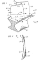
- the present invention is disclosed with respect to various embodiments for use with a first stage integrally bladed fan rotor of the type illustrated in FIG. 1.
- an integrally bladed fan rotor 20 has a disk 22 with a platform 24 having a radially outer surface 26.
- Blades (airfoils) 28 extend from the top, or radially outer surface 26 of the disk 22. It will be understood that the blades 28 are two of a plurality of such blades attached to the disk 22.
- Each of the blades 28 has a base 30 and a tip 32, as well as a leading edge 33 and a trailing edge 34, relative to a gas flow path 35.
- One of the blades 28 has a damaged portion 38.
- the blade 28 has an intricately twisted and bent shape, which provides the blade with the desired aerodynamic properties.
- One side (suction side) 36 of the blade is convex and the other (pressure side) 37 is concave.
- pressure side is concave.
- each of the plurality of blades has exactly the same shape, but realistically, the shapes of the blades vary somewhat from one another, due to normal manufacturing inaccuracies.
- the blade 28 is typically comprised of a material which is relatively light weight yet sufficiently strong mechanically, such as a titanium alloy. Nevertheless, the blade 28 must be handled carefully during fabrication and repair, to insure that the blade is not distorted or damaged. Furthermore, to prevent residual chemical deposits and surface finish contamination any metal tools which contact the blade 28 preferably comprise the same, or similar, material to that of the blade.
- the pressure side 37 of the blade 28 is cantilevered toward the surface 26 of the platform 24. While the cantilevering is ideally the same for each of the blades, realistically, it too varies from blade to blade.
- the major portion of the blade 28 located above the dotted line 41 is removed.
- a stub portion 42 of the blade i.e. a portion which is rigid enough to undergo linear friction welding without any substantial restraining support of the jaws or similar tooling.
- the stub typically has a radial thickness 43, or height, having a magnitude which is less than about three times that of its width 31.
- the stub radial thickness 43 is preferably about one inch (2.54 cm) or less, more preferably less than about its width 31.
- the stub 42 preferably extends from the leading edge 33 to the trailing edge 34, and the radial thickness 43, or height, is preferably generally uniform.
- the stub 42 comprises a radially outer surface 44, which constitutes a portion of a surface to be interfaced, whereupon linear friction welding of an extension member to form a final product is to be initiated, and a major outer (lateral) surface 45, which is preferably generally coextensive with the outer lateral surface of the final product, comprising the pressure and suction side surfaces 36, 37 (FIGS. 1, 2) and the leading and trailing edges 33, 34.
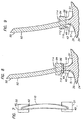
- Collars 46, 47 are provided at the leading and trailing edges 33, 34 of the stub 42.
- each band 48, 49 is generally V-shaped, having a bifurcating end 52, 53, a major inner (lateral) surface 54, 55, a major outer (lateral) surface 56, 57, and a radially outer surface 58, 59.
- the inner surfaces are preferably adapted to make substantially uniform contact with the respective edge 33, 34 and the sides 36, 37 (FIGS. 1, 2) of the stub 42.
- the radially outer surfaces 58, 59 constitute the other portions of the surface to be interfaced for linear friction welding, and are preferably substantially flush, or substantially coplanar, with the radially outer surface 44 of the stub 42, i.e. generally at the same height as each other relative to the platform surface 26.
- the major outer surfaces 56, 57 are curved at the bifurcating ends 52, 53, to eliminate sharp corners that could otherwise develop stress during linear friction welding and ultimately crack.
- the geometry of the bands 48, 49 should be suitable to reduce or eliminate the alternating exposure of the edges on an extension blade member which is to be linear friction welded to the stub, so that the temperature of the edges on the extension member gets high enough to achieve complete bonding, i.e. no defects at the edges.
- the bands 48, 49 preferably provide circumferential, (lateral, pressure side to suction side) support for the stub 42, to keep the cantilevered stub from bending toward the platform 24 surface 26 during linear friction welding.
- the magnitude of the load experienced by the bands during linear friction welding is proportional to the magnitude of the area of the radially outer surfaces 58, 59. Higher loads make it more difficult to hold the band in place.
- the outer lateral surfaces 56, 57 are generally parallel to the inner lateral surfaces 54, 55, such that the bands 48, 49 are generally uniform in width 60, 61 and generally conform to the major outer surface 45 of the stub 42. This makes the area of the radial outer surfaces 58, 59 of the bands small, so that less process input energy is needed to overcome the friction contributed by the bands, and so that the collars experience smaller loads during linear friction welding, making them easier to secure.
- the total area of the radial outer surfaces 58, 59 is typically less than that of the radially outer surface 44 of the stub 42, usually less than that of the portion of the radially outer surface 44 which is partially enclosed by the bands, preferably less than one half that of the stub 42 radially outer surface 44, more preferably less than one quarter that of the stub 42 radially outer surface 44.
- the bands 48, 49 have radial thicknesses 62, 64 (heights) which will gradually decrease during LFW.
- the initial radial thicknesses 62, 64 are preferably at least as great as the expected decrease, in order to prevent the linear friction welding interface from reaching the radially outer surfaces 66, 68 of the bases 50, 51,.
- the thicknesses 62, 64 are preferably not so large as to make the bands 48, 49 susceptible to breaking or bending during linear friction welding.
- the radial thickness 62, 64 is about 0.175 inches (4.5 mm) and the expected decrease in the thickness 62, 64, is about 0.075 inches (1.9 mm), so that the radial thickness is on the order of about 0.100 inches (2.5 mm) greater than the expected decrease in the thickness.
- Each band 48, 49 is supported by, i.e. upstanding or extending from, a radially outer surface 66, 68 of its respective base 50, 51.
- the bases 50, 51 have somewhat rectangular plate-like geometry and V-shaped slots 69, 70 for receiving the stub 42.
- the V-shaped slots 69, 70 are large enough to prevent contact between the stub 42 and the bases 50, 51.
- the bases 50, 51 further comprise radially inner surfaces 71, 72 adapted (contoured) to rest on the radially outer surface 26 of the platform 24.
- Each base 50, 51 is preferably held in place by means of associated tooling 73, 74 (FIG.
- the tooling 73, 74 (FIG. 6) is rigidly connected to fixturing 79, 80 (FIG. 6) which hold the disk 22.
- the radially inner surfaces 71, 72 are preferably notched, or scalloped, 81, 82 to provide clearances 83, 84 with respect to the platform 24, to permit the fixturing 79, 80 (FIG. 6) access to the platform 24.
- the bands 48, 49 may be joined to their respective bases 50, 51 by such means as brazing, or, to reduce cost, integrally fabricated as one piece, preferably in two steps.
- a rough machined version of the collar is produced by such means as wire electro discharge machining (wire EDM, which requires a computer and a computer model of the collar).
- the rough version is subsequently precision machined, for example by milling, in order to obtain the best possible fit for the particular blade.
- casting, machining, forging, rolling, and stamping, and combinations thereof may also be used.
- the two step process is preferred because each of the plurality of the blades has a somewhat different shape and orientation, although some applications may not require such precision.
- the collar preferably comprises a relatively rigid material, similar in composition to that of the stub, which may include but is not limited to titanium alloys and nickel alloys, thereby allowing the collars to secure the stub blade portion 42 without causing physical or chemical damage. It will be obvious that if a compliant material is used, or contact with the blade is not desired, the precision machining step may not be necessary.
- an extension member 90 comprises a blade 92 which has as its final shape, the final shape of the repaired blade, a flange 94 and an end 96, which are all integral to the extension member 90.
- the flange 94 provides the means for holding the extension member 90 and the end 96 is joined to the stub 42.
- the flange 94 has a radially outer surface 98 which receives the linear friction welding pressure force, a pair 100 of opposite circumferential surfaces, a pair 102 of opposite longitudinal surfaces which preferably receive the linear friction welding oscillation forces, and a radially inner surface 104, all of which are substantially orthogonal to each other.
- the end 96 has a radially inner surface 108 that is complementarily shaped, similar to, but not necessarily exactly the same as, the aggregation of the radially outer surfaces 44, 58, 59 of the stub 42 and bands 48, 49 (see FIG. 7). If the surfaces are not complementary, the linear friction welding oscillation can become obstructed as the thicknesses of the parts decrease, potentially disturbing the interface. To provide the complementary shape, the end 96 is preferably integrally oversized, although collars could be used instead.
- the end 96 has a radial thickness 110 which should be large enough in magnitude to prevent the linear friction welding interface from reaching the radially inner surface 104 of the flange 94, but not so large as to make the end 96 susceptible to breaking or bending during linear friction welding.
- the radial thickness 110 is of the order of about 0.100 inches (2.5 mm) greater than the expected decrease in thickness 110 due to linear friction welding.
- the extension member 90 in preparation for linear friction welding, the extension member 90 is brought into contact with the stub 42 and bands 48 (FIGS. 3, 4, 6), 49.
- tooling does not restrain the members on any finished surfaces, thus, there is no risk of physical or chemical damage to the blade from such tooling.
- the collars are smaller yet easier to hold than those used in the prior art approach. All the material between dotted lines 112 gradually changes to a plastic state and flows out from between the parts (flash flow), thereby reducing the radial thickness of the extension member 90, the stub 42 and the bands 48(FIGS. 3, 4, 6), 49.
- the collars prevent the edges of the extension member from being alternately exposed to ambient.
- the oversized end 96 of the extension member 90 prevents alternating exposure of the stub edges 33, 34.
- Dotted lines 114 indicate the final shape of the oversized extension member 90.
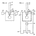
- a second embodiment for a trailing edge collar 118 comprises only a band 120, i.e. no base.
- the band 120 is preferably comprised of a cold formable material.
- the band 120 is secured to and forced into conformance with the edge 34 of the stub 42 by a set of jaws 122 flexibly, movably integrated into tooling 124.
- the tooling 124 further comprises an actuator 126 for applying force on the jaws 122 to force the jaws into closer proximity with each other, and thereby force the band 120 into conformance with the edge 34.
- the tooling is attached to the fixture 80 (FIG. 6) holding the disc 22 (FIG. 6).
- the band 120 has a radial thickness which is large enough in magnitude to prevent the linear friction welding interface from reaching the surface of the tooling 124, but not so large as to make the band 120 susceptible to breaking or bending during linear friction welding.
- another collar with tooling is similarly provided at the leading edge 33 (FIGS. 1-3). As with the first embodiment, this embodiment does not need to restrain the members on any finished surfaces with tooling and thus, it eliminates the risk of physical or chemical damage to the blade from such tooling.
- means 130 for actuating the jaws 132 are a set of clamps each having two ends 134, 136, and rotatably connected at a pivot 138.
- the clamps may be forced apart at one 136 of their ends by a spreader 140, which causes the other 134 of the ends to pivot toward each other, and thereby forcing the jaws 132, which are similar to the jaws 122 illustrated and described with respect to FIG. 10, into closer proximity with each other.
- the alternate tooling is attached to the fixture 80 (FIG. 6) holding the disc 22 (FIG. 6).
- Another collar with tooling (not shown) is similarly provided at the leading edge 33 (FIGS. 1-3).
- the present invention discloses the collar of the present invention in contact with the stub and resting on the radially outer surface of the platform, the present invention is not so limited. So long as the collar is in the proximity of the stub and secured, the collar need not contact the stub; plastic state material from the interface may fill and seal small gaps between the collar and the stub.
- the collar may possibly be positioned off the surface of the platform. This possibility may be particularly suited to situations where the blade portion is more than a stub. However, because of the large pressure forces associated with linear friction welding, some radial support for the collar may be necessary.
- the present invention may be used with almost any size blade portion on the disc and any extension blade portion, depending on the application and the available tooling.
- the stub need not have uniform height.
- the extension member may be a replacement portion but is not so limited.
- the present invention may also be used, where in an OEM situation it is not possible to provide an oversized elevated surface on the rotor disc for the initial blade.
Landscapes
- Engineering & Computer Science (AREA)
- Mechanical Engineering (AREA)
- General Engineering & Computer Science (AREA)
- Pressure Welding/Diffusion-Bonding (AREA)
Description
- This invention relates to linear friction welding.
- As known in the art, structures may be bonded together by means of linear friction welding. In such a process, a surface on one of the structures is contacted (interfaced) to a surface on the other structure. The interfacing surfaces typically have complimentary features, i.e. similar lengths and similar widths. The two parts are rubbed together, in a back and forth, somewhat linear type oscillatory manner. The axis of the oscillation is typically roughly aligned with the longitudinal (lengthwise) axis of the interface, i.e. end to end. As the parts are rubbed, compressive force is applied to place the interface under high pressure. At the interface, frictional heat is generated and material from each part changes to a molten or preferably to a plastic state. Some of this material flows out from between the parts (flash flow), resulting in gradual decrease in the thickness, i.e. the dimension in the direction in which pressure is applied (the dimension perpendicular to the interface) of the parts. When the process is terminated, flash flow ceases, and at the interface, the remaining plastic state material of each part cools and changes back to solid state, forming bonds therein and bonding the two parts together.
- However, a problem exists with this process in that the bond is usually incomplete, i.e. defective, at the ends of the interface. The nature of the defect is that of a void, or notch. It occurs, in part, because the ends of the interface, roughly on the axis of oscillation, are alternately exposed to ambient during each oscillation cycle. While exposed, the end is not rubbed and therefore not frictionally heated. Thus, as a result of the alternating exposure, the ends are only alternately heated and the temperature of the ends does not get high enough to produce complete bonding.
- Efforts have focused on developing processes which insure that the defect does not form within the outline of the final shape of the product. In the fabrication of original equipment, part geometries can be oversized so that the defects which form are located outside the outline of the final product. The defects are then removed as the product is machined down to its final shape. However, in repair situations, a damaged portion is removed, but the remaining portion is already at its final shape and dimension, and therefore, an oversized geometry is not a viable alternative.
- One of the numerous applications for linear friction welding is that of attaching blades (airfoils) to a rotor and thereby forming an integrally bladed rotor (IBR). In such an application, a base surface on the blade is interfaced to a slightly elevated surface on the rotor. However, without preventative measures, the bond risks being defective at the blade edges, because the blade edges are situated at the ends of the interface, roughly on the oscillation axis, and therefore, the blade edges are alternately exposed to ambient and only alternately heated during oscillation. As a result, the edge temperature does not get high enough to produce complete, adequate bonding. Although the defect may not constitute a crack per se, it could mature into such during engine operation, and thus, its presence in an IBR is unacceptable.
- In the prior art approach for preventing defects at the edges for IBR repairs, the damaged portion of a blade under repair is removed, e.g., by removing a longitudinal section, and flanges, or collars, are provided around the edges of the remaining portion. A pair of jaws grip the remaining (undamaged) portion, (having, as its final shape, the final shape of the repaired part), and its associated flange to secure each in place for linear friction welding. Although the undamaged portion is already joined to the IBR (as by linear friction welding), the undamaged portion is not rigid enough, side to side, and too highly cantilevered to undergo linear friction welding without the support of the jaws or similar tooling. Similar flanges and jaws are also provided to grip a replacement portion, also having as its final shape, the final shape of the repaired part, to linear friction weld it to the undamaged portion. The flanges around each portion prevent the blade edges of the other portion from being alternately exposed to ambient; thus sufficient heat is generated to achieve effective bonding. Defects may be formed in the flange region, because the flanges may be alternately exposed to ambient, but the flanges are subsequently machined away, along with such defects.
- However, with this prior art approach, it is difficult for the jaws to securely hold the blades without causing damage to the finished shapes. First, the jaws generally cannot conform exactly to the shape of an individual blade, because the shapes of the blades vary somewhat from one another, due to normal manufacturing inaccuracies, and therefore, the jaws may cause physical damage to any particular blade when they grip it tightly. Further, high performance blades often comprise titanium, a relatively soft metal which is relatively easily marred on its surface. Such marring is highly undesirable because it adversely affects the aerodynamic performance of the blades. Still further, the jaws typically do not have the same material composition as the blades, and consequently, they can leave residual chemical deposits which thereby contaminate the surface finish. The surface finish is so critical in some applications that during fabrication, gloves are often worn when handling the blades in order to prevent contamination of the blade surface finish.
- In addition, the replacement portion is almost certain to be significantly damaged because it is solely supported by jaws gripping its finished airfoil. Unlike the remaining portion, the replacement portion is not integral to a larger structure, such as the blade disk, which provides support. Thus, the jaws grip the finished airfoil securely enough to withstand tens of thousands of pounds of pressure, and therefore, almost certainly inflict deep imprints in the airfoil.
- Another problem with prior art approaches is that the flanges tend to be large, contributing as much, or more, surface area to the interface, as that of the blade. While this may help prevent defects from forming in the blade edges, it requires excessive process input energy to overcome the friction contributed by the flanges alone, and subjects the flanges to tremendous loads during linear friction welding, making them extremely difficult to hold securely, especially in view of the fact that the same pair of jaws has to grip the both the flanges and the blade. Prior art flanges also have sharp, orthogonal edges, making the flanges more susceptible to stress and cracking during linear friction welding.
- EP-A-0 669 183 discloses a friction welding process for joining parts of a rotor blade.
- According to the invention there is provided a combination as claimed in claim 1 and a process as claimed in claim 6.
- The linear friction welding process of the present invention provides two members which are to be joined together into a final product, where each of the members has a major outer surface and a surface to be interfaced, and where one of the two members is a stub which is surrounded, at least in part, on its outer major surface by a collar. The stub is generally restrained without substantial restraining contact on its outer major surface by tooling. Thereafter, pressure and relative movement are applied between said members to linear friction weld the members together.
- Such a process eliminates the need to use tooling to grip any surfaces of the final part shape, thus eliminating the risk that tooling will cause physical or chemical damage to the final shape. At least a portion of the major outer surface of the stub may be generally coextensive with that of the final product. The stub member should generally be rigid enough to undergo linear friction welding without any substantial restraining support of the jaws or similar tooling, the stub preferably having a radial thickness which is less than about three times its width, preferably less than about one inch (2.54 cm), more preferably less than its width. The collar, which reduces alternating exposure to ambient of the other member's interface surface, may comprise a band having curved major inner and outer (lateral) surfaces. The inner and outer major collar surfaces may be generally parallel to each other making the collar generally uniform in width. The collar may further comprise a base upon which the band is upstanding. The surfaces to be interfaced on the stub and the collar are preferably substantially coplanar with each other. The other member's interface surface may be oversized, integrally or with a collar, preferably making it complementary to that of the stub, to reduce alternating exposure to ambient of the stub's interface surface.
- A preferred collar comprises major inner and outer lateral surfaces, the major inner surface surrounding a portion of a major outer (lateral) surface of a member to be linear friction welded. The member has a surface to be interfaced for linear friction welding with a complementary member, the radially outer surface of the collar providing an extension to the area of the surface of the member to be interfaced.
- The outer lateral surface may be curved in order to prevent stress and cracking of the collar during linear friction welding. The inner and outer lateral collar surfaces may be generally parallel to each other, making the area of the outer radial surface of the collar small, and somewhat uniform in width, so that less process input energy is needed to overcome the friction contributed by the collars, and so that the collars experience smaller loads during linear friction welding, making them easier to secure. The collar may have a radial thickness which is less than one inch (2.54 cm). The area of the radial outer surface of the collar is typically less than that of the member's surface to be interfaced, preferably less than one half that of the member.
- Some preferred embodiments of the invention will now be described, by way of example only, and with reference to the accompanying drawings in which:
- FIG. 1 is a fragmentary perspective view of an integrally bladed fan rotor for a gas turbine engine which the method of the present invention may be used to repair;
- FIG. 2 is a perspective view of one of the blades shown in FIG. 1;
- FIG. 3 is a fragmentary perspective view of the integrally bladed fan rotor of FIG. 1 and a first collar wherein a portion of the damaged blade has been removed;
- FIG. 4 is a perspective view of the leading edge collar of FIG. 3;
- FIG. 5 is a perspective view of the trailing edge collar of FIG. 3;
- FIG. 6 is a fragmentary perspective view of the integrally bladed fan rotor, stub, and collar of FIG. 3, with an extension member and tooling for holding the collars;
- FIG. 7 is a plan view of the integrally bladed fan rotor and collar of FIG. 3 superimposed with a dotted line showing the relative shape of the edge of the extension member of FIG. 6.
- FIG. 8 is a fragmentary perspective cross section of the integrally bladed fan rotor and the trailing edge collar of FIG. 3, and the replacement blade of FIG. 6, in the direction of 8-8, with the replacement blade aligned with and contacting the collar in preparation for linear friction welding;
- FIG. 9 is a fragmentary perspective cross section of the integrally bladed fan rotor, the trailing edge collar, and the replacement blade of FIG. 8, in the direction of 8-8, after linear friction welding;
- FIG. 10 is a fragmentary plan view of the integrally bladed fan rotor of FIG. 3 and a second collar with associated tooling; and
- FIG. 11 is a fragmentary plan view of the integrally bladed fan rotor and second embodiment of FIG. 10 with alternate tooling.
- The present invention is disclosed with respect to various embodiments for use with a first stage integrally bladed fan rotor of the type illustrated in FIG. 1.
- Referring to FIG. 1, an integrally
bladed fan rotor 20 has adisk 22 with aplatform 24 having a radiallyouter surface 26. Blades (airfoils) 28 extend from the top, or radiallyouter surface 26 of thedisk 22. It will be understood that theblades 28 are two of a plurality of such blades attached to thedisk 22. Each of theblades 28 has abase 30 and atip 32, as well as a leadingedge 33 and a trailingedge 34, relative to agas flow path 35. One of theblades 28 has a damagedportion 38. - Referring to FIG. 2, the
blade 28 has an intricately twisted and bent shape, which provides the blade with the desired aerodynamic properties. One side (suction side) 36 of the blade is convex and the other (pressure side) 37 is concave. Ideally each of the plurality of blades has exactly the same shape, but realistically, the shapes of the blades vary somewhat from one another, due to normal manufacturing inaccuracies. - The
blade 28 is typically comprised of a material which is relatively light weight yet sufficiently strong mechanically, such as a titanium alloy. Nevertheless, theblade 28 must be handled carefully during fabrication and repair, to insure that the blade is not distorted or damaged. Furthermore, to prevent residual chemical deposits and surface finish contamination any metal tools which contact theblade 28 preferably comprise the same, or similar, material to that of the blade. - Referring again to FIG. 1, the
pressure side 37 of theblade 28 is cantilevered toward thesurface 26 of theplatform 24. While the cantilevering is ideally the same for each of the blades, realistically, it too varies from blade to blade. - In a first embodiment of the present invention, the major portion of the
blade 28 located above the dottedline 41 is removed. Referring now to FIG. 3, with the major portion, including the damaged portion, of the blade removed, only astub portion 42 of the blade, i.e. a portion which is rigid enough to undergo linear friction welding without any substantial restraining support of the jaws or similar tooling, remains. The stub typically has aradial thickness 43, or height, having a magnitude which is less than about three times that of itswidth 31. Here, thestub radial thickness 43 is preferably about one inch (2.54 cm) or less, more preferably less than about itswidth 31. - The
stub 42 preferably extends from the leadingedge 33 to the trailingedge 34, and theradial thickness 43, or height, is preferably generally uniform. Thestub 42 comprises a radiallyouter surface 44, which constitutes a portion of a surface to be interfaced, whereupon linear friction welding of an extension member to form a final product is to be initiated, and a major outer (lateral)surface 45, which is preferably generally coextensive with the outer lateral surface of the final product, comprising the pressure and suction side surfaces 36, 37 (FIGS. 1, 2) and the leading and trailingedges -
Collars edges stub 42. - The
collars partial band band base band end surface 54, 55, a major outer (lateral)surface outer surface 58, 59. The inner surfaces are preferably adapted to make substantially uniform contact with therespective edge sides 36, 37 (FIGS. 1, 2) of thestub 42. The radiallyouter surfaces 58, 59, constitute the other portions of the surface to be interfaced for linear friction welding, and are preferably substantially flush, or substantially coplanar, with the radiallyouter surface 44 of thestub 42, i.e. generally at the same height as each other relative to theplatform surface 26. The majorouter surfaces - The geometry of the
bands bands stub 42, to keep the cantilevered stub from bending toward theplatform 24surface 26 during linear friction welding. However, it is desirable to keep the geometry of the bands, particularly those parameters which affect the area of the radiallyouter surfaces 58, 59, as small as possible, i.e. no larger than necessary. This is because the magnitude of the load experienced by the bands during linear friction welding is proportional to the magnitude of the area of the radiallyouter surfaces 58, 59. Higher loads make it more difficult to hold the band in place. As a result, the outer lateral surfaces 56, 57 are generally parallel to the inner lateral surfaces 54, 55, such that thebands width outer surface 45 of thestub 42. This makes the area of the radialouter surfaces 58, 59 of the bands small, so that less process input energy is needed to overcome the friction contributed by the bands, and so that the collars experience smaller loads during linear friction welding, making them easier to secure. The total area of the radialouter surfaces 58, 59 is typically less than that of the radiallyouter surface 44 of thestub 42, usually less than that of the portion of the radiallyouter surface 44 which is partially enclosed by the bands, preferably less than one half that of thestub 42 radiallyouter surface 44, more preferably less than one quarter that of thestub 42 radiallyouter surface 44. - The
bands radial thicknesses 62, 64 (heights) which will gradually decrease during LFW. The initial radial thicknesses 62, 64 are preferably at least as great as the expected decrease, in order to prevent the linear friction welding interface from reaching the radiallyouter surfaces bases thicknesses bands radial thickness thickness outer surface 44, (the plane of the linear friction welding interface (weld plane)) of thestub 42. - Each
band outer surface respective base bases slots stub 42. The V-shapedslots stub 42 and thebases bands stub 42 but the bases do not. Thebases inner surfaces outer surface 26 of theplatform 24. Eachbase tooling 73, 74 (FIG. 6) which provides longitudinal support for the base on alongitudinal end surface pair tooling 73, 74 (FIG. 6) is rigidly connected to fixturing 79, 80 (FIG. 6) which hold thedisk 22. The radiallyinner surfaces clearances platform 24, to permit thefixturing 79, 80 (FIG. 6) access to theplatform 24. - The
bands respective bases stub blade portion 42 without causing physical or chemical damage. It will be obvious that if a compliant material is used, or contact with the blade is not desired, the precision machining step may not be necessary. - Referring now to FIG. 6, an
extension member 90 comprises ablade 92 which has as its final shape, the final shape of the repaired blade, aflange 94 and anend 96, which are all integral to theextension member 90. In repairing the damaged 38 blade 28 (FIG. 1), theflange 94 provides the means for holding theextension member 90 and theend 96 is joined to thestub 42. Theflange 94 has a radiallyouter surface 98 which receives the linear friction welding pressure force, apair 100 of opposite circumferential surfaces, apair 102 of opposite longitudinal surfaces which preferably receive the linear friction welding oscillation forces, and a radiallyinner surface 104, all of which are substantially orthogonal to each other. - The
end 96 has a radiallyinner surface 108 that is complementarily shaped, similar to, but not necessarily exactly the same as, the aggregation of the radiallyouter surfaces stub 42 andbands 48, 49 (see FIG. 7). If the surfaces are not complementary, the linear friction welding oscillation can become obstructed as the thicknesses of the parts decrease, potentially disturbing the interface. To provide the complementary shape, theend 96 is preferably integrally oversized, although collars could be used instead. Theend 96 has aradial thickness 110 which should be large enough in magnitude to prevent the linear friction welding interface from reaching the radiallyinner surface 104 of theflange 94, but not so large as to make theend 96 susceptible to breaking or bending during linear friction welding. For repairing the blade 28 (FIG. 1), theradial thickness 110 is of the order of about 0.100 inches (2.5 mm) greater than the expected decrease inthickness 110 due to linear friction welding. - Referring now to FIG. 8, in preparation for linear friction welding, the
extension member 90 is brought into contact with thestub 42 and bands 48 (FIGS. 3, 4, 6), 49. During linear friction welding, tooling does not restrain the members on any finished surfaces, thus, there is no risk of physical or chemical damage to the blade from such tooling. The collars are smaller yet easier to hold than those used in the prior art approach. All the material betweendotted lines 112 gradually changes to a plastic state and flows out from between the parts (flash flow), thereby reducing the radial thickness of theextension member 90, thestub 42 and the bands 48(FIGS. 3, 4, 6), 49. The collars prevent the edges of the extension member from being alternately exposed to ambient. Theoversized end 96 of theextension member 90 prevents alternating exposure of the stub edges 33, 34.Dotted lines 114 indicate the final shape of theoversized extension member 90. - Referring now to FIG. 9, when the linear friction welding process is complete, the parts are bonded at
dotted line 112. The bond is complete at the blade edges 33, 34 (FIGS. 1-3), i.e. no defects, and the blades portions have not been physically or chemically damaged by contact with any tooling other than the collars. Althoughflash flow 116 is shown on only on side, similar flash flow occurs all around.Extension member 90 material outside thedotted lines 114 is removed, as are the bands 48(FIGS. 3, 4, 6), 49, the bases 50 (FIGS. 3, 4, 6), 51, and theflash flow 116. - Referring now to FIG. 10, a second embodiment for a trailing
edge collar 118 comprises only aband 120, i.e. no base. Theband 120 is preferably comprised of a cold formable material. Theband 120 is secured to and forced into conformance with theedge 34 of thestub 42 by a set ofjaws 122 flexibly, movably integrated intotooling 124. Thetooling 124 further comprises anactuator 126 for applying force on thejaws 122 to force the jaws into closer proximity with each other, and thereby force theband 120 into conformance with theedge 34. Although not shown, the tooling is attached to the fixture 80 (FIG. 6) holding the disc 22 (FIG. 6). Theband 120 has a radial thickness which is large enough in magnitude to prevent the linear friction welding interface from reaching the surface of thetooling 124, but not so large as to make theband 120 susceptible to breaking or bending during linear friction welding. Although not shown, another collar with tooling is similarly provided at the leading edge 33 (FIGS. 1-3). As with the first embodiment, this embodiment does not need to restrain the members on any finished surfaces with tooling and thus, it eliminates the risk of physical or chemical damage to the blade from such tooling. - Referring now to FIG. 11, means 130 for actuating the
jaws 132 are a set of clamps each having twoends pivot 138. The clamps may be forced apart at one 136 of their ends by aspreader 140, which causes the other 134 of the ends to pivot toward each other, and thereby forcing thejaws 132, which are similar to thejaws 122 illustrated and described with respect to FIG. 10, into closer proximity with each other. Although not shown, the alternate tooling is attached to the fixture 80 (FIG. 6) holding the disc 22 (FIG. 6). Another collar with tooling (not shown) is similarly provided at the leading edge 33 (FIGS. 1-3). - Although the present invention discloses the collar of the present invention in contact with the stub and resting on the radially outer surface of the platform, the present invention is not so limited. So long as the collar is in the proximity of the stub and secured, the collar need not contact the stub; plastic state material from the interface may fill and seal small gaps between the collar and the stub. The collar may possibly be positioned off the surface of the platform. This possibility may be particularly suited to situations where the blade portion is more than a stub. However, because of the large pressure forces associated with linear friction welding, some radial support for the collar may be necessary.
- Furthermore, while the preferred embodiments of the present invention are disclosed with regard to a blade stub and an extension member, the present invention may be used with almost any size blade portion on the disc and any extension blade portion, depending on the application and the available tooling. The stub need not have uniform height. The extension member may be a replacement portion but is not so limited. For example, the present invention may also be used, where in an OEM situation it is not possible to provide an oversized elevated surface on the rotor disc for the initial blade.
- Although the present invention is disclosed with respect to a preferred embodiment for use in linear friction welding blades with edges, it should be recognized that the present invention may be suitably adapted for applications having structures of any shape.
- While the particular invention has been described with reference to embodiments for use in repairing an integrally bladed fan rotor, this description is not meant to be construed in a limiting sense. It is understood that various modifications of the above embodiments, as well as additional embodiments of the invention, will be apparent to persons skilled in the art upon reference to this description, without departing from the scope of claims appended hereto.
Claims (18)
- In combination, first and second members (42,90) to be joined together by linear friction welding and a collar (46,47) for surrounding a portion of a major outer surface (45) of said first member (42) to extend the area of a surface (44) of said member (42) to be interfaced with said second member (90) for linear friction welding, said collar comprising:a major inner surface (54,55) which surrounds the portion of the major outer surface (45) of the first member (42);a major outer surface (56,57); anda radially outer surface (58,59) joining said major inner and said major outer surfaces, said radially outer surface extending the area of the surface (44) to be interfaced for linear friction welding, characterised in that said radially outer surface (58,59) has an area less than that of the member's surface (44) to be interfaced.
- The combination of claim 1 wherein said major outer surface (56,57) of said collar (46,47) is curved.
- The combination of claim 1 or 2 wherein said inner (54,55) and outer (56,57) major surfaces and said radially outer surface (58,59) define a band (48,49), said collar further comprising a base (50,51), from which said band extends radially outwardly.
- The combination of claim 1, 2 or 3 wherein said major inner (54,55) and outer (56,57) surfaces of said collar (46,47) are generally parallel to each other.
- The combination of any of claims 1 to 4 wherein said area of said radially outer surface (58,59) of said collar is generally less than one half of that of the portion of the radially outer surface (44) partially enclosed by said collar (46,47).
- A process for linear friction welding comprising:providing two members (42,90) to be joined to one another at an interface by linear friction welding into a final product, each of said two members having a surface (44,108) to be interfaced with a corresponding surface (108,44) of the other member;surrounding at least a portion of said surface (44) of one member (42) with a collar (46,47) having a surface to be interfaced with a surface of the other member; andapplying pressure and relative movement between said members to linear friction weld the members together, characterised by:restraining said one member by making restraining contact with the outer surface (45) thereof only with the collar.
- The process of claim 6 wherein said member is a stub.
- The process of claim 6 or 7 wherein said one member (42) has a thickness (43) and a width (31) and wherein said thickness is generally less than three times its width.
- The process of claim 6, 7 or 8 wherein the thickness (43) of said one member (42) is generally less than its width (31).
- The process of any of claims 7 to 9 wherein said one member (42) and said collar (46,47) each have a top surface (44,58,59) and wherein said top surfaces are substantially coplanar.
- The process of any of claims 6 to 10 wherein said collar (46,47) comprises a band (48,49) having a curved outer major surface (56,57).
- The process of claim 11 wherein said band (48,49) further comprises a major inner surface (54,55) which is generally parallel to said major outer surface (56,57) of said band.
- The process of any of claims 6 to 12 wherein said collar (46,47) comprises a base (50,51) and a band (48,49) upstanding from said base.
- The process of claims 11, 12 or 13 wherein said band (48,49) conforms generally to a portion of said outer surface (45) of said one member (42).
- The process of any of claims 6 to 14 wherein the other (90) of said members includes a flange (94) for restraining said member without making substantial restraining contact with the final shape surface thereof with any tooling.
- The process of any of claims 6 to 15 wherein a top surface (58,59) of said collar (46,47) has an area generally less than that of the member's surface (44) to be interfaced.
- The process of any of claims 6 to 16 wherein a top surface (58,59) of said collar (46,47) has an area generally less than one half of that of the member's surface (44) to be interfaced.
- The process of any of claims 6 to 17 wherein a top surface (58,59) of said collar (46,47) has an area generally less than one quarter of that of the member's surface (44) to be interfaced.
Applications Claiming Priority (2)
| Application Number | Priority Date | Filing Date | Title |
|---|---|---|---|
| US772536 | 1985-09-04 | ||
| US08/772,536 US5865364A (en) | 1996-12-24 | 1996-12-24 | Process for linear friction welding |
Publications (2)
| Publication Number | Publication Date |
|---|---|
| EP0850718A1 EP0850718A1 (en) | 1998-07-01 |
| EP0850718B1 true EP0850718B1 (en) | 2005-09-21 |
Family
ID=25095404
Family Applications (1)
| Application Number | Title | Priority Date | Filing Date |
|---|---|---|---|
| EP97310560A Expired - Lifetime EP0850718B1 (en) | 1996-12-24 | 1997-12-23 | Process for linear friction welding |
Country Status (4)
| Country | Link |
|---|---|
| US (1) | US5865364A (en) |
| EP (1) | EP0850718B1 (en) |
| JP (1) | JPH10193141A (en) |
| DE (1) | DE69734232T2 (en) |
Families Citing this family (51)
| Publication number | Priority date | Publication date | Assignee | Title |
|---|---|---|---|---|
| EP0921894B1 (en) * | 1996-08-16 | 2002-10-23 | Meritor Heavy Vehicle Systems, LLC | Linear friction welded brake shoe assembly |
| GB9713395D0 (en) | 1997-06-25 | 1997-08-27 | Rolls Royce Plc | Improvements in or relating to the friction welding of components |
| US6219916B1 (en) * | 1997-12-19 | 2001-04-24 | United Technologies Corporation | Method for linear friction welding and product made by such method |
| US6190133B1 (en) * | 1998-08-14 | 2001-02-20 | Allison Engine Company | High stiffness airoil and method of manufacture |
| DE19919054B4 (en) * | 1999-04-27 | 2004-09-23 | Mtu Aero Engines Gmbh | Cover for a component surface |
| US6478545B2 (en) * | 2001-03-07 | 2002-11-12 | General Electric Company | Fluted blisk |
| US6910616B2 (en) * | 2002-03-07 | 2005-06-28 | The Boeing Company | Preforms for forming machined structural assemblies |
| US6779708B2 (en) * | 2002-12-13 | 2004-08-24 | The Boeing Company | Joining structural members by friction welding |
| GB0316158D0 (en) * | 2003-07-10 | 2003-08-13 | Rolls Royce Plc | Method of making aerofoil blisks |
| FR2859933B1 (en) * | 2003-09-19 | 2006-02-10 | Snecma Moteurs | METHOD FOR MANUFACTURING OR REPAIRING A MONOBLOC AUBING DISK |
| US7128948B2 (en) * | 2003-10-20 | 2006-10-31 | The Boeing Company | Sprayed preforms for forming structural members |
| GB0327552D0 (en) * | 2003-11-27 | 2003-12-31 | Rolls Royce Plc | A method of fabricating or repairing an assembly |
| US7225967B2 (en) * | 2003-12-16 | 2007-06-05 | The Boeing Company | Structural assemblies and preforms therefor formed by linear friction welding |
| US7398911B2 (en) * | 2003-12-16 | 2008-07-15 | The Boeing Company | Structural assemblies and preforms therefor formed by friction welding |
| ATE390542T1 (en) * | 2004-05-27 | 2008-04-15 | Volvo Aero Corp | SUPPORT STRUCTURE IN A TURBINE OR COMPRESSOR DEVICE AND METHOD FOR MOUNTING THE STRUCTURE |
| GB0412775D0 (en) * | 2004-06-09 | 2004-07-07 | Rolls Royce Plc | Method of replacing damaged aerofoil |
| DE102004032461A1 (en) * | 2004-06-30 | 2006-02-02 | Rolls-Royce Deutschland Ltd & Co Kg | Process and repair blade part for BLISK repair or BLISKs new production |
| DE102004042878A1 (en) * | 2004-09-04 | 2006-03-09 | Mtu Aero Engines Gmbh | Method of repairing turbomachinery blades |
| DE102005026497A1 (en) * | 2005-06-09 | 2006-12-14 | Mtu Aero Engines Gmbh | Method for joining components |
| CN100361776C (en) * | 2005-12-19 | 2008-01-16 | 西北工业大学 | Repairing method of solid impeller disc |
| EP1801432A3 (en) * | 2005-12-20 | 2009-07-22 | Yamaha Hatsudoki Kabushiki Kaisha | Connecting rod and method of producing the same |
| US20070152022A1 (en) * | 2006-01-04 | 2007-07-05 | Strahm Loren J | Methods of friction welding in a groove |
| GB0615671D0 (en) * | 2006-08-08 | 2006-09-13 | Rolls Royce Plc | A method of friction welding |
| CN100463758C (en) * | 2006-12-29 | 2009-02-25 | 西北工业大学 | Friction pressure loading unit of linear friction welding machine and loading method thereof |
| US7762783B2 (en) * | 2007-01-11 | 2010-07-27 | General Electric Company | Turbine blade apparatus |
| JP4930265B2 (en) * | 2007-08-08 | 2012-05-16 | 株式会社Ihi | Part joining method and wing part repair method |
| US8360734B2 (en) * | 2007-12-13 | 2013-01-29 | United Technologies Corporation | Method for repairing an airfoil |
| US20090185908A1 (en) * | 2008-01-21 | 2009-07-23 | Honeywell International, Inc. | Linear friction welded blisk and method of fabrication |
| US20090214335A1 (en) * | 2008-02-21 | 2009-08-27 | Long Merrell W | Method of repair for cantilevered stators |
| GB0913655D0 (en) * | 2009-08-06 | 2009-09-16 | Rolls Royce Plc | A method of friction welding |
| US8616852B2 (en) * | 2009-11-25 | 2013-12-31 | United Technologies Corporation | Welding repair method of an integrally bladed rotor |
| US8613138B2 (en) * | 2009-12-16 | 2013-12-24 | United Technologies Corporation | Repair of integrally bladed rotors |
| US8479391B2 (en) * | 2009-12-16 | 2013-07-09 | United Technologies Corporation | Consumable collar for linear friction welding of blade replacement for damaged integrally bladed rotors |
| GB201012140D0 (en) | 2010-07-20 | 2010-09-01 | Rolls Royce Plc | Linear friction welding of an aerofoil blisk |
| US9694440B2 (en) * | 2010-10-22 | 2017-07-04 | United Technologies Corporation | Support collar geometry for linear friction welding |
| US8375581B2 (en) | 2011-02-14 | 2013-02-19 | United Technologies Corporation | Support structure for linear friction welding |
| JP5853405B2 (en) | 2011-04-25 | 2016-02-09 | 株式会社Ihi | Friction welding method and bonded structure |
| EP2535516B1 (en) * | 2011-06-17 | 2014-02-26 | Techspace Aero S.A. | Method for friction soldering blades to an axial compressor drum, and corresponding device |
| PL220908B1 (en) | 2012-08-09 | 2016-01-29 | Gen Electric | Regeneration of the steam turbine blading carrier using a bonding method in the solid state |
| FR2998499B1 (en) | 2012-11-28 | 2014-11-21 | Snecma | METHOD FOR FRICTIONALLY WELDING A BLADE ON A ROTOR DISC OF A TURBOMACHINE |
| GB2514086B (en) * | 2013-03-11 | 2017-12-06 | Kuka Systems Uk Ltd | Linear friction welding |
| GB2514087B (en) * | 2013-03-11 | 2018-01-24 | Kuka Systems Uk Ltd | Linear friction welding |
| EP2986822B8 (en) | 2013-04-16 | 2021-04-07 | Raytheon Technologies Corporation | Rotors with elastic modulus mistuned airfoils |
| EP2998060B1 (en) * | 2014-09-16 | 2019-01-02 | Rolls-Royce plc | Method of replacing damaged blade |
| US9551230B2 (en) * | 2015-02-13 | 2017-01-24 | United Technologies Corporation | Friction welding rotor blades to a rotor disk |
| US9951632B2 (en) | 2015-07-23 | 2018-04-24 | Honeywell International Inc. | Hybrid bonded turbine rotors and methods for manufacturing the same |
| GB201519805D0 (en) | 2015-11-10 | 2015-12-23 | Rolls Royce Plc | Rotary friction welding |
| EP3238868A1 (en) * | 2016-04-27 | 2017-11-01 | MTU Aero Engines GmbH | Method for producing a rotor blade for a fluid flow engine |
| JP6984418B2 (en) * | 2018-01-04 | 2021-12-22 | 株式会社Ihi | Blisk manufacturing method and equipment |
| US11897065B2 (en) | 2019-11-12 | 2024-02-13 | Honeywell International Inc. | Composite turbine disc rotor for turbomachine |
| CN113814553B (en) * | 2021-10-27 | 2022-11-11 | 中国航空制造技术研究院 | Welding method suitable for narrow and long structural parts |
Family Cites Families (9)
| Publication number | Priority date | Publication date | Assignee | Title |
|---|---|---|---|---|
| US4934583A (en) * | 1988-03-28 | 1990-06-19 | General Electric Company | Apparatus for bonding an article projection |
| GB8914273D0 (en) * | 1989-06-21 | 1989-08-09 | Rolls Royce Plc | Friction bonding apparatus |
| GB2237758B (en) * | 1989-11-07 | 1992-10-21 | Rolls Royce Plc | Rotor assembly and method of manufacture |
| US5188275A (en) * | 1990-05-24 | 1993-02-23 | Rolls-Royce Plc | Friction bonding clamp for a rotor blade |
| US5109606A (en) * | 1991-03-04 | 1992-05-05 | United Technologies Corporation | Integrally bladed rotor fabrication or repair |
| US5197190A (en) * | 1991-03-04 | 1993-03-30 | United Technologies Corporation | Fabrication of repair method for an integrally bladed rotor |
| GB9309819D0 (en) * | 1993-05-13 | 1993-06-23 | Allwood Searle & Timney | Imprivements relating to friction welding |
| GB9309822D0 (en) * | 1993-05-13 | 1993-06-23 | Allwood Searle & Timney | Improvements relating to friction welding |
| FR2716397B1 (en) * | 1994-02-23 | 1996-04-05 | Snecma | Method of welding two parts of the blade. |
-
1996
- 1996-12-24 US US08/772,536 patent/US5865364A/en not_active Expired - Lifetime
-
1997
- 1997-12-23 DE DE69734232T patent/DE69734232T2/en not_active Expired - Lifetime
- 1997-12-23 EP EP97310560A patent/EP0850718B1/en not_active Expired - Lifetime
- 1997-12-24 JP JP9354328A patent/JPH10193141A/en not_active Ceased
Also Published As
| Publication number | Publication date |
|---|---|
| DE69734232T2 (en) | 2006-03-16 |
| DE69734232D1 (en) | 2005-10-27 |
| US5865364A (en) | 1999-02-02 |
| JPH10193141A (en) | 1998-07-28 |
| EP0850718A1 (en) | 1998-07-01 |
Similar Documents
| Publication | Publication Date | Title |
|---|---|---|
| EP0850718B1 (en) | Process for linear friction welding | |
| US6219916B1 (en) | Method for linear friction welding and product made by such method | |
| US8375582B2 (en) | Method and apparatus for producing and/or repairing an integrally bladed rotor by inductive diffusion welding | |
| US6173491B1 (en) | Method for replacing a turbine vane airfoil | |
| US5197190A (en) | Fabrication of repair method for an integrally bladed rotor | |
| US4305697A (en) | Method and replacement member for repairing a gas turbine engine vane assembly | |
| JPH01294901A (en) | Method and device for joining article projecting section | |
| EP0841470B1 (en) | Method for attaching a rotor blade to an integrally bladed rotor | |
| US8375581B2 (en) | Support structure for linear friction welding | |
| US7516526B2 (en) | Spun metal form used to manufacture dual alloy turbine wheel | |
| JPH05169323A (en) | Method for joining and repairing of forged article | |
| JP2003517379A (en) | Repair method and manufacturing method of rotor with integral blade for jet engine | |
| EP1074331A1 (en) | Method for repairing superralloy castings using a metallurgically bonded tapered plug | |
| JP2001317490A (en) | Welding repair of blisk | |
| JPH02271001A (en) | Production of rotor integral with blade and repairing method for its blade | |
| JPS641641B2 (en) | ||
| US4141124A (en) | Method and apparatus for removing one or more vanes from a gas turbine compressor stator | |
| EP2239083A1 (en) | Internally supported airfoil and method for internally supporting a hollow airfoil during manufacturing. | |
| EP1495829B1 (en) | Method of linear friction welding of blades to aerofoil blisks and blade having a root with a taper ratio less than 2 | |
| JP2003201860A (en) | Jointing method of material | |
| KR100245017B1 (en) | Van lug repair technique |
Legal Events
| Date | Code | Title | Description |
|---|---|---|---|
| PUAI | Public reference made under article 153(3) epc to a published international application that has entered the european phase |
Free format text: ORIGINAL CODE: 0009012 |
|
| AK | Designated contracting states |
Kind code of ref document: A1 Designated state(s): DE FR GB |
|
| AX | Request for extension of the european patent |
Free format text: AL;LT;LV;MK;RO;SI |
|
| 17P | Request for examination filed |
Effective date: 19981113 |
|
| AKX | Designation fees paid |
Free format text: AT BE CH LI |
|
| RBV | Designated contracting states (corrected) |
Designated state(s): AT BE CH LI |
|
| RBV | Designated contracting states (corrected) |
Designated state(s): DE FR GB |
|
| REG | Reference to a national code |
Ref country code: DE Ref legal event code: 8566 |
|
| 17Q | First examination report despatched |
Effective date: 20010725 |
|
| GRAP | Despatch of communication of intention to grant a patent |
Free format text: ORIGINAL CODE: EPIDOSNIGR1 |
|
| GRAS | Grant fee paid |
Free format text: ORIGINAL CODE: EPIDOSNIGR3 |
|
| GRAA | (expected) grant |
Free format text: ORIGINAL CODE: 0009210 |
|
| AK | Designated contracting states |
Kind code of ref document: B1 Designated state(s): DE FR GB |
|
| REG | Reference to a national code |
Ref country code: GB Ref legal event code: FG4D |
|
| REF | Corresponds to: |
Ref document number: 69734232 Country of ref document: DE Date of ref document: 20051027 Kind code of ref document: P |
|
| ET | Fr: translation filed | ||
| PLBE | No opposition filed within time limit |
Free format text: ORIGINAL CODE: 0009261 |
|
| STAA | Information on the status of an ep patent application or granted ep patent |
Free format text: STATUS: NO OPPOSITION FILED WITHIN TIME LIMIT |
|
| 26N | No opposition filed |
Effective date: 20060622 |
|
| PGFP | Annual fee paid to national office [announced via postgrant information from national office to epo] |
Ref country code: FR Payment date: 20081205 Year of fee payment: 12 |
|
| REG | Reference to a national code |
Ref country code: FR Ref legal event code: ST Effective date: 20100831 |
|
| PG25 | Lapsed in a contracting state [announced via postgrant information from national office to epo] |
Ref country code: FR Free format text: LAPSE BECAUSE OF NON-PAYMENT OF DUE FEES Effective date: 20091231 |
|
| PGFP | Annual fee paid to national office [announced via postgrant information from national office to epo] |
Ref country code: DE Payment date: 20131218 Year of fee payment: 17 Ref country code: GB Payment date: 20131218 Year of fee payment: 17 |
|
| REG | Reference to a national code |
Ref country code: DE Ref legal event code: R119 Ref document number: 69734232 Country of ref document: DE |
|
| GBPC | Gb: european patent ceased through non-payment of renewal fee |
Effective date: 20141223 |
|
| PG25 | Lapsed in a contracting state [announced via postgrant information from national office to epo] |
Ref country code: DE Free format text: LAPSE BECAUSE OF NON-PAYMENT OF DUE FEES Effective date: 20150701 Ref country code: GB Free format text: LAPSE BECAUSE OF NON-PAYMENT OF DUE FEES Effective date: 20141223 |