EP2535512B1 - Method of repairing a turbine nozzle segment in a turbine engine - Google Patents
Method of repairing a turbine nozzle segment in a turbine engine Download PDFInfo
- Publication number
- EP2535512B1 EP2535512B1 EP12172283.9A EP12172283A EP2535512B1 EP 2535512 B1 EP2535512 B1 EP 2535512B1 EP 12172283 A EP12172283 A EP 12172283A EP 2535512 B1 EP2535512 B1 EP 2535512B1
- Authority
- EP
- European Patent Office
- Prior art keywords
- turbine
- turbine nozzle
- nozzle segment
- inner band
- segment
- Prior art date
- Legal status (The legal status is an assumption and is not a legal conclusion. Google has not performed a legal analysis and makes no representation as to the accuracy of the status listed.)
- Active
Links
- 238000000034 method Methods 0.000 title claims description 70
- 239000000463 material Substances 0.000 claims description 25
- 238000001816 cooling Methods 0.000 claims description 18
- 230000008569 process Effects 0.000 claims description 11
- 239000012530 fluid Substances 0.000 claims description 3
- 239000012811 non-conductive material Substances 0.000 claims description 2
- 238000009760 electrical discharge machining Methods 0.000 claims 2
- 230000035515 penetration Effects 0.000 claims 1
- 230000008439 repair process Effects 0.000 description 28
- 239000007789 gas Substances 0.000 description 14
- 239000000567 combustion gas Substances 0.000 description 7
- 238000005520 cutting process Methods 0.000 description 7
- 238000013461 design Methods 0.000 description 6
- 238000003754 machining Methods 0.000 description 6
- 229910045601 alloy Inorganic materials 0.000 description 5
- 239000000956 alloy Substances 0.000 description 5
- 238000005266 casting Methods 0.000 description 5
- 238000000576 coating method Methods 0.000 description 5
- PXHVJJICTQNCMI-UHFFFAOYSA-N Nickel Chemical compound [Ni] PXHVJJICTQNCMI-UHFFFAOYSA-N 0.000 description 4
- 238000005219 brazing Methods 0.000 description 4
- 238000010276 construction Methods 0.000 description 4
- 239000011248 coating agent Substances 0.000 description 3
- 230000007797 corrosion Effects 0.000 description 3
- 238000005260 corrosion Methods 0.000 description 3
- 238000010586 diagram Methods 0.000 description 3
- 230000006870 function Effects 0.000 description 3
- 229910000601 superalloy Inorganic materials 0.000 description 3
- 230000008859 change Effects 0.000 description 2
- 229910017052 cobalt Inorganic materials 0.000 description 2
- 239000010941 cobalt Substances 0.000 description 2
- GUTLYIVDDKVIGB-UHFFFAOYSA-N cobalt atom Chemical compound [Co] GUTLYIVDDKVIGB-UHFFFAOYSA-N 0.000 description 2
- 238000003745 diagnosis Methods 0.000 description 2
- 238000000227 grinding Methods 0.000 description 2
- 238000012423 maintenance Methods 0.000 description 2
- 238000004519 manufacturing process Methods 0.000 description 2
- 229910052759 nickel Inorganic materials 0.000 description 2
- 230000002093 peripheral effect Effects 0.000 description 2
- 238000003466 welding Methods 0.000 description 2
- 229910000967 As alloy Inorganic materials 0.000 description 1
- 230000008901 benefit Effects 0.000 description 1
- 238000005422 blasting Methods 0.000 description 1
- 239000000470 constituent Substances 0.000 description 1
- 230000006866 deterioration Effects 0.000 description 1
- 239000000446 fuel Substances 0.000 description 1
- 239000003779 heat-resistant material Substances 0.000 description 1
- 230000003116 impacting effect Effects 0.000 description 1
- 238000003780 insertion Methods 0.000 description 1
- 230000037431 insertion Effects 0.000 description 1
- 238000005304 joining Methods 0.000 description 1
- 239000007788 liquid Substances 0.000 description 1
- 238000012986 modification Methods 0.000 description 1
- 230000004048 modification Effects 0.000 description 1
- 238000000926 separation method Methods 0.000 description 1
- 239000000126 substance Substances 0.000 description 1
- 238000012876 topography Methods 0.000 description 1
Images


Classifications
-
- F—MECHANICAL ENGINEERING; LIGHTING; HEATING; WEAPONS; BLASTING
- F01—MACHINES OR ENGINES IN GENERAL; ENGINE PLANTS IN GENERAL; STEAM ENGINES
- F01D—NON-POSITIVE DISPLACEMENT MACHINES OR ENGINES, e.g. STEAM TURBINES
- F01D5/00—Blades; Blade-carrying members; Heating, heat-insulating, cooling or antivibration means on the blades or the members
- F01D5/005—Repairing methods or devices
-
- B—PERFORMING OPERATIONS; TRANSPORTING
- B23—MACHINE TOOLS; METAL-WORKING NOT OTHERWISE PROVIDED FOR
- B23P—METAL-WORKING NOT OTHERWISE PROVIDED FOR; COMBINED OPERATIONS; UNIVERSAL MACHINE TOOLS
- B23P6/00—Restoring or reconditioning objects
- B23P6/002—Repairing turbine components, e.g. moving or stationary blades, rotors
-
- F—MECHANICAL ENGINEERING; LIGHTING; HEATING; WEAPONS; BLASTING
- F01—MACHINES OR ENGINES IN GENERAL; ENGINE PLANTS IN GENERAL; STEAM ENGINES
- F01D—NON-POSITIVE DISPLACEMENT MACHINES OR ENGINES, e.g. STEAM TURBINES
- F01D9/00—Stators
- F01D9/02—Nozzles; Nozzle boxes; Stator blades; Guide conduits, e.g. individual nozzles
- F01D9/04—Nozzles; Nozzle boxes; Stator blades; Guide conduits, e.g. individual nozzles forming ring or sector
- F01D9/047—Nozzle boxes
-
- Y—GENERAL TAGGING OF NEW TECHNOLOGICAL DEVELOPMENTS; GENERAL TAGGING OF CROSS-SECTIONAL TECHNOLOGIES SPANNING OVER SEVERAL SECTIONS OF THE IPC; TECHNICAL SUBJECTS COVERED BY FORMER USPC CROSS-REFERENCE ART COLLECTIONS [XRACs] AND DIGESTS
- Y02—TECHNOLOGIES OR APPLICATIONS FOR MITIGATION OR ADAPTATION AGAINST CLIMATE CHANGE
- Y02T—CLIMATE CHANGE MITIGATION TECHNOLOGIES RELATED TO TRANSPORTATION
- Y02T50/00—Aeronautics or air transport
- Y02T50/60—Efficient propulsion technologies, e.g. for aircraft
-
- Y—GENERAL TAGGING OF NEW TECHNOLOGICAL DEVELOPMENTS; GENERAL TAGGING OF CROSS-SECTIONAL TECHNOLOGIES SPANNING OVER SEVERAL SECTIONS OF THE IPC; TECHNICAL SUBJECTS COVERED BY FORMER USPC CROSS-REFERENCE ART COLLECTIONS [XRACs] AND DIGESTS
- Y10—TECHNICAL SUBJECTS COVERED BY FORMER USPC
- Y10T—TECHNICAL SUBJECTS COVERED BY FORMER US CLASSIFICATION
- Y10T29/00—Metal working
- Y10T29/49—Method of mechanical manufacture
- Y10T29/49316—Impeller making
- Y10T29/49318—Repairing or disassembling
Definitions
- the subject matter disclosed herein relates generally to gas turbine engines and, more particularly, to repair of turbine nozzle segments found in gas turbine engines such as aircraft engines.
- a gas turbine engine includes a compressor that pressurizes air and delivers the pressurized air to a combustor.
- the air mixes with fuel and ignites to generate hot combustion gases.
- the combustion gases flow downstream to a turbine section, which transforms energy of the combustion gas flow to power the compressor and to provide useful work.
- An example of such gas turbine engines is an aircraft engine that can power an aircraft in flight.
- Aircraft engines may include stationary turbine nozzles that modify the gas flow and pressure within the turbine section. These changes can enhance engine performance.
- the aircraft engine has multiple turbine sections (or "stages"), where turbine nozzles channel the combustion gases that enter each turbine stage into a turbine rotor that is downstream of the turbine nozzle.
- Turbine nozzles may comprise multiple segments that annularly bound the periphery of the turbine section.
- Each of the segments may have one or more vanes, which extend radially between arcuate bands that define a path through which the hot combustion gases flow.
- the segments mount to the engine casing in an annular array between the rotor blades of adjacent stages.
- Operation of the aircraft engine exposes the turbine nozzles (and, accordingly, the nozzle segments) to a gas stream with properties (e.g., temperature) that can limit the effective service life of these components.
- the nozzle segments may comprise certain materials such as high temperature cobalt or nickel-based superalloys and may have coatings that comprise corrosion and/or heat resistant materials.
- the aircraft engine may direct cooling air from the compressor onto the nozzle segments to prolong service life.
- portions of the nozzle segments, particularly the vanes can crack, corrode, and otherwise degrade. Such deterioration may require service to repair or to replace one or more of the nozzle segments to maintain safe and efficient operation.
- the turbine nozzles are complex and intricate elements of the turbine engine. These elements are often made of relatively expensive materials, and may be expensive to manufacture. Thus, repair of the turbine nozzles is favored whenever possible. Some repairs focus on the cracks and restore the dimensional integrity of the vanes. Local distortion and under minimum wall thicknesses may reduce the success of these repairs, however, particularly when the problematic vane is subject to multiple repair processes. Often damage to the turbine nozzles prevents repair altogether.
- EP 1,658,923 A2 relates to a method for making a repaired turbine engine stationary vane assembly and repaired assembly.
- Repair and maintenance procedures are important to the operational lifetime of turbine engines, e.g., aircraft engines.
- the present disclosure describes various methods that focus on repair of turbine nozzles, which are useful for directing air through these turbine engines.
- the methods include modifying the turbine nozzle to remove parts of the turbine nozzle that may exhibit signs of damage, weakness, and wear.
- the method includes replacing portions of the turbine nozzle with a replacement part.
- the methods described below can apply to turbine nozzles with configurations important to the operation of the turbine nozzle and the turbine engine as a whole. These configurations may integrate, for example, certain cooling features into the overall construction of the turbine nozzle. Because these cooling features rely, at least in part, on the entire construction of the turbine nozzle, repair is often more difficult. On the other hand, implementation of embodiments of the methods described herein can maintain the overall function of such cooling features while still returning the turbine nozzle to good working order.
- FIG. 1 depicts a schematic of a wing portion 100 of an aircraft that includes a nacelle 102, an exhaust nozzle 104, a pylon 106, and a wing 108.
- the nacelle 102 functions as an outer casing for a gas turbine engine (also "aircraft engine"), shown in general outline and identified by the numeral 110.
- the outer casing may comprise an inlet cowl 112, a fan cowl 114, and a thrust reverser 116.
- FIG. 1 focuses on illustrating one of them - a turbine nozzle 118, which is the subject of the following discussion.
- the turbine nozzle 118 resides in the turbine section of the engine 110 and forms an annular ring that mounts about a central axis (CA) of the turbine engine 110. This annular ring directs air through the turbine engine 110.
- the turbine engine 110 may further comprise a plurality of turbine nozzles 118 that are located at predetermined positions axially along the central axis (CA).
- FIG. 2 illustrates additional details of an embodiment of the turbine nozzle 118 of FIG. 1 .
- the turbine nozzle segment 120 comprises an integrally-formed body 122 a first portion 124 and a second portion 126 that are delineated by a machining line 128.
- the first portion 124 comprises an outer band 130 and a portion of a first vane feature 134.
- the second portion 126 comprises an inner band 132 and another portion of the first vane feature 134.
- the body 122 of the turbine nozzle segment 120 comprises the outer band 130, the inner band 132, and the first vane feature 134 disposed therebetween.
- the first vane feature 134 comprises one or more vanes 136 that extend between the outer band 130 and the inner band 132.
- the terms “outer” and “inner” refer to radial regions about the central axis CA (of FIG. 1 ), with the "outer band 130" having a greater radius than the "inner band 132.”
- the outer band 130, the inner band 132, and the vanes 136 form a path 138 that can direct combustion gases, e.g., to a turbine rotor (not shown) located downstream along the central axis (CA) ( FIG. 1 ).
- the inner band 132 has a t-bar segment 140 with a flange section 142 and a web section 144 that extends from a radially inner surface 146 of the inner band 132.
- the vanes 136 may have a surface topography with slots, holes, and other features that penetrate the surface of the vanes 136 in various configurations.
- the turbine nozzle segment 120 can be integrally cast with techniques that form the outer band 130, the inner band 132, and the first vane feature 134 monolithically.
- the casting preferably utilizes a high quality superalloy, such as a cobalt or nickel-based superalloy. Certain specifications may further require that the resulting part incorporate a coating with properties for, e.g., corrosion resistance and/or thermal resistance.
- Gas turbine engines may include a plurality of such turbine nozzle segments 120 arranged circumferentially in an annular configuration, e.g., about the central axis (CA) ( FIG. 1 ).
- FIG. 2 shows the turbine nozzle segment 120 with two vanes 136, other configurations of the turbine nozzle segment 120 can have any number of vanes 136.
- gases traversing the turbine engine 110 from an area forward of the turbine nozzle 118 pass over the vanes 136.
- gases include hot combustion gases which are corrosive and cause the vanes 136 to crack, corrode, and otherwise degrade.
- the turbine nozzle segment 120 can likewise experience damage that can result from local gas stream over-temperature or foreign objects impacting thereon.
- portions of the turbine nozzle segment 120 may become damaged to the point where it cannot be repaired by known repair processes.
- the present disclosure provides methods of repairing the turbine nozzle segment 120 that retains the inner band 132 and discards the outer band 130 and vanes 136.
- the methods separate the first portion 124 from the second portion 126 such as along the machining line 128, remove any excess material, and secure a replacement part (not shown) to the inner band 132 so as to permit operation of the turbine nozzles described herein.
- This method is particular advantageous because the vanes 136 may include internal features that distribute cooling air to other portions of the turbine nozzle segment 120.
- the cooling functions may be irreparably damaged or lost during other repairs, i.e., those that do not contemplate aspects of the turbine nozzle segment 120 that accommodate the cooling features.
- embodiments of the method utilize the replacement part, which replicates the necessary cooling features as well as other features (e.g., materials) in order for repair of the turbine nozzle segment 120 to be successful.
- FIG. 3 provides a flow diagram of an embodiment of a repair method 200.
- the method 200 comprises, at block 202, determining a turbine nozzle segment needs repair and, at block 204, exposing the turbine nozzle section in the turbine engine.
- the method 200 can also comprise, at block 206, modifying the turbine nozzle segment, at block 208, repairing the turbine nozzle by replacing a first portion of the turbine nozzle segment with a replacement part and, at block 210, securing the replacement part to the second portion.
- technicians can use various techniques to diagnose and identify failures in the turbine nozzle sections. Diagnosis may occur during routine maintenance, wherein the turbine nozzle sections may be exposed (e.g., at block 204) before actual diagnosis (e.g., at block 202) occurs. On the other hand, systems may provide automated alarms or other indicators that identify the particular turbine nozzle segment that may need service and repair.
- Modifications to the turbine nozzle segment may require various machining and/or processes that change the physical structure of the turbine nozzle segment.
- This element of the method 200 (e.g., at block 206) separates the first portion 124 from the second portion 126.
- the technician discards the first portion 124 (with the outer band 130 and the vanes 136).
- the method 200 may include performing one or more secondary operations (e.g., grinding, deburring, cutting, bonding) to prepare the inner band 132 to receive and secure the replacement part, which the disclosure describes in more detail below.
- FIG. 4 provides an example of a replacement part 300 for use in embodiments of the repair methods of the present disclosure.
- the replacement part 300 includes a second outer band 302 and a second vane feature 304 with one or more airfoils 306 (also "vanes 306").
- the second vane feature 304 includes a bottom segment 308, where each of the vanes 306 have a base feature 310 with a cooling feature 312 that includes lower cooling holes 314.
- the second outer band 302 may include corresponding outer cooling holes 316 which receive fluids including liquids and, more commonly, air and other gases common to turbine engines.
- the second outer band 302, the vanes 306, and the base feature 310 may include various configurations of bores, apertures, and other features that direct the fluids between the lower cooling holes 314 and the outer cooling holes 316.
- the replacement part 300 replicates the portions of the turbine nozzle segment that is removed. Like the turbine nozzle segment, the replacement part 300 can be cast and/or can otherwise integrate the outer band 302 and the vanes 306 together into a single, monolithic part. This construction can simplify the repair method as well as reduce costs to manufacture the replacement part 300.
- the base feature 310 can have a form factor that provides sufficient material to incorporate the cooling feature 312. This form factor can have various shapes and, in one construction, the form factor has a non-airfoil shape with a periphery that includes material in excess of the material that the vanes 306 comprise.
- the periphery have any form factor, depending on turbine and/or engine design specifications. That is, the periphery can outline shapes of varying degrees of uniformity, wherein for example rectangular-type shapes have a high degree of uniformity and random shapes have a low degree of uniformity.
- FIGS. 5 and 6 illustrate an exemplary inner band 400 that can result from performing all or a portion of one or more of the exemplary methods outlined above.
- the inner band 400 includes a first vane feature 402 with vanes 404 and an inner band member 406 with a radially inner surface 408.
- the inner band 400 also includes a t-bar segment 410 having a flange section 412 and a web section 414 that extends from the radially inner surface 408.
- the vanes 404 form vane remnants 416, which comprise residual material of the vane 404 that may remain after cutting along a machining line 418.
- FIG. 6 illustrates the inner band 400 without the vane remnants 416.
- the inner band 400 includes recesses 420, which extend through the material of the inner band member 406 and expose the top of the web section 414.
- the recess 420 have a peripheral wall 422 that defines the shape of the recess 420.
- the shape corresponds to the shape and configuration of the base feature (e.g., the base feature 310) of the replacement part. This shape permits the recess 420 to receive the base feature and to locate features of the replacement part (e.g., the lower cooling holes 314 ( FIG. 4 )) relative to the inner band member 406.
- the recesses 420 include a non-airfoil shaped recess.
- repair method 500 remove the outer band and the vanes from the turbine nozzle segment and replace each of these components with a suitably configured replacement part 300.
- the method 500 may also include modifying the inner band 400 so as to receive the base feature 310 and/or to position the lower cooling holes 314 in position to direct cooling air below the inner band member 406 and into the gap formed between the inner band member 406 and the flange section 412.
- the method 500 includes, at block 502, cutting axially through the first vane feature 402 (e.g., along the machining line 418).
- the method 500 also includes, at block 504, removing the first vane feature 402 from the inner band 400.
- the method 500 may include, at block 506, grinding the vane remnants 416 from the inner band 400 and/or, in one example, applying other suitable techniques to clean and remove material from the inner band member 406.
- the method 500 further includes, at block 508, forming the recesses 420, which may include, at block 510, positioning a sacrificial guard and, at block 512, implementing electric discharge machining ("EDM") processes to remove material of the inner band member 406.
- EDM electric discharge machining
- the method 500 still further includes, at block 514, positioning a replacement part in the recesses 420 of the inner band 400 and, at block 516, joining the replacement part to the inner band 400.
- Embodiments of the method 500 may utilize a plunge EDM process in which tooling for the EDM process enters the inner band member 406 from the top or, in other words, opposite the radially inner surface 408.
- the tooling may plunge to a prescribed depth to remove material of the inner band member 406 and form the recesses 420.
- the tooling has a shape that corresponds to the shape and form factor of the base feature 310 of the vanes 306. Dimensions for the tooling shape (and the recesses 420 that result therefrom) permit effective bonding of the replacement part 300 and the inner band 400.
- Bonding may occur by brazing, welding, and or other suitable bonding technique. For applications such as aircraft and other turbine engines, which expose the turbine nozzle segment to high thermal gradients, brazing is generally preferred.
- Examples of the method 500 prescribe bonding along the peripheral edge of the base feature 310 (of the replacement part 300) and the inner band member 406.
- the bonding operation includes applying one or more tack welds around the base feature 310 and applying the final brazing material/structure.
- one or more aspects of the embodiments of the repair methods 200 and 500 will be performed on a fully assembled turbine engine, so equipment for cutting operations in such cases will conform to that purpose.
- cutting operations that can be used on a fully assembled turbine engine can use an abrasive cutting wheel, a laser, etc.
- cutting can be done using nonconventional means such as EDM processes discussed above. After separation, the unsalvageable structure may be scraped.
- the method 500 may also include stripping any coating materials (such as corrosion or thermal resistant coatings) that may be present.
- the coating material may be stripped using any suitable technique, such as grit blasting, chemical baths, and the like, or by a combination of such techniques.
- the method 500 may also include repairing cracks in the inner band 400 as well as other repair procedures that, e.g., may improve the integrity of the inner band 400. Such repairs can be performed using known repair techniques including those such as alloy brazing, alloy build up, welding and the like. These conventional repairs will be carried out as needed depending on the condition of the inner band 400.
- FIG. 8 illustrates an example of a sacrificial guard 600 for use in the method 500.
- the sacrificial guard 600 is shown in its uninstalled configuration relative to, e.g., an example of an inner band 602.
- the inner band 602 comprises vane remnants 604, an inner band member 606, and a t-bar section 608 with a flange section 610 and a web section 612.
- Surrounding the vane remnants 604 are the outlines of recess 614, which the technician can form using, e.g., the plunge EDM process discussed above.
- the sacrificial guard 600 comprises a pair of elongated legs 616 that form a slot 618.
- the sacrificial guard 600 protects the structure of the t-bar section 608. More particularly, the sacrificial guard 600 may prevent removal of material from the inner band 602 and, in one implementation, the sacrificial guard 600 protects the web section 612 as the vane remnants 604 are removed and the EDM process forms the recesses 614 in the inner band 602.
- the sacrificial guard 600 comprises a non-conductive material that interrupts the EDM process.
- the slot 618 is sized and configured so that the sacrificial guard 600 can surround the web section 612 when the sacrificial guard 600 is in position into the gap between the inner band member 606 and the flange section 610.
- Each of the elongated legs 616 can extend into the gap, and in one example the elongated legs 616 extend substantially through the inner band 602 so as to project out or near the side opposite the point of insertion. This configuration may restrict the depth the tooling for the EDM process will effectively remove material.
- FIG. 9 depicts an example of a repaired turbine nozzle segment 700, which may result from performing one or more steps (or combinations thereof) of the exemplary methods 200 and 500.
- the repaired turbine nozzle segment 700 comprises a replacement part 702 and an inner band 704.
- the replacement part 702 comprises the same material as the inner band 704 to produce a repaired turbine nozzle segment 700 that retains the material properties of the original nozzle segment (e.g., turbine nozzle segment 120).
- the replacement casting 702 comprises different material such as in one example an alloy having enhanced material properties. Differences in the constituent materials may arise during the service life of a gas turbine engine component such as the turbine nozzle segment, where improvements made to alloys become suitable for use with such components are developed. Traditionally, technicians would have to replace existing components with new components fabricated from the improved alloy to realize the enhanced material properties. However, by fabricating the replacement casting 602 from the improved alloy, the repaired nozzle segment 700 will obtain, in part, the enhanced material properties.
- the replacement casting 700 may also have modified design features compared to the original nozzle segment. Such features may arise during the service life of a turbine engine component such as the turbine nozzle segment, where designs improve and features of the component may change.
- the turbine nozzle segment may comprise a first design having particular aerodynamic, thermodynamic, and mechanical aspects.
- the vanes may have a first airfoil definition which incorporates particular dimensional arrangements of e.g., the leading and trailing edges of the vanes.
- the replacement casting 702 may incorporate changes to the design of the vanes, where the vanes have a second airfoil definition that incorporates certain improvements to enhance performance. Accordingly, implementation of the repair methods resulting in the repaired turbine nozzle segment 600 that obtains the benefit of the design improvements without having to replace the entire turbine nozzle segment.
Landscapes
- Engineering & Computer Science (AREA)
- Mechanical Engineering (AREA)
- General Engineering & Computer Science (AREA)
- Turbine Rotor Nozzle Sealing (AREA)
- Electrical Discharge Machining, Electrochemical Machining, And Combined Machining (AREA)
Description
- The subject matter disclosed herein relates generally to gas turbine engines and, more particularly, to repair of turbine nozzle segments found in gas turbine engines such as aircraft engines.
- A gas turbine engine includes a compressor that pressurizes air and delivers the pressurized air to a combustor. In the combustor, the air mixes with fuel and ignites to generate hot combustion gases. The combustion gases flow downstream to a turbine section, which transforms energy of the combustion gas flow to power the compressor and to provide useful work. An example of such gas turbine engines is an aircraft engine that can power an aircraft in flight.
- Aircraft engines may include stationary turbine nozzles that modify the gas flow and pressure within the turbine section. These changes can enhance engine performance. In one example, the aircraft engine has multiple turbine sections (or "stages"), where turbine nozzles channel the combustion gases that enter each turbine stage into a turbine rotor that is downstream of the turbine nozzle.
- Turbine nozzles may comprise multiple segments that annularly bound the periphery of the turbine section. Each of the segments may have one or more vanes, which extend radially between arcuate bands that define a path through which the hot combustion gases flow. In one example, the segments mount to the engine casing in an annular array between the rotor blades of adjacent stages.
- Operation of the aircraft engine exposes the turbine nozzles (and, accordingly, the nozzle segments) to a gas stream with properties (e.g., temperature) that can limit the effective service life of these components. Accordingly, the nozzle segments may comprise certain materials such as high temperature cobalt or nickel-based superalloys and may have coatings that comprise corrosion and/or heat resistant materials. In some cases, the aircraft engine may direct cooling air from the compressor onto the nozzle segments to prolong service life. However, even with such efforts, portions of the nozzle segments, particularly the vanes, can crack, corrode, and otherwise degrade. Such deterioration may require service to repair or to replace one or more of the nozzle segments to maintain safe and efficient operation.
- The turbine nozzles are complex and intricate elements of the turbine engine. These elements are often made of relatively expensive materials, and may be expensive to manufacture. Thus, repair of the turbine nozzles is favored whenever possible. Some repairs focus on the cracks and restore the dimensional integrity of the vanes. Local distortion and under minimum wall thicknesses may reduce the success of these repairs, however, particularly when the problematic vane is subject to multiple repair processes. Often damage to the turbine nozzles prevents repair altogether.
-
EP 1,658,923 A2 relates to a method for making a repaired turbine engine stationary vane assembly and repaired assembly. - Repair and maintenance procedures are important to the operational lifetime of turbine engines, e.g., aircraft engines. The present disclosure describes various methods that focus on repair of turbine nozzles, which are useful for directing air through these turbine engines. The methods include modifying the turbine nozzle to remove parts of the turbine nozzle that may exhibit signs of damage, weakness, and wear. In one example, the method includes replacing portions of the turbine nozzle with a replacement part.
- The methods described below can apply to turbine nozzles with configurations important to the operation of the turbine nozzle and the turbine engine as a whole. These configurations may integrate, for example, certain cooling features into the overall construction of the turbine nozzle. Because these cooling features rely, at least in part, on the entire construction of the turbine nozzle, repair is often more difficult. On the other hand, implementation of embodiments of the methods described herein can maintain the overall function of such cooling features while still returning the turbine nozzle to good working order.
- There is provided a method of repairing a turbine nozzle segment in accordance with claim 1.
- Reference is now made briefly to the accompanying drawings, in which:
-
FIG. 1 depicts a side view of an exemplary gas turbine engine in a mounted configuration on an aircraft wing; -
FIG. 2 depicts a perspective view of an exemplary turbine nozzle segment; -
FIG. 3 depicts a flow diagram of an exemplary embodiment of a method for repairing a turbine nozzle segment; -
FIG. 4 depicts a perspective view of a replacement part for use in a method of repairing a turbine nozzle segment; -
FIG. 5 depicts a perspective view of a turbine nozzle segment subject to a method for repairing a turbine nozzle segment; -
FIG. 6 depicts a perspective view of a turbine nozzle segment subject to a method for repairing a turbine nozzle segment; -
FIG. 7 depicts a flow diagram of an exemplary embodiment of a method for repairing a turbine nozzle segment; -
FIG. 8 depicts an example of a sacrificial part for use in a method for repairing a turbine nozzle segment; and -
FIG. 9 depicts a repaired turbine nozzle segment resulting from a method for repairing a turbine nozzle segment. - Where applicable like reference characters designate identical or corresponding components and units throughout the several views.
- Referring to both
FIGS. 1 and 2 , one implementation of the repairs the inventors contemplate herein applies to aircraft engines.FIG. 1 depicts a schematic of awing portion 100 of an aircraft that includes anacelle 102, anexhaust nozzle 104, apylon 106, and awing 108. Thenacelle 102 functions as an outer casing for a gas turbine engine (also "aircraft engine"), shown in general outline and identified by thenumeral 110. The outer casing may comprise aninlet cowl 112, afan cowl 114, and athrust reverser 116. Of the many components and features that comprise theturbine engine 110,FIG. 1 focuses on illustrating one of them - aturbine nozzle 118, which is the subject of the following discussion. In one embodiment, theturbine nozzle 118 resides in the turbine section of theengine 110 and forms an annular ring that mounts about a central axis (CA) of theturbine engine 110. This annular ring directs air through theturbine engine 110. Depending on various factors such as, configuration and/or type, etc., theturbine engine 110 may further comprise a plurality ofturbine nozzles 118 that are located at predetermined positions axially along the central axis (CA). -
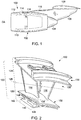
FIG. 2 illustrates additional details of an embodiment of theturbine nozzle 118 ofFIG. 1 . One of these details is an embodiment of aturbine nozzle segment 120. Theturbine nozzle segment 120 comprises an integrally-formed body 122 afirst portion 124 and asecond portion 126 that are delineated by amachining line 128. Thefirst portion 124 comprises anouter band 130 and a portion of afirst vane feature 134. Thesecond portion 126 comprises aninner band 132 and another portion of thefirst vane feature 134. Considering thefirst portion 124 and thesecond portion 126 together, as shown inFIG. 2 , thebody 122 of theturbine nozzle segment 120 comprises theouter band 130, theinner band 132, and thefirst vane feature 134 disposed therebetween. In one embodiment, thefirst vane feature 134 comprises one ormore vanes 136 that extend between theouter band 130 and theinner band 132. As used herein with reference to thebands FIG. 1 ), with the "outer band 130" having a greater radius than the "inner band 132." Theouter band 130, theinner band 132, and thevanes 136 form apath 138 that can direct combustion gases, e.g., to a turbine rotor (not shown) located downstream along the central axis (CA) (FIG. 1 ). In one embodiment, theinner band 132 has a t-bar segment 140 with aflange section 142 and aweb section 144 that extends from a radiallyinner surface 146 of theinner band 132. Although not shown inFIG. 1 , thevanes 136 may have a surface topography with slots, holes, and other features that penetrate the surface of thevanes 136 in various configurations. - The
turbine nozzle segment 120 can be integrally cast with techniques that form theouter band 130, theinner band 132, and thefirst vane feature 134 monolithically. The casting preferably utilizes a high quality superalloy, such as a cobalt or nickel-based superalloy. Certain specifications may further require that the resulting part incorporate a coating with properties for, e.g., corrosion resistance and/or thermal resistance. Gas turbine engines may include a plurality of suchturbine nozzle segments 120 arranged circumferentially in an annular configuration, e.g., about the central axis (CA) (FIG. 1 ). Moreover, whileFIG. 2 shows theturbine nozzle segment 120 with twovanes 136, other configurations of theturbine nozzle segment 120 can have any number ofvanes 136. - Referring to
FIGS. 1 and 2 , during operation of theturbine engine 110, gases traversing theturbine engine 110 from an area forward of theturbine nozzle 118 pass over thevanes 136. These gases include hot combustion gases which are corrosive and cause thevanes 136 to crack, corrode, and otherwise degrade. Theturbine nozzle segment 120 can likewise experience damage that can result from local gas stream over-temperature or foreign objects impacting thereon. - As mentioned above, portions of the
turbine nozzle segment 120 may become damaged to the point where it cannot be repaired by known repair processes. The present disclosure provides methods of repairing theturbine nozzle segment 120 that retains theinner band 132 and discards theouter band 130 andvanes 136. In one embodiment, the methods separate thefirst portion 124 from thesecond portion 126 such as along themachining line 128, remove any excess material, and secure a replacement part (not shown) to theinner band 132 so as to permit operation of the turbine nozzles described herein. This method is particular advantageous because thevanes 136 may include internal features that distribute cooling air to other portions of theturbine nozzle segment 120. The cooling functions may be irreparably damaged or lost during other repairs, i.e., those that do not contemplate aspects of theturbine nozzle segment 120 that accommodate the cooling features. As set forth below, however, embodiments of the method utilize the replacement part, which replicates the necessary cooling features as well as other features (e.g., materials) in order for repair of theturbine nozzle segment 120 to be successful. - With continuing reference to
FIG. 2 ,FIG. 3 provides a flow diagram of an embodiment of a repair method 200. The method 200 comprises, atblock 202, determining a turbine nozzle segment needs repair and, atblock 204, exposing the turbine nozzle section in the turbine engine. The method 200 can also comprise, atblock 206, modifying the turbine nozzle segment, atblock 208, repairing the turbine nozzle by replacing a first portion of the turbine nozzle segment with a replacement part and, atblock 210, securing the replacement part to the second portion. - In one embodiment, technicians can use various techniques to diagnose and identify failures in the turbine nozzle sections. Diagnosis may occur during routine maintenance, wherein the turbine nozzle sections may be exposed (e.g., at block 204) before actual diagnosis (e.g., at block 202) occurs. On the other hand, systems may provide automated alarms or other indicators that identify the particular turbine nozzle segment that may need service and repair.
- Modifications to the turbine nozzle segment may require various machining and/or processes that change the physical structure of the turbine nozzle segment. This element of the method 200 (e.g., at block 206) separates the
first portion 124 from thesecond portion 126. In one example, the technician discards the first portion 124 (with theouter band 130 and the vanes 136). In one embodiment, the method 200 may include performing one or more secondary operations (e.g., grinding, deburring, cutting, bonding) to prepare theinner band 132 to receive and secure the replacement part, which the disclosure describes in more detail below. -
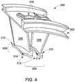
FIG. 4 provides an example of areplacement part 300 for use in embodiments of the repair methods of the present disclosure. Thereplacement part 300 includes a secondouter band 302 and asecond vane feature 304 with one or more airfoils 306 (also "vanes 306"). Thesecond vane feature 304 includes abottom segment 308, where each of thevanes 306 have abase feature 310 with acooling feature 312 that includes lower cooling holes 314. The secondouter band 302 may include corresponding outer cooling holes 316 which receive fluids including liquids and, more commonly, air and other gases common to turbine engines. Although not shown herein, the secondouter band 302, thevanes 306, and thebase feature 310 may include various configurations of bores, apertures, and other features that direct the fluids between thelower cooling holes 314 and the outer cooling holes 316. - The
replacement part 300 replicates the portions of the turbine nozzle segment that is removed. Like the turbine nozzle segment, thereplacement part 300 can be cast and/or can otherwise integrate theouter band 302 and thevanes 306 together into a single, monolithic part. This construction can simplify the repair method as well as reduce costs to manufacture thereplacement part 300. Thebase feature 310 can have a form factor that provides sufficient material to incorporate thecooling feature 312. This form factor can have various shapes and, in one construction, the form factor has a non-airfoil shape with a periphery that includes material in excess of the material that thevanes 306 comprise. The periphery have any form factor, depending on turbine and/or engine design specifications. That is, the periphery can outline shapes of varying degrees of uniformity, wherein for example rectangular-type shapes have a high degree of uniformity and random shapes have a low degree of uniformity. -
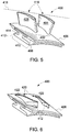
FIGS. 5 and 6 illustrate an exemplaryinner band 400 that can result from performing all or a portion of one or more of the exemplary methods outlined above. InFIG. 5 , theinner band 400 includes afirst vane feature 402 withvanes 404 and aninner band member 406 with a radiallyinner surface 408. Theinner band 400 also includes a t-bar segment 410 having aflange section 412 and aweb section 414 that extends from the radiallyinner surface 408. Particular to this example of theinner band 400, thevanes 404form vane remnants 416, which comprise residual material of thevane 404 that may remain after cutting along amachining line 418. -
FIG. 6 illustrates theinner band 400 without thevane remnants 416. More particularly, theinner band 400 includesrecesses 420, which extend through the material of theinner band member 406 and expose the top of theweb section 414. Therecess 420 have aperipheral wall 422 that defines the shape of therecess 420. In one example, the shape corresponds to the shape and configuration of the base feature (e.g., the base feature 310) of the replacement part. This shape permits therecess 420 to receive the base feature and to locate features of the replacement part (e.g., the lower cooling holes 314 (FIG. 4 )) relative to theinner band member 406. In one embodiment, therecesses 420 include a non-airfoil shaped recess. - Referring next to
FIG. 7 , and also toFIGS. 4-6 , another example of arepair method 500 is illustrated. As mentioned above, examples of the repair methods, includingrepair method 500, remove the outer band and the vanes from the turbine nozzle segment and replace each of these components with a suitably configuredreplacement part 300. To accommodate for a form factor of thebase feature 310 and to integrate thebase feature 310 with theinner band 400, however, themethod 500 may also include modifying theinner band 400 so as to receive thebase feature 310 and/or to position thelower cooling holes 314 in position to direct cooling air below theinner band member 406 and into the gap formed between theinner band member 406 and theflange section 412. - In one embodiment, the
method 500 includes, atblock 502, cutting axially through the first vane feature 402 (e.g., along the machining line 418). Themethod 500 also includes, atblock 504, removing thefirst vane feature 402 from theinner band 400. Themethod 500 may include, atblock 506, grinding thevane remnants 416 from theinner band 400 and/or, in one example, applying other suitable techniques to clean and remove material from theinner band member 406. Themethod 500 further includes, atblock 508, forming therecesses 420, which may include, atblock 510, positioning a sacrificial guard and, atblock 512, implementing electric discharge machining ("EDM") processes to remove material of theinner band member 406. Themethod 500 still further includes, atblock 514, positioning a replacement part in therecesses 420 of theinner band 400 and, atblock 516, joining the replacement part to theinner band 400. - Embodiments of the
method 500 may utilize a plunge EDM process in which tooling for the EDM process enters theinner band member 406 from the top or, in other words, opposite the radiallyinner surface 408. The tooling may plunge to a prescribed depth to remove material of theinner band member 406 and form therecesses 420. In one embodiment, the tooling has a shape that corresponds to the shape and form factor of thebase feature 310 of thevanes 306. Dimensions for the tooling shape (and therecesses 420 that result therefrom) permit effective bonding of thereplacement part 300 and theinner band 400. - Bonding may occur by brazing, welding, and or other suitable bonding technique. For applications such as aircraft and other turbine engines, which expose the turbine nozzle segment to high thermal gradients, brazing is generally preferred. Examples of the
method 500 prescribe bonding along the peripheral edge of the base feature 310 (of the replacement part 300) and theinner band member 406. In one example, the bonding operation includes applying one or more tack welds around thebase feature 310 and applying the final brazing material/structure. - In some cases, one or more aspects of the embodiments of the
repair methods 200 and 500 will be performed on a fully assembled turbine engine, so equipment for cutting operations in such cases will conform to that purpose. Examples of cutting operations that can be used on a fully assembled turbine engine can use an abrasive cutting wheel, a laser, etc. In other example, cutting can be done using nonconventional means such as EDM processes discussed above. After separation, the unsalvageable structure may be scraped. - In one embodiment, the
method 500 may also include stripping any coating materials (such as corrosion or thermal resistant coatings) that may be present. The coating material may be stripped using any suitable technique, such as grit blasting, chemical baths, and the like, or by a combination of such techniques. Themethod 500 may also include repairing cracks in theinner band 400 as well as other repair procedures that, e.g., may improve the integrity of theinner band 400. Such repairs can be performed using known repair techniques including those such as alloy brazing, alloy build up, welding and the like. These conventional repairs will be carried out as needed depending on the condition of theinner band 400. -
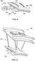
FIG. 8 illustrates an example of asacrificial guard 600 for use in themethod 500. Thesacrificial guard 600 is shown in its uninstalled configuration relative to, e.g., an example of aninner band 602. Theinner band 602 comprises vaneremnants 604, aninner band member 606, and a t-bar section 608 with aflange section 610 and aweb section 612. Surrounding thevane remnants 604 are the outlines ofrecess 614, which the technician can form using, e.g., the plunge EDM process discussed above. - The
sacrificial guard 600 comprises a pair ofelongated legs 616 that form aslot 618. Thesacrificial guard 600 protects the structure of the t-bar section 608. More particularly, thesacrificial guard 600 may prevent removal of material from theinner band 602 and, in one implementation, thesacrificial guard 600 protects theweb section 612 as thevane remnants 604 are removed and the EDM process forms therecesses 614 in theinner band 602. In one example, thesacrificial guard 600 comprises a non-conductive material that interrupts the EDM process. While this disclosure contemplates any number of configurations of thesacrificial guard 600, Theslot 618 is sized and configured so that thesacrificial guard 600 can surround theweb section 612 when thesacrificial guard 600 is in position into the gap between theinner band member 606 and theflange section 610. Each of theelongated legs 616 can extend into the gap, and in one example theelongated legs 616 extend substantially through theinner band 602 so as to project out or near the side opposite the point of insertion. This configuration may restrict the depth the tooling for the EDM process will effectively remove material. -
FIG. 9 depicts an example of a repairedturbine nozzle segment 700, which may result from performing one or more steps (or combinations thereof) of theexemplary methods 200 and 500. The repairedturbine nozzle segment 700 comprises areplacement part 702 and aninner band 704. In one embodiment, thereplacement part 702 comprises the same material as theinner band 704 to produce a repairedturbine nozzle segment 700 that retains the material properties of the original nozzle segment (e.g., turbine nozzle segment 120). However, in other embodiments, the replacement casting 702 comprises different material such as in one example an alloy having enhanced material properties. Differences in the constituent materials may arise during the service life of a gas turbine engine component such as the turbine nozzle segment, where improvements made to alloys become suitable for use with such components are developed. Traditionally, technicians would have to replace existing components with new components fabricated from the improved alloy to realize the enhanced material properties. However, by fabricating the replacement casting 602 from the improved alloy, the repairednozzle segment 700 will obtain, in part, the enhanced material properties. - The replacement casting 700 may also have modified design features compared to the original nozzle segment. Such features may arise during the service life of a turbine engine component such as the turbine nozzle segment, where designs improve and features of the component may change. The turbine nozzle segment may comprise a first design having particular aerodynamic, thermodynamic, and mechanical aspects. For example, the vanes may have a first airfoil definition which incorporates particular dimensional arrangements of e.g., the leading and trailing edges of the vanes. The replacement casting 702 may incorporate changes to the design of the vanes, where the vanes have a second airfoil definition that incorporates certain improvements to enhance performance. Accordingly, implementation of the repair methods resulting in the repaired
turbine nozzle segment 600 that obtains the benefit of the design improvements without having to replace the entire turbine nozzle segment. - This written description uses examples to disclose embodiments of the invention, including the best mode, and also to enable any person skilled in the art to practice the invention, including making and using any devices or systems and performing any incorporated methods. The patentable scope of the invention is defined by the claims, and may include other examples that occur to those skilled in the art. Such other examples are intended to be within the scope of the claims if they have structural elements that do not differ from the literal language of the claims, or if they include equivalent structural elements with insubstantial differences from the literal language of the claims.
Claims (3)
- A method (500) of repairing a turbine nozzle segment (120), the turbine nozzle segment comprising an outer band (130), an inner band (132, 602) and a vane (136) extending between the outer band and the inner band, the method comprising:repairing the turbine nozzle segment (120) by replacing the outer band and the vane of the turbine nozzle segment (120) with a replacement part (300), the replacement part comprising an outer band (302) and a vane (306) integrally formed with the outer band (302),wherein the vane (306) of the replacement part (300) comprises a bottom segment (310) with a cooling hole (314) that directs fluid to a position that is radially interior to a radially inner surface of the inner band (132, 602) of the turbine nozzle segment (120);wherein the method further comprises:forming (508) a recess (614) in the inner band (132, 602), wherein the recess (614) is sized and configured to receive the bottom segment (310) therein;wherein the forming (508) the recess (614) comprises: positioning (510) a sacrificial part (600) and performing (512) a plunge electrical discharge machining process, wherein the sacrificial part (600) has material properties that limits penetration of tooling for the plunge electrical discharge machining process into the inner band (132, 602) of the turbine nozzle segment (120); wherein the sacrificial part (600) comprises a non-conductive material.
- A method (500) according to claim 1, wherein the inner band (132, 602) comprises a T-bar segment (608) secured thereto.
- A method according to either of claim 1 or 2, further comprising securing the bottom segment (310) to the inner band (132, 602).
Applications Claiming Priority (1)
| Application Number | Priority Date | Filing Date | Title |
|---|---|---|---|
| US13/163,474 US9447689B2 (en) | 2011-06-17 | 2011-06-17 | Method of repairing a turbine nozzle segment in a turbine engine |
Publications (3)
| Publication Number | Publication Date |
|---|---|
| EP2535512A2 EP2535512A2 (en) | 2012-12-19 |
| EP2535512A3 EP2535512A3 (en) | 2018-05-30 |
| EP2535512B1 true EP2535512B1 (en) | 2019-08-07 |
Family
ID=46318980
Family Applications (1)
| Application Number | Title | Priority Date | Filing Date |
|---|---|---|---|
| EP12172283.9A Active EP2535512B1 (en) | 2011-06-17 | 2012-06-15 | Method of repairing a turbine nozzle segment in a turbine engine |
Country Status (4)
| Country | Link |
|---|---|
| US (1) | US9447689B2 (en) |
| EP (1) | EP2535512B1 (en) |
| JP (1) | JP2013002444A (en) |
| CA (1) | CA2779851C (en) |
Families Citing this family (7)
| Publication number | Priority date | Publication date | Assignee | Title |
|---|---|---|---|---|
| US9447689B2 (en) * | 2011-06-17 | 2016-09-20 | General Electric Company | Method of repairing a turbine nozzle segment in a turbine engine |
| US9863249B2 (en) * | 2012-12-04 | 2018-01-09 | Siemens Energy, Inc. | Pre-sintered preform repair of turbine blades |
| GB2508886A (en) * | 2012-12-14 | 2014-06-18 | Rolls Royce Plc | Aligning replacement aerofoil vane with platform |
| JP6045389B2 (en) * | 2013-02-18 | 2016-12-14 | 三菱重工業株式会社 | Turbine nozzle and manufacturing method thereof |
| US10119403B2 (en) * | 2014-02-13 | 2018-11-06 | United Technologies Corporation | Mistuned concentric airfoil assembly and method of mistuning same |
| CN106944683B (en) * | 2017-03-17 | 2019-07-26 | 广东工业大学 | A kind of electric discharge turning machining device that tool-electrode compensates automatically and method |
| CN114278435B (en) * | 2020-09-28 | 2023-05-16 | 中国航发商用航空发动机有限责任公司 | Compressor, gas turbine engine, adjustable vane assembly, and method of assembly |
Family Cites Families (17)
| Publication number | Priority date | Publication date | Assignee | Title |
|---|---|---|---|---|
| US5248240A (en) * | 1993-02-08 | 1993-09-28 | General Electric Company | Turbine stator vane assembly |
| US5758416A (en) * | 1996-12-05 | 1998-06-02 | General Electric Company | Method for repairing a turbine engine vane segment |
| US5797725A (en) | 1997-05-23 | 1998-08-25 | Allison Advanced Development Company | Gas turbine engine vane and method of manufacture |
| US6354797B1 (en) | 2000-07-27 | 2002-03-12 | General Electric Company | Brazeless fillet turbine nozzle |
| US6416278B1 (en) * | 2000-11-16 | 2002-07-09 | General Electric Company | Turbine nozzle segment and method of repairing same |
| US6579061B1 (en) | 2001-07-27 | 2003-06-17 | General Electric Company | Selective step turbine nozzle |
| US20030106215A1 (en) * | 2001-12-11 | 2003-06-12 | General Electric Company | Turbine nozzle segment and method of repairing same |
| US20040064930A1 (en) * | 2002-10-08 | 2004-04-08 | George Gunn | Method of forming cooling apertures in airfoil-shaped blades |
| US6793457B2 (en) * | 2002-11-15 | 2004-09-21 | General Electric Company | Fabricated repair of cast nozzle |
| US6905308B2 (en) * | 2002-11-20 | 2005-06-14 | General Electric Company | Turbine nozzle segment and method of repairing same |
| US7172389B2 (en) * | 2004-11-16 | 2007-02-06 | General Electric Company | Method for making a repaired turbine engine stationary vane assembly and repaired assembly |
| US7185433B2 (en) * | 2004-12-17 | 2007-03-06 | General Electric Company | Turbine nozzle segment and method of repairing same |
| US7434313B2 (en) | 2005-12-22 | 2008-10-14 | General Electric Company | Method for repairing a turbine engine vane assembly and repaired assembly |
| US7837437B2 (en) | 2007-03-07 | 2010-11-23 | General Electric Company | Turbine nozzle segment and repair method |
| US8210807B2 (en) * | 2008-08-28 | 2012-07-03 | United Technologies Corporation | Gas turbine airfoil assemblies and methods of repair |
| JP5422217B2 (en) | 2009-02-06 | 2014-02-19 | 三菱重工業株式会社 | Gas turbine blade and gas turbine |
| US9447689B2 (en) * | 2011-06-17 | 2016-09-20 | General Electric Company | Method of repairing a turbine nozzle segment in a turbine engine |
-
2011
- 2011-06-17 US US13/163,474 patent/US9447689B2/en active Active
-
2012
- 2012-06-14 JP JP2012134321A patent/JP2013002444A/en active Pending
- 2012-06-14 CA CA2779851A patent/CA2779851C/en not_active Expired - Fee Related
- 2012-06-15 EP EP12172283.9A patent/EP2535512B1/en active Active
Non-Patent Citations (1)
| Title |
|---|
| None * |
Also Published As
| Publication number | Publication date |
|---|---|
| JP2013002444A (en) | 2013-01-07 |
| CA2779851C (en) | 2019-06-11 |
| US9447689B2 (en) | 2016-09-20 |
| EP2535512A3 (en) | 2018-05-30 |
| US20120317809A1 (en) | 2012-12-20 |
| CA2779851A1 (en) | 2012-12-17 |
| EP2535512A2 (en) | 2012-12-19 |
Similar Documents
| Publication | Publication Date | Title |
|---|---|---|
| EP2535512B1 (en) | Method of repairing a turbine nozzle segment in a turbine engine | |
| US6494677B1 (en) | Turbine nozzle segment and method of repairing same | |
| KR100672134B1 (en) | Turbine nozzle segment and method of repairing same | |
| EP1674665B1 (en) | Turbine nozzle segment and method of repairing the same | |
| JP4474146B2 (en) | Assembling repair of casting nozzle | |
| US6905308B2 (en) | Turbine nozzle segment and method of repairing same | |
| EP1099508B1 (en) | Turbine nozzle segment and method of repairing same | |
| US20030106215A1 (en) | Turbine nozzle segment and method of repairing same | |
| US10875131B2 (en) | Repair or remanufacture of blade platform for a gas turbine engine | |
| CA2623675C (en) | Turbine nozzle segment and repair method | |
| NL2002340C2 (en) | Method for repairing a cooled turbine nozzle segment. |
Legal Events
| Date | Code | Title | Description |
|---|---|---|---|
| PUAI | Public reference made under article 153(3) epc to a published international application that has entered the european phase |
Free format text: ORIGINAL CODE: 0009012 |
|
| AK | Designated contracting states |
Kind code of ref document: A2 Designated state(s): AL AT BE BG CH CY CZ DE DK EE ES FI FR GB GR HR HU IE IS IT LI LT LU LV MC MK MT NL NO PL PT RO RS SE SI SK SM TR |
|
| AX | Request for extension of the european patent |
Extension state: BA ME |
|
| PUAL | Search report despatched |
Free format text: ORIGINAL CODE: 0009013 |
|
| AK | Designated contracting states |
Kind code of ref document: A3 Designated state(s): AL AT BE BG CH CY CZ DE DK EE ES FI FR GB GR HR HU IE IS IT LI LT LU LV MC MK MT NL NO PL PT RO RS SE SI SK SM TR |
|
| AX | Request for extension of the european patent |
Extension state: BA ME |
|
| RIC1 | Information provided on ipc code assigned before grant |
Ipc: F01D 5/00 20060101AFI20180424BHEP Ipc: F01D 9/02 20060101ALI20180424BHEP Ipc: F01D 9/04 20060101ALI20180424BHEP Ipc: B23P 6/00 20060101ALI20180424BHEP |
|
| STAA | Information on the status of an ep patent application or granted ep patent |
Free format text: STATUS: REQUEST FOR EXAMINATION WAS MADE |
|
| 17P | Request for examination filed |
Effective date: 20181130 |
|
| RBV | Designated contracting states (corrected) |
Designated state(s): AL AT BE BG CH CY CZ DE DK EE ES FI FR GB GR HR HU IE IS IT LI LT LU LV MC MK MT NL NO PL PT RO RS SE SI SK SM TR |
|
| RIC1 | Information provided on ipc code assigned before grant |
Ipc: F01D 5/00 20060101AFI20181218BHEP Ipc: F01D 9/04 20060101ALI20181218BHEP Ipc: F01D 9/02 20060101ALI20181218BHEP Ipc: B23P 6/00 20060101ALI20181218BHEP |
|
| GRAP | Despatch of communication of intention to grant a patent |
Free format text: ORIGINAL CODE: EPIDOSNIGR1 |
|
| STAA | Information on the status of an ep patent application or granted ep patent |
Free format text: STATUS: GRANT OF PATENT IS INTENDED |
|
| INTG | Intention to grant announced |
Effective date: 20190201 |
|
| GRAS | Grant fee paid |
Free format text: ORIGINAL CODE: EPIDOSNIGR3 |
|
| GRAJ | Information related to disapproval of communication of intention to grant by the applicant or resumption of examination proceedings by the epo deleted |
Free format text: ORIGINAL CODE: EPIDOSDIGR1 |
|
| GRAL | Information related to payment of fee for publishing/printing deleted |
Free format text: ORIGINAL CODE: EPIDOSDIGR3 |
|
| STAA | Information on the status of an ep patent application or granted ep patent |
Free format text: STATUS: REQUEST FOR EXAMINATION WAS MADE |
|
| GRAR | Information related to intention to grant a patent recorded |
Free format text: ORIGINAL CODE: EPIDOSNIGR71 |
|
| STAA | Information on the status of an ep patent application or granted ep patent |
Free format text: STATUS: GRANT OF PATENT IS INTENDED |
|
| GRAA | (expected) grant |
Free format text: ORIGINAL CODE: 0009210 |
|
| STAA | Information on the status of an ep patent application or granted ep patent |
Free format text: STATUS: THE PATENT HAS BEEN GRANTED |
|
| INTC | Intention to grant announced (deleted) | ||
| INTG | Intention to grant announced |
Effective date: 20190627 |
|
| AK | Designated contracting states |
Kind code of ref document: B1 Designated state(s): AL AT BE BG CH CY CZ DE DK EE ES FI FR GB GR HR HU IE IS IT LI LT LU LV MC MK MT NL NO PL PT RO RS SE SI SK SM TR |
|
| REG | Reference to a national code |
Ref country code: GB Ref legal event code: FG4D |
|
| REG | Reference to a national code |
Ref country code: CH Ref legal event code: EP Ref country code: AT Ref legal event code: REF Ref document number: 1164170 Country of ref document: AT Kind code of ref document: T Effective date: 20190815 |
|
| REG | Reference to a national code |
Ref country code: DE Ref legal event code: R096 Ref document number: 602012062618 Country of ref document: DE |
|
| REG | Reference to a national code |
Ref country code: IE Ref legal event code: FG4D |
|
| REG | Reference to a national code |
Ref country code: NL Ref legal event code: MP Effective date: 20190807 |
|
| REG | Reference to a national code |
Ref country code: LT Ref legal event code: MG4D |
|
| PG25 | Lapsed in a contracting state [announced via postgrant information from national office to epo] |
Ref country code: FI Free format text: LAPSE BECAUSE OF FAILURE TO SUBMIT A TRANSLATION OF THE DESCRIPTION OR TO PAY THE FEE WITHIN THE PRESCRIBED TIME-LIMIT Effective date: 20190807 Ref country code: LT Free format text: LAPSE BECAUSE OF FAILURE TO SUBMIT A TRANSLATION OF THE DESCRIPTION OR TO PAY THE FEE WITHIN THE PRESCRIBED TIME-LIMIT Effective date: 20190807 Ref country code: NO Free format text: LAPSE BECAUSE OF FAILURE TO SUBMIT A TRANSLATION OF THE DESCRIPTION OR TO PAY THE FEE WITHIN THE PRESCRIBED TIME-LIMIT Effective date: 20191107 Ref country code: SE Free format text: LAPSE BECAUSE OF FAILURE TO SUBMIT A TRANSLATION OF THE DESCRIPTION OR TO PAY THE FEE WITHIN THE PRESCRIBED TIME-LIMIT Effective date: 20190807 Ref country code: BG Free format text: LAPSE BECAUSE OF FAILURE TO SUBMIT A TRANSLATION OF THE DESCRIPTION OR TO PAY THE FEE WITHIN THE PRESCRIBED TIME-LIMIT Effective date: 20191107 Ref country code: NL Free format text: LAPSE BECAUSE OF FAILURE TO SUBMIT A TRANSLATION OF THE DESCRIPTION OR TO PAY THE FEE WITHIN THE PRESCRIBED TIME-LIMIT Effective date: 20190807 Ref country code: HR Free format text: LAPSE BECAUSE OF FAILURE TO SUBMIT A TRANSLATION OF THE DESCRIPTION OR TO PAY THE FEE WITHIN THE PRESCRIBED TIME-LIMIT Effective date: 20190807 Ref country code: PT Free format text: LAPSE BECAUSE OF FAILURE TO SUBMIT A TRANSLATION OF THE DESCRIPTION OR TO PAY THE FEE WITHIN THE PRESCRIBED TIME-LIMIT Effective date: 20191209 |
|
| REG | Reference to a national code |
Ref country code: AT Ref legal event code: MK05 Ref document number: 1164170 Country of ref document: AT Kind code of ref document: T Effective date: 20190807 |
|
| PG25 | Lapsed in a contracting state [announced via postgrant information from national office to epo] |
Ref country code: RS Free format text: LAPSE BECAUSE OF FAILURE TO SUBMIT A TRANSLATION OF THE DESCRIPTION OR TO PAY THE FEE WITHIN THE PRESCRIBED TIME-LIMIT Effective date: 20190807 Ref country code: IS Free format text: LAPSE BECAUSE OF FAILURE TO SUBMIT A TRANSLATION OF THE DESCRIPTION OR TO PAY THE FEE WITHIN THE PRESCRIBED TIME-LIMIT Effective date: 20191207 Ref country code: GR Free format text: LAPSE BECAUSE OF FAILURE TO SUBMIT A TRANSLATION OF THE DESCRIPTION OR TO PAY THE FEE WITHIN THE PRESCRIBED TIME-LIMIT Effective date: 20191108 Ref country code: ES Free format text: LAPSE BECAUSE OF FAILURE TO SUBMIT A TRANSLATION OF THE DESCRIPTION OR TO PAY THE FEE WITHIN THE PRESCRIBED TIME-LIMIT Effective date: 20190807 Ref country code: AL Free format text: LAPSE BECAUSE OF FAILURE TO SUBMIT A TRANSLATION OF THE DESCRIPTION OR TO PAY THE FEE WITHIN THE PRESCRIBED TIME-LIMIT Effective date: 20190807 Ref country code: LV Free format text: LAPSE BECAUSE OF FAILURE TO SUBMIT A TRANSLATION OF THE DESCRIPTION OR TO PAY THE FEE WITHIN THE PRESCRIBED TIME-LIMIT Effective date: 20190807 |
|
| PG25 | Lapsed in a contracting state [announced via postgrant information from national office to epo] |
Ref country code: TR Free format text: LAPSE BECAUSE OF FAILURE TO SUBMIT A TRANSLATION OF THE DESCRIPTION OR TO PAY THE FEE WITHIN THE PRESCRIBED TIME-LIMIT Effective date: 20190807 |
|
| PG25 | Lapsed in a contracting state [announced via postgrant information from national office to epo] |
Ref country code: PL Free format text: LAPSE BECAUSE OF FAILURE TO SUBMIT A TRANSLATION OF THE DESCRIPTION OR TO PAY THE FEE WITHIN THE PRESCRIBED TIME-LIMIT Effective date: 20190807 Ref country code: EE Free format text: LAPSE BECAUSE OF FAILURE TO SUBMIT A TRANSLATION OF THE DESCRIPTION OR TO PAY THE FEE WITHIN THE PRESCRIBED TIME-LIMIT Effective date: 20190807 Ref country code: DK Free format text: LAPSE BECAUSE OF FAILURE TO SUBMIT A TRANSLATION OF THE DESCRIPTION OR TO PAY THE FEE WITHIN THE PRESCRIBED TIME-LIMIT Effective date: 20190807 Ref country code: AT Free format text: LAPSE BECAUSE OF FAILURE TO SUBMIT A TRANSLATION OF THE DESCRIPTION OR TO PAY THE FEE WITHIN THE PRESCRIBED TIME-LIMIT Effective date: 20190807 Ref country code: IT Free format text: LAPSE BECAUSE OF FAILURE TO SUBMIT A TRANSLATION OF THE DESCRIPTION OR TO PAY THE FEE WITHIN THE PRESCRIBED TIME-LIMIT Effective date: 20190807 Ref country code: RO Free format text: LAPSE BECAUSE OF FAILURE TO SUBMIT A TRANSLATION OF THE DESCRIPTION OR TO PAY THE FEE WITHIN THE PRESCRIBED TIME-LIMIT Effective date: 20190807 |
|
| PG25 | Lapsed in a contracting state [announced via postgrant information from national office to epo] |
Ref country code: SK Free format text: LAPSE BECAUSE OF FAILURE TO SUBMIT A TRANSLATION OF THE DESCRIPTION OR TO PAY THE FEE WITHIN THE PRESCRIBED TIME-LIMIT Effective date: 20190807 Ref country code: CZ Free format text: LAPSE BECAUSE OF FAILURE TO SUBMIT A TRANSLATION OF THE DESCRIPTION OR TO PAY THE FEE WITHIN THE PRESCRIBED TIME-LIMIT Effective date: 20190807 Ref country code: IS Free format text: LAPSE BECAUSE OF FAILURE TO SUBMIT A TRANSLATION OF THE DESCRIPTION OR TO PAY THE FEE WITHIN THE PRESCRIBED TIME-LIMIT Effective date: 20200224 Ref country code: SM Free format text: LAPSE BECAUSE OF FAILURE TO SUBMIT A TRANSLATION OF THE DESCRIPTION OR TO PAY THE FEE WITHIN THE PRESCRIBED TIME-LIMIT Effective date: 20190807 |
|
| REG | Reference to a national code |
Ref country code: DE Ref legal event code: R097 Ref document number: 602012062618 Country of ref document: DE |
|
| PLBE | No opposition filed within time limit |
Free format text: ORIGINAL CODE: 0009261 |
|
| STAA | Information on the status of an ep patent application or granted ep patent |
Free format text: STATUS: NO OPPOSITION FILED WITHIN TIME LIMIT |
|
| PG2D | Information on lapse in contracting state deleted |
Ref country code: IS |
|
| 26N | No opposition filed |
Effective date: 20200603 |
|
| PG25 | Lapsed in a contracting state [announced via postgrant information from national office to epo] |
Ref country code: SI Free format text: LAPSE BECAUSE OF FAILURE TO SUBMIT A TRANSLATION OF THE DESCRIPTION OR TO PAY THE FEE WITHIN THE PRESCRIBED TIME-LIMIT Effective date: 20190807 |
|
| PG25 | Lapsed in a contracting state [announced via postgrant information from national office to epo] |
Ref country code: MC Free format text: LAPSE BECAUSE OF FAILURE TO SUBMIT A TRANSLATION OF THE DESCRIPTION OR TO PAY THE FEE WITHIN THE PRESCRIBED TIME-LIMIT Effective date: 20190807 |
|
| REG | Reference to a national code |
Ref country code: CH Ref legal event code: PL |
|
| PG25 | Lapsed in a contracting state [announced via postgrant information from national office to epo] |
Ref country code: LU Free format text: LAPSE BECAUSE OF NON-PAYMENT OF DUE FEES Effective date: 20200615 |
|
| REG | Reference to a national code |
Ref country code: BE Ref legal event code: MM Effective date: 20200630 |
|
| PG25 | Lapsed in a contracting state [announced via postgrant information from national office to epo] |
Ref country code: IE Free format text: LAPSE BECAUSE OF NON-PAYMENT OF DUE FEES Effective date: 20200615 Ref country code: LI Free format text: LAPSE BECAUSE OF NON-PAYMENT OF DUE FEES Effective date: 20200630 Ref country code: CH Free format text: LAPSE BECAUSE OF NON-PAYMENT OF DUE FEES Effective date: 20200630 |
|
| PG25 | Lapsed in a contracting state [announced via postgrant information from national office to epo] |
Ref country code: BE Free format text: LAPSE BECAUSE OF NON-PAYMENT OF DUE FEES Effective date: 20200630 |
|
| PG25 | Lapsed in a contracting state [announced via postgrant information from national office to epo] |
Ref country code: MT Free format text: LAPSE BECAUSE OF FAILURE TO SUBMIT A TRANSLATION OF THE DESCRIPTION OR TO PAY THE FEE WITHIN THE PRESCRIBED TIME-LIMIT Effective date: 20190807 Ref country code: CY Free format text: LAPSE BECAUSE OF FAILURE TO SUBMIT A TRANSLATION OF THE DESCRIPTION OR TO PAY THE FEE WITHIN THE PRESCRIBED TIME-LIMIT Effective date: 20190807 |
|
| PG25 | Lapsed in a contracting state [announced via postgrant information from national office to epo] |
Ref country code: MK Free format text: LAPSE BECAUSE OF FAILURE TO SUBMIT A TRANSLATION OF THE DESCRIPTION OR TO PAY THE FEE WITHIN THE PRESCRIBED TIME-LIMIT Effective date: 20190807 |
|
| P01 | Opt-out of the competence of the unified patent court (upc) registered |
Effective date: 20230411 |
|
| PGFP | Annual fee paid to national office [announced via postgrant information from national office to epo] |
Ref country code: GB Payment date: 20240521 Year of fee payment: 13 |
|
| PGFP | Annual fee paid to national office [announced via postgrant information from national office to epo] |
Ref country code: DE Payment date: 20240521 Year of fee payment: 13 |
|
| PGFP | Annual fee paid to national office [announced via postgrant information from national office to epo] |
Ref country code: FR Payment date: 20240521 Year of fee payment: 13 |