EP3578096A1 - Wearable-vorrichtung - Google Patents
Wearable-vorrichtung Download PDFInfo
- Publication number
- EP3578096A1 EP3578096A1 EP18176595.9A EP18176595A EP3578096A1 EP 3578096 A1 EP3578096 A1 EP 3578096A1 EP 18176595 A EP18176595 A EP 18176595A EP 3578096 A1 EP3578096 A1 EP 3578096A1
- Authority
- EP
- European Patent Office
- Prior art keywords
- sensor
- base layer
- meander
- layer
- contact
- Prior art date
- Legal status (The legal status is an assumption and is not a legal conclusion. Google has not performed a legal analysis and makes no representation as to the accuracy of the status listed.)
- Withdrawn
Links
- 239000000853 adhesive Substances 0.000 claims description 6
- 230000001070 adhesive effect Effects 0.000 claims description 6
- 238000012545 processing Methods 0.000 claims description 6
- 239000012943 hotmelt Substances 0.000 claims description 3
- 239000004820 Pressure-sensitive adhesive Substances 0.000 claims description 2
- 239000002390 adhesive tape Substances 0.000 claims description 2
- 238000000034 method Methods 0.000 abstract description 9
- 238000003475 lamination Methods 0.000 abstract description 8
- 230000008569 process Effects 0.000 abstract description 7
- 238000013461 design Methods 0.000 description 10
- 230000033001 locomotion Effects 0.000 description 8
- 238000012544 monitoring process Methods 0.000 description 8
- 230000006870 function Effects 0.000 description 4
- 239000006260 foam Substances 0.000 description 3
- 239000004642 Polyimide Substances 0.000 description 2
- 230000008901 benefit Effects 0.000 description 2
- 230000008878 coupling Effects 0.000 description 2
- 238000010168 coupling process Methods 0.000 description 2
- 238000005859 coupling reaction Methods 0.000 description 2
- 230000000694 effects Effects 0.000 description 2
- 230000005055 memory storage Effects 0.000 description 2
- 230000004048 modification Effects 0.000 description 2
- 238000012986 modification Methods 0.000 description 2
- 238000012806 monitoring device Methods 0.000 description 2
- 229920000139 polyethylene terephthalate Polymers 0.000 description 2
- 239000005020 polyethylene terephthalate Substances 0.000 description 2
- 229920001721 polyimide Polymers 0.000 description 2
- 230000001953 sensory effect Effects 0.000 description 2
- 238000002604 ultrasonography Methods 0.000 description 2
- RYGMFSIKBFXOCR-UHFFFAOYSA-N Copper Chemical compound [Cu] RYGMFSIKBFXOCR-UHFFFAOYSA-N 0.000 description 1
- 229910021607 Silver chloride Inorganic materials 0.000 description 1
- 239000004433 Thermoplastic polyurethane Substances 0.000 description 1
- 239000003522 acrylic cement Substances 0.000 description 1
- 230000005540 biological transmission Effects 0.000 description 1
- 238000004590 computer program Methods 0.000 description 1
- 230000003750 conditioning effect Effects 0.000 description 1
- 239000004020 conductor Substances 0.000 description 1
- 229910052802 copper Inorganic materials 0.000 description 1
- 239000010949 copper Substances 0.000 description 1
- 238000005336 cracking Methods 0.000 description 1
- 230000001419 dependent effect Effects 0.000 description 1
- 238000001514 detection method Methods 0.000 description 1
- 238000003745 diagnosis Methods 0.000 description 1
- 208000028659 discharge Diseases 0.000 description 1
- 238000005538 encapsulation Methods 0.000 description 1
- 239000011888 foil Substances 0.000 description 1
- 238000010438 heat treatment Methods 0.000 description 1
- 238000004519 manufacturing process Methods 0.000 description 1
- 230000003287 optical effect Effects 0.000 description 1
- 239000011112 polyethylene naphthalate Substances 0.000 description 1
- -1 polyethylene terephthalate Polymers 0.000 description 1
- 229920000307 polymer substrate Polymers 0.000 description 1
- 229920001296 polysiloxane Polymers 0.000 description 1
- 229920002635 polyurethane Polymers 0.000 description 1
- 239000004814 polyurethane Substances 0.000 description 1
- 229920006264 polyurethane film Polymers 0.000 description 1
- 230000029058 respiratory gaseous exchange Effects 0.000 description 1
- 230000036387 respiratory rate Effects 0.000 description 1
- 238000007789 sealing Methods 0.000 description 1
- 230000008054 signal transmission Effects 0.000 description 1
- 239000013464 silicone adhesive Substances 0.000 description 1
- HKZLPVFGJNLROG-UHFFFAOYSA-M silver monochloride Chemical compound [Cl-].[Ag+] HKZLPVFGJNLROG-UHFFFAOYSA-M 0.000 description 1
- 231100000430 skin reaction Toxicity 0.000 description 1
- 238000003860 storage Methods 0.000 description 1
- 239000004753 textile Substances 0.000 description 1
- 238000002560 therapeutic procedure Methods 0.000 description 1
- 238000001029 thermal curing Methods 0.000 description 1
- 238000009823 thermal lamination Methods 0.000 description 1
- 229920002803 thermoplastic polyurethane Polymers 0.000 description 1
Images

Classifications
-
- A—HUMAN NECESSITIES
- A61—MEDICAL OR VETERINARY SCIENCE; HYGIENE
- A61B—DIAGNOSIS; SURGERY; IDENTIFICATION
- A61B5/00—Measuring for diagnostic purposes; Identification of persons
- A61B5/24—Detecting, measuring or recording bioelectric or biomagnetic signals of the body or parts thereof
- A61B5/25—Bioelectric electrodes therefor
- A61B5/251—Means for maintaining electrode contact with the body
- A61B5/257—Means for maintaining electrode contact with the body using adhesive means, e.g. adhesive pads or tapes
- A61B5/259—Means for maintaining electrode contact with the body using adhesive means, e.g. adhesive pads or tapes using conductive adhesive means, e.g. gels
-
- A—HUMAN NECESSITIES
- A61—MEDICAL OR VETERINARY SCIENCE; HYGIENE
- A61B—DIAGNOSIS; SURGERY; IDENTIFICATION
- A61B5/00—Measuring for diagnostic purposes; Identification of persons
- A61B5/68—Arrangements of detecting, measuring or recording means, e.g. sensors, in relation to patient
- A61B5/6801—Arrangements of detecting, measuring or recording means, e.g. sensors, in relation to patient specially adapted to be attached to or worn on the body surface
- A61B5/683—Means for maintaining contact with the body
- A61B5/6832—Means for maintaining contact with the body using adhesives
- A61B5/6833—Adhesive patches
-
- A—HUMAN NECESSITIES
- A61—MEDICAL OR VETERINARY SCIENCE; HYGIENE
- A61B—DIAGNOSIS; SURGERY; IDENTIFICATION
- A61B5/00—Measuring for diagnostic purposes; Identification of persons
- A61B5/0002—Remote monitoring of patients using telemetry, e.g. transmission of vital signals via a communication network
- A61B5/0004—Remote monitoring of patients using telemetry, e.g. transmission of vital signals via a communication network characterised by the type of physiological signal transmitted
-
- A—HUMAN NECESSITIES
- A61—MEDICAL OR VETERINARY SCIENCE; HYGIENE
- A61B—DIAGNOSIS; SURGERY; IDENTIFICATION
- A61B5/00—Measuring for diagnostic purposes; Identification of persons
- A61B5/02—Detecting, measuring or recording pulse, heart rate, blood pressure or blood flow; Combined pulse/heart-rate/blood pressure determination; Evaluating a cardiovascular condition not otherwise provided for, e.g. using combinations of techniques provided for in this group with electrocardiography or electroauscultation; Heart catheters for measuring blood pressure
- A61B5/024—Detecting, measuring or recording pulse rate or heart rate
- A61B5/02416—Detecting, measuring or recording pulse rate or heart rate using photoplethysmograph signals, e.g. generated by infrared radiation
-
- A—HUMAN NECESSITIES
- A61—MEDICAL OR VETERINARY SCIENCE; HYGIENE
- A61B—DIAGNOSIS; SURGERY; IDENTIFICATION
- A61B5/00—Measuring for diagnostic purposes; Identification of persons
- A61B5/24—Detecting, measuring or recording bioelectric or biomagnetic signals of the body or parts thereof
- A61B5/316—Modalities, i.e. specific diagnostic methods
- A61B5/318—Heart-related electrical modalities, e.g. electrocardiography [ECG]
-
- A—HUMAN NECESSITIES
- A61—MEDICAL OR VETERINARY SCIENCE; HYGIENE
- A61B—DIAGNOSIS; SURGERY; IDENTIFICATION
- A61B5/00—Measuring for diagnostic purposes; Identification of persons
- A61B5/24—Detecting, measuring or recording bioelectric or biomagnetic signals of the body or parts thereof
- A61B5/316—Modalities, i.e. specific diagnostic methods
- A61B5/369—Electroencephalography [EEG]
-
- A—HUMAN NECESSITIES
- A61—MEDICAL OR VETERINARY SCIENCE; HYGIENE
- A61B—DIAGNOSIS; SURGERY; IDENTIFICATION
- A61B5/00—Measuring for diagnostic purposes; Identification of persons
- A61B5/68—Arrangements of detecting, measuring or recording means, e.g. sensors, in relation to patient
- A61B5/6801—Arrangements of detecting, measuring or recording means, e.g. sensors, in relation to patient specially adapted to be attached to or worn on the body surface
- A61B5/6813—Specially adapted to be attached to a specific body part
- A61B5/6814—Head
-
- A—HUMAN NECESSITIES
- A61—MEDICAL OR VETERINARY SCIENCE; HYGIENE
- A61B—DIAGNOSIS; SURGERY; IDENTIFICATION
- A61B5/00—Measuring for diagnostic purposes; Identification of persons
- A61B5/72—Signal processing specially adapted for physiological signals or for diagnostic purposes
-
- A—HUMAN NECESSITIES
- A61—MEDICAL OR VETERINARY SCIENCE; HYGIENE
- A61B—DIAGNOSIS; SURGERY; IDENTIFICATION
- A61B2560/00—Constructional details of operational features of apparatus; Accessories for medical measuring apparatus
- A61B2560/02—Operational features
- A61B2560/0204—Operational features of power management
- A61B2560/0214—Operational features of power management of power generation or supply
-
- A—HUMAN NECESSITIES
- A61—MEDICAL OR VETERINARY SCIENCE; HYGIENE
- A61B—DIAGNOSIS; SURGERY; IDENTIFICATION
- A61B2562/00—Details of sensors; Constructional details of sensor housings or probes; Accessories for sensors
- A61B2562/02—Details of sensors specially adapted for in-vivo measurements
- A61B2562/0219—Inertial sensors, e.g. accelerometers, gyroscopes, tilt switches
-
- A—HUMAN NECESSITIES
- A61—MEDICAL OR VETERINARY SCIENCE; HYGIENE
- A61B—DIAGNOSIS; SURGERY; IDENTIFICATION
- A61B2562/00—Details of sensors; Constructional details of sensor housings or probes; Accessories for sensors
- A61B2562/02—Details of sensors specially adapted for in-vivo measurements
- A61B2562/0271—Thermal or temperature sensors
-
- A—HUMAN NECESSITIES
- A61—MEDICAL OR VETERINARY SCIENCE; HYGIENE
- A61B—DIAGNOSIS; SURGERY; IDENTIFICATION
- A61B2562/00—Details of sensors; Constructional details of sensor housings or probes; Accessories for sensors
- A61B2562/16—Details of sensor housings or probes; Details of structural supports for sensors
- A61B2562/166—Details of sensor housings or probes; Details of structural supports for sensors the sensor is mounted on a specially adapted printed circuit board
Definitions
- This invention relates to wearable devices such as actuators or sensors.
- the invention is of interest for sensors for measuring one or more physiological parameters of a subject, wherein the sensor can be worn by the subject.
- the invention relates to a wearable patch which may implement a photoplethysmographic (PPG) sensor, an electrocardiogram (EGC) sensor, an electroencephalogram sensor (EEG), a wearable ultrasound sensor (US), a wearable heart rate sensor, a wearable galvanic skin response sensor (GSR) or a motion sensor.
- PPG photoplethysmographic
- ECG electrocardiogram
- EEG electroencephalogram
- US wearable ultrasound sensor
- GSR wearable galvanic skin response sensor
- Monitoring of physiological parameters is of increasing interest, to allow for better diagnosis and patient monitoring. It is for example known to provide wearable monitoring devices, such as patches, that subjects can wear in low acuity settings such as the general ward and at home. Better monitoring in general wards is needed to reduce the mortality rate. Also, accountable care drives the need to discharge patients to their home, and continue a level of monitoring at home for a period of time, typically up to 30 days.
- patch comfort is very important, especially in the home monitoring context where it will influence patient adherence.
- reliability of a wearable sensor is important in order to reach the desired period (e.g. 30 days) of home monitoring.
- Wearable devices are convenient to use as they offer increased freedom of movement for the user whilst a physiological parameter is being monitored. In this way, it is possible to measure physiological parameters in a variety of circumstances, for example at different levels of physical exertion of the subject.
- the physiological parameter sensor may be mounted to the user differently in different applications.
- the position of the mounted physiological parameter sensor relative to the subject depends on the type of physiological parameter sensor, and/or the circumstances in which physiological sensing takes place. In general, the physiological parameter sensor should be in contact with the skin but there are other cases in which a physiological parameter sensor should be separated from the subject's body.
- a steady distance between a light sensor and the skin is desired for optimal stability of the sensor signal.
- good contact with the skin is imperative for high quality images.
- the electrodes of ECG monitoring devices or GSR sensors should be in contact with the skin.
- a sensor system which employs multiple different sensing modalities may also have multiple sensing locations.
- This invention relates in particular to wearable systems which make use of contact locations for sensing or actuation.
- the multiple locations may for example relate to monitoring of a single physiological parameter, or multiple parameters.
- these different locations need to be able to communicate electrically with each other, for example so that a single processing site can gather sensing data from the multiple areas.
- This requires connecting conductive tracks between the contact locations. It is known to provide these connecting conductive tracks as meander paths, to provide a degree of stretchability. Flexibility and stretchability are key for comfort and for good skin contact.
- a flexible printed circuit board (PCB) including a meander interconnect may for example be provided.
- Specific meander shapes can be used to minimize the force needed to stretch in 3D while minimizing the stress at critical points, hence minimizing chances of cracking or breaking.
- the PCB may for example be encapsulated in an outer housing, together with the sensor circuitry, to form a sensor patch.
- Laminated sensor patches are for example built of layers manufactured mainly by a reel-to-reel process.
- the reliability of the interconnect provided by the meandering PCB reduces when the meanders are more constrained by lamination. In particular stretching capability provided by the meandering section is limited. There is therefore a need for an improved design for a wearable device, such as for use as a wearable sensor patch.
- a wearable system for mounting against the skin of a subject comprising:
- This system has two (or more) pads for contacting the skin of a subject or for positioning in close proximity to the skin of the subject, for example for taking readings of one or more physiological parameters, in particular which (either individually or together) require two or more contact points. It may instead be for providing signals to the skin.
- the two pads are connected by a meander section which gives stretchability to the system, so that it can adapt to the shape of the subject, which may also evolve as the subject moves.
- the meander section is in a non-bonded region so that the out of plane flexing of the meander section is not inhibited by coupling to the top layer and/or to the base layer. The deformation is thus not enforced by and/or constrained by the top and/or the base layer.
- the invention provides encapsulation (e.g. by lamination) between the top and base layers, but without adhesion in the region of the meander section.
- the base layer may comprise first and second base layer openings beneath the first and second contact areas. These enable direct access to the pad contact areas. This is of interest if direct galvanic contact is desired with the skin. This depends on the type of sensor or actuator. For example, indirect contact may be sufficient for a capacitive sensor or movement sensor, whereas direct contact may be desired for a skin resistance sensor or ECG sensor.
- the system may then comprise a first skin contact electrode and a second skin contact electrode in the first and second openings, which connect to the first and second contact areas. These may project out of the plane of the base layer to provide protruding contact electrodes.
- the first and second skin contact electrodes for example comprise gel electrodes.
- the bonding layer may also comprise first and second bonding layer openings corresponding to the first and second base layer openings. When the bonding layer is beneath the flexible circuit board (i.e. between the circuit board and the base layer), these openings again allow direct contact with the contact areas of the end pads. However, the bonding layer may instead be above the circuit board (i.e. between the circuit board and the top layer) in which case the openings are not required.
- the bonding layer may comprise contact anchors within the meander opening. These may for example make connections in the meander spaces, so that they increase the overall structural unity of the system but without constraining movement of the meander section.
- the first end pad may have a first circuit area on the opposite side to the first contact area
- the second end pad may have a second circuit area on the opposite side to the second contact area
- a battery may be provided on the first circuit area and a signal processing circuit may be provided on the second circuit area.
- One of the first and/or second circuit areas may for example comprise a wireless communications circuit. Thus, the required circuit components may be shared between the available areas.
- the electrical functions for example include local battery power, local memory storage, wireless signal transmission (and optionally also signal reception, for example for receiving a command to perform sensing, or to download stored sensor data), and optionally sensor signal processing.
- One of the first and second circuit areas may also comprise a display device to enable sensor information to be read out directly instead of, or as well as, being stored and/or communicated to an external device.
- the meander section preferably carries only interconnect tracks.
- the flexible meander section preferably comprises an electrical connection between the first and second end pads.
- the bonding layer may comprise a hot-melt layer, a pressure sensitive adhesive, a UV-curable adhesive or a double sided adhesive tape. It is for example used to connect the top and base layers as part of a thermal lamination process.
- the device preferably comprises a wearable sensor patch. There may be three or more end pads, interconnected by two or more flexible meander sections.
- the sensor system for example comprises one (or more) from the list of:
- the invention provides a wearable system such as a sensor system for mounting against the skin of a subject. It comprises a flexible circuit board sandwiched (e.g. laminated) between a top layer and a base layer.
- the flexible circuit board has a meander section between end pads.
- the base layer and the top layer are bonded together by a bonding layer which has a meander opening around the meander section. This means the stretchability of the meander section is not inhibited by the lamination process.
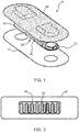
- Fig. 1 shows a known sensor patch 10, comprising a base layer 12, a flexible circuit board 20 and a top layer 30.
- the flexible circuit board 20 has two end pads 22, 24 which are interconnected by a meander section 26.
- the three layers shown are laminated together to form a sealed patch.
- Fig. 2 shows in simplified form a design of the bonding layer used in the lamination process for a sensor system in accordance with an example of the invention.
- the bonding layer 40 is to be provided over the flexible circuit board.
- the bonding layer 40 has an opening 42 over the meander section 26 so that the meander section is not constrained by the lamination process.
- Fig. 2 shows the meander section 26 beneath the bonding layer, seen through the opening 42, for clarity.
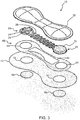
- Fig. 3 shows an example of wearable system, in exploded view.
- the wearable system comprises a base layer 12, a flexible circuit board 20, a top layer 30 and the bonding layer 40 with a meander opening 42.
- the bonding layer is beneath the flexible circuit board, namely between the flexible circuit board and the base layer. Bonding can additionally or alternatively be provided between the top layer and the flexible circuit board, again excluding the meander section. Thus, the bonding may be provided above and/or below the flexible circuit board.
- the flexible circuit board 20 comprises a first end pad 22 having a first contact area facing the base layer (and hence not seen in Fig. 4 ).
- the opposite side of the first contact area may in one example comprise a first circuit area, which for example provides connections to a battery 23.
- a second end pad 24 has a second contact area facing the base layer (again not seen in Fig. 3 ).
- the opposite side of the second contact area may in one example comprise a second circuit area, which for example provides connections to sensor processing circuitry and wireless transmission circuitry 25.
- This flexible circuit board may comprise a conventional polyimide flexible PCB, but it may also comprise screen-printed or inkjet-printed circuitry on a bendable polymer substrate such as polyethylene naphthalate (PEN) or polyethylene terephthalate (PET).
- PEN polyethylene naphthalate
- PET polyethylene terephthalate
- the meander section 26 is between the first and second end pads and it provides electrical connections between the circuitry carried by the end pads, as well as providing connections to and the contact areas of the end pads.
- the meander section preferably carries only interconnect tracks.
- the meander section preferably comprises an electrical connection between the first and second end pads.
- the flexible circuit board is for example a double-sided board, with contact areas facing the base layer which function as sensor input pads or actuator output pads, and electrical tracks facing the top layer which function as connection lines and contact pads for circuit components.
- the contact areas on the underside of the end pads are for making direct galvanic contact with the skin.
- the base layer 12 has openings 14 aligned with the contact areas, and the bonding layer 40 also has corresponding openings 44.
- gel contact electrodes 50 can be provided. These fit in the openings 14 and 44 so that skin contact pads extend beyond the plane of the base layer 12.
- the most basic design has two pads for contacting the skin of the subject, but there may be three or more pads, interconnected with each other by meander sections.
- the meander section is in a non-bonded region so that the stretching of the meander section is not inhibited by coupling to the top layer or base layer. In this way, there is increased freedom of deformation of the meander section.
- the meander section is preferably planar and defines an undulating track in that plane, for example a sequence of alternate U-bends as shown.
- other meandering paths may be formed, for example which overall follow a straight path or a curved path.
- the bonding layer may simply be around the outer edge of the overall wearable system outer housing, so that that openings 42, 44 are formed as a single opening.
- the bonding layer preferably surrounds or covers (from above or below) the end pads so that each end pad is formed into its own enclosure.
- the bonding layer preferably surrounds or covers (from above or below) the end pads so that each end pad is formed into its own enclosure.
- the meander opening may be a rectangle corresponding to the outer envelope shape of the meander section. However, other shapes may be used.
- the meander opening may fully surround the meander section 26 but there may be portions of the meander section which are covered by the bonding layer, such as the ends.
- Fig. 4 shows a variation to the design of the bonding layer 40.
- the end pads are each formed as a double circle to enable increased contact area.
- the circuitry may for example all be on one side of the flexible circuit board, facing downwardly.
- a central area 60 provides a connection to a non-flex printed circuit board.
- the meander opening 42 is formed as two sections 42a, 42b, one on each side of the central area 60.
- Fig. 5 shows a modification to the design of the bonding layer of Fig. 4 .
- the bonding layer 40 has contact anchors 70 within the meander openings 42a, 42b. These make connections between the top layer and base layer in the spaces between the meandering path of the circuit board. The overall structural unity of the system is improved but without constraining movement of the meander section.
- the bonding layer may be a hot-melt layer for thermal curing during lamination, such as a polyurethane film, or another adhesive for example using a silicone adhesive, a polyurethane adhesive or an acrylic adhesive. Adhesive foams may also be used.
- the top layer 30 is for example a foam structure, such as a thermoform foam structure. It has a shape to provide housing areas for the circuit components.
- the flexible circuit board 20 is for example a polyimide flexible foil (e.g. with thickness of tens of microns) with a copper conductor layer (e.g. also with thickness of ones or tens of microns).
- the base layer 12 comprises a liner of silicone or thermoplastic polyurethane.
- the contact electrodes 50 for example comprise screen printed silver chloride which are provided at the contact areas (at the bottom of the flexible circuit board). Contact electrodes may alternatively be provided using conductive adhesive.
- the wearable system for example comprises one (or more) sensor types from the list of:
- the wearable system may thus be used to determine one or more of various parameters such as heart rate, respiratory rate, heart rate variability, skin temperature, body posture, fall detection and activity level (such as a steps count).
- the wearable system is preferably battery operated, and a battery is provided on one of the circuit areas.
- a signal conditioning or processing circuit and wireless communications circuit are also provided on the circuit areas.
- There may also be memory storage, a display device.
- the invention applies to wearable sensors or actuators, and they may take the form of a patch or a textile.
- the invention is not limited to physiological sensory body systems. It can also be used for example for body motion sensing. In that case the wearable sensors will not measure a physiological body parameter, but will be in the form of a gyroscope or accelerometer which determines the movement of the body. Another option is non-sensory electronics in a shirt such as lights, stretchable displays, solar cells, heating, or even certain therapy options. The meander design can be used in all of these stretchable electronics cases.
- a computer program may be stored/distributed on a suitable medium, such as an optical storage medium or a solid-state medium supplied together with or as part of other hardware, but may also be distributed in other forms, such as via the Internet or other wired or wireless telecommunication systems. Any reference signs in the claims should not be construed as limiting the scope.
Landscapes
- Health & Medical Sciences (AREA)
- Life Sciences & Earth Sciences (AREA)
- Engineering & Computer Science (AREA)
- Animal Behavior & Ethology (AREA)
- Public Health (AREA)
- Pathology (AREA)
- Physics & Mathematics (AREA)
- Biomedical Technology (AREA)
- Heart & Thoracic Surgery (AREA)
- Medical Informatics (AREA)
- Molecular Biology (AREA)
- Surgery (AREA)
- Veterinary Medicine (AREA)
- General Health & Medical Sciences (AREA)
- Biophysics (AREA)
- Cardiology (AREA)
- Physiology (AREA)
- Psychiatry (AREA)
- Computer Networks & Wireless Communication (AREA)
- Psychology (AREA)
- Artificial Intelligence (AREA)
- Computer Vision & Pattern Recognition (AREA)
- Signal Processing (AREA)
- Chemical & Material Sciences (AREA)
- Dispersion Chemistry (AREA)
- Measuring And Recording Apparatus For Diagnosis (AREA)
- Measuring Pulse, Heart Rate, Blood Pressure Or Blood Flow (AREA)
Priority Applications (6)
| Application Number | Priority Date | Filing Date | Title |
|---|---|---|---|
| EP18176595.9A EP3578096A1 (de) | 2018-06-07 | 2018-06-07 | Wearable-vorrichtung |
| CN201980038430.3A CN112367904A (zh) | 2018-06-07 | 2019-05-28 | 可穿戴设备 |
| US16/972,365 US20210236036A1 (en) | 2018-06-07 | 2019-05-28 | A wearable device |
| JP2020568344A JP7285859B2 (ja) | 2018-06-07 | 2019-05-28 | ウェアラブルデバイス |
| EP19727004.4A EP3801198B1 (de) | 2018-06-07 | 2019-05-28 | Wearable-vorrichtung |
| PCT/EP2019/063709 WO2019233807A1 (en) | 2018-06-07 | 2019-05-28 | A wearable device |
Applications Claiming Priority (1)
| Application Number | Priority Date | Filing Date | Title |
|---|---|---|---|
| EP18176595.9A EP3578096A1 (de) | 2018-06-07 | 2018-06-07 | Wearable-vorrichtung |
Publications (1)
| Publication Number | Publication Date |
|---|---|
| EP3578096A1 true EP3578096A1 (de) | 2019-12-11 |
Family
ID=62597331
Family Applications (2)
| Application Number | Title | Priority Date | Filing Date |
|---|---|---|---|
| EP18176595.9A Withdrawn EP3578096A1 (de) | 2018-06-07 | 2018-06-07 | Wearable-vorrichtung |
| EP19727004.4A Active EP3801198B1 (de) | 2018-06-07 | 2019-05-28 | Wearable-vorrichtung |
Family Applications After (1)
| Application Number | Title | Priority Date | Filing Date |
|---|---|---|---|
| EP19727004.4A Active EP3801198B1 (de) | 2018-06-07 | 2019-05-28 | Wearable-vorrichtung |
Country Status (5)
| Country | Link |
|---|---|
| US (1) | US20210236036A1 (de) |
| EP (2) | EP3578096A1 (de) |
| JP (1) | JP7285859B2 (de) |
| CN (1) | CN112367904A (de) |
| WO (1) | WO2019233807A1 (de) |
Cited By (14)
| Publication number | Priority date | Publication date | Assignee | Title |
|---|---|---|---|---|
| USD917704S1 (en) | 2019-08-16 | 2021-04-27 | Masimo Corporation | Patient monitor |
| USD919094S1 (en) | 2019-08-16 | 2021-05-11 | Masimo Corporation | Blood pressure device |
| USD919100S1 (en) | 2019-08-16 | 2021-05-11 | Masimo Corporation | Holder for a patient monitor |
| USD921202S1 (en) | 2019-08-16 | 2021-06-01 | Masimo Corporation | Holder for a blood pressure device |
| WO2021118965A1 (en) * | 2019-12-12 | 2021-06-17 | Jabil Inc. | Health and vital signs monitoring patch with display and making of same |
| USD927699S1 (en) | 2019-10-18 | 2021-08-10 | Masimo Corporation | Electrode pad |
| USD933232S1 (en) | 2020-05-11 | 2021-10-12 | Masimo Corporation | Blood pressure monitor |
| US11478181B2 (en) | 2019-12-12 | 2022-10-25 | Jabil Inc. | Health and vital signs monitoring patch with display and making of same |
| US11576582B2 (en) | 2015-08-31 | 2023-02-14 | Masimo Corporation | Patient-worn wireless physiological sensor |
| USD979516S1 (en) | 2020-05-11 | 2023-02-28 | Masimo Corporation | Connector |
| US11637437B2 (en) | 2019-04-17 | 2023-04-25 | Masimo Corporation | Charging station for physiological monitoring device |
| USD985498S1 (en) | 2019-08-16 | 2023-05-09 | Masimo Corporation | Connector |
| GB2612835A (en) * | 2021-11-15 | 2023-05-17 | Occam Bio Ltd | A wearable sensor |
| US11980467B2 (en) | 2020-09-18 | 2024-05-14 | Jabil Inc. | Health and vital signs monitoring patch with display and making of same |
Families Citing this family (2)
| Publication number | Priority date | Publication date | Assignee | Title |
|---|---|---|---|---|
| USD940330S1 (en) * | 2019-06-10 | 2022-01-04 | Emfit Oy | Body sensor |
| GB2596124A (en) * | 2020-06-18 | 2021-12-22 | Prevayl Innovations Ltd | Contact pad assembly |
Citations (1)
| Publication number | Priority date | Publication date | Assignee | Title |
|---|---|---|---|---|
| US20180028071A1 (en) * | 2016-07-29 | 2018-02-01 | VivaLnk Inc. | Wearable patch for measuring temperature and electrical signals |
Family Cites Families (15)
| Publication number | Priority date | Publication date | Assignee | Title |
|---|---|---|---|---|
| US20080275327A1 (en) * | 2005-03-09 | 2008-11-06 | Susanne Holm Faarbaek | Three-Dimensional Adhesive Device Having a Microelectronic System Embedded Therein |
| EP3387991B1 (de) | 2010-05-12 | 2022-06-15 | Irhythm Technologies, Inc. | Gerätefunktionen und design-elemente für eine langzeithaftung |
| CA2837674A1 (en) * | 2011-05-31 | 2012-12-06 | Brown Shoe Company, Inc. | Footwear promoting natural motion |
| US9700222B2 (en) * | 2011-12-02 | 2017-07-11 | Lumiradx Uk Ltd | Health-monitor patch |
| WO2013181508A1 (en) | 2012-05-31 | 2013-12-05 | Zoll Medical Corporation | Long term wear multifunction biomedical electrode |
| CA2844379A1 (en) | 2013-03-15 | 2014-09-15 | Covidien Lp | Reduced motion artifact electrode |
| JP6606067B2 (ja) | 2013-06-06 | 2019-11-13 | トライコード ホールディングス,エル.エル.シー. | モジュール型生理学的モニタリング・システム、キット、および方法 |
| GB2521342B (en) | 2013-10-17 | 2016-08-03 | Monica Healthcare Ltd | Apparatus and method for detecting an abdominal electrophysiological signal |
| WO2016010990A2 (en) | 2014-07-15 | 2016-01-21 | Avery Dennison Corporation | Sensor devices and methods of applying a sensor device |
| US20160317057A1 (en) * | 2014-10-22 | 2016-11-03 | VivaLnk, Inc. | Compliant wearable patch capable of measuring electrical signals |
| US9378450B1 (en) * | 2014-12-05 | 2016-06-28 | Vivalnk, Inc | Stretchable electronic patch having a circuit layer undulating in the thickness direction |
| CN107949323B (zh) | 2015-09-11 | 2021-10-12 | 福田电子株式会社 | 生物信息测定装置 |
| CN205813737U (zh) * | 2016-06-13 | 2016-12-21 | 慈溪市桥头双对鞋厂 | 一种具有加热功能的鞋垫 |
| CN206366131U (zh) * | 2016-12-30 | 2017-08-01 | 苏州能斯达电子科技有限公司 | 一种监控脚部运动的智能穿戴设备 |
| CN207341282U (zh) * | 2017-10-09 | 2018-05-11 | 北京中科汇成科技有限公司 | 智能足底穿戴装置 |
-
2018
- 2018-06-07 EP EP18176595.9A patent/EP3578096A1/de not_active Withdrawn
-
2019
- 2019-05-28 JP JP2020568344A patent/JP7285859B2/ja active Active
- 2019-05-28 EP EP19727004.4A patent/EP3801198B1/de active Active
- 2019-05-28 US US16/972,365 patent/US20210236036A1/en active Pending
- 2019-05-28 WO PCT/EP2019/063709 patent/WO2019233807A1/en unknown
- 2019-05-28 CN CN201980038430.3A patent/CN112367904A/zh active Pending
Patent Citations (1)
| Publication number | Priority date | Publication date | Assignee | Title |
|---|---|---|---|---|
| US20180028071A1 (en) * | 2016-07-29 | 2018-02-01 | VivaLnk Inc. | Wearable patch for measuring temperature and electrical signals |
Non-Patent Citations (5)
| Title |
|---|
| RAJ M ET AL: "Soft bio-integrated systems for continuous health monitoring", VISUAL COMMUNICATIONS AND IMAGE PROCESSING; 20-1-2004 - 20-1-2004; SAN JOSE,, vol. 9083, 4 June 2014 (2014-06-04), pages 90831M - 90831M, XP060037124, ISBN: 978-1-62841-730-2, DOI: 10.1117/12.2051272 * |
| SEULKI LEE ET AL: "The Smart Patches and Wearable Band (W-Band) for comfortable sleep monitoring system", ENGINEERING IN MEDICINE AND BIOLOGY SOCIETY,EMBC, 2011 ANNUAL INTERNATIONAL CONFERENCE OF THE IEEE, IEEE, 30 August 2011 (2011-08-30), pages 6915 - 6918, XP032320308, ISBN: 978-1-4244-4121-1, DOI: 10.1109/IEMBS.2011.6091741 * |
| TRIPATHI RAGHUVENDRA PRATAP ET AL: "Design and fabrication of a nano patch electrode for ECG using CNT/PDMS", 2017 INTERNATIONAL CONFERENCE ON COMPUTING METHODOLOGIES AND COMMUNICATION (ICCMC), IEEE, 18 July 2017 (2017-07-18), pages 335 - 339, XP033315341, DOI: 10.1109/ICCMC.2017.8282703 * |
| VAN DEN BRAND JEROEN ET AL: "Flexible and stretchable electronics for wearable healthcare", 2014 44TH EUROPEAN SOLID STATE DEVICE RESEARCH CONFERENCE (ESSDERC), IEEE, 22 September 2014 (2014-09-22), pages 206 - 209, XP032677149, ISSN: 1930-8876, ISBN: 978-1-4799-4378-4, [retrieved on 20141105], DOI: 10.1109/ESSDERC.2014.6948796 * |
| WEI PINGHUNG ET AL: "A stretchable and flexible system for skin-mounted measurement of motion tracking and physiological signals", 2014 36TH ANNUAL INTERNATIONAL CONFERENCE OF THE IEEE ENGINEERING IN MEDICINE AND BIOLOGY SOCIETY, IEEE, 26 August 2014 (2014-08-26), pages 5772 - 5775, XP032674410, DOI: 10.1109/EMBC.2014.6944939 * |
Cited By (21)
| Publication number | Priority date | Publication date | Assignee | Title |
|---|---|---|---|---|
| US11576582B2 (en) | 2015-08-31 | 2023-02-14 | Masimo Corporation | Patient-worn wireless physiological sensor |
| US11701043B2 (en) | 2019-04-17 | 2023-07-18 | Masimo Corporation | Blood pressure monitor attachment assembly |
| US11678829B2 (en) | 2019-04-17 | 2023-06-20 | Masimo Corporation | Physiological monitoring device attachment assembly |
| US11637437B2 (en) | 2019-04-17 | 2023-04-25 | Masimo Corporation | Charging station for physiological monitoring device |
| USD919094S1 (en) | 2019-08-16 | 2021-05-11 | Masimo Corporation | Blood pressure device |
| USD919100S1 (en) | 2019-08-16 | 2021-05-11 | Masimo Corporation | Holder for a patient monitor |
| USD921202S1 (en) | 2019-08-16 | 2021-06-01 | Masimo Corporation | Holder for a blood pressure device |
| USD917704S1 (en) | 2019-08-16 | 2021-04-27 | Masimo Corporation | Patient monitor |
| USD933233S1 (en) | 2019-08-16 | 2021-10-12 | Masimo Corporation | Blood pressure device |
| USD933234S1 (en) | 2019-08-16 | 2021-10-12 | Masimo Corporation | Patient monitor |
| USD985498S1 (en) | 2019-08-16 | 2023-05-09 | Masimo Corporation | Connector |
| USD967433S1 (en) | 2019-08-16 | 2022-10-18 | Masimo Corporation | Patient monitor |
| USD927699S1 (en) | 2019-10-18 | 2021-08-10 | Masimo Corporation | Electrode pad |
| USD950738S1 (en) | 2019-10-18 | 2022-05-03 | Masimo Corporation | Electrode pad |
| US11478181B2 (en) | 2019-12-12 | 2022-10-25 | Jabil Inc. | Health and vital signs monitoring patch with display and making of same |
| WO2021118965A1 (en) * | 2019-12-12 | 2021-06-17 | Jabil Inc. | Health and vital signs monitoring patch with display and making of same |
| USD979516S1 (en) | 2020-05-11 | 2023-02-28 | Masimo Corporation | Connector |
| USD965789S1 (en) | 2020-05-11 | 2022-10-04 | Masimo Corporation | Blood pressure monitor |
| USD933232S1 (en) | 2020-05-11 | 2021-10-12 | Masimo Corporation | Blood pressure monitor |
| US11980467B2 (en) | 2020-09-18 | 2024-05-14 | Jabil Inc. | Health and vital signs monitoring patch with display and making of same |
| GB2612835A (en) * | 2021-11-15 | 2023-05-17 | Occam Bio Ltd | A wearable sensor |
Also Published As
| Publication number | Publication date |
|---|---|
| JP2021525616A (ja) | 2021-09-27 |
| EP3801198B1 (de) | 2023-08-16 |
| WO2019233807A1 (en) | 2019-12-12 |
| EP3801198A1 (de) | 2021-04-14 |
| US20210236036A1 (en) | 2021-08-05 |
| JP7285859B2 (ja) | 2023-06-02 |
| CN112367904A (zh) | 2021-02-12 |
Similar Documents
| Publication | Publication Date | Title |
|---|---|---|
| EP3801198B1 (de) | Wearable-vorrichtung | |
| US10918290B2 (en) | Multi-channel vitals device | |
| CN107960980B (zh) | 一次性生物计量贴片设备 | |
| US10285644B2 (en) | Patient worn sensor assembly | |
| US20080312524A1 (en) | Medical Sensor Having Electrodes and a Motion Sensor | |
| US20090022941A1 (en) | Self-adhesive element | |
| WO2012015479A2 (en) | Physiological status monitoring system | |
| CN108344524B (zh) | 一种用于测量温度及电信号的可穿戴贴片 | |
| JP7340600B2 (ja) | センサ、生体の深部温度を推定する方法、及びセンサを使用する方法 | |
| US20180028071A1 (en) | Wearable patch for measuring temperature and electrical signals | |
| CN112842392A (zh) | 一种可穿戴式的血压检测装置 | |
| GB2577726A (en) | Sensor system and method for continuous and wireless monitoring and analysis of heart sounds, circulatory effects and core temperature in organisms | |
| NO20181283A1 (en) | Sensor system and method for continuous and wireless monitoring and analysis of heart sounds, circulatory effects and core temperature in organisms | |
| GB2577725A (en) | Sensor system and method for continuous and wireless monitoring and analysis of respiratory sounds, heart rate and core temperature in organisms | |
| EP3860444B1 (de) | Sensorsystem und verfahren zur kontinuierlichen und drahtlosen überwachung und analyse von herzgeräuschen, kreislaufeffekten und kerntemperatur bei organismen | |
| CN111374649B (zh) | 生理感测装置、生理感测方法以及生理信息服务系统 | |
| CN215738891U (zh) | 一种体温检测垫 | |
| TW202045092A (zh) | 彈性可戴式感測器 | |
| CN114376542A (zh) | 生理参数采集结构及生理参数监测装置 | |
| CN115003226A (zh) | 可拉伸心电图(ecg)装置 |
Legal Events
| Date | Code | Title | Description |
|---|---|---|---|
| PUAI | Public reference made under article 153(3) epc to a published international application that has entered the european phase |
Free format text: ORIGINAL CODE: 0009012 |
|
| AK | Designated contracting states |
Kind code of ref document: A1 Designated state(s): AL AT BE BG CH CY CZ DE DK EE ES FI FR GB GR HR HU IE IS IT LI LT LU LV MC MK MT NL NO PL PT RO RS SE SI SK SM TR |
|
| AX | Request for extension of the european patent |
Extension state: BA ME |
|
| RAP1 | Party data changed (applicant data changed or rights of an application transferred) |
Owner name: KONINKLIJKE PHILIPS N.V. Owner name: NEDERLANDSE ORGANISATIE VOOR TOEGEPAST- NATUURWETENSCHAPPELIJK ONDERZOEK TNO |
|
| STAA | Information on the status of an ep patent application or granted ep patent |
Free format text: STATUS: THE APPLICATION IS DEEMED TO BE WITHDRAWN |
|
| 18D | Application deemed to be withdrawn |
Effective date: 20200613 |