EP3577472B1 - Vorrichtung und verfahren zum nachweis von gefährlich spannungsführenden objekten - Google Patents
Vorrichtung und verfahren zum nachweis von gefährlich spannungsführenden objekten Download PDFInfo
- Publication number
- EP3577472B1 EP3577472B1 EP18794631.4A EP18794631A EP3577472B1 EP 3577472 B1 EP3577472 B1 EP 3577472B1 EP 18794631 A EP18794631 A EP 18794631A EP 3577472 B1 EP3577472 B1 EP 3577472B1
- Authority
- EP
- European Patent Office
- Prior art keywords
- sensor
- signal
- sensor probes
- data
- probes
- Prior art date
- Legal status (The legal status is an assumption and is not a legal conclusion. Google has not performed a legal analysis and makes no representation as to the accuracy of the status listed.)
- Active
Links
Images


Classifications
-
- G—PHYSICS
- G08—SIGNALLING
- G08B—SIGNALLING OR CALLING SYSTEMS; ORDER TELEGRAPHS; ALARM SYSTEMS
- G08B21/00—Alarms responsive to a single specified undesired or abnormal condition and not otherwise provided for
- G08B21/18—Status alarms
-
- G—PHYSICS
- G01—MEASURING; TESTING
- G01R—MEASURING ELECTRIC VARIABLES; MEASURING MAGNETIC VARIABLES
- G01R29/00—Arrangements for measuring or indicating electric quantities not covered by groups G01R19/00 - G01R27/00
- G01R29/12—Measuring electrostatic fields or voltage-potential
-
- G—PHYSICS
- G01—MEASURING; TESTING
- G01R—MEASURING ELECTRIC VARIABLES; MEASURING MAGNETIC VARIABLES
- G01R29/00—Arrangements for measuring or indicating electric quantities not covered by groups G01R19/00 - G01R27/00
- G01R29/08—Measuring electromagnetic field characteristics
- G01R29/0807—Measuring electromagnetic field characteristics characterised by the application
- G01R29/0814—Field measurements related to measuring influence on or from apparatus, components or humans, e.g. in ESD, EMI, EMC, EMP testing, measuring radiation leakage; detecting presence of micro- or radiowave emitters; dosimetry; testing shielding; measurements related to lightning
- G01R29/0857—Dosimetry, i.e. measuring the time integral of radiation intensity; Level warning devices for personal safety use
-
- G—PHYSICS
- G01—MEASURING; TESTING
- G01R—MEASURING ELECTRIC VARIABLES; MEASURING MAGNETIC VARIABLES
- G01R29/00—Arrangements for measuring or indicating electric quantities not covered by groups G01R19/00 - G01R27/00
- G01R29/08—Measuring electromagnetic field characteristics
- G01R29/0864—Measuring electromagnetic field characteristics characterised by constructional or functional features
- G01R29/0871—Complete apparatus or systems; circuits, e.g. receivers or amplifiers
Definitions
- the present invention relates to the detection of electric fields, and more particularly, to apparatus and methods of detecting hazardously energized objects using the electric fields.
- stray voltages may present themselves when objects, such as manhole covers, gratings, street light poles, phone booths and the like become electrically energized (e.g., at 120V AC).
- An electrically conductive path may be established between underground secondary network cabling and these objects through physical damage to electrical insulation resulting in direct contact between electrically conductive elements or through the introduction of water acting as a conductor.
- a radiating object e.g., manhole cover or light pole
- a receiving "antenna” should be 11 ⁇ 2 to 2 wavelengths away from the emitting source (about 6,214 miles).
- Two wavelengths is the distance required for electric and magnetic fields to come into time phase and space quadrature where they behave as a plane wave.
- a detection system will typically be perhaps 10 ft. to 30 ft. away from the energized object, so that detection will take place in the extreme near field where electric and magnetic fields exist in a complex temporal and spatial pattern, not as a unified electromagnetic plane wave. Thus, electric and magnetic fields must be considered and measured separately.
- Techniques for the detection of stray voltages are typically carried out by manual inspection of surrounding electrical infrastructures for signs of leaking current.
- An inspection team equipped, for example, with hand held detection devices may be employed to make direct physical inspections of electrical infrastructures.
- inspectors using these detection devices are typically required to make contact with portions of electrical infrastructures, such as streetlamp bases or manhole covers, in order to obtain accurate measurements for determining the existence of potentially dangerous stray voltages.
- These manual inspections are undoubtedly time-consuming and give a false sense of security.
- document WO 2016/073020 describes a mobile apparatus mounted to a motor vehicle for detecting energized objects.
- the mobile apparatus includes two or more photonic sensors, mounted to the motor vehicle, and coupled to a photo-receiver, wherein the photo-receiver generates a signal corresponding to an electric field detected by the two or more photonic sensors, for narrowing down the location of a hazardously energized object.
- Document US 2009/195255 describes an apparatus for detecting an electrical field may that has at least one sensor probe for generating data corresponding to an electrical field detected by the at least one sensor probe, wherein the at least one sensor probe comprises at least one electrode.
- a processor, coupled to the at least one sensor probe is provided for analyzing the data to identify a voltage anomaly in the electric field.
- Document WO2006/071572 describes a sensor for sensing an electric field including a movable sensor probe.
- Document US 2006/139032 describes a method for sensing an electric field including processing digitized electric field signals, e.g., from an electric field sensing probe. The processing includes performing a Fast Fourier Transform of the digitized electric field signals to provide an indication of the magnitude of the electric field.
- Document US 2014/085095 describes a mobile apparatus for detecting an electric field produced by an object energized by a voltage anomaly having at least one sensor probe to detect the electric field and to provide a first signal corresponding to the detected electric field and a signal processor to filter the plurality of time domain samples according to a desired frequency.
- Document US 2011/184679 describes a method and apparatus for discriminating between electric field sources.
- a processor is coupled to a sensor probe, for processing data received from the sensor probe to generate a first field strength and at least a second field strength for determining whether the electric field source is potentially hazardous.
- Embodiments of the present invention generally relate to a method and apparatus for detecting and identifying hazardous objects in electric fields.
- an apparatus for detecting and identifying hazardous objects in electric fields according to claim 1 and a method for detecting and identifying hazardous objects in electric fields according to claim 8 are provided. Further features, aspects, details, and implementations are described in the detailed specification, the drawings, and the dependent claims.
- Embodiments of the present invention generally relate to apparatus and methods for detecting a stray voltage anomaly in an electric field. For purposes of clarity, and not by way of limitation, illustrative depictions of the present invention are described with references made to the above-identified drawing figures.
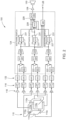
- FIG. 1 is a schematic diagram of an exemplary sensor system in accordance with some embodiments of the present invention.
- FIGS. 2 - 2A are schematic diagrams illustrating the operation of the sensor system employing digital electronic processing in accordance with some embodiments of the present invention. To best understand the invention the reader should refer to FIGS. 1 , 2 and 2A simultaneously.
- sensor system 100 generally comprises a detection system unit (DSU) 110, which may receive electric field measurements from one or more sensor probes, wherein each sensor probe comprises of at least one electrode.
- DSU detection system unit
- sensor probes 110x, 110y or 110z each may respectively comprise two electrodes 110x - 110x, 110y - 110y and 110z - 110z.
- the DSU 110 may employ any number of sensor probes for purposes of measuring an electric field in any particular area of interest being surveyed for stray voltage anomalies in electric fields, such as the embodiments discussed below with respect to FIGS. 3-5 and 7 - 8A .
- the DPS 112 comprises a multichannel analog-to-digital converter (ADC) 122, a digital signal processor (DSP) 124, a memory (EEPROM) 126, an audio amplifier 128, audible transducing device (speaker) 130, one or more data converters 132 (e.g., uni-directional or bidirectional SPI to RS-232 converters), and a source of electrical power, such as a power converter 134.
- the power converter 134 provides the various voltages for operating the DPS 112 and other electronic devices.
- electrical power for sensor system 100 may be obtained from any convenient electrical power source, such as the electrical system or battery 105 of the vehicle (e.g., truck) on or with which sensor system 100 is operated or a separate battery.
- the DPS 112 is coupled to the DSU 110 via an input (analog) section 114, which comprises low pass filters 116 and buffer amplifiers 120.
- the input section 114 comprises at least one (six shown) low pass filters 116, one for each electrode of sensor probes 110x, 110y, 110z, each preceded by an amplifier 118, and followed by a buffer amplifier 120.
- the amplifier 118 has a high input impedance and exhibits some gain.
- the low pass filter 116 cutoff frequency may be selected to minimize the effects of aliasing.
- a suitable low pass filter 116 may have a cutoff frequency (at -3 dB) of about 240 Hz and a -24 dB per octave slope.
- the low pass filter 116 supplies a rejection or attenuation of about 46 dB.
- a suitable ADC 122 may operate at a conversion burst rate of about 842 KSPS (kilo-samples per second). For example, every 1/960 th of a second the ADC 122 is commanded to perform 96 conversions, specifically 16 readings of each of six electrodes 110x - 110x , 110y - 110y , 110z - 110z. The readings converted by ADC 122 may be alternated such that temporal distortion effects are minimized. For example, ADC 122 converts plate electrode 1 (+ 110z) data, then plate electrode 2 (- 110z) data, and so on through plate electrode 6 (- 110x). It then repeats this six-conversion sequence 16 times for a total of 96 conversions.
- the data may be transferred into memory 126 from the ADC 122 via a serial link driven by a Direct Memory Access (DMA) function within the DSP 124.
- DMA Direct Memory Access
- differential data may be obtained from single ended data provided to the DSP 124 by the negation 221 of one of the pair of single ended data values and the summing 223 of one single ended data value with the negated data value.
- the single-ended signals from electrodes 110x - 110x , 110y - 110y , 110z - 110z may be coupled to the differential-to-single-end amplifiers 118 that provide balanced inputs with gain and convert the signal to single ended analog format to simplify subsequent processing, e.g., by lowpass filters 116.
- a multi-stage active low pass filter 116 then processes the signal to reduce signals other than the desired 60 Hz signal, i.e. to help separate the desired signal from near frequency interfering E-field signals.
- the signal is then further amplified and buffered and routed to ADC 122.
- the DSP 124 Upon completion of each 96 event burst conversion, as described above in reference to the operation of ADC 122, the DSP 124 averages the data to obtain six values (one for each of the six electrodes 110x - 11 0x, 110y - 110y, 110z - 110z), and stores the six values, e.g., in a single row of a 6 ⁇ 256 point matrix of a memory internal to DSP 124. This action is repeated 256 times until the entire matrix of the internal memory of DSP 124 is filled, at which point DSP 124 performs six Fast Fourier Transforms (FFTs) 224 on the six column vectors.
- FFTs Fast Fourier Transforms
- Each FFT 224 yields a frequency domain representation of the prior 256 samples (for each electrode 110x - 110x , 110y - 110y , 110z - 110z) in the form of 128 complex values.
- the 16 th FFT bin 226 contains the 60 Hz information, which is the only information that is of interest with respect to sensing stray 60 Hz voltages.
- differences between time domain values for the electrodes 110x - 110x , 110y - 110y , 110z - 110z are calculated, resulting in a 3 ⁇ 256 point matrix, which is then processed using the FFT 224 as described in the previous paragraph.
- measured field data from the sensor probes 110x, 110y, 110z is stored as measured ("raw" data), e.g., as six sets of data as produced by the electrodes 110x - 110x, 110y - 110y, 110z - 110z or as three sets of differential data as produced the three pair of probe electrodes 110x - 110x, 110y - 110y, 110z - 110z, or both.
- Data may be stored in a memory 126 of the DSP 124, or provided to a computer 136 or to any other device for storage and/or further analysis at the user's desire.
- Commands may be executed in response to the symbol (given at the left margin below) being entered via the keyboard of computer or by a point-and-click entry.
- Unrecognized characters generate a question mark "?” and an echo of that character to indicate that an invalid command has been entered.
- DSP 124 may further comprise a data streamer 240 which provides the unaveraged data independent of the settings of software switches 229, 231.
- Data provided by data streamer 240 e.g., in a SPI format, may be converted into another standard digital data format, e.g., into RS-232 format, by data converters 132.
- Data converters 132 may also convert data received in a given format, e.g., RS-232 format, into a format compatible with DSP 124, e.g., SPI format, as is the case for data provided by global positioning system (GPS) receiver 140.
- GPS receiver 140 may be any locating device capable of receiving signals from an antenna 142 broadcast by one or more GPS satellites orbiting the Earth to determine therefrom its location on the Earth.
- the detection alarm may produce a continuous output whose pitch is proportional to the field strength.
- the field strength values may be calculated at a rate far greater than the basic 3.75 Hz of the FFT data.
- the processing algorithm performs the 256-point FFT 224 on the most recent 256 samples collected (for each electrode 110x - 110x, 110y - 110y, 110z - 110z) as before, but to perform this operation at a 60 Hz rate.
- the large degree of time domain overlap from each FFT 224 to the next FFT 224 while using this process produces a far smoother output stream than is produced at the basic 3.75 Hz rate.
- the field strength values produced by the FFT 224 process range from about zero to about two million. Reasonable example frequencies audible to humans for this type of detection system would fall into a range between approximately 70 Hz and approximately 3 KHz.
- a half-step is defined as a 2 ⁇ ( 1/12) change in pitch, equivalent the difference between adjacent notes in the equal tempered chromatic scale commonly used in western music
- the pitch table used is based upon this amount of pitch change, so that discrete pitch changes would be perceived as a continuum by a human listener.
- an incremental pitch change in the audio output of the sensor system 100 results in a frequency change of +/-(1-2 ⁇ ( 1/96)), or +/-0.7246%.
- the effect of an apparently continuous pitch output is thus achieved from a discrete pitch system.
- NCO 232 comprises both a period register and a timer register.
- the timer register counts down to zero, it reloads from the period register and then counts down from the period value.
- the process described may only update the period register, thus avoiding the generation of transient pitch discontinuities that would sound to the ear as a "pop" or "crack.”
- the count register may be updated during high-to-low or low-to-high transitions of the audio output, thereby producing a continuous quasi-portamento output tone.
- the audio system e.g., audio amplifier 128 and speaker 130.
- the software of DSP 124 may be structured to support differential data when using the 60 Hz output data rate mode. Differential probe electrode data may be used to provide a higher signal-to-noise ratio compared to that of any single plate electrode.
- the user may be given the capability to select, e.g., setting software switches 229, 231, via the graphical user interface (GUI) 138 of computer 136, which of electrodes 110x - 110x, 110y - 110y, 110z - 110z to use to drive the system audio amplifier 128 and speaker 130, plus a fourth option, the average 228 of all three pairs.
- GUI graphical user interface
- the 60 Hz output data then controls a numerically controlled oscillator (NCO) 232 within DSP 124 for producing an audio pitch (tone) that is proportional to field strength.
- NCO numerically controlled oscillator
- the raw field strength data is converted to a logarithmic scale by DSP 124, which may be accomplished in any convenient manner, e.g., by means of a look-up table.
- the NCO 232 producing the audio output is the output of a timer-counter integral to the DSP 124 integrated circuit (IC).
- the DSP 124 sets the frequency of this timer-counter by writing to it a period value.
- the nominal DSP 124 clock (144 MHz, in one example) causes the timer-counter to count down from this period value to zero, at which point an output signal toggles state from high to low (or from low to high).
- the GPS location data provides a record of the location at which each detected stray voltage field was detected and the time thereof, as may be desired for subsequent analysis, e.g., for reviewing the location of a stray voltage anomaly and identifying the source thereof. Because the peak of the response to a source of stray voltage anomaly cannot be ascertained until after the vehicle has passed the source, the exact location of the source may not be observed until after the time at which it is detected, i.e. until after it is passed.
- the wheel speed sensor 144 may produce four signals, typically pulses, for each revolution of wheel W, wherein each signal represents about 16 inches (about 40-41 cm) of linear travel.
- Most manhole covers MHC are about 30-40 inches (about 0.75-1.0 m) in diameter, and so wheel speed indications every one to two feet (about 0.3 to 0.6 m) is sufficient to locate a manhole MHC cover having stray voltage thereon.
- wheel speed sensor 144 utilizes a Hall-effect sensor mounted so that the wheel lugs (studs and nuts) that secure wheel W to an axle pass close enough that the Hall-effect sensor produces a detectable output pulse therefrom.
- This may advantageously eliminate the need for a transmitted or other 60 Hz timing reference and, therefore, it may be disposed on and operated from a vehicle moving at a substantial speed, e.g., up to 15-25 miles per hour (about 24-40 km/hr), or faster.
- this allows processing of the sensed stray voltage data in essentially "real time" so as to facilitate an operator understanding and responding to the sensed data.
- the sensor system 100 may detect an energized manhole cover at a distance of about 15 feet (about 4.5 meters) when moving at speeds of up to about 10 mph (about 16 km/hr) or less, and consistently detect an energized light pole at a distance of about 25 feet (about 7.5 meters) when moving at speeds of up to about 20 mph (about 32 km/hr) or less.
- the sensor system 100 may additionally comprise an imaging system unit (ISU) 106, which may receive video input from one or more cameras.
- the ISU 106 may employ any number of cameras suitable for providing streaming images of a patrolled scene. Cameras employed may be video cameras, stereo cameras, various digital cameras, a combination of the aforementioned cameras or any other suitable camera and arrangement of cameras suitable for imagining a patrolled scene.
- one or more of cameras may be provided for imaging the environs where sensor system 100 is employed.
- sensor system 100 is deployed on a patrol vehicle or trailer
- two cameras may be provided thereon, wherein each camera is directed to view in a direction about 90° to the left of the direction of travel and 90° to the right of the direction of travel, so that images of what is present to the left and to the right of the patrolling vehicle are obtained.
- Video images therefrom may be recorded sensor system 100 traverses a patrolled environment.
- Video images may be obtained at a standard video rate, e.g., at 30 or 60 frames per second, but may be at much slower rates, e.g., one or two frames per second, consistent with the speeds at which the patrolling vehicle moves. For example, if a vehicle is moving at between 10 and 20 mph (about 14-28 feet per second or about 4.2-8.5 m/sec.), video at a two frames per second video rate would provide a new image for approximately each 14 feet (about 4.2 m) or less of travel, which should be sufficient to identify the location at which the stray voltage was detected.
- the video images may all be recorded (stored) or only selected images may be recorded.
- video images are stored in a video frame data buffer having a capacity to store a number of frames of video data for a set period of time. As each new frame is stored, the oldest previous frame is lost. Thus, the video data buffer contains video frames for the most recent period of time.
- a "frame grabber" card in the form of a PCMCIA card or an internal card, may be employed to synchronize electric field data sensed by DSU 110 with processed video data from ISU 106.
- the operator can cause the video images to be stored in a more permanent memory, or in another buffer, e.g., by activating a "Capture" function of computer 136, whereby the video of the scenes to the left and to the right of the vehicle over a thirty second period including the time at which the stray voltage was detected are stored and may be reviewed at the operator's convenience, e.g., either at that time or at a later time.
- Such storing action may be provided by inhibiting the video buffer from accepting additional frames of video data, thereby freezing the data then stored therein, or may be by transferring the data then stored in the video buffer to another memory device, such as the hard drive of computer 136 and/or a removable memory, e.g., a floppy disk, a CD ROM disk, a thumb drive, a memory card, a memory stick, or the like.
- a removable memory e.g., a floppy disk, a CD ROM disk, a thumb drive, a memory card, a memory stick, or the like.
- the audio tones produced by the sensor system 100 (and/or data representing the tones), the GPS location data, the wheel speed sensor 144 data, or a combination thereof, are stored so that the video images may be reviewed in synchronism with the detection tone (and/or data representing the tone) and the GPS location to allow a user/operator to more accurately locate where the stray voltage was detected.
- the GPS location information may be displayed and/or the audio tone may be reproduced, so that the operator can accurately locate the source of the stray voltage.
- Control thereof may by icons and other controls provided by a graphical user interface (GUI) 138 of computer 136, such as described below with respect to FIGS. 10 - 21 . Playback of the synchronized stored data may also be utilized for training personnel in operation of sensor system 100.
- GUI graphical user interface
- transceiver component 148 may be a BLUETOOTH TM enabled device, thereby providing a means for communicating stray voltage related information between sensor system 100 and a remote device, such as a personal digital assistants (PDAs), cellular phones, notebook and desktop computers, printers, digital cameras or any other suitable electronic device, via a secured short-range radio frequency.
- a utility member equipped with the remote device configured to receive the stray voltage related communication may be dispatched to a site determined to have a potential stray voltage anomaly for purposes of neutralizing the anomaly.
- the aforementioned are provided merely as exemplary means for wireless transmission of stray voltage related data. Other suitable wireless transmission and receiving means may be employed in the present invention.
- the computer 136 or other suitable computing system may provide a GUI 138 for an operator to control the operation of sensor system 100, particularly measurement and processing components associated with DSU 110, and to monitor electric field data as measured. For example, an operator may adjust the values of the constants and scaling factors utilized in the detection and averaging processing for producing an audible alarm (described in detail below).
- the computer 136 may also provide a convenient means for storing a record or log of the measured field and location (GPS) data for subsequent review and/or analysis, as might be desired for determining when and where a stray voltage anomaly existed.
- GPS measured field and location
- GUI 138 receives data, directly or indirectly, from various components described in conjunction with sensor system 100 and, accordingly, displays them to the operator for purposes of controlling and monitoring the detection of stray voltage anomalies present in patrolled areas.
- GUI 138 may be a video based interface having a video display. The data provided to GUI 138 provides the interface operator with an opportunity to visually monitor and analyze incoming data measured by a stray voltage detection system on the video display.
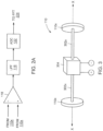
- FIG. 3 is a schematic diagram of a DSU 110 in accordance with some embodiments of the present invention.
- the DSU 110 may use a differential sensor.
- DSU 110 may comprise two spaced-apart metalized plate electrodes 110x - 110x (electrode pair 110x), separated by an insulating structure 302x.
- the insulating structure 302x may be rigid so that vibration or other physical motion of the DSU 110 while in the presence of static and low frequency fields does not cause spurious output in the 60 Hz frequency region.
- the electrodes 110x - 110x may be connected to an amplifier 304.
- the amplifier 304 is a high input impedance amplifier (e.g., about 60 Tera-ohms). Sensitivity of the DSU 110 is a function of the size and separation of the plate electrodes.
- the efficiency and sensitivity of the DSU 110 may be negatively affected by interference from other electric fields. Interfering electric fields may be produced by other electrified devices, such as storefront signs, electronic devices, or the like. In addition, as people move about, e.g., as pedestrians, they tend to generate electric charges on their clothing. These interfering background electric fields caused by the electric charges associated with people typically occur in the DC to 20 Hz frequency range. The aforementioned potentially interfering electric fields may produce charges that can induce a voltage on the electrodes 110x - 110x of the DSU 110, thus reducing the sensitivity of the DSU 110.
- This problem may be mitigated by employing feedback in the amplifier 304 (i.e., the differential pre-amplifier discussed above) that reduces its sensitivity to low frequency fields without reducing the very high input impedance at 60 Hz that helps give the sensor system 100 its high sensitivity to 60 Hz fields.
- feedback in the amplifier 304 i.e., the differential pre-amplifier discussed above
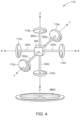
- FIG. 4 is a schematic diagram of a three-axis (tri-axial) DSU 110 in accordance with some embodiments of the present invention.
- a three axis arrangement may be employed to make X, Y and Z-axis electric field measurements simultaneously.
- the DSU 110 depicted schematically in relation to a manhole cover MHC, comprises three pairs of spaced apart electrodes 110x - 110x, 110y - 110y, 110z - 110z (electrode pairs 110x, 110y, 110z), of the sort shown in FIG. 2 arranged in three mutually orthogonal directions and each supported by an insulating structure 302x, 302y, 302z.
- a high input impedance amplifier 304 may be associated with each pair of electrodes, and may be embodied in any arrangement of differential circuitry, of single ended circuitry, or a combination thereof, as may be convenient.
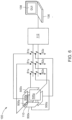
- FIG. 5 is a schematic diagram of DSU 110 in accordance with some embodiments of the present invention.
- DSU 110 may further comprise at least one pair (three shown) of electrically conductive auxiliary electrodes 500x - 500x, 500y - 500y, 500z - 500z (auxiliary electrode pairs 500x, 500y, 500z) in addition to the electrode pairs 110x, 110y, 110z.
- the auxiliary electrode pairs 500x, 500y, 500z may be supported in a similar manner as the electrode pairs 110x, 110y, 110z as described above.
- auxiliary electrodes 500x - 500x, 500y - 500y, 500z - 500z may be planar and disposed generally parallel to each other and outboard of electrode pairs 110x, 110y, 110z (further from the center of DSU 110) along their respective axis.
- the auxiliary electrodes 500x - 500x, 500y - 500y, 500z - 500z may be any shape or size suitable to allow for accurate measurements.
- the auxiliary electrodes 500x - 500x, 500y - 500y, 500z - 500z may be smaller, the same size, or larger than the electrodes 110x - 110x, 110y - 110y, 110z - 110z.
- the auxiliary electrodes 500x - 500x, 500y - 500y, 500z - 500z are about two times the size of electrodes 110x - 110x, 110y - 110y, 110z - 110z, and may be disposed to define a cube that is about two times as large as that of a cube defined by the electrode pairs 110x, 110y, 110z.
- auxiliary electrodes 500x - 500x, 500y - 500y, 500z - 500z may be positioned generally parallel to electrodes 110x - 110x, 110y - 110y, 110z - 110z, respectively.
- the electrode pairs 500x, 500y, 500z are electrically floating, i.e. they are not electrically connected to any of electrode pairs 110x , 110y , 110z , or to DSU 110 or sensor system 100.
- auxiliary electrode pairs 500x, 500y, 500z may alter the electric field, but do not unacceptably affect the sensing thereof by electrode pairs 110x, 110y, 110z.
- auxiliary electrodes 500x - 500x, 500y - 500y, 500z - 500z are connected to one or more other auxiliary electrodes 500x - 500x, 500y - 500y, 500z - 500z.
- One such connection is to make an electrical connection between the auxiliary electrode pairs 500x, 500y, 500z that are on the same axis.
- the auxiliary electrodes 500z - 500z which are spaced apart along the Z (or vertical) axis, may be connected together while making lateral (i.e. fore-aft and left-right) field measurements.
- auxiliary electrodes 500z - 500z vertically oriented fields, or at least primarily vertically oriented fields, from overhead sources are kept from leaking into or causing signal output on the X and Y axis electrode pairs 110x, 110y, or at least the effect of such vertically oriented fields on the X and Y axis electrode pairs 110x, 110y is substantially reduced.
- the pair of auxiliary electrodes 500z may be connected to a reference point, or to a ground, if available.
- any auxiliary electrode pair 500x, 500y, 500z may be connected together to similarly alter directional sensitivity.
- auxiliary electrodes 500x and 500y when a high voltage source is alongside, as where high tension electrical power distribution equipment is nearby and close to ground level, the two pair of auxiliary electrodes 500x and 500y, which are spaced apart along the X and Y (or lateral) axes, may be respectively connected together while making vertical (i.e. Z axis) field measurements.
- Z axis vertical
- auxiliary electrodes 500x, 500y may be connected to a reference point, or to a ground, if available.
- any two pair of auxiliary electrodes 500x, 500y, 500z may be connected together to similarly increasing directional sensitivity.
- auxiliary electrodes 500x - 500x, 500y - 500y, 500z - 500z may be selectively connectable to each other by switches S1x, S1y, S1z, respectively.
- the switches S1x, S1y, and S1z are sufficient to provide the desired respective selectable switching function for auxiliary electrode pairs 500x, 500y, 500z so as to enable the selective directing of the sensitivity of the electrode pairs 500x, 500y, 500z, respectively.
- Control of switches S1x, S1y, S1z may be effected using computer 136 via DPS 112, by activating respective toggle-type commands using GUI 138 of computer 136, although other control arrangements may be employed.
- any electrode pairs 110x, 110y, 110z utilized may be connected to a common reference point, which could be ground, if a ground is available, or could be a power supply line or a power supply common line or could be a vehicle structure.
- the common reference may be any reference point that is likely to be relatively fixed in potential relative to the potentials utilized by sensor system 100.
- auxiliary electrodes 500x - 500x, 500y - 500y, 500z - 500z such is not necessary.
- any number of pairs of auxiliary electrodes that is less than or equal to the number of pairs of electrodes may provide a useful arrangement, and a greater number of auxiliary electrodes could be provided.
- FIG. 7 is a schematic diagram of a tri-axial DSU 110 mounted in a radar dome (radome) arrangement in accordance with some embodiments of the present invention.
- the electrodes 110x - 110x , 110y - 110y , 110z - 110z may be positioned as if on the six surfaces of a cube, or may be supported by a cube - like structure 702.
- the cube - like structure may be additionally supported by a support structure 704.
- the cube - like structure 702 and support structure 704 may be constructed of any suitable material that would provide structural support and not interfere mechanically or electrically with the DSU 110.
- the cube - like structure 702 or support structure 704 may comprise an insulating material, a dielectric plastic (e.g. PVC), Styrofoam TM , urethane foam, wood, plywood, or the like.
- the support structure 704 may be employed to suspend the cube a sufficient distance from the vehicle carrying the DSU 110 or the ground surface so that the effects of movement of the cube, e.g., due to vehicle movement, surface (pavement) irregularities, vehicle suspension motion, and/or cube support movement, is relatively small relative to the distance from the vehicle and from the ground.
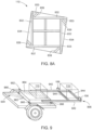
- FIGS. 8 - 8A are schematic diagrams of an isometric view and a top view of a tri-axial DSU 110 mounted in a radome arrangement in accordance with some embodiments of the present invention.
- DSU 110 comprises four sides 832 joined at corners of a cube.
- Each of sides 832 is trapezoidal in shape comprising a square portion defining one side of a cube and a contiguous triangular portion 833 that serves as a stiffening member in conjunction with base 834 to which sides 832 are fastened.
- Base 834 is a square having a side length substantially the tip-to-tip dimension of adjacent sides 832, with the tips at the corners of base 834.
- a square top 838 is fastened to sides 832.
- DSU 110 Internal to DSU 110 are a pair of substantially rectangular stiffeners 836 that intersect substantially perpendicularly and are fastened at the mid-lines of respective sides 832, and to base 834 and top 838. Additional stiffeners 839 may be provided at the corners of DSU 110 at an angle inside the corners defined by stiffeners 833 and their respective adjacent sides 832.
- high input impedance amplifiers (not shown) associated with the three pairs of electrodes 110x - 110x, 110y - 110y, 110z - 110z may be disposed within the cube defined by electrodes 110x - 110x , 110y - 110y , 110z - 110z.
- electrodes 110x - 110x , 110y - 110y , 110z - 110z have been described above, other non-cubical arrangements may be employed, e.g., a rectangular solid or a spherical arrangement.
- electrodes 110x - 110x , 110y - 110y , 110z - 110z are shown, electrodes 110x - 110x, 110y - 110y, 110z - 110z may be circular or rectangular or hexagonal or any other suitable shape.
- the DSU 110 may be mounted on a support frame base 902 that is mounted to a vehicle, such as directly to a car or truck, or to a wheeled trailer 904 capable of being towed by a vehicle.
- the support frame base 902 may be constructed of any suitable material that would provide structural support and not interfere mechanically or electrically with the DSU 110, such as an insulating material, a dielectric plastic (e.g. PVC), wood, plywood, or the like.
- the support frame base 902 may be constructed of wood to provide for a rigid structure, while also providing damping so that resonances near 60 Hz may be avoided.
- other insulating materials may be employed consistently with the high-input impedance of differential pre-amplifiers for electrodes 110x - 110x , 110y - 110y, 110z - 110z.
- the support frame base 902 may comprise a compartmented frame 962 having a top and bottom faces which can be filled with ballast.
- the compartmented frame 962 may be filled with a sufficient amount of ballast to approach the load weight limit for the trailer 904, e.g., about 100 pounds below the weight limit, so as to reduce the natural frequency of the trailer 904 and its suspension.
- support frame base 902 is mounted to the bed of trailer 904 by four optional vibration isolators 966 located respectively at each of the four corners of support frame base 902 so as to reduce the natural frequency well below 60 Hz, e.g., to about 12.5 Hz.
- support frame base 902 is mounted directly to the bed of trailer 904 and DSU 110 is cantilevered behind trailer 904 on a support structure 906 comprising at least one outrigger (two shown) 942 that extend rearward so that DSU 110 is positioned behind the trailer 904.
- DSU 110 may be positioned sufficiently enough away from the trailer 904 as to eliminate or reduce interference from metal surfaces or electrical sources on the trailer 904.
- DSU 110 is positioned from about 0.9 to about 1.6 meters (about 3 to about 5 feet) from the from the rear of support frame base 902 and trailer 904, and about 0.9 to about 1.6 meters (about 3 to about 5 feet) above the ground (e.g., pavement).
- Outriggers 942 may further comprise at least one (two shown) transverse members 944 to provide additional strength. Rearward portions of trailer 904, such as the rear cross member, may be removed to further separate DSU 110 from metal that could distort the field being sensed.
- either fixed outriggers or telescoping or other form of collapsible outrigger or extension could be employed so that the DSU 110, may be moved closer to the vehicle (i.e. stowed) for transit and farther from the vehicle (i.e. deployed) for operation to facilitate adjusting the sensitivity of DSU 110.
- vehicle-borne sensor system 100 While a vehicle-borne sensor system 100 is described, it is contemplated that apparatus employing the arrangements and methods described herein may be provided in a case or backpack that could be carried by a person.
- computer 136 may be a personal digital assistant or other small device.
- FIGS. 10-21 illustrate exemplary displays that may be provided on video display of GUI 138 for monitoring and controlling the operation of sensor system 100, in accordance with some embodiments of the present invention. To best understand the invention, the reader should refer to FIGS. 10-21 simultaneously.
- GUI 138 may be provided on a computer 136.
- a computer program for providing GUI 138 will initialize a main display 1000, as illustrated in FIG. 10 .
- the GUI 138 may run on a computer 136 running any suitable operating system, such as Microsoft Windows ® , Linux ® , Ms-Dos ® , Mac Os ® , or the like, for providing visual or audible information regarding the sensing of stray voltage anomalies in an electric field relative to a user selected manual threshold value or an automatically determined threshold value.
- Run command option 1006 when selected, will prompt for information to be entered in an initial identification screen.
- the initial identification screen may be, for example, system login display 1100 of FIG. 11 .
- System login display 1100 may request an the interface operator to provide a username in field 1102, a patrol vehicle name in field 1104 and a patrol vehicle number in field 1106 for purposes of authorizing access to the operational and monitoring controls of sensor system 100.
- the interface operator may then select login command option 1108 to proceed with system verification of authorized access to sensor system 100.
- the interface operator may select cancel command option 1110 to terminate login procedures for sensor system 100.
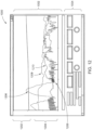
- main display 1000 Upon a successful login at display 1100, data sampling is initiated and main display 1000 is populated with sensor data, as illustrated in the main display 1000 of FIG. 12 .
- Sensor data is provided on video display 1002, which may be provided in a split screen format for displaying multiple video image frames (one from each camera).
- Multiple split screen views 1202, 1204 may display video image frames received from one or more cameras contained in the ISU 106.
- a patrol vehicle may be equipped with two cameras positioned on opposing sides for providing corresponding video image frames from both sides of the patrol vehicles path of travel.
- main display 1000 of FIG. 12 is shown with two split screens 1202 and 1204, additional split screens may be incorporated into video display 1002 to facilitate the utilization of more than two cameras.
- Control panel 1004 of main display 1000 provides the interface operator with a plurality of monitoring and control options.
- Control panel 1004 may include a system monitor indicator 1302, an audio threshold indicator 1304 and an audio snooze indicator 1306.
- a clear command option 1308, a suspend command option 1310, a preferences command option 1312, an event capture command option 1314 and a stop command option 1316 are provided to the interface operator in control panel 1004.
- Control panel 1004 may also provide information in a latitude display 1318, a longitude display 1319, an address display 1320, a signal strength display 1322, a speed display 1324 and a time stamp display 1326.
- Indicators 1302, 1304 and 1306 may be visual indicators, configured to change color or blink upon satisfaction of preprogrammed criteria.
- System monitor indicator 1302 may be a green color when operating within system specifications.
- system monitor indicator 1302 may turn yellow to notify the interface operator that there exists a problem, such as, lack of a GPS signal. In this case, no latitude, longitude or address information may be shown, respectively, in displays 1318, 1319 and 1320.
- Another potential trigger indicative of a problem is lack of video or electric field measurement data, wherein there would be no video image frame or measurement readings on video display 1002.
- Other potential problems that may trigger indicator 1302 may be depleted disk space for recording captured events (described in detail below) or loss of communication between DPS 112 and GUI 138.
- the interface operator may adjust the default threshold settings provided in connection with the audible notification tone if an excess amount of background noise interferes with accurate or efficient notifications.
- preferences command option 1312 provided on control panel 1004
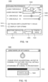
- the interface operator could be provided with a preferences display 1400, as illustrated in FIG. 14 , for modifying values associated with the audible tone.
- the interface operator could raise the threshold value, using audio threshold increase button 1402 and decrease button 1404, to minimize or eliminate false audible tones being generated due to a noisy environment in a patrolled environment.
- Any changes made to the default audible threshold value in preferences display 1400 may be represented by audible threshold indicator 1304 on control panel 1004 turning yellow. The change in color informs the interface operator that the audible notification tone is operating according to user defined values, not system defined default values.
- Toggle switches 1408 and 1410 permit the interface operator to adjust, respectively, the scale used in x-axis 1002x, which measures in feet the distance traveled since the last event capture, and y-axis 1002y, which measures in decibels the electric field signal strength, on video display 1002.
- Trace option 1414 when selected, allows for the logarithmic scaling of all y-axis 1002 values in order to ensure that values are easily readable and that entire plot lines appear within video display 1002 of main display 1000.
- DSP string option 1416 may be provided as a means for displaying processing related data, when selected, to troubleshooting sensor system 100.
- streaming synchronized data of the electric field strength overlaid on the corresponding video frames of the scene being traversed at the time of measurement may be displayed to the interface operator on video display 1002 of main display 1000.
- corresponding latitude and longitude information related to the patrolling vehicle is received by GPS receiver 142 and provided, respectively, to display fields 1318 and 1319.
- An address corresponding to the latitude and longitude readings provided in display fields 1318 and 1319 may also be provided in display field 1320.
- a signal strength value may be provided in display field 1322.
- the speed of the patrol vehicle may be presented in display field 1324, along with a current data and time stamp in display field 1326.
- the interface operator may temporarily suspend data sampling at any time by selecting a suspend command option 1310, clear received data by selecting a clear command option 1308 or exit GUI 138 system entirely by selecting a stop command option 1316 provided on control panel 1004 of main display 1000.
- variable-pitch alert that is configured for alerting the interface operator of detected fluctuations and/or spikes in measured electric field readings that exceed a defined threshold. Therefore, when a potential anomaly is detected, represented for example by a rise-peak-fall in the alert pitch, a corresponding visual spike in raw voltage plot 1206, a high signal strength value in signal strength display field 1322 or a combination thereof, interface operator may select an event capture command option 1314 for purposes of gathering additional information to review the potentially detected stray voltage anomaly.
- Data collection display 1500 prompts the interface operator to continue driving the patrol vehicle for a predefined distance (e.g., an additional 40 feet after selection of event capture command option 1314) in order to collect enough data sampling information to fully analyze the background noise associated with the captured event.
- a progress bar 1502 may be provided in display 1500 to inform the interface user of the remaining distance of travel required. Upon completion of the additional information collection process, represented by progress bar 1502, the interface operator may stop the collection of streaming data by GUI 138 and proceed to event capture display 1600 for analyzing the captured event.
- the collection of streaming data may be stopped or paused by stopping the patrol vehicle.
- collection of additional information pertaining to the captured event may be optionally terminated earlier, through selection of a cancel command option 1504, to permit the interface operator to proceed to review the captured event on event capture display 1600 without collection of additional information.
- Event capture display 1600 allows the interface operator to more closely examine potentially detected anomalies by providing playback analysis of the captured event. More specifically, the interface operator may compare raw voltage plot 1206 and adaptive threshold plot 1208 to assist in identifying the object displayed in the corresponding image frame that is most likely to be the source of the anomaly. In event capture display 1600, the three plot lines may be aligned to permit the interface operator to look for points where smoothed plot 1210 exceeds adaptive threshold plot 1208. This indicates that there exists a spike above the averaged background noise and, therefore, the existence of an anomaly.
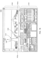
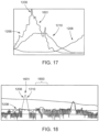
- Enlarged views of a detected stray voltage anomaly as it may be provided on video display 1602 of event capture display 1600 of FIG. 16 is illustrated in conjunction with FIGS. 17-18 .
- pinpoint indicator 1601 is positioned near the peak of spike in raw voltage plot 1206. All related sensor data related to this particular position is provided to the interface operator on playback control panel 1604. As can be seen near the spike in raw voltage plot 1206, smoothed plot 1210 exceeds adaptive threshold plot 1208, indicative of a potentially dangerous anomaly in the captured scene.
- pinpoint indicator 1601 is positioned over the peak of a spike, the object most centered in a video frame on video display 1602 is likely the source of the detected anomaly.
- the video image frame shown on video display 1602 of event capture display 1600 may be provided, wherein it can be seen that an object 1800 most centered in the video frame is likely the source of the detected anomaly.
- the video image frame may be isolated and enlarged by selecting a full screen command option 1906 (described below with respect to FIG. 19 ) from playback control panel 1604.
- Event capture control panel 1604 is comprised of a play command option 1902, a pause command option 1904, a full screen command option 1906, a preferences option 1908 and a main display option 1910.
- Play command option 1902 may allow the interface operator to play a video clip selected from a saved events section 1916.
- pause command option 1904 may allow the interface operator to pause playback of the video clip selected from saved events section 1916.
- Full screen command option 1906 may allow the interface operator to toggle between full-sized video images and regular-sized video images provided.
- Preferences command option 1908 may provide the interface operator with additional playback and review options not shown on playback control panel 1604.
- command option 1908 when selected, may provide preferences related to wireless communication of captured events to dispatch a remote crew.
- Main display option 1910 may allow the interface operator to return to main display 1000.
- a disable plotting option 1912 may also be provided, wherein the plots may be removed for a clearer view of scene objects displayed on video display 1002 when option 1912 is selected.
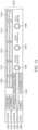
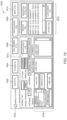
- FIG. 20 provides an enlarged view of objects section 1918.
- An environmental object or infrastructure name may be listed in a predefined objects scroll menu 2002 or may be defined by the interface operator using an object identification field 2004.
- the interface operator may then add the object identified in predefined objects scroll menu 2002 or object identification field 2004 to a selected object field 2008 using, respectively, an add command option 2006 or an add command option 2003.
- An added object identified in selected object field 2008 may also be removed by selecting a remove command option 2007. Additional notes, comments and instructions may be provided by the interface operator using a comments field 2010.
- GUI 138 is configured so that if multiple objects are determined to be present in a scene where an anomaly was detected, the interface operator may identify the multiple objects in selected object field 2008.
- the interface operator may then select a save event command option 1914 to record the identified object source of the anomaly, associated comments regarding the anomaly and anomaly location information for future reference and analysis of the captured anomaly event in the saved event section 1916. Thereafter, the interface operator may return to main display 1000, via command option 1910, and restart movement of the patrol vehicle to restart data sampling of the scene being traversed.
- Information that has been populated, for example, into objects section 1918 may be edited. For instance, if it is determined that an object previously identified as the source of a stray voltage anomaly is not indeed the source of the anomaly, selected objects field 2008 may be edited using commands 2006 and 2007 to, respectively, add a new source and remove the inaccurate source. Once changes have been made, the interface operator may select an update command option 2106 to have the new information saved in connection with the previously saved event.
- GUI 138 may be configured to generate a database entry for the saved event and create separate files for video and corresponding sensor related data.
- GUI 138 may be configured to create an AVI file for storing video images and an XML file for storing all other sensor related data. These files may be saved on a hard disk (e.g., memory component) and retrieved when the corresponding event is selected and loaded using playback control panel 1604 on event capture display 1600. If it is determined that saved events are no longer needed or have been archived elsewhere, or alternatively, if additional storage space is needed, the interface operator may delete using command options 2108 and 2110 provided on saved events section 1916 of playback control panel 1604.
- GUI 138 of sensor system 100 for monitoring and controlling the detection of a stray voltage anomaly is described with reference to the flowchart of FIG. 22 .
- the monitoring of streaming data displayed on video display 1002 of GUI 138 is initiated, at step 2202 , by providing user login information at step 2204. If the login information provided at display 1100 of FIG. 11 is determined to be for an authorized user, then GUI 138 may begin to sample data and provide a visual output of streaming data, at step 2208, on main display 1000, which may be driven by movement of the patrol vehicle equipped with sensor system 100.
- GUI 138 of sensor system 100 may audibly, via a variable-pitched alert tone, and visually, via a spike in plots provided on graphical video display 1002, prompt the interface operator upon detection of a stray voltage anomaly at step 2210.
- interface operator may decide to capture the event by selecting event capture command option 1314 provided on control panel 1004 of main display 1000 at 2214.
- additional processing may be executed to collect additional information about the captured event and an additional alert notification may be provided to the interface operator at 2216, indicating to the interface operator that the subsequent processing of the captured event is likely a stray voltage anomaly.
- Playback controls are provided to the interface operator, at step 2218, via control panel 1604 on event capture display 1600 of FIG. 16 .
- the interface operator may record the event at step 2220.
- the interface operator may elect to resume data sampling of the area being patrolled at 2224, thereby reinitiating the receipt of streaming data at main display 1000.
- GUI 138 may go into a standby mode, at step 2226, if no action is taken after a predetermined amount of time or, alternatively, if the interface operator elects to suspend data sampling by selecting, e.g., suspend command option 1310 on control panel 1004 of main display 1000.
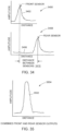
- FIGS. 23 and 23A are graphical representations of a theoretical electric field profile and a measured electric field profile, respectively.
- the abscissa thereof represents distance x (in arbitrary units) and the ordinate thereof represents normalized electric field as a function of distance F(x).
- the output signal from DSU 110 described herein may contain a considerable amount of noise due to detection of background 60 Hz electric field. Due to the motion of DSU 110 in this background field, the amplitude of the background noise signal produced thereby is constantly changing, even when the strength of the background electric field is constant. Further, movement of the DSU 110 in any electric field (even a static field, such as one generated by the air flow over the surface of a vehicle tire) results in modulation of such field and, in general, in the generation of a phantom 60 Hz signal. Under such circumstances, discriminating between a legitimate stray voltage electric field and background noise becomes difficult and requires prolonged training of the operator, combined with a high level of operator concentration during the operation of the equipment.
- a method for automatically discriminating between a legitimate stray voltage signal and background noise can supplement the processing and reduce the stress imposed on the operator.
- Normalization in time is accomplished by varying the rate at which the Fast Fourier Transform (FFT) of the sensed electric field is re-performed as a function of the lateral speed of the DSU 110, e.g., the speed of the vehicle on which DSU 110 is mounted.
- Normalization in amplitude is accomplished by observing the ratio between the amplitude of a fresh sample of the sensed electric field and a running average from the amplitudes of all past samples thereof.
- FFT Fast Fourier Transform
- normalization in time is accomplished by varying the frequency at which the FFT is performed, such as performing one FFT per unit of travel of the DSU 110.
- one FFT could be performed per every unit of distance (e.g., a foot or meter) of travel, e.g., as measured by the wheel speed sensor 144 sensing wheel 146 rotation or by a distance measuring wheel.
- the time period between FFT sampling should be rounded such as to be an integer multiple of the period of the monitored electric field signal (in this example, an integer multiple of 1/60 sec. for a 60 Hz signal).
- a running average is difficult to calculate on a sample with an open ended number of data points, and calculating an average from the last N samples may not be satisfactory unless the number N is very large, which can impose undue demands on DSP 124 and memory 126.
- Method 2400 starts at 2402 with an initialization 2404 of time t, an average, represented by FLOAT(t), and the alarm value ALARM.
- time t thereafter (referred to as a "fresh time"), the time value or sample rate is updated 2406 by an increment value S that is related to speed, e.g., the output of wheel speed sensor 144.
- the interval S may correspond to a 1 ⁇ 4 revolution of wheel 146, e.g., four detections per wheel revolution.
- the processing interval may be thought of as being fixed in space, rather than in time. This variable time interval implements the processing of sensed voltage data as a function of the speed of sensor system 100 to produce signals of the sort illustrated in FIGS. 23 and 23A .
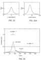
- FIG. 25 is a graphical presentation of an example of data produced by the method 2400 described in relation to FIG. 24 .
- the abscissa represents units of time t (or of distance) whereas the ordinate represents units of amplitude.
- Data points SIG 60 (t) represent the value of electric field sensed by DSU 110 versus time t as the sensor system 100 moves along a path.
- SIG 60 (t) exhibits a peak in the stray voltage in the region of values of about 60-100, and relatively low values both before and after the peak.
- the term "about” means that dimensions, sizes, formulations, parameters, shapes and other quantities and characteristics are not and need not be exact, but may be approximate and/or larger or smaller, as desired, reflecting tolerances, conversion factors, rounding off, measurement error and the like, and other factors known to those of skill in the art.
- a dimension, size, formulation, parameter, shape or other quantity or characteristic is “about” or “approximate” whether or not expressly stated to be such.
- a 60-Hz signal source located inside DSU 110 to couple a 60-Hz signal thereto could provide a self-test function, i.e. when a self-test is performed by energizing the 60-Hz source.
- Sensor system 100 would then produce an audio indication, Log file, and/or other output, for a qualitative and/or quantitative test.
- calibration and/or performance verification could be provided by DSU 110 and a commercially available accurate E-field measuring instrument at close range to a source of a relatively high field strength 60 Hz signal.
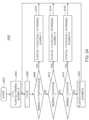
- FIG. 26 is a block diagram of a differential signal comparator 2604 coupled to the digital signal processor 124 in accordance with exemplary embodiments of the present invention.
- the DSP 124 may comprise at least one central processing unit (CPU) coupled to the memory 126 as well as various support circuits (i.e., well known circuits used to promote functionality of the CPU, such as a cache, power supplies, clock circuits, buses, input/output (I/O) circuits, and the like).
- the CPU may comprise one or more conventionally available microprocessors or microcontrollers; in one or more embodiments, the CPU may be a microcontroller comprising internal memory for storing controller firmware that, when executed, provides the functionality described herein.
- the DPS 112 may be implemented using a general purpose computer that, when executing particular software, becomes a specific purpose computer for performing various embodiments of the present invention; in one or more embodiments, the DPS 112 may additionally or alternatively comprise one or more application specific integrated circuits (ASICs) for performing one or more of the functions described herein.
- ASICs application specific integrated circuits
- the system 100 includes memory 126.
- the memory 126 may store an operating system (OS), such as one of a number of available operating systems for microcontrollers and/or microprocessors.
- OS operating system
- the memory 126 also may store non-transient processor-executable instructions and/or data that may be executed by and/or used by the CPU. These processor-executable instructions may comprise firmware, software, and the like, or some combination thereof.
- the memory 126 further includes application software such as the differential signal comparator (DSC) 2604 which compares, analyzes and processes two or more varying input signals to generate one or more processed output signals for more accurate detection of objects which are energized to a hazardous level.
- DSC differential signal comparator
- the DSC 2604 processes signals received from two or more sensor probes (i.e., electrical field sensors). Such processing may include filtering, performing mathematical operations on the signals (e.g., addition, subtraction, and the like), includes time-shifting one or more of the signals, and may include any other applicable processing as described herein.
- the digital signal processor 124 receives digital electric field signal 2600 from a first sensor probe and digital electric field signal 2602 from a second sensor probe spaced apart from the first sensor probe as described in more detail below.
- the DSP 124 may receive more signals, but that only two are shown for clarity.
- the DSP 124 is aware of the configuration of various electric field sensors located on a mobile vehicle, such a rolling cart, a car, a truck, a boat, or the like (e.g., the vehicles shown in Figure 27-34 ).
- the DSP 124 is coupled to memory 126, and communicates the signals 2600 and 2602 to the differential signal comparator 2604.
- the differential signal comparator 2604 performs various functions, as described below, based on the mode of the DSP 124 and the mode of the DSC 2604. For example, in one embodiment, the DSC 2604 may perform processing on the input signals 2600, 2602 to output a noise-reduced signal 2606 via the DSP 124 - where noise has been reduced by operations performed on the two input signals 2600, 2602. In another embodiment, the DSC 2604 may output an amplified signal 2608 via the DSP 124 based on the input signals 2600, 2602.
- the DSP mode and the DSC mode may be pre-programmed, set by a user in real-time, or the like.
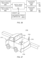
- FIG. 27 illustrates a perspective view of a configuration of two electric field sensors 2702, 2704 mounted to the rear of an automotive vehicle 2701 in accordance with exemplary embodiments of the present invention.
- the first electric field sensor 2702 is mounted to the right rear-end of the vehicle 2701 via mount 2706, while the second electric field sensor 2704 is mounted to the left rear-end of the vehicle 2701 via mount 2708.
- mounts 2706 and 2708 are made of non-electrically interfering material that does not impact the readings of the sensors 2702 and 2704.
- the mounting locations receive similar mechanical input as the vehicle 2701 navigates a roadway.
- vibration and displacement noise would be relatively equally imposed on each sensor 2702 and 2704.
- the sensors 2702 and 2704 are mounted such that they monitor the horizontal plane but are mounted on two different vertical axes, other embodiments may include having the sensors 2702 and 2704 located about a single axis. In other words, the sensor 2702 and 2704 may both be located behind the vehicle 2701 at the center of the lane of travel on a common vertical axis.
- the outputs from the two sensors 2702, 2704 provide information that can be used to determine how far an energized object is from the vehicle 2701.
- an energized manhole cover 2802 is at a distance A from the vehicle 2701
- an energized street light 2804 is at a distance B from the vehicle 2701.
- FIG. 29 depicts exemplary electric field sensor outputs for the configuration shown in FIG. 28
- Plot 2900 shows the left sensor reading 2904 and the right sensor reading 2902 (i.e., the readings from the sensors 2704 and 2702, respectively) corresponding to the energized manhole cover 2802.
- the left and right sensor readings 2904 and 2902 are plotted on a graph of distance vs. amplitude.
- the peaks of the left sensor reading 2904 and the right sensor reading 2902 are at a distance A' from one another, corresponding to the distance A between the vehicle 2701 and the energized manhole cover 2802.
- Plot 2910 shows the left sensor reading 2914 and the right sensor reading 2912 (i.e., the readings from the sensors 2704 and 2702, respectively) corresponding to the energized street light 2804.
- the left and right sensor readings 2914 and 2912 are plotted on a graph of distance vs. amplitude.
- the peaks of the left sensor reading 2914 and the right sensor reading 2912 are at a distance B' from one another, corresponding to the distance B between the vehicle 2701 and the energized street light 2804.
- the plots 2900 and 2910 thus provide an indication (e.g., to a user observing the plots 2900 and 2910 on a user display) of the distance between the energized objects 2802, 2804 and the vehicle 2701.
- the DSC 2604 may compute the distances A and B based on the readings of the sensors 2704, 2702 and may store and/or display the computed information.
- the distance M between the electric field sensors 2702 and 2704 of Figure 28 is zero.
- the known angle between the sensors 2702 and 2704 (which will be referred to here as ⁇ ) and the distance A' that the vehicle 2701 travelled between the detection of the energized manhole cover 2802 by the first sensor (sensor 2704 here) and the detection of the energized manhole cover 2802 by the second sensor (sensor 2702 here) can be used.
- the positioning of the sensors 2704 and 2702 in the embodiment of FIG. 28 allows a determination to be made about whether an energized object is on the right or the left side of the vehicle.
- a sensor signal peak from a left-side mounted sensor i.e., a sensor mounted on the left side of the vehicle with respect to the direction of travel
- a sensor signal peak from a right-side mounted sensor i.e., a sensor mounted on the right side of the vehicle with respect to the direction of travel
- the energized object is on the left side of the direction of travel.
- a sensor signal peak from the right-side mounted sensor is followed by a sensor signal peak from the left-side mounted sensor, the energized object is on the right side of the direction of travel.
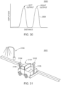
- the DSC 2604 can combine the output of the two sensors 2702 and 2704 to produce a difference output signal such as signal 2606 where the noise is canceled out or reduced significantly as shown in graph 3000 in Figure 30 .
- the signal 2606 shown in Figure 30 has a greater signal to noise ratio than an output signal in a single input system. Additionally, since there are two (or more) sensors 2702, 2704, the two (or more) responses generated by the DSP 124 as the automobile 2701 passes an energized object enables the system 100 to differentiate a true detection from noise, as noise will produce only a single response.
- FIG. 31 illustrates a perspective view 3001 of a configuration of electric field sensors 3104, 3102 mounted respectively to the front and back of an automotive vehicle 3101 in accordance with exemplary embodiments of the present invention.
- the vehicle 3101 is fitted with the first electric field sensor 3102 in the center-rear, mounted via the mount 3106.
- a second electric field sensor 3104 is mounted to the center-front of the vehicle 3101 via mount 3108.
- the mounts 3106 and 3108 are non-electrically interfering so as to avoid any impact on the sensor readings.
- FIG. 31 further depicts a hazardously energized street lamp 3100.
- the sensors 3104 and 3102 each generate a signal corresponding to the sensed electrical field.
- the generated signals are then processed by the DSC 2604 as described herein, and the resulting processed signal or signals are used for generating an indication of the hazardously energized street lamp 3100, such as a visual indication via the GUI 138 and/or an audio indication via the speaker 130.
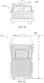
- FIG. 32 illustrates a back view 3200 of vehicle 3101 having the electric field sensors 3102 and 3104 mounted to the back and front, respectively, as shown in FIG. 31 .
- the electric field sensor 3102 is mounted to the in the center-rear of the vehicle 3101 via the mount 3106.
- FIG. 33 illustrates a top-down view 3300 of the same configuration of the electric field sensors 3102, 3104 mounted to the front and back of the automotive vehicle 3101 shown in Fig. 31-32 in accordance with exemplary embodiments of the present invention.
- the sensors 3104, 3102 are substantially parallel to one another, and, as a result, as the vehicle 3101 moves forward the front sensor 3104 first detects the electric field of an energized object, followed by the rear sensor 3102 detecting the electric field of the energized object.
- the sensors 3104, 3102 are spaced a distance D apart from one another on the vehicle 3101, and thus the rear sensor 3102 will produce an output, when the vehicle moves a distance D forward, substantially the same as that produced by the front sensor 3104..
- the expected output of sensors 3102 and 3104 when positioned substantially parallel to one another as shown in FIGS. 31-33 is thus two responses as the vehicle 3101 approaches and passes a hazardously energized object, for instance the energized street light 3100 shown in Figure 31 , with the two responses separated in time by the time it takes for the vehicle 3101 to advance the distance D between the two sensors 3102, 3104.
- the DSC 2604 processes the received signals by time-shifting one or both signals by an amount commensurate with the difference in time between the sensors sensing the same point in the electric field; for example, for an embodiment such as the embodiment depicted in FIG.
- one of the received signals may be time-shifted by the amount of time it takes for the vehicle 3101 to travel a distance equal to the distance between the sensors 3102, 3104.
- the DSC 2604 may time-shift one or both of the received signals based on data (e.g., the distance between the sensors 3102, 3104) that is pre-programmed, entered by a user, downloaded from another component or system, computed based on one or more received signals, or by a similar technique. Subsequent to time-shifting, the two sensor signals is added together to obtain a signal output signal, for example as shown in FIG. 35 described below. Adding the two responses subsequent to time-shifting commensurate with the distance between the sensors provides a greater signal output with significantly less noise.
- FIG. 34 illustrates a graphical plot of the output of the sensors 3102, 3104 illustrated in FIGS. 31-33 in accordance with exemplary embodiments of the present invention.
- a first signal 3402, received from the front-mounted sensor 3104 is shown on a first graph 3404 of distance traveled by the vehicle 3101 vs. amplitude;
- a second signal 3406, received from the rear-mounted sensor 3102 is shown on a second graph 3408 of distance traveled by the vehicle 3101 vs. signal amplitude.
- Each signal 3402, 3406 contains noise received while passing the hazardous object 3100, and the signals 3402, 3406 are separated by the time it takes the automobile 3101 to traverse the distance between the two sensors 3102 and 3104.
- the desired signal from the hazardous object 3100 will appear at both sensors 3102, 3104 separated in time while random noise will appear simultaneously.
- the signals 3402 and 3406 - can be combined and evaluated accordingly.
- Figure 35 illustrates the combination of the two signals 3402, 3406, one of which is time-shifted, along with the accompanied noise reduction.
- a combined signal 3502 generated from the two signals 3402, 3406 - one of the two being time-shifted - is shown on graph 3504 of distance traveled by the vehicle 3101 vs. signal amplitude. Since the noise impulse appears in both the front and rear sensors 3104 and 3102 at the same time, and the desired signal from the hazardous object 3100 appears separated in time, the output of the time shift function will show the combined signal 3502 having a maximum amplitude at twice the maximum amplitude of the original signals 3402, 3406, and the noise impulse will appear twice at the original amplitude of the noise impulse.
- An alternate methodology is to add a gate function that compares the signal from the rear sensor 3102 to the time-shifted signal from the front sensor 3104. If an energized object is encountered, there will be similar signals available from each of the sensors 3102 and 3104. When the signals are passed to a gate function, for example a logical AND function, the gate function will indicate the affirmative case. A noise impulse will create two signals separated in time due to the time shift function. When the noise impulses are also passed to the gate function, e.g., the logical AND, the gate will indicate the negative case.
- FIG. 36 is a flow diagram of a method 3600 for detecting and identifying hazardous objects in electric fields in accordance with one or more embodiments of the present invention.
- the method 3600 is, at least in part, one implementation of the differential signal comparator 2604.
- the method 3600 proceeds to step 3606, where the received signals are processed as previously described to generate at least one processed signal based on a distance between at least two sensor probes of the two or more sensor probes.
- two received signals from two sensor probes may be processed as previously described to one or more processed signals as shown in FIGS. 29-30 , 34-35 , and 37
- the method 3600 proceeds to step 3608.
- the processed signal (or signals) from step 3606 is used to generate an indication of a hazardously energized object, such as the hazardously energized street lamp 3100.
- the processed signal may be displayed for providing a visual indication to a user of a hazardously energized object.
- a signal such as the signal shown in FIG. 30 may be displayed to a user for the user to identify the hazardously energized object based on visually observing the dual spikes in the signal, or a signal such as the signal shown in FIG. 35 may be displayed to identify the hazardously energized object based on visually observing the large single spike in the signal.
- the processed signal may be used to generate an audio indication such as a tone corresponding in pitch and/or volume to the signal amplitude.
- the processor e.g., the DSC 2604 may sense a rise-peak-fall in the processed signal followed by a similar rise-peak-fall at an interval expected based on the sensor separation, and generate a visual and/or audio indication (e.g., a light, a tone, or the like).
- the method 3600 proceeds to step 3608 where a determination is made whether to continue. If the result of the determination is yes, the method 3600 returns to step 3604.
- the foregoing sensor, system, apparatus and method are described in terms of the 60 Hz electrical power system frequency common in the United States and other countries, the apparatus, arrangements and methods described herein are likewise applicable to the 50 Hz power systems of Europe and elsewhere, to the 400 Hz power systems for aircraft and other apparatus, to the 25 Hz power systems for transportation and other applications, and to power systems at any other frequency. Further, while the arrangement is often described in terms such as “stray voltage” and “voltage anomaly” and “stray voltage” field, it is noted that the electric field produced by the conditions so referred to is sensed and/or detected by the described arrangement.
- Figure 37 illustrates user displays 3700 and 3701 showing outputs of the electric field sensors 3104, 3102 of FIG. 33 in accordance with exemplary embodiments of the present invention.
- the electric field sensors 3104 and 3102 are positioned at the center-front and center-rear, respectively, of the vehicle 3101.
- the user display 3700 shows sensor output 3704 (i.e., received from the sensor 3104) positioned above a time-shifted sensor output 3702 (received from the sensor 3102 and time-shifted by the amount of time it takes for the vehicle 3101 to travel the distance D between the sensors 3104, 3102).
- the sensor output 3704 and the time-shifted sensor output 3702 do not display any peaks of similar amplitude at substantially the same time, thereby indicating no hazardously energized objects were detected (i.e., a negative indication for a hazardously energized object). A user can thus visually determine that no hazardously energized objects have been detected.
- the user display 3701 shows sensor output 3714 (i.e., received from the sensor 3104) positioned above a time-shifted sensor output 3712 (received from the sensor 3102 and time-shifted by the amount of time it takes for the vehicle 3101 to travel the distance D between the sensors 3104, 3102).
- the sensor output 3714 and the time-shifted sensor output 3712 display peaks 3724 and 3712, respectively, of substantially the same size and shape and occurring at substantially the same time, thereby indicating a hazardously energized object has been detected (i.e., a positive indication for a hazardously energized object).
- a user can thus visually determine that a hazardously energized object has been detected.
Landscapes
- Physics & Mathematics (AREA)
- General Physics & Mathematics (AREA)
- Business, Economics & Management (AREA)
- Emergency Management (AREA)
- Traffic Control Systems (AREA)
- Measurement Of Length, Angles, Or The Like Using Electric Or Magnetic Means (AREA)
- Geophysics And Detection Of Objects (AREA)
- Force Measurement Appropriate To Specific Purposes (AREA)
Claims (12)
- Einrichtung (100) zum Erfassen und Identifizieren von gefährlichen Objekten in elektrischen Feldern, umfassend:zwei oder mehr Sensorsonden (2702, 2704, 3102, 3104), die dazu konfiguriert sind, auf einem mobilen Fahrzeug montiert und voneinander beabstandet zu werden, wobei jede Sensorsonde der zwei oder mehr Sensorsonden dazu konfiguriert ist, ein Signal zu erzeugen, das mit einem elektrischen Feld korrespondiert;einen Prozessor (124), der mit den zwei oder mehr Sensorsonden gekoppelt ist, die dazu konfiguriert sind, die Signale von den zwei oder mehr Sensorsonden zum Erzeugen mindestens eines verarbeiteten Signals basierend auf einem Abstand zwischen mindestens zwei Sensorsonden der zwei oder mehr Sensorsonden zu verarbeiten; undeinen Anzeiger, der mit dem Prozessor zum Bereitstellen, basierend auf dem mindestens einen verarbeiteten Signal, einer Anzeige eines gefährlich spannungsführenden Objekts in dem elektrischen Feld gekoppelt ist, wobei das Verarbeiten der Signale von den zwei oder mehr Sensorsonden ein Hinzufügen eines ersten Signals von einer ersten Sensorsonde der zwei oder mehr Sensorsonden und eines zweiten Signals von einer zweiten Sensorsonde der zwei oder mehr Sensorsonden umfasst, dadurch gekennzeichnet, dass mindestens eines von dem ersten Signal oder dem zweiten Signal, vor dem Hinzufügen des ersten Signals und des zweiten Signals, um einen Betrag, der einem Abstand zwischen der ersten und der zweiten Sensorsonde proportional ist, zeitlich verschoben ist.
- Einrichtung nach Anspruch 1, ferner umfassend:
das mobile Fahrzeug (2701, 3101), wobei die zwei oder mehr Sensorsonden an Stellen auf dem mobilen Fahrzeug montiert sind, die eine ähnliche mechanische Eingabe aufgrund von einer Bewegung aufnehmen. - Einrichtung nach Anspruch 1, ferner umfassend:
das mobile Fahrzeug (2701, 3101), wobei die zwei oder mehr Sensorsonden eine erste Sensorsonde (2702) und eine zweite Sensorsonde (2704) umfassen, wobei (i) die erste und die zweite Sensorsonde an der Rückseite des mobilen Fahrzeugs montiert sind oder (ii) die erste Sensorsonde (3104) an der Vorderseite des mobilen Fahrzeugs (3101) montiert ist und die zweite Sensorsonde (3102) an der Rückseite des mobilen Fahrzeugs montiert ist. - Einrichtung nach Anspruch 2, wobei die zwei oder mehr Sensorsonden eine erste Sensorsonde (2702) und eine zweite Sensorsonde (2704) umfassen, wobei (i) die erste und die zweite Sensorsonde an der Rückseite des mobilen Fahrzeugs (2701) montiert sind oder (ii) die erste Sensorsonde (3104) an der Vorderseite des mobilen Fahrzeugs (3101) montiert ist und die zweite Sensorsonde (3102) an der Rückseite des mobilen Fahrzeugs montiert ist.
- Einrichtung nach einem der Ansprüche 3 oder 4, wobei die erste und die zweite Sensorsonde auf der gleichen horizontalen Ebene montiert sind.
- Einrichtung nach einem der Ansprüche 3 bis 5, wobei die erste und die zweite Sensorsonde in einem veränderbaren Winkel zueinander montiert sind und durch einen veränderbaren Abstand getrennt sind.
- Einrichtung nach einem der Ansprüche 2 bis 6, wobei jede der zwei oder mehr Sensorsonden durch ein nicht elektrisch störendes Material auf dem mobilen Fahrzeug montiert ist.
- Verfahren zum Erfassen und Identifizieren von gefährlichen Objekten in elektrischen Feldern, umfassend:Erhalten eines Signals, von jeder Sensorsonde von zwei oder mehr Sensorsonden (2702, 2704, 3102, 3104), die auf einem mobilen Fahrzeug (2701, 3101) montiert und voneinander beabstandet sind, das mit einem elektrischen Feld korrespondiert;Verarbeiten der Signale von den zwei oder mehr Sensorsonden zum Erzeugen mindestens eines verarbeiteten Signals basierend auf einem Abstand zwischen mindestens zwei Sensorsonden der zwei oder mehr Sensorsonden; undErzeugen, basierend auf dem mindestens einen verarbeiteten Signal, einer Anzeige eines gefährlich spannungsführenden Objekts in dem elektrischen Feld, wobei das Verarbeiten der Signale von den zwei oder mehr Sensorsonden das Hinzufügen eines ersten Signals von einer ersten Sensorsonde der zwei oder mehr Sensorsonden und eines zweiten Signals von einer zweiten Sensorsonde der zwei oder mehr Sensorsonden umfasst, dadurch gekennzeichnet, dass mindestens eines von dem ersten Signal oder dem zweiten Signal, vor dem Hinzufügen des ersten Signals und des zweiten Signals, um einen Betrag, der einem Abstand zwischen der ersten und der zweiten Sensorsonde proportional ist, zeitlich verschoben ist.
- Verfahren nach Anspruch 8, wobei die zwei oder mehr Sensorsonden eine erste Sensorsonde (2702) und eine zweite Sensorsonde (2704) umfassen, wobei (i) die erste und die zweite Sensorsonde an der Rückseite des mobilen Fahrzeugs (2701) montiert sind oder (ii) die erste Sensorsonde (3104) an der Vorderseite des mobilen Fahrzeugs (3101) montiert ist und die zweite Sensorsonde (3102) an der Rückseite des mobilen Fahrzeugs montiert ist.
- Verfahren nach Anspruch 9, wobei die erste und die zweite Sensorsonde auf der gleichen horizontalen Ebene montiert sind.
- Verfahren nach einem der Ansprüche 9 oder 10, wobei die erste und die zweite Sensorsonde in einem veränderbaren Winkel zueinander montiert sind und durch einen veränderbaren Abstand getrennt sind.
- Verfahren nach Anspruch 11, wobei jede der zwei oder mehr Sensorsonden durch ein nicht elektrisch störendes Material auf dem mobilen Fahrzeug montiert ist.
Applications Claiming Priority (2)
| Application Number | Priority Date | Filing Date | Title |
|---|---|---|---|
| US201762455200P | 2017-02-06 | 2017-02-06 | |
| PCT/US2018/016852 WO2018203945A2 (en) | 2017-02-06 | 2018-02-05 | Apparatus and method for detection of hazardously energized objects |
Publications (3)
| Publication Number | Publication Date |
|---|---|
| EP3577472A2 EP3577472A2 (de) | 2019-12-11 |
| EP3577472A4 EP3577472A4 (de) | 2021-01-06 |
| EP3577472B1 true EP3577472B1 (de) | 2023-09-13 |
Family
ID=63037856
Family Applications (1)
| Application Number | Title | Priority Date | Filing Date |
|---|---|---|---|
| EP18794631.4A Active EP3577472B1 (de) | 2017-02-06 | 2018-02-05 | Vorrichtung und verfahren zum nachweis von gefährlich spannungsführenden objekten |
Country Status (9)
| Country | Link |
|---|---|
| US (1) | US10916116B2 (de) |
| EP (1) | EP3577472B1 (de) |
| CA (1) | CA3049918C (de) |
| DK (1) | DK3577472T3 (de) |
| ES (1) | ES2962304T3 (de) |
| FI (1) | FI3577472T3 (de) |
| PL (1) | PL3577472T3 (de) |
| PT (1) | PT3577472T (de) |
| WO (1) | WO2018203945A2 (de) |
Families Citing this family (3)
| Publication number | Priority date | Publication date | Assignee | Title |
|---|---|---|---|---|
| DE102020134199A1 (de) * | 2020-12-18 | 2022-06-23 | PEEK GmbH | Verfahren und vorrichtung zur detektion von elektrischen spannungen und/oder elektrischen strömen |
| CN116338289B (zh) * | 2023-04-18 | 2025-09-16 | 淄博文广电气有限公司 | 一种物体表面带电非接触式检测装置 |
| US20250276691A1 (en) * | 2024-03-04 | 2025-09-04 | Ford Global Technologies, Llc | Vehicle incremental movement system |
Family Cites Families (15)
| Publication number | Priority date | Publication date | Assignee | Title |
|---|---|---|---|---|
| US3662260A (en) * | 1971-02-12 | 1972-05-09 | Us Navy | Electric field measuring instrument with probe for sensing three orthogonal components |
| EP1180904A1 (de) * | 2000-07-18 | 2002-02-20 | Pioneer Corporation | Mobilkommunikationssystem |
| US20030167139A1 (en) * | 2001-04-26 | 2003-09-04 | Mcnc | Electromagnetic emission source identification apparatus and associated method, computer device,and computer software program product |
| EP1461789A4 (de) * | 2001-12-10 | 2010-10-06 | Bae Systems Information | Sensor für elektrische felder |
| US7078911B2 (en) * | 2003-02-06 | 2006-07-18 | Cehelnik Thomas G | Patent application for a computer motional command interface |
| US8598864B2 (en) | 2004-12-23 | 2013-12-03 | Power Survey Llc | Apparatus and method for monitoring and controlling detection of stray voltage anomalies |
| US7253642B2 (en) * | 2004-12-23 | 2007-08-07 | Power Survey Company | Method for sensing an electric field |
| US9110120B2 (en) * | 2004-12-23 | 2015-08-18 | Power Survey Llc | Apparatus and method for monitoring and controlling detection of stray voltage anomalies |
| US7248054B2 (en) | 2004-12-23 | 2007-07-24 | Power Survey Company | Apparatus and method for detecting an electric field |
| US7486081B2 (en) | 2005-09-13 | 2009-02-03 | Power Survey Llc | Apparatus and method for monitoring and controlling detection of stray voltage anomalies |
| US7449892B2 (en) * | 2006-06-02 | 2008-11-11 | Cal-Tek 2000, Inc. | Stray voltage detecting |
| US8577631B2 (en) | 2010-01-26 | 2013-11-05 | Power Survey Llc | Method and apparatus for discrimination of sources in stray voltage detection |
| FI3546960T3 (fi) * | 2014-01-07 | 2023-07-19 | Osmose Utilities Services Inc | Laitteisto ja menetelmä harhajännitepoikkeamien havaitsemisen valvomiseksi ja ohjaamiseksi käyttämällä fotonianturia |
| JP6539133B2 (ja) * | 2015-07-09 | 2019-07-03 | クラリオン株式会社 | 車載端末およびプログラム |
| AU2016297681B2 (en) | 2015-07-20 | 2021-05-06 | The Peak Group Pty Limited | Apparatus and method for identifying defects in conduits |
-
2018
- 2018-02-05 EP EP18794631.4A patent/EP3577472B1/de active Active
- 2018-02-05 PL PL18794631.4T patent/PL3577472T3/pl unknown
- 2018-02-05 WO PCT/US2018/016852 patent/WO2018203945A2/en not_active Ceased
- 2018-02-05 ES ES18794631T patent/ES2962304T3/es active Active
- 2018-02-05 DK DK18794631.4T patent/DK3577472T3/da active
- 2018-02-05 CA CA3049918A patent/CA3049918C/en active Active
- 2018-02-05 PT PT187946314T patent/PT3577472T/pt unknown
- 2018-02-05 US US15/888,561 patent/US10916116B2/en active Active
- 2018-02-05 FI FIEP18794631.4T patent/FI3577472T3/fi active
Also Published As
| Publication number | Publication date |
|---|---|
| US10916116B2 (en) | 2021-02-09 |
| EP3577472A2 (de) | 2019-12-11 |
| US20180225946A1 (en) | 2018-08-09 |
| PL3577472T3 (pl) | 2024-03-11 |
| WO2018203945A2 (en) | 2018-11-08 |
| CA3049918C (en) | 2023-01-24 |
| CA3049918A1 (en) | 2018-11-08 |
| DK3577472T3 (da) | 2023-11-20 |
| FI3577472T3 (fi) | 2023-11-13 |
| WO2018203945A3 (en) | 2018-12-27 |
| PT3577472T (pt) | 2023-11-03 |
| EP3577472A4 (de) | 2021-01-06 |
| ES2962304T3 (es) | 2024-03-18 |
Similar Documents
| Publication | Publication Date | Title |
|---|---|---|
| CA2750104C (en) | Apparatus and method for monitoring and controlling detection of stray voltage anomalies | |
| US9520044B2 (en) | Apparatus and method for monitoring and controlling detection of stray voltage anomalies | |
| CA2592017C (en) | Sensor for sensing an electric field | |
| US7253642B2 (en) | Method for sensing an electric field | |
| US20070179737A1 (en) | Apparatus and method for monitoring and controlling detection of stray voltage anomalies | |
| EP3092504B1 (de) | Vorrichtung zur überwachung und steuerung der erkennung einer potenzialverschleppung anhand eines optischen sensors | |
| EP3577472B1 (de) | Vorrichtung und verfahren zum nachweis von gefährlich spannungsführenden objekten | |
| EP2016371B1 (de) | Vorrichtung und verfahren zur überwachung und steuerung der erfassung von streuspannungsunregelmässigkeiten |
Legal Events
| Date | Code | Title | Description |
|---|---|---|---|
| STAA | Information on the status of an ep patent application or granted ep patent |
Free format text: STATUS: THE INTERNATIONAL PUBLICATION HAS BEEN MADE |
|
| PUAI | Public reference made under article 153(3) epc to a published international application that has entered the european phase |
Free format text: ORIGINAL CODE: 0009012 |
|
| STAA | Information on the status of an ep patent application or granted ep patent |
Free format text: STATUS: REQUEST FOR EXAMINATION WAS MADE |
|
| 17P | Request for examination filed |
Effective date: 20190906 |
|
| AK | Designated contracting states |
Kind code of ref document: A2 Designated state(s): AL AT BE BG CH CY CZ DE DK EE ES FI FR GB GR HR HU IE IS IT LI LT LU LV MC MK MT NL NO PL PT RO RS SE SI SK SM TR |
|
| AX | Request for extension of the european patent |
Extension state: BA ME |
|
| DAV | Request for validation of the european patent (deleted) | ||
| DAX | Request for extension of the european patent (deleted) | ||
| RAP1 | Party data changed (applicant data changed or rights of an application transferred) |
Owner name: OSMOSE UTILITIES SERVICES, INC. |
|
| REG | Reference to a national code |
Ref country code: DE Ref legal event code: R079 Free format text: PREVIOUS MAIN CLASS: G01R0031020000 Ipc: G01R0029120000 Ref country code: DE Ref legal event code: R079 Ref document number: 602018057562 Country of ref document: DE Free format text: PREVIOUS MAIN CLASS: G01R0031020000 Ipc: G01R0029120000 |
|
| A4 | Supplementary search report drawn up and despatched |
Effective date: 20201203 |
|
| RIC1 | Information provided on ipc code assigned before grant |
Ipc: G01R 29/12 20060101AFI20201127BHEP |
|
| GRAP | Despatch of communication of intention to grant a patent |
Free format text: ORIGINAL CODE: EPIDOSNIGR1 |
|
| STAA | Information on the status of an ep patent application or granted ep patent |
Free format text: STATUS: GRANT OF PATENT IS INTENDED |
|
| INTG | Intention to grant announced |
Effective date: 20230210 |
|
| GRAJ | Information related to disapproval of communication of intention to grant by the applicant or resumption of examination proceedings by the epo deleted |
Free format text: ORIGINAL CODE: EPIDOSDIGR1 |
|
| STAA | Information on the status of an ep patent application or granted ep patent |
Free format text: STATUS: REQUEST FOR EXAMINATION WAS MADE |
|
| GRAP | Despatch of communication of intention to grant a patent |
Free format text: ORIGINAL CODE: EPIDOSNIGR1 |
|
| STAA | Information on the status of an ep patent application or granted ep patent |
Free format text: STATUS: GRANT OF PATENT IS INTENDED |
|
| INTC | Intention to grant announced (deleted) | ||
| INTG | Intention to grant announced |
Effective date: 20230417 |
|
| P01 | Opt-out of the competence of the unified patent court (upc) registered |
Effective date: 20230524 |
|
| GRAS | Grant fee paid |
Free format text: ORIGINAL CODE: EPIDOSNIGR3 |
|
| GRAA | (expected) grant |
Free format text: ORIGINAL CODE: 0009210 |
|
| STAA | Information on the status of an ep patent application or granted ep patent |
Free format text: STATUS: THE PATENT HAS BEEN GRANTED |
|
| AK | Designated contracting states |
Kind code of ref document: B1 Designated state(s): AL AT BE BG CH CY CZ DE DK EE ES FI FR GB GR HR HU IE IS IT LI LT LU LV MC MK MT NL NO PL PT RO RS SE SI SK SM TR |
|
| REG | Reference to a national code |
Ref country code: CH Ref legal event code: EP |
|
| REG | Reference to a national code |
Ref country code: DE Ref legal event code: R096 Ref document number: 602018057562 Country of ref document: DE |
|
| REG | Reference to a national code |
Ref country code: IE Ref legal event code: FG4D |
|
| REG | Reference to a national code |
Ref country code: PT Ref legal event code: SC4A Ref document number: 3577472 Country of ref document: PT Date of ref document: 20231103 Kind code of ref document: T Free format text: AVAILABILITY OF NATIONAL TRANSLATION Effective date: 20231027 |
|
| REG | Reference to a national code |
Ref country code: FI Ref legal event code: FGE |
|
| REG | Reference to a national code |
Ref country code: DK Ref legal event code: T3 Effective date: 20231115 |
|
| REG | Reference to a national code |
Ref country code: SE Ref legal event code: TRGR |
|
| REG | Reference to a national code |
Ref country code: NL Ref legal event code: FP |
|
| REG | Reference to a national code |
Ref country code: NO Ref legal event code: T2 Effective date: 20230913 |
|
| REG | Reference to a national code |
Ref country code: LT Ref legal event code: MG9D |
|
| PG25 | Lapsed in a contracting state [announced via postgrant information from national office to epo] |
Ref country code: GR Free format text: LAPSE BECAUSE OF FAILURE TO SUBMIT A TRANSLATION OF THE DESCRIPTION OR TO PAY THE FEE WITHIN THE PRESCRIBED TIME-LIMIT Effective date: 20231214 |
|
| PG25 | Lapsed in a contracting state [announced via postgrant information from national office to epo] |
Ref country code: RS Free format text: LAPSE BECAUSE OF FAILURE TO SUBMIT A TRANSLATION OF THE DESCRIPTION OR TO PAY THE FEE WITHIN THE PRESCRIBED TIME-LIMIT Effective date: 20230913 Ref country code: LV Free format text: LAPSE BECAUSE OF FAILURE TO SUBMIT A TRANSLATION OF THE DESCRIPTION OR TO PAY THE FEE WITHIN THE PRESCRIBED TIME-LIMIT Effective date: 20230913 Ref country code: LT Free format text: LAPSE BECAUSE OF FAILURE TO SUBMIT A TRANSLATION OF THE DESCRIPTION OR TO PAY THE FEE WITHIN THE PRESCRIBED TIME-LIMIT Effective date: 20230913 Ref country code: HR Free format text: LAPSE BECAUSE OF FAILURE TO SUBMIT A TRANSLATION OF THE DESCRIPTION OR TO PAY THE FEE WITHIN THE PRESCRIBED TIME-LIMIT Effective date: 20230913 Ref country code: GR Free format text: LAPSE BECAUSE OF FAILURE TO SUBMIT A TRANSLATION OF THE DESCRIPTION OR TO PAY THE FEE WITHIN THE PRESCRIBED TIME-LIMIT Effective date: 20231214 |
|
| REG | Reference to a national code |
Ref country code: AT Ref legal event code: UEP Ref document number: 1611802 Country of ref document: AT Kind code of ref document: T Effective date: 20230913 |
|
| REG | Reference to a national code |
Ref country code: ES Ref legal event code: FG2A Ref document number: 2962304 Country of ref document: ES Kind code of ref document: T3 Effective date: 20240318 |
|
| PG25 | Lapsed in a contracting state [announced via postgrant information from national office to epo] |
Ref country code: IS Free format text: LAPSE BECAUSE OF FAILURE TO SUBMIT A TRANSLATION OF THE DESCRIPTION OR TO PAY THE FEE WITHIN THE PRESCRIBED TIME-LIMIT Effective date: 20240113 |
|
| PG25 | Lapsed in a contracting state [announced via postgrant information from national office to epo] |
Ref country code: SM Free format text: LAPSE BECAUSE OF FAILURE TO SUBMIT A TRANSLATION OF THE DESCRIPTION OR TO PAY THE FEE WITHIN THE PRESCRIBED TIME-LIMIT Effective date: 20230913 Ref country code: RO Free format text: LAPSE BECAUSE OF FAILURE TO SUBMIT A TRANSLATION OF THE DESCRIPTION OR TO PAY THE FEE WITHIN THE PRESCRIBED TIME-LIMIT Effective date: 20230913 Ref country code: IS Free format text: LAPSE BECAUSE OF FAILURE TO SUBMIT A TRANSLATION OF THE DESCRIPTION OR TO PAY THE FEE WITHIN THE PRESCRIBED TIME-LIMIT Effective date: 20240113 Ref country code: EE Free format text: LAPSE BECAUSE OF FAILURE TO SUBMIT A TRANSLATION OF THE DESCRIPTION OR TO PAY THE FEE WITHIN THE PRESCRIBED TIME-LIMIT Effective date: 20230913 Ref country code: CZ Free format text: LAPSE BECAUSE OF FAILURE TO SUBMIT A TRANSLATION OF THE DESCRIPTION OR TO PAY THE FEE WITHIN THE PRESCRIBED TIME-LIMIT Effective date: 20230913 Ref country code: SK Free format text: LAPSE BECAUSE OF FAILURE TO SUBMIT A TRANSLATION OF THE DESCRIPTION OR TO PAY THE FEE WITHIN THE PRESCRIBED TIME-LIMIT Effective date: 20230913 |
|
| REG | Reference to a national code |
Ref country code: DE Ref legal event code: R097 Ref document number: 602018057562 Country of ref document: DE |
|
| PLBE | No opposition filed within time limit |
Free format text: ORIGINAL CODE: 0009261 |
|
| STAA | Information on the status of an ep patent application or granted ep patent |
Free format text: STATUS: NO OPPOSITION FILED WITHIN TIME LIMIT |
|
| 26N | No opposition filed |
Effective date: 20240614 |
|
| PG25 | Lapsed in a contracting state [announced via postgrant information from national office to epo] |
Ref country code: MC Free format text: LAPSE BECAUSE OF FAILURE TO SUBMIT A TRANSLATION OF THE DESCRIPTION OR TO PAY THE FEE WITHIN THE PRESCRIBED TIME-LIMIT Effective date: 20230913 |
|
| PG25 | Lapsed in a contracting state [announced via postgrant information from national office to epo] |
Ref country code: LU Free format text: LAPSE BECAUSE OF NON-PAYMENT OF DUE FEES Effective date: 20240205 |
|
| PG25 | Lapsed in a contracting state [announced via postgrant information from national office to epo] |
Ref country code: SI Free format text: LAPSE BECAUSE OF FAILURE TO SUBMIT A TRANSLATION OF THE DESCRIPTION OR TO PAY THE FEE WITHIN THE PRESCRIBED TIME-LIMIT Effective date: 20230913 |
|
| PG25 | Lapsed in a contracting state [announced via postgrant information from national office to epo] |
Ref country code: SI Free format text: LAPSE BECAUSE OF FAILURE TO SUBMIT A TRANSLATION OF THE DESCRIPTION OR TO PAY THE FEE WITHIN THE PRESCRIBED TIME-LIMIT Effective date: 20230913 Ref country code: LU Free format text: LAPSE BECAUSE OF NON-PAYMENT OF DUE FEES Effective date: 20240205 |
|
| PG25 | Lapsed in a contracting state [announced via postgrant information from national office to epo] |
Ref country code: BG Free format text: LAPSE BECAUSE OF FAILURE TO SUBMIT A TRANSLATION OF THE DESCRIPTION OR TO PAY THE FEE WITHIN THE PRESCRIBED TIME-LIMIT Effective date: 20230913 |
|
| PG25 | Lapsed in a contracting state [announced via postgrant information from national office to epo] |
Ref country code: BG Free format text: LAPSE BECAUSE OF FAILURE TO SUBMIT A TRANSLATION OF THE DESCRIPTION OR TO PAY THE FEE WITHIN THE PRESCRIBED TIME-LIMIT Effective date: 20230913 |
|
| PGFP | Annual fee paid to national office [announced via postgrant information from national office to epo] |
Ref country code: NL Payment date: 20250127 Year of fee payment: 8 |
|
| PGFP | Annual fee paid to national office [announced via postgrant information from national office to epo] |
Ref country code: PT Payment date: 20250120 Year of fee payment: 8 Ref country code: DE Payment date: 20250121 Year of fee payment: 8 |
|
| PGFP | Annual fee paid to national office [announced via postgrant information from national office to epo] |
Ref country code: DK Payment date: 20250214 Year of fee payment: 8 Ref country code: FI Payment date: 20250218 Year of fee payment: 8 |
|
| PGFP | Annual fee paid to national office [announced via postgrant information from national office to epo] |
Ref country code: ES Payment date: 20250307 Year of fee payment: 8 |
|
| PGFP | Annual fee paid to national office [announced via postgrant information from national office to epo] |
Ref country code: IE Payment date: 20250123 Year of fee payment: 8 Ref country code: SE Payment date: 20250128 Year of fee payment: 8 |
|
| PGFP | Annual fee paid to national office [announced via postgrant information from national office to epo] |
Ref country code: NO Payment date: 20250212 Year of fee payment: 8 |
|
| PGFP | Annual fee paid to national office [announced via postgrant information from national office to epo] |
Ref country code: CH Payment date: 20250301 Year of fee payment: 8 Ref country code: AT Payment date: 20250127 Year of fee payment: 8 Ref country code: BE Payment date: 20250123 Year of fee payment: 8 |
|
| PGFP | Annual fee paid to national office [announced via postgrant information from national office to epo] |
Ref country code: FR Payment date: 20250121 Year of fee payment: 8 Ref country code: PL Payment date: 20250129 Year of fee payment: 8 |
|
| PGFP | Annual fee paid to national office [announced via postgrant information from national office to epo] |
Ref country code: GB Payment date: 20250123 Year of fee payment: 8 Ref country code: IT Payment date: 20250129 Year of fee payment: 8 |
|
| PGFP | Annual fee paid to national office [announced via postgrant information from national office to epo] |
Ref country code: TR Payment date: 20250203 Year of fee payment: 8 |
|
| PG25 | Lapsed in a contracting state [announced via postgrant information from national office to epo] |
Ref country code: CY Free format text: LAPSE BECAUSE OF FAILURE TO SUBMIT A TRANSLATION OF THE DESCRIPTION OR TO PAY THE FEE WITHIN THE PRESCRIBED TIME-LIMIT; INVALID AB INITIO Effective date: 20180205 |
|
| PG25 | Lapsed in a contracting state [announced via postgrant information from national office to epo] |
Ref country code: HU Free format text: LAPSE BECAUSE OF FAILURE TO SUBMIT A TRANSLATION OF THE DESCRIPTION OR TO PAY THE FEE WITHIN THE PRESCRIBED TIME-LIMIT; INVALID AB INITIO Effective date: 20180205 |