EP3577340B1 - Method and arrangement related to heating of wings in wind power plants - Google Patents
Method and arrangement related to heating of wings in wind power plants Download PDFInfo
- Publication number
- EP3577340B1 EP3577340B1 EP18747135.4A EP18747135A EP3577340B1 EP 3577340 B1 EP3577340 B1 EP 3577340B1 EP 18747135 A EP18747135 A EP 18747135A EP 3577340 B1 EP3577340 B1 EP 3577340B1
- Authority
- EP
- European Patent Office
- Prior art keywords
- heating
- mat
- wing
- heating mat
- mats
- Prior art date
- Legal status (The legal status is an assumption and is not a legal conclusion. Google has not performed a legal analysis and makes no representation as to the accuracy of the status listed.)
- Active
Links
- 238000010438 heat treatment Methods 0.000 title claims description 72
- 238000000034 method Methods 0.000 title claims description 12
- 238000009945 crocheting Methods 0.000 claims description 4
- 238000009940 knitting Methods 0.000 claims description 4
- 238000012544 monitoring process Methods 0.000 claims description 3
- 230000001012 protector Effects 0.000 claims description 3
- RYGMFSIKBFXOCR-UHFFFAOYSA-N Copper Chemical compound [Cu] RYGMFSIKBFXOCR-UHFFFAOYSA-N 0.000 claims description 2
- 239000002184 metal Substances 0.000 claims description 2
- 229910052751 metal Inorganic materials 0.000 claims description 2
- 239000004593 Epoxy Substances 0.000 description 8
- 230000015572 biosynthetic process Effects 0.000 description 7
- 238000009434 installation Methods 0.000 description 7
- 230000008901 benefit Effects 0.000 description 6
- 239000004020 conductor Substances 0.000 description 6
- 230000008569 process Effects 0.000 description 5
- 229920001187 thermosetting polymer Polymers 0.000 description 5
- 239000004033 plastic Substances 0.000 description 4
- 229920003023 plastic Polymers 0.000 description 4
- 238000010792 warming Methods 0.000 description 4
- 238000013461 design Methods 0.000 description 3
- 239000003365 glass fiber Substances 0.000 description 3
- 238000005259 measurement Methods 0.000 description 3
- 238000009529 body temperature measurement Methods 0.000 description 2
- 238000004891 communication Methods 0.000 description 2
- 238000001514 detection method Methods 0.000 description 2
- 239000011888 foil Substances 0.000 description 2
- 239000000463 material Substances 0.000 description 2
- 239000002985 plastic film Substances 0.000 description 2
- 230000001681 protective effect Effects 0.000 description 2
- 230000002787 reinforcement Effects 0.000 description 2
- 229910000639 Spring steel Inorganic materials 0.000 description 1
- 230000006835 compression Effects 0.000 description 1
- 238000007906 compression Methods 0.000 description 1
- 238000001816 cooling Methods 0.000 description 1
- 230000000694 effects Effects 0.000 description 1
- 239000000835 fiber Substances 0.000 description 1
- 238000004519 manufacturing process Methods 0.000 description 1
- 238000012986 modification Methods 0.000 description 1
- 230000004048 modification Effects 0.000 description 1
- 229920000728 polyester Polymers 0.000 description 1
- 229920002635 polyurethane Polymers 0.000 description 1
- 239000004814 polyurethane Substances 0.000 description 1
- 238000001556 precipitation Methods 0.000 description 1
- 230000002265 prevention Effects 0.000 description 1
- 230000001105 regulatory effect Effects 0.000 description 1
- 230000008439 repair process Effects 0.000 description 1
- 230000007704 transition Effects 0.000 description 1
Images

Classifications
-
- F—MECHANICAL ENGINEERING; LIGHTING; HEATING; WEAPONS; BLASTING
- F03—MACHINES OR ENGINES FOR LIQUIDS; WIND, SPRING, OR WEIGHT MOTORS; PRODUCING MECHANICAL POWER OR A REACTIVE PROPULSIVE THRUST, NOT OTHERWISE PROVIDED FOR
- F03D—WIND MOTORS
- F03D80/00—Details, components or accessories not provided for in groups F03D1/00 - F03D17/00
- F03D80/40—Ice detection; De-icing means
-
- H—ELECTRICITY
- H05—ELECTRIC TECHNIQUES NOT OTHERWISE PROVIDED FOR
- H05B—ELECTRIC HEATING; ELECTRIC LIGHT SOURCES NOT OTHERWISE PROVIDED FOR; CIRCUIT ARRANGEMENTS FOR ELECTRIC LIGHT SOURCES, IN GENERAL
- H05B3/00—Ohmic-resistance heating
- H05B3/20—Heating elements having extended surface area substantially in a two-dimensional plane, e.g. plate-heater
- H05B3/22—Heating elements having extended surface area substantially in a two-dimensional plane, e.g. plate-heater non-flexible
- H05B3/28—Heating elements having extended surface area substantially in a two-dimensional plane, e.g. plate-heater non-flexible heating conductor embedded in insulating material
-
- B—PERFORMING OPERATIONS; TRANSPORTING
- B29—WORKING OF PLASTICS; WORKING OF SUBSTANCES IN A PLASTIC STATE IN GENERAL
- B29C—SHAPING OR JOINING OF PLASTICS; SHAPING OF MATERIAL IN A PLASTIC STATE, NOT OTHERWISE PROVIDED FOR; AFTER-TREATMENT OF THE SHAPED PRODUCTS, e.g. REPAIRING
- B29C65/00—Joining or sealing of preformed parts, e.g. welding of plastics materials; Apparatus therefor
- B29C65/02—Joining or sealing of preformed parts, e.g. welding of plastics materials; Apparatus therefor by heating, with or without pressure
- B29C65/18—Joining or sealing of preformed parts, e.g. welding of plastics materials; Apparatus therefor by heating, with or without pressure using heated tools
- B29C65/24—Joining or sealing of preformed parts, e.g. welding of plastics materials; Apparatus therefor by heating, with or without pressure using heated tools characterised by the means for heating the tool
- B29C65/30—Electrical means
-
- B—PERFORMING OPERATIONS; TRANSPORTING
- B29—WORKING OF PLASTICS; WORKING OF SUBSTANCES IN A PLASTIC STATE IN GENERAL
- B29C—SHAPING OR JOINING OF PLASTICS; SHAPING OF MATERIAL IN A PLASTIC STATE, NOT OTHERWISE PROVIDED FOR; AFTER-TREATMENT OF THE SHAPED PRODUCTS, e.g. REPAIRING
- B29C65/00—Joining or sealing of preformed parts, e.g. welding of plastics materials; Apparatus therefor
- B29C65/02—Joining or sealing of preformed parts, e.g. welding of plastics materials; Apparatus therefor by heating, with or without pressure
- B29C65/34—Joining or sealing of preformed parts, e.g. welding of plastics materials; Apparatus therefor by heating, with or without pressure using heated elements which remain in the joint, e.g. "verlorenes Schweisselement"
- B29C65/3404—Joining or sealing of preformed parts, e.g. welding of plastics materials; Apparatus therefor by heating, with or without pressure using heated elements which remain in the joint, e.g. "verlorenes Schweisselement" characterised by the type of heated elements which remain in the joint
- B29C65/344—Joining or sealing of preformed parts, e.g. welding of plastics materials; Apparatus therefor by heating, with or without pressure using heated elements which remain in the joint, e.g. "verlorenes Schweisselement" characterised by the type of heated elements which remain in the joint being a woven or non-woven fabric or being a mesh
-
- B—PERFORMING OPERATIONS; TRANSPORTING
- B29—WORKING OF PLASTICS; WORKING OF SUBSTANCES IN A PLASTIC STATE IN GENERAL
- B29C—SHAPING OR JOINING OF PLASTICS; SHAPING OF MATERIAL IN A PLASTIC STATE, NOT OTHERWISE PROVIDED FOR; AFTER-TREATMENT OF THE SHAPED PRODUCTS, e.g. REPAIRING
- B29C65/00—Joining or sealing of preformed parts, e.g. welding of plastics materials; Apparatus therefor
- B29C65/02—Joining or sealing of preformed parts, e.g. welding of plastics materials; Apparatus therefor by heating, with or without pressure
- B29C65/34—Joining or sealing of preformed parts, e.g. welding of plastics materials; Apparatus therefor by heating, with or without pressure using heated elements which remain in the joint, e.g. "verlorenes Schweisselement"
- B29C65/3472—Joining or sealing of preformed parts, e.g. welding of plastics materials; Apparatus therefor by heating, with or without pressure using heated elements which remain in the joint, e.g. "verlorenes Schweisselement" characterised by the composition of the heated elements which remain in the joint
- B29C65/3476—Joining or sealing of preformed parts, e.g. welding of plastics materials; Apparatus therefor by heating, with or without pressure using heated elements which remain in the joint, e.g. "verlorenes Schweisselement" characterised by the composition of the heated elements which remain in the joint being metallic
-
- B—PERFORMING OPERATIONS; TRANSPORTING
- B29—WORKING OF PLASTICS; WORKING OF SUBSTANCES IN A PLASTIC STATE IN GENERAL
- B29C—SHAPING OR JOINING OF PLASTICS; SHAPING OF MATERIAL IN A PLASTIC STATE, NOT OTHERWISE PROVIDED FOR; AFTER-TREATMENT OF THE SHAPED PRODUCTS, e.g. REPAIRING
- B29C65/00—Joining or sealing of preformed parts, e.g. welding of plastics materials; Apparatus therefor
- B29C65/72—Joining or sealing of preformed parts, e.g. welding of plastics materials; Apparatus therefor by combined operations or combined techniques, e.g. welding and stitching
-
- B—PERFORMING OPERATIONS; TRANSPORTING
- B29—WORKING OF PLASTICS; WORKING OF SUBSTANCES IN A PLASTIC STATE IN GENERAL
- B29C—SHAPING OR JOINING OF PLASTICS; SHAPING OF MATERIAL IN A PLASTIC STATE, NOT OTHERWISE PROVIDED FOR; AFTER-TREATMENT OF THE SHAPED PRODUCTS, e.g. REPAIRING
- B29C66/00—General aspects of processes or apparatus for joining preformed parts
- B29C66/01—General aspects dealing with the joint area or with the area to be joined
- B29C66/05—Particular design of joint configurations
- B29C66/10—Particular design of joint configurations particular design of the joint cross-sections
- B29C66/11—Joint cross-sections comprising a single joint-segment, i.e. one of the parts to be joined comprising a single joint-segment in the joint cross-section
- B29C66/112—Single lapped joints
- B29C66/1122—Single lap to lap joints, i.e. overlap joints
-
- B—PERFORMING OPERATIONS; TRANSPORTING
- B29—WORKING OF PLASTICS; WORKING OF SUBSTANCES IN A PLASTIC STATE IN GENERAL
- B29C—SHAPING OR JOINING OF PLASTICS; SHAPING OF MATERIAL IN A PLASTIC STATE, NOT OTHERWISE PROVIDED FOR; AFTER-TREATMENT OF THE SHAPED PRODUCTS, e.g. REPAIRING
- B29C66/00—General aspects of processes or apparatus for joining preformed parts
- B29C66/50—General aspects of joining tubular articles; General aspects of joining long products, i.e. bars or profiled elements; General aspects of joining single elements to tubular articles, hollow articles or bars; General aspects of joining several hollow-preforms to form hollow or tubular articles
- B29C66/51—Joining tubular articles, profiled elements or bars; Joining single elements to tubular articles, hollow articles or bars; Joining several hollow-preforms to form hollow or tubular articles
- B29C66/53—Joining single elements to tubular articles, hollow articles or bars
- B29C66/532—Joining single elements to the wall of tubular articles, hollow articles or bars
- B29C66/5326—Joining single elements to the wall of tubular articles, hollow articles or bars said single elements being substantially flat
-
- B—PERFORMING OPERATIONS; TRANSPORTING
- B29—WORKING OF PLASTICS; WORKING OF SUBSTANCES IN A PLASTIC STATE IN GENERAL
- B29C—SHAPING OR JOINING OF PLASTICS; SHAPING OF MATERIAL IN A PLASTIC STATE, NOT OTHERWISE PROVIDED FOR; AFTER-TREATMENT OF THE SHAPED PRODUCTS, e.g. REPAIRING
- B29C66/00—General aspects of processes or apparatus for joining preformed parts
- B29C66/70—General aspects of processes or apparatus for joining preformed parts characterised by the composition, physical properties or the structure of the material of the parts to be joined; Joining with non-plastics material
- B29C66/71—General aspects of processes or apparatus for joining preformed parts characterised by the composition, physical properties or the structure of the material of the parts to be joined; Joining with non-plastics material characterised by the composition of the plastics material of the parts to be joined
-
- B—PERFORMING OPERATIONS; TRANSPORTING
- B29—WORKING OF PLASTICS; WORKING OF SUBSTANCES IN A PLASTIC STATE IN GENERAL
- B29C—SHAPING OR JOINING OF PLASTICS; SHAPING OF MATERIAL IN A PLASTIC STATE, NOT OTHERWISE PROVIDED FOR; AFTER-TREATMENT OF THE SHAPED PRODUCTS, e.g. REPAIRING
- B29C66/00—General aspects of processes or apparatus for joining preformed parts
- B29C66/70—General aspects of processes or apparatus for joining preformed parts characterised by the composition, physical properties or the structure of the material of the parts to be joined; Joining with non-plastics material
- B29C66/72—General aspects of processes or apparatus for joining preformed parts characterised by the composition, physical properties or the structure of the material of the parts to be joined; Joining with non-plastics material characterised by the structure of the material of the parts to be joined
- B29C66/721—Fibre-reinforced materials
- B29C66/7212—Fibre-reinforced materials characterised by the composition of the fibres
-
- B—PERFORMING OPERATIONS; TRANSPORTING
- B29—WORKING OF PLASTICS; WORKING OF SUBSTANCES IN A PLASTIC STATE IN GENERAL
- B29C—SHAPING OR JOINING OF PLASTICS; SHAPING OF MATERIAL IN A PLASTIC STATE, NOT OTHERWISE PROVIDED FOR; AFTER-TREATMENT OF THE SHAPED PRODUCTS, e.g. REPAIRING
- B29C66/00—General aspects of processes or apparatus for joining preformed parts
- B29C66/70—General aspects of processes or apparatus for joining preformed parts characterised by the composition, physical properties or the structure of the material of the parts to be joined; Joining with non-plastics material
- B29C66/73—General aspects of processes or apparatus for joining preformed parts characterised by the composition, physical properties or the structure of the material of the parts to be joined; Joining with non-plastics material characterised by the intensive physical properties of the material of the parts to be joined, by the optical properties of the material of the parts to be joined, by the extensive physical properties of the parts to be joined, by the state of the material of the parts to be joined or by the material of the parts to be joined being a thermoplastic or a thermoset
- B29C66/737—General aspects of processes or apparatus for joining preformed parts characterised by the composition, physical properties or the structure of the material of the parts to be joined; Joining with non-plastics material characterised by the intensive physical properties of the material of the parts to be joined, by the optical properties of the material of the parts to be joined, by the extensive physical properties of the parts to be joined, by the state of the material of the parts to be joined or by the material of the parts to be joined being a thermoplastic or a thermoset characterised by the state of the material of the parts to be joined
- B29C66/7375—General aspects of processes or apparatus for joining preformed parts characterised by the composition, physical properties or the structure of the material of the parts to be joined; Joining with non-plastics material characterised by the intensive physical properties of the material of the parts to be joined, by the optical properties of the material of the parts to be joined, by the extensive physical properties of the parts to be joined, by the state of the material of the parts to be joined or by the material of the parts to be joined being a thermoplastic or a thermoset characterised by the state of the material of the parts to be joined uncured, partially cured or fully cured
- B29C66/73753—General aspects of processes or apparatus for joining preformed parts characterised by the composition, physical properties or the structure of the material of the parts to be joined; Joining with non-plastics material characterised by the intensive physical properties of the material of the parts to be joined, by the optical properties of the material of the parts to be joined, by the extensive physical properties of the parts to be joined, by the state of the material of the parts to be joined or by the material of the parts to be joined being a thermoplastic or a thermoset characterised by the state of the material of the parts to be joined uncured, partially cured or fully cured the to-be-joined area of at least one of the parts to be joined being partially cured, i.e. partially cross-linked, partially vulcanized
-
- B—PERFORMING OPERATIONS; TRANSPORTING
- B29—WORKING OF PLASTICS; WORKING OF SUBSTANCES IN A PLASTIC STATE IN GENERAL
- B29C—SHAPING OR JOINING OF PLASTICS; SHAPING OF MATERIAL IN A PLASTIC STATE, NOT OTHERWISE PROVIDED FOR; AFTER-TREATMENT OF THE SHAPED PRODUCTS, e.g. REPAIRING
- B29C66/00—General aspects of processes or apparatus for joining preformed parts
- B29C66/70—General aspects of processes or apparatus for joining preformed parts characterised by the composition, physical properties or the structure of the material of the parts to be joined; Joining with non-plastics material
- B29C66/73—General aspects of processes or apparatus for joining preformed parts characterised by the composition, physical properties or the structure of the material of the parts to be joined; Joining with non-plastics material characterised by the intensive physical properties of the material of the parts to be joined, by the optical properties of the material of the parts to be joined, by the extensive physical properties of the parts to be joined, by the state of the material of the parts to be joined or by the material of the parts to be joined being a thermoplastic or a thermoset
- B29C66/737—General aspects of processes or apparatus for joining preformed parts characterised by the composition, physical properties or the structure of the material of the parts to be joined; Joining with non-plastics material characterised by the intensive physical properties of the material of the parts to be joined, by the optical properties of the material of the parts to be joined, by the extensive physical properties of the parts to be joined, by the state of the material of the parts to be joined or by the material of the parts to be joined being a thermoplastic or a thermoset characterised by the state of the material of the parts to be joined
- B29C66/7375—General aspects of processes or apparatus for joining preformed parts characterised by the composition, physical properties or the structure of the material of the parts to be joined; Joining with non-plastics material characterised by the intensive physical properties of the material of the parts to be joined, by the optical properties of the material of the parts to be joined, by the extensive physical properties of the parts to be joined, by the state of the material of the parts to be joined or by the material of the parts to be joined being a thermoplastic or a thermoset characterised by the state of the material of the parts to be joined uncured, partially cured or fully cured
- B29C66/73755—General aspects of processes or apparatus for joining preformed parts characterised by the composition, physical properties or the structure of the material of the parts to be joined; Joining with non-plastics material characterised by the intensive physical properties of the material of the parts to be joined, by the optical properties of the material of the parts to be joined, by the extensive physical properties of the parts to be joined, by the state of the material of the parts to be joined or by the material of the parts to be joined being a thermoplastic or a thermoset characterised by the state of the material of the parts to be joined uncured, partially cured or fully cured the to-be-joined area of at least one of the parts to be joined being fully cured, i.e. fully cross-linked, fully vulcanized
-
- B—PERFORMING OPERATIONS; TRANSPORTING
- B29—WORKING OF PLASTICS; WORKING OF SUBSTANCES IN A PLASTIC STATE IN GENERAL
- B29C—SHAPING OR JOINING OF PLASTICS; SHAPING OF MATERIAL IN A PLASTIC STATE, NOT OTHERWISE PROVIDED FOR; AFTER-TREATMENT OF THE SHAPED PRODUCTS, e.g. REPAIRING
- B29C66/00—General aspects of processes or apparatus for joining preformed parts
- B29C66/70—General aspects of processes or apparatus for joining preformed parts characterised by the composition, physical properties or the structure of the material of the parts to be joined; Joining with non-plastics material
- B29C66/73—General aspects of processes or apparatus for joining preformed parts characterised by the composition, physical properties or the structure of the material of the parts to be joined; Joining with non-plastics material characterised by the intensive physical properties of the material of the parts to be joined, by the optical properties of the material of the parts to be joined, by the extensive physical properties of the parts to be joined, by the state of the material of the parts to be joined or by the material of the parts to be joined being a thermoplastic or a thermoset
- B29C66/739—General aspects of processes or apparatus for joining preformed parts characterised by the composition, physical properties or the structure of the material of the parts to be joined; Joining with non-plastics material characterised by the intensive physical properties of the material of the parts to be joined, by the optical properties of the material of the parts to be joined, by the extensive physical properties of the parts to be joined, by the state of the material of the parts to be joined or by the material of the parts to be joined being a thermoplastic or a thermoset characterised by the material of the parts to be joined being a thermoplastic or a thermoset
- B29C66/7394—General aspects of processes or apparatus for joining preformed parts characterised by the composition, physical properties or the structure of the material of the parts to be joined; Joining with non-plastics material characterised by the intensive physical properties of the material of the parts to be joined, by the optical properties of the material of the parts to be joined, by the extensive physical properties of the parts to be joined, by the state of the material of the parts to be joined or by the material of the parts to be joined being a thermoplastic or a thermoset characterised by the material of the parts to be joined being a thermoplastic or a thermoset characterised by the material of at least one of the parts being a thermoset
-
- B—PERFORMING OPERATIONS; TRANSPORTING
- B29—WORKING OF PLASTICS; WORKING OF SUBSTANCES IN A PLASTIC STATE IN GENERAL
- B29C—SHAPING OR JOINING OF PLASTICS; SHAPING OF MATERIAL IN A PLASTIC STATE, NOT OTHERWISE PROVIDED FOR; AFTER-TREATMENT OF THE SHAPED PRODUCTS, e.g. REPAIRING
- B29C66/00—General aspects of processes or apparatus for joining preformed parts
- B29C66/80—General aspects of machine operations or constructions and parts thereof
- B29C66/81—General aspects of the pressing elements, i.e. the elements applying pressure on the parts to be joined in the area to be joined, e.g. the welding jaws or clamps
- B29C66/814—General aspects of the pressing elements, i.e. the elements applying pressure on the parts to be joined in the area to be joined, e.g. the welding jaws or clamps characterised by the design of the pressing elements, e.g. of the welding jaws or clamps
- B29C66/8145—General aspects of the pressing elements, i.e. the elements applying pressure on the parts to be joined in the area to be joined, e.g. the welding jaws or clamps characterised by the design of the pressing elements, e.g. of the welding jaws or clamps characterised by the constructional aspects of the pressing elements, e.g. of the welding jaws or clamps
- B29C66/81455—General aspects of the pressing elements, i.e. the elements applying pressure on the parts to be joined in the area to be joined, e.g. the welding jaws or clamps characterised by the design of the pressing elements, e.g. of the welding jaws or clamps characterised by the constructional aspects of the pressing elements, e.g. of the welding jaws or clamps being a fluid inflatable bag or bladder, a diaphragm or a vacuum bag for applying isostatic pressure
-
- B—PERFORMING OPERATIONS; TRANSPORTING
- B29—WORKING OF PLASTICS; WORKING OF SUBSTANCES IN A PLASTIC STATE IN GENERAL
- B29C—SHAPING OR JOINING OF PLASTICS; SHAPING OF MATERIAL IN A PLASTIC STATE, NOT OTHERWISE PROVIDED FOR; AFTER-TREATMENT OF THE SHAPED PRODUCTS, e.g. REPAIRING
- B29C66/00—General aspects of processes or apparatus for joining preformed parts
- B29C66/90—Measuring or controlling the joining process
- B29C66/91—Measuring or controlling the joining process by measuring or controlling the temperature, the heat or the thermal flux
- B29C66/912—Measuring or controlling the joining process by measuring or controlling the temperature, the heat or the thermal flux by measuring the temperature, the heat or the thermal flux
- B29C66/9121—Measuring or controlling the joining process by measuring or controlling the temperature, the heat or the thermal flux by measuring the temperature, the heat or the thermal flux by measuring the temperature
- B29C66/91221—Measuring or controlling the joining process by measuring or controlling the temperature, the heat or the thermal flux by measuring the temperature, the heat or the thermal flux by measuring the temperature of the parts to be joined
-
- B—PERFORMING OPERATIONS; TRANSPORTING
- B29—WORKING OF PLASTICS; WORKING OF SUBSTANCES IN A PLASTIC STATE IN GENERAL
- B29C—SHAPING OR JOINING OF PLASTICS; SHAPING OF MATERIAL IN A PLASTIC STATE, NOT OTHERWISE PROVIDED FOR; AFTER-TREATMENT OF THE SHAPED PRODUCTS, e.g. REPAIRING
- B29C66/00—General aspects of processes or apparatus for joining preformed parts
- B29C66/90—Measuring or controlling the joining process
- B29C66/91—Measuring or controlling the joining process by measuring or controlling the temperature, the heat or the thermal flux
- B29C66/914—Measuring or controlling the joining process by measuring or controlling the temperature, the heat or the thermal flux by controlling or regulating the temperature, the heat or the thermal flux
- B29C66/9161—Measuring or controlling the joining process by measuring or controlling the temperature, the heat or the thermal flux by controlling or regulating the temperature, the heat or the thermal flux by controlling or regulating the heat or the thermal flux, i.e. the heat flux
-
- B—PERFORMING OPERATIONS; TRANSPORTING
- B29—WORKING OF PLASTICS; WORKING OF SUBSTANCES IN A PLASTIC STATE IN GENERAL
- B29C—SHAPING OR JOINING OF PLASTICS; SHAPING OF MATERIAL IN A PLASTIC STATE, NOT OTHERWISE PROVIDED FOR; AFTER-TREATMENT OF THE SHAPED PRODUCTS, e.g. REPAIRING
- B29C73/00—Repairing of articles made from plastics or substances in a plastic state, e.g. of articles shaped or produced by using techniques covered by this subclass or subclass B29D
- B29C73/24—Apparatus or accessories not otherwise provided for
- B29C73/30—Apparatus or accessories not otherwise provided for for local pressing or local heating
- B29C73/34—Apparatus or accessories not otherwise provided for for local pressing or local heating for local heating
-
- B—PERFORMING OPERATIONS; TRANSPORTING
- B29—WORKING OF PLASTICS; WORKING OF SUBSTANCES IN A PLASTIC STATE IN GENERAL
- B29L—INDEXING SCHEME ASSOCIATED WITH SUBCLASS B29C, RELATING TO PARTICULAR ARTICLES
- B29L2031/00—Other particular articles
- B29L2031/08—Blades for rotors, stators, fans, turbines or the like, e.g. screw propellers
- B29L2031/082—Blades, e.g. for helicopters
- B29L2031/085—Wind turbine blades
-
- F—MECHANICAL ENGINEERING; LIGHTING; HEATING; WEAPONS; BLASTING
- F03—MACHINES OR ENGINES FOR LIQUIDS; WIND, SPRING, OR WEIGHT MOTORS; PRODUCING MECHANICAL POWER OR A REACTIVE PROPULSIVE THRUST, NOT OTHERWISE PROVIDED FOR
- F03D—WIND MOTORS
- F03D80/00—Details, components or accessories not provided for in groups F03D1/00 - F03D17/00
- F03D80/30—Lightning protection
-
- Y—GENERAL TAGGING OF NEW TECHNOLOGICAL DEVELOPMENTS; GENERAL TAGGING OF CROSS-SECTIONAL TECHNOLOGIES SPANNING OVER SEVERAL SECTIONS OF THE IPC; TECHNICAL SUBJECTS COVERED BY FORMER USPC CROSS-REFERENCE ART COLLECTIONS [XRACs] AND DIGESTS
- Y02—TECHNOLOGIES OR APPLICATIONS FOR MITIGATION OR ADAPTATION AGAINST CLIMATE CHANGE
- Y02E—REDUCTION OF GREENHOUSE GAS [GHG] EMISSIONS, RELATED TO ENERGY GENERATION, TRANSMISSION OR DISTRIBUTION
- Y02E10/00—Energy generation through renewable energy sources
- Y02E10/70—Wind energy
- Y02E10/72—Wind turbines with rotation axis in wind direction
-
- Y—GENERAL TAGGING OF NEW TECHNOLOGICAL DEVELOPMENTS; GENERAL TAGGING OF CROSS-SECTIONAL TECHNOLOGIES SPANNING OVER SEVERAL SECTIONS OF THE IPC; TECHNICAL SUBJECTS COVERED BY FORMER USPC CROSS-REFERENCE ART COLLECTIONS [XRACs] AND DIGESTS
- Y02—TECHNOLOGIES OR APPLICATIONS FOR MITIGATION OR ADAPTATION AGAINST CLIMATE CHANGE
- Y02P—CLIMATE CHANGE MITIGATION TECHNOLOGIES IN THE PRODUCTION OR PROCESSING OF GOODS
- Y02P70/00—Climate change mitigation technologies in the production process for final industrial or consumer products
- Y02P70/50—Manufacturing or production processes characterised by the final manufactured product
Definitions
- the present invention relates to a method for the application of a number of heating mats on a wind power blade, according to independent claim 1, and to an arrangement for measuring temperature and de-icing of wind power blades according to independent claim 3.
- GB 599 617 is another document of interest, which relates to a method of making electrically heated de-icing devices.
- the invention allows an extremely advantageous alternative for the prevention of ice formation on wings according to the above and without the need for operational downtime because of ice formation. This results in substantial economic benefits.
- the device according to the invention can easily be applied to both wings already in service and newly manufactured wings. Preventative wing warming so that ice formation cannot even begin is also made possible by the invention. Ice detection is also made possible according to the invention.
- the invention presents many technical and economic benefits.
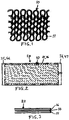
- Figure 1 shows a section of a heating mat 10 according to the invention, which is comprised of an electrically conductive wire 11 featuring an electrically insulated outer layer so that adjacent cross-wiring is possible without risk of short-circuiting.
- the heating mat 10 is produced through a knitting operation such as illustrated in figure 1 .
- the shape, size, knit pattern and mesh size of the mat can naturally vary according to need and preference.
- the desired performance of the heating mat naturally affects the choice of wire diameter and mesh size.
- the mesh size can also vary within any given heating mat based on need.
- the heating mat 10 can also be produced in an alternative embodiment through a crocheting operation using an electrically conductive wire 11 that features an electrically insulated outer layer so that adjacent cross-wiring is possible without a risk of short-circuiting.
- the size, shape and crochet pattern of the mat 10 can naturally vary according to needs and preference. The same conditions as in the above described knit variation are applicable with respect to wire selection, mesh size, etc. If the heating mat 10 is made with double wire, then two circuits, or alternatively a back-up circuit, are possible. Here, too, mesh size may vary within any given heating mat according to need.
- Ribbon and insulated electrically conductive wire can also be used in the knitting and crocheting under the abovementioned conditions.
- FIG. 2 shows a schematic depiction of a heating mat 10 constructed according to one of the above alternatives, arranged between two carrier layers 15, 16 of an incompletely cured thermoset plastic, which may be reinforced with suitable reinforcement material.
- the thermoset plastic may be comprised of, for example, polyester, epoxy plastic or polyurethane, and any reinforcement may be of glass fiber or other suitable fibers. Glass-fiber reinforced epoxy plastic has been found to be particularly appropriate.
- the incompletely cured carrier layers 15, 16 achieve an adhesion of the heating mat 10 so that they form a cohesive unit with formability/flexibility such that it can be stored rolled or folded. It is thereby advantageous to temporarily affix one or more temporary protective foils (not shown) to the side/sides of the carrier layer facing away from the heating mat to prevent sticking between carrier layers, such as during transport and subsequent handling.
- the mat unit 20 shown in figure 2 has been made into a cohesive unit through a certain degree of warming under simultaneous compression.
- the carrier layers 15, 16 show an overage in relation to the heating mat 10 at two opposing ends so as to form overhangs.
- the overhangs of carrier layer 15 are designated 35, 36 and the overhangs of carrier layer 16 are designated 46, 47.
- Figure 3 shows a partial cross-section through the mat unit 20 and here it should be mentioned that if necessary, extra epoxy films (not shown) can also be included in the mat unit 20 to achieve a good surface finish and good adhesion to the given wing.
- An epoxy film (not shown) can also be arranged between the heating mat 10 and one or both carrier layers. Any peel-off films (not shown) are removed prior to installation.
- Figure 5 shows an installation procedure according to the invention through placement of a mat unit 20 according to the invention on a rotor wing 50.
- a mat unit 20 is first positioned on the front edge of the wing 50, whereupon the protective foils are first removed. The mat unit 20 will thereby adhere to the surface of the blade.
- the connecting wires of the heating mat 10 are then connected to the wire appropriate for this purpose in a cable group 80, which is arranged along the rotor wing 50.
- a liner 70 which may be made from glass fiber reinforced epoxy plastic, for example, such as shown in figure 5 , is then applied, and on top of the liner a lightning conductor 90 is arranged.
- a flexible heating plate 100 divided into two sections 101, 102 which may be made, for example, from spring steel or a similarly flexible material with a thickness of approx. 0.5 mm, is then arranged.
- the plate sections 101, 102 contribute to proper levelling and a good surface finish of the mat unit 20 and nearby components, which helps contribute to a turbulence free transition to the wing 50 after completed curing and removal of the plate sections 101, 102. It shall be understood that the plate 100 in certain cases can also be made in a single piece or have additional divisions beyond what is shown here.
- a number of electrical heat sources are arranged, making it possible for the curing heat to be regulated as needed in the different areas.
- the heating mat 10 can also be involved in the curing process to ensure adequate curing, and sometimes may serve as the only heat source.
- the heating mat 10 can also be used for measuring temperature during curing.
- thermoset plastic parts 101, 102 are arranged with a certain overlap such as shown in figure 5 .
- tensioning device 110 such as in the form of a so-called vacuum bag sealed against the wing 50 and to vacuum-set the arrangement prior to the curing process in order to maximize contact between the sections of the heating plate and the underlying components. It shall be understood that alternative tensioning devices are possible within the framework of the invention.
- the vacuum bag 110 and the forming plate/curing plate 100 are removed, after which the results achieved are inspected and any necessary follow-up measures can be taken.
- the heating mat 10 can be divided into two different heating mats and mat units 20, whereby the dividing line between the two mat units runs preferably along the stagnation line 51 as defined by the stagnation point of the wing 50. It is thereby possible to design the two heating mats 10 with a small mesh size in their end area along the stagnation line to enable increased warmth.
- Figure 6 shows a rotor wing 50 fitted with the device according to the invention.
- the sections most prone to ice formation along the rotor wings in question 50 are according to the invention fitted with devices according to the invention.
- the heating mat's connecting wires are successively connected to the appropriate line in the cable group 80 during installation of the mat units 20 and preferably in such a way that the heating mats are connected in parallel to facilitate individual control. Serial connection is possible in certain cases.
- the lightning conductors 90 which are anchored in the liner 70 are successively spliced lengthwise when installing the mat units and connected to the existing lighting protection system.
- mesh size may vary within any given heating mat and be small in the section of the heating mat that will be in contact with the front part of the wing and stagnation point and larger in other parts of the heating mat. It shall be understood that several different mesh sizes can therefore occur within any given heating mat. Here it should also be mentioned that most ice formation usually occurs in the stagnation point.
- the shape, size and detailed design of the mat unit 20 can be adapted to prevailing needs, whereby it can, for example include more than one heating mat 10. Stacked heating mats are also possible with the addition of intermediate epoxy films, for example.
- a central computer is also arranged, which is configured for collection of, among other things, measurement data from each heating mat and for individual control of current flow or pulsed current to the heating mats. Wireless communication with two-way communications devices in the rotor wings is thereby established.
- the central computer thus monitors any ice formation on the rotor wings and directs the current pattern to the various heating mats. Any damages are also indicated.
- the central computer can in turn communicate remotely with a control room, for example.
- the invention therefore allows different levels of heating along a wing so as to enable absence of ice along the entire wing, which is a major advantage since cooling increases going towards the tip of the wing.
- curing usually takes place under use of pulsed current so that the intended curing temperature can be controlled to obtain adequate curing results.
- the curing process is monitored through pulsed current to the heating mats and resistance measurement.
- the pulsed currents will provide information on the wings's temperature during both monitoring and heating.
- a precipitation indicator can sometimes serve as an energy-saving add-on.
- a second lightning conductor can also be arranged on the side of the wing 50 opposite the lighting protection 90, which results in even better protection in the event of a lightning strike.
- the second lighting protector in the same way as lighting protector 90 in an equivalent liner 70, whereby the cable group 80 can be divided into two cable groups, which among other things is advantageous in heating mats divided along the stagnation line.
- the lightning conductors and cable groups are spliced afterwards as additional mat units 20 are arranged on the wing in question.
- the lightning conductors are anchored in the metal tip of the wing and connected to the rest of the lightning protection system in the wind power station.
- the design of the heating plate or plates must naturally be adapted to the abovementioned conditions.
- thermoset plastic film such as an epoxy film
- the need for heating plates can be reduced to the areas where the cable groups and lightning conductors are located. Other parts of the mat unit 20 can thereby be cured using the heating mat 10.
- the thermoset plastic film provides a good surface finish.
- each heating mat unit 20 offers the possibility for individual temperature measurement and individual heating during operation and also during downtime. Since heating can be adjusted to need along the length of the wing, substantial energy savings can be realized. This also allows for compensation of imbalance between different wings. Individual temperature measurement in each mat section/mat unit 20 therefore results in low power consumption and better de-icing.
- a major advantage of producing the heating mat 10 through a knitting or crocheting process is that the impact of temperature changes in the wire will not have any effect on the mat's outer dimensions.
Description
- The present invention relates to a method for the application of a number of heating mats on a wind power blade, according to
independent claim 1, and to an arrangement for measuring temperature and de-icing of wind power blades according to independent claim 3. - It is a problem to identify and/or prevent, when needed, the icing over of wings or rotor blades of wind power stations or wind turbines subject to a weather environment where there is a risk for icing.
- One purpose of the present invention is to achieve a method for ice detection, warming and de-icing of wings/rotor blades on wind power stations. Another purpose of the present invention is to achieve an attractive device that facilitates the procedure according to the invention. These objectives are achieved through the characteristics defined in the patient claims.
- Here it must be pointed out that the present invention is based on certain basic principles described in
WO 2015/105439 A1 , to which reference is made. According to the present invention a method and a device are achieved that facilitate a well-functioning application on, for example, rotor wings/blades of wind power stations or wind turbines. -
GB 599 617 - The invention allows an extremely advantageous alternative for the prevention of ice formation on wings according to the above and without the need for operational downtime because of ice formation. This results in substantial economic benefits. The device according to the invention can easily be applied to both wings already in service and newly manufactured wings. Preventative wing warming so that ice formation cannot even begin is also made possible by the invention. Ice detection is also made possible according to the invention. The invention presents many technical and economic benefits.
- Embodiments of the invention shall be described in greater detail in the following with respect to the attached drawings, on which
-
Figure 1 shows a schematic representation of a section of a heating mat in one embodiment, -
Figure 2 shows a schematic representation of an overhead view of a flexible mat unit according to the invention, where the two carrier layers are situated on either side of the heating mat, -
Figure 3 shows a schematic cross-section of a mat unit including two carrier layers, -
Figure 4 shows a schematic cross-section of a rotor wing before application of the device according to the invention, -
Figure 5 shows a schematic representation of the installation of the device according to the invention on the wing according tofigure 4 , and -
Figure 6 shows a schematic representation of the wing after completed installation. -
Figure 1 shows a section of aheating mat 10 according to the invention, which is comprised of an electricallyconductive wire 11 featuring an electrically insulated outer layer so that adjacent cross-wiring is possible without risk of short-circuiting. - The
heating mat 10 is produced through a knitting operation such as illustrated infigure 1 . It shall be understood that the shape, size, knit pattern and mesh size of the mat can naturally vary according to need and preference. One can use, for example, enameledcopper wire 11. The desired performance of the heating mat naturally affects the choice of wire diameter and mesh size. The mat depicted, which is single-wire, creates one electrical circuit. If the heating mat is knitted from double wire, two electrical circuits, or alternatively a back-up circuit, can be created. The mesh size can also vary within any given heating mat based on need. - The
heating mat 10 can also be produced in an alternative embodiment through a crocheting operation using an electricallyconductive wire 11 that features an electrically insulated outer layer so that adjacent cross-wiring is possible without a risk of short-circuiting. - It shall be understood that the size, shape and crochet pattern of the
mat 10 can naturally vary according to needs and preference. The same conditions as in the above described knit variation are applicable with respect to wire selection, mesh size, etc. If theheating mat 10 is made with double wire, then two circuits, or alternatively a back-up circuit, are possible. Here, too, mesh size may vary within any given heating mat according to need. - Ribbon and insulated electrically conductive wire can also be used in the knitting and crocheting under the abovementioned conditions.
-
Figure 2 shows a schematic depiction of aheating mat 10 constructed according to one of the above alternatives, arranged between twocarrier layers - The incompletely cured
carrier layers heating mat 10 so that they form a cohesive unit with formability/flexibility such that it can be stored rolled or folded. It is thereby advantageous to temporarily affix one or more temporary protective foils (not shown) to the side/sides of the carrier layer facing away from the heating mat to prevent sticking between carrier layers, such as during transport and subsequent handling. - The
mat unit 20 shown infigure 2 has been made into a cohesive unit through a certain degree of warming under simultaneous compression. - In the
mat unit 20 shown infigure 2 , thecarrier layers heating mat 10 at two opposing ends so as to form overhangs. The overhangs ofcarrier layer 15 are designated 35, 36 and the overhangs ofcarrier layer 16 are designated 46, 47. -
Figure 3 shows a partial cross-section through themat unit 20 and here it should be mentioned that if necessary, extra epoxy films (not shown) can also be included in themat unit 20 to achieve a good surface finish and good adhesion to the given wing. An epoxy film (not shown) can also be arranged between theheating mat 10 and one or both carrier layers. Any peel-off films (not shown) are removed prior to installation. -
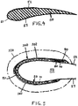
Figure 4 shows a cross-section of a rotor wing/blade 50, here, however, it shall be understood that the shape of a rotor blade may naturally vary, as may the cross-section size along a rotor blade. Therotor blade 50 shows a so-calledstagnation point 51, the approximate placement of which is indicated in the figure. On either side of the stagnation point theblade 50 features apressure side 52 and asuction side 53. -
Figure 5 shows an installation procedure according to the invention through placement of amat unit 20 according to the invention on arotor wing 50. - A
mat unit 20 is first positioned on the front edge of thewing 50, whereupon the protective foils are first removed. Themat unit 20 will thereby adhere to the surface of the blade. The connecting wires of theheating mat 10 are then connected to the wire appropriate for this purpose in acable group 80, which is arranged along therotor wing 50. Aliner 70, which may be made from glass fiber reinforced epoxy plastic, for example, such as shown infigure 5 , is then applied, and on top of the liner alightning conductor 90 is arranged. - A
flexible heating plate 100 divided into twosections plate sections mat unit 20 and nearby components, which helps contribute to a turbulence free transition to thewing 50 after completed curing and removal of theplate sections plate 100 in certain cases can also be made in a single piece or have additional divisions beyond what is shown here. - On the outsides of the
plate sections heating mat 10 can also be involved in the curing process to ensure adequate curing, and sometimes may serve as the only heat source. Theheating mat 10 can also be used for measuring temperature during curing. - In the example shown the thermoset
plastic parts figure 5 . - It is also advantageous to arrange a
tensioning device 110 such as in the form of a so-called vacuum bag sealed against thewing 50 and to vacuum-set the arrangement prior to the curing process in order to maximize contact between the sections of the heating plate and the underlying components. It shall be understood that alternative tensioning devices are possible within the framework of the invention. - The abovementioned curing possibilities thus allow for adequate and desirable curing results.
- Once the curing process is complete, the
vacuum bag 110 and the forming plate/curing plate 100 are removed, after which the results achieved are inspected and any necessary follow-up measures can be taken. - It is also possible to carry out simultaneous installation and curing of two or
more mat units 20 that are closely-spaced or bordering one another, whereby size adjustments of the forming- andcuring plate 100 and thevacuum bag 110 must be made. - According to another embodiment, the
heating mat 10 can be divided into two different heating mats andmat units 20, whereby the dividing line between the two mat units runs preferably along thestagnation line 51 as defined by the stagnation point of thewing 50. It is thereby possible to design the twoheating mats 10 with a small mesh size in their end area along the stagnation line to enable increased warmth. - This has, among other things, the advantage that the two heating mats can be more easily adapted to needs of the various ice formation conditions normally prevailing on the
pressure side 52 andsuction side 53 of thewing 50. Application and installation take place according to the principle described above and wiring is completed as necessary for the mat units to be individually controlled. - When using two separate mat units instead of one mat unit, these are connected along the stagnation line, such as by means of epoxy plastic. It shall be understood that further divisions of the heating mats and mat units are, of course, possible within the framework of the invention.
-
Figure 6 shows arotor wing 50 fitted with the device according to the invention. The sections most prone to ice formation along the rotor wings inquestion 50 are according to the invention fitted with devices according to the invention. - The heating mat's connecting wires are successively connected to the appropriate line in the
cable group 80 during installation of themat units 20 and preferably in such a way that the heating mats are connected in parallel to facilitate individual control. Serial connection is possible in certain cases. - The
lightning conductors 90 which are anchored in theliner 70 are successively spliced lengthwise when installing the mat units and connected to the existing lighting protection system. - By varying the mesh size in the knitted or crocheted
heating mats 10 it is possible to adapt the thermal output according to prevailing needs. Mesh size may vary within any given heating mat and be small in the section of the heating mat that will be in contact with the front part of the wing and stagnation point and larger in other parts of the heating mat. It shall be understood that several different mesh sizes can therefore occur within any given heating mat. Here it should also be mentioned that most ice formation usually occurs in the stagnation point. - From the above It shall be understood that the shape, size and detailed design of the
mat unit 20 can be adapted to prevailing needs, whereby it can, for example include more than oneheating mat 10. Stacked heating mats are also possible with the addition of intermediate epoxy films, for example. - With respect to de-icing, it is usually the most advantageous to heat attack in the area of the stagnation point/stagnation line, which is made possible by the present invention.
- The possibilities afforded by the invention, such as continuous temperature monitoring through individual resistance measurement in the heating mats, allow for significant energy savings in that it is possible to initiate blade warming in the correct stage and extent.
- In the event of a failure in a given heating mat on a rotor wing the corresponding heating mat on other rotor wings can be temporarily disabled in order to minimize imbalance.
- A central computer is also arranged, which is configured for collection of, among other things, measurement data from each heating mat and for individual control of current flow or pulsed current to the heating mats. Wireless communication with two-way communications devices in the rotor wings is thereby established.
- The central computer thus monitors any ice formation on the rotor wings and directs the current pattern to the various heating mats. Any damages are also indicated. The central computer can in turn communicate remotely with a control room, for example.
- The invention therefore allows different levels of heating along a wing so as to enable absence of ice along the entire wing, which is a major advantage since cooling increases going towards the tip of the wing.
- It should be noted that curing usually takes place under use of pulsed current so that the intended curing temperature can be controlled to obtain adequate curing results. The curing process is monitored through pulsed current to the heating mats and resistance measurement.
- During use of the device according to the invention the pulsed currents will provide information on the wings's temperature during both monitoring and heating. A precipitation indicator can sometimes serve as an energy-saving add-on.
- In an alternative embodiment, a second lightning conductor can also be arranged on the side of the
wing 50 opposite thelighting protection 90, which results in even better protection in the event of a lightning strike. In this case, it is advantageous to complete the application of the second lighting protector in the same way aslighting protector 90 in anequivalent liner 70, whereby thecable group 80 can be divided into two cable groups, which among other things is advantageous in heating mats divided along the stagnation line. The lightning conductors and cable groups are spliced afterwards asadditional mat units 20 are arranged on the wing in question. The lightning conductors are anchored in the metal tip of the wing and connected to the rest of the lightning protection system in the wind power station. - The design of the heating plate or plates must naturally be adapted to the abovementioned conditions.
- If a thermoset plastic film is applied, such as an epoxy film, on the side of the
mat unit 20 facing away from the wing, the need for heating plates can be reduced to the areas where the cable groups and lightning conductors are located. Other parts of themat unit 20 can thereby be cured using theheating mat 10. The thermoset plastic film provides a good surface finish. - According to the invention a large number of heating mat units (sections) 20 are arranged along the length of the
wing 50. Eachheating mat unit 20 offers the possibility for individual temperature measurement and individual heating during operation and also during downtime. Since heating can be adjusted to need along the length of the wing, substantial energy savings can be realized. This also allows for compensation of imbalance between different wings. Individual temperature measurement in each mat section/mat unit 20 therefore results in low power consumption and better de-icing. - It is also possible to adjust the size of the given
heating mat units 20 so as to facilitate any future repairs. - A major advantage of producing the
heating mat 10 through a knitting or crocheting process is that the impact of temperature changes in the wire will not have any effect on the mat's outer dimensions. - It is also possible to use more than two parallel wires, such as 5 wires, to adapt the heating performance of the mats to various operating conditions.
- The invention is therefore not limited to what has been illustrated and described; changes and modifications to the invention are naturally imaginable within the framework of the following patent claims.
Claims (6)
- Method for the application of a number of heating mats on a wind power station wing/blade for the purpose of achieving de-icing also during operation, where needed, characterized in that a heating mat (10) in question is first applied in the intended place on the wing (50) and that the necessary electrical connections are supplied, that at least one heating plate (100) is then applied on the heating mat (10) or in the proximity of the heating mat and a tensioning device (110) is arranged which surrounds the heating mat with surrounding parts, after which curing takes place after the tensioning device is activated and wherein the curing heat is generated by the heating plate (100) and via the heating mat (10) and wherein control of curing progress takes place through pulsed current to the heating mat unit (10).
- Method according to claim 1, characterized in that the heating mats (10) installed are used for temperature monitoring in the wing (50) and for de-icing the wing, whereby pulsed currents are used.
- Arrangement for measuring temperature and de-icing of wind power station wings/blades for the purpose of achieving de-icing during operation when necessary, the arrangement includes a number of heating mats (10) each integrated into its own mat unit (20), wherein each heating mat (10) is produced through knitting or crocheting of enameled metal wire, such as copper wire, characterized in that the mesh size vary within any given heating mat (10) and the mesh size is smaller in a section of the heating mat (10) that will be in contact with a stagnation point/stagnation line (51) of the wing (50) and larger in other parts of the heating mat (10).
- Arrangement according to claim 3, characterized in that the mat unit (20) includes two carrier layers (15, 16) that are arranged on different side of the heating mat (10).
- Arrangement according to any of claims 3-4, characterized in that the device includes at least one cover mat (70) for at least one cable group (80).
- Arrangement according to claim 5, characterized in that at least one lightning protector (90) is arranged on the outside of the cover mat (70) or cover mats.
Applications Claiming Priority (2)
| Application Number | Priority Date | Filing Date | Title |
|---|---|---|---|
| SE1700019 | 2017-02-06 | ||
| PCT/SE2018/000003 WO2018143860A1 (en) | 2017-02-06 | 2018-02-02 | Method and arrangement related to heating of wings in wind power plants or other devices |
Publications (3)
| Publication Number | Publication Date |
|---|---|
| EP3577340A1 EP3577340A1 (en) | 2019-12-11 |
| EP3577340A4 EP3577340A4 (en) | 2020-11-18 |
| EP3577340B1 true EP3577340B1 (en) | 2022-06-22 |
Family
ID=63039982
Family Applications (1)
| Application Number | Title | Priority Date | Filing Date |
|---|---|---|---|
| EP18747135.4A Active EP3577340B1 (en) | 2017-02-06 | 2018-02-02 | Method and arrangement related to heating of wings in wind power plants |
Country Status (7)
| Country | Link |
|---|---|
| US (1) | US11480157B2 (en) |
| EP (1) | EP3577340B1 (en) |
| CN (1) | CN110546378A (en) |
| CA (1) | CA3056400A1 (en) |
| DK (1) | DK3577340T3 (en) |
| ES (1) | ES2928948T3 (en) |
| WO (1) | WO2018143860A1 (en) |
Families Citing this family (7)
| Publication number | Priority date | Publication date | Assignee | Title |
|---|---|---|---|---|
| EP3581797A1 (en) * | 2018-06-12 | 2019-12-18 | Siemens Gamesa Renewable Energy A/S | Heating arrangement for bonding a protective shell to a wind turbine blade and method for bonding a protective shell to a wind turbine blade |
| EP3708828A1 (en) * | 2019-03-14 | 2020-09-16 | Siemens Gamesa Renewable Energy A/S | A method for providing a wind turbine blade with lightning protection and a wind turbine blade |
| JP6838181B1 (en) * | 2020-02-26 | 2021-03-03 | 三菱重工業株式会社 | Windmill wings |
| GB202006879D0 (en) * | 2020-05-11 | 2020-06-24 | Blade Dynamics Ltd | Leading edge protection for a wind turbine blade |
| JP2021183832A (en) * | 2020-05-22 | 2021-12-02 | 三菱重工業株式会社 | Windmill blade, windmill and method for manufacturing windmill blade |
| CN112629807B (en) * | 2021-03-09 | 2022-01-11 | 中国空气动力研究与发展中心低速空气动力研究所 | Method for removing ice growing on surface of silk thread hot knife and model |
| WO2023059254A1 (en) * | 2021-10-07 | 2023-04-13 | Kjell Lindskog | Method for preventing ice formation at a blade of a wind turbine |
Citations (2)
| Publication number | Priority date | Publication date | Assignee | Title |
|---|---|---|---|---|
| EP0983437B1 (en) * | 1997-05-20 | 2003-10-15 | Thermion Systems International | Device and method for heating and deicing wind energy turbine blades |
| US20160282288A1 (en) * | 2015-03-26 | 2016-09-29 | The Boeing Company | System and method to map a thermal profile of a composite structure using a thermochromatic witness assembly |
Family Cites Families (15)
| Publication number | Priority date | Publication date | Assignee | Title |
|---|---|---|---|---|
| GB599617A (en) * | 1944-12-28 | 1948-03-17 | Honorary Advisory Council Sci | Method of making electrically heated de-icing devices |
| FR2779314B1 (en) * | 1998-05-27 | 2000-08-04 | Eurocopter France | HEATING DEVICE WITH RESISTIVE ELEMENTS OF AN AERODYNAMIC PROFILE |
| US7291815B2 (en) * | 2006-02-24 | 2007-11-06 | Goodrich Corporation | Composite ice protection heater and method of producing same |
| WO2008013459A2 (en) | 2006-07-24 | 2008-01-31 | Ward, Robert, William | Textile articles incorporating an electrical heating element(s) |
| GB2453769B (en) * | 2007-10-18 | 2012-09-05 | Gkn Aerospace Services Ltd | An aircraft leading edge thermoplastic heating mat |
| US9415875B2 (en) * | 2010-04-12 | 2016-08-16 | Siemens Aktiengesellschaft | Heating mats arranged in a loop on a blade |
| FI20115536L (en) * | 2011-05-31 | 2013-03-25 | Teknologian Tutkimuskeskus Vtt Oy | Wind turbine blades and associated manufacturing method |
| EP2602455B1 (en) * | 2011-12-07 | 2015-02-11 | Nordex Energy GmbH | Wind energy assembly rotor blade with an electrical heating element |
| DK2607075T3 (en) * | 2011-12-22 | 2017-08-07 | Siemens Ag | Sandwich laminate and method of manufacture |
| JP5675673B2 (en) | 2012-02-29 | 2015-02-25 | 三菱重工業株式会社 | Fiber reinforced plastic heating element and wind power generator equipped with the heating element |
| US20140014776A1 (en) | 2012-07-13 | 2014-01-16 | Kelly Aerospace Thermal Systems Llc | System containing an electric heating element and method for installation and use thereof |
| EP2754891B1 (en) * | 2013-01-14 | 2017-05-17 | Siemens Aktiengesellschaft | Wind turbine rotor blade de-icing arrangement |
| CN106171042A (en) * | 2014-01-13 | 2016-11-30 | 谢尔·林斯科格 | For manufacturing product or the method and apparatus completing product |
| WO2016030170A1 (en) * | 2014-08-27 | 2016-03-03 | Basf Se | Rotor blade element with anti-icing surface for wind turbine rotor blades |
| CN105673361B (en) * | 2015-12-31 | 2018-07-13 | 东方电气风电有限公司 | Ice-melt heating structure of blade of wind-driven generator and preparation method thereof |
-
2018
- 2018-02-02 WO PCT/SE2018/000003 patent/WO2018143860A1/en active Application Filing
- 2018-02-02 CN CN201880017441.9A patent/CN110546378A/en active Pending
- 2018-02-02 DK DK18747135.4T patent/DK3577340T3/en active
- 2018-02-02 US US16/483,202 patent/US11480157B2/en active Active
- 2018-02-02 CA CA3056400A patent/CA3056400A1/en active Pending
- 2018-02-02 ES ES18747135T patent/ES2928948T3/en active Active
- 2018-02-02 EP EP18747135.4A patent/EP3577340B1/en active Active
Patent Citations (2)
| Publication number | Priority date | Publication date | Assignee | Title |
|---|---|---|---|---|
| EP0983437B1 (en) * | 1997-05-20 | 2003-10-15 | Thermion Systems International | Device and method for heating and deicing wind energy turbine blades |
| US20160282288A1 (en) * | 2015-03-26 | 2016-09-29 | The Boeing Company | System and method to map a thermal profile of a composite structure using a thermochromatic witness assembly |
Also Published As
| Publication number | Publication date |
|---|---|
| CA3056400A1 (en) | 2018-08-09 |
| US11480157B2 (en) | 2022-10-25 |
| CN110546378A (en) | 2019-12-06 |
| EP3577340A4 (en) | 2020-11-18 |
| EP3577340A1 (en) | 2019-12-11 |
| ES2928948T3 (en) | 2022-11-23 |
| US20200232445A1 (en) | 2020-07-23 |
| WO2018143860A1 (en) | 2018-08-09 |
| DK3577340T3 (en) | 2022-08-29 |
Similar Documents
| Publication | Publication Date | Title |
|---|---|---|
| EP3577340B1 (en) | Method and arrangement related to heating of wings in wind power plants | |
| EP3095296B1 (en) | Method and arrangement for manufacture of a product or completion of a product | |
| WO2011127997A1 (en) | Heating mats arranged in a loop on a blade | |
| EP2526292B1 (en) | Fixation of a heating mat to a blade of a wind turbine | |
| US10522992B2 (en) | Thermal snow and ice prevention system for bridge cables | |
| RU2591369C2 (en) | Wind turbine blade and method for manufacturing said blade | |
| DK2597305T3 (en) | Wind turbine rotor blade with a heating means and method for producing the same | |
| EP2526293A1 (en) | Controlling of a heating mat on a blade of a wind turbine | |
| CN102878026B (en) | Wind driven generator rotor blade with electrothermal deicing devices | |
| CN103147931A (en) | Wind turbine rotor blade with electrical heating element | |
| EP0983437A1 (en) | Device and method for heating and deicing wind energy turbine blades | |
| WO2007136260A1 (en) | Heated aerodynamic profile for composite structures | |
| CN107134740A (en) | The anti-icing method and system of extra high voltage direct current transmission line on-load | |
| CN112882130A (en) | City meteorological monitoring equipment | |
| CN112922792B (en) | Blade electrothermal composite film, blade, wind generating set and method for manufacturing blade | |
| CN105761837A (en) | Optical fiber composite overhead ground wire with fast ice melting function | |
| WO2020027709A1 (en) | Arrangement and method for warming of blades/wings at wind power plants and similar devices | |
| EP3530937B1 (en) | Electric heating module structure, installation method and forming method thereof, and wind turbine | |
| CN111963393A (en) | Blade electric heating device, blade, wind generating set and blade ice melting method | |
| CN206349177U (en) | It is a kind of can ice-melt built on stilts lightning protection two-conductor Ground wire with insulation ocver | |
| CN113700617A (en) | Blade tip anti-icing and deicing device of horizontal axis wind generating set and installation method | |
| CA3234024A1 (en) | Method for preventing ice formation at a blade of a wind turbine |
Legal Events
| Date | Code | Title | Description |
|---|---|---|---|
| STAA | Information on the status of an ep patent application or granted ep patent |
Free format text: STATUS: THE INTERNATIONAL PUBLICATION HAS BEEN MADE |
|
| PUAI | Public reference made under article 153(3) epc to a published international application that has entered the european phase |
Free format text: ORIGINAL CODE: 0009012 |
|
| STAA | Information on the status of an ep patent application or granted ep patent |
Free format text: STATUS: REQUEST FOR EXAMINATION WAS MADE |
|
| 17P | Request for examination filed |
Effective date: 20190806 |
|
| AK | Designated contracting states |
Kind code of ref document: A1 Designated state(s): AL AT BE BG CH CY CZ DE DK EE ES FI FR GB GR HR HU IE IS IT LI LT LU LV MC MK MT NL NO PL PT RO RS SE SI SK SM TR |
|
| A4 | Supplementary search report drawn up and despatched |
Effective date: 20201019 |
|
| RIC1 | Information provided on ipc code assigned before grant |
Ipc: H05B 3/28 20060101ALI20201013BHEP Ipc: B32B 37/06 20060101ALI20201013BHEP Ipc: B32B 37/10 20060101ALI20201013BHEP Ipc: F03D 80/40 20160101AFI20201013BHEP Ipc: B64D 15/12 20060101ALI20201013BHEP Ipc: B29C 35/02 20060101ALI20201013BHEP |
|
| STAA | Information on the status of an ep patent application or granted ep patent |
Free format text: STATUS: EXAMINATION IS IN PROGRESS |
|
| 17Q | First examination report despatched |
Effective date: 20210507 |
|
| REG | Reference to a national code |
Ref country code: DE Ref legal event code: R079 Ref document number: 602018037030 Country of ref document: DE Free format text: PREVIOUS MAIN CLASS: F03D0080400000 Ipc: B29C0065720000 |
|
| GRAP | Despatch of communication of intention to grant a patent |
Free format text: ORIGINAL CODE: EPIDOSNIGR1 |
|
| STAA | Information on the status of an ep patent application or granted ep patent |
Free format text: STATUS: GRANT OF PATENT IS INTENDED |
|
| RIC1 | Information provided on ipc code assigned before grant |
Ipc: B29C 65/34 20060101ALI20220131BHEP Ipc: B29C 65/72 20060101AFI20220131BHEP |
|
| INTG | Intention to grant announced |
Effective date: 20220225 |
|
| GRAS | Grant fee paid |
Free format text: ORIGINAL CODE: EPIDOSNIGR3 |
|
| GRAA | (expected) grant |
Free format text: ORIGINAL CODE: 0009210 |
|
| STAA | Information on the status of an ep patent application or granted ep patent |
Free format text: STATUS: THE PATENT HAS BEEN GRANTED |
|
| AK | Designated contracting states |
Kind code of ref document: B1 Designated state(s): AL AT BE BG CH CY CZ DE DK EE ES FI FR GB GR HR HU IE IS IT LI LT LU LV MC MK MT NL NO PL PT RO RS SE SI SK SM TR |
|
| REG | Reference to a national code |
Ref country code: GB Ref legal event code: FG4D |
|
| REG | Reference to a national code |
Ref country code: CH Ref legal event code: EP |
|
| REG | Reference to a national code |
Ref country code: DE Ref legal event code: R096 Ref document number: 602018037030 Country of ref document: DE |
|
| REG | Reference to a national code |
Ref country code: AT Ref legal event code: REF Ref document number: 1499511 Country of ref document: AT Kind code of ref document: T Effective date: 20220715 |
|
| REG | Reference to a national code |
Ref country code: IE Ref legal event code: FG4D |
|
| REG | Reference to a national code |
Ref country code: DK Ref legal event code: T3 Effective date: 20220824 |
|
| REG | Reference to a national code |
Ref country code: SE Ref legal event code: TRGR |
|
| REG | Reference to a national code |
Ref country code: LT Ref legal event code: MG9D |
|
| REG | Reference to a national code |
Ref country code: NL Ref legal event code: MP Effective date: 20220622 |
|
| PG25 | Lapsed in a contracting state [announced via postgrant information from national office to epo] |
Ref country code: NO Free format text: LAPSE BECAUSE OF FAILURE TO SUBMIT A TRANSLATION OF THE DESCRIPTION OR TO PAY THE FEE WITHIN THE PRESCRIBED TIME-LIMIT Effective date: 20220922 Ref country code: LT Free format text: LAPSE BECAUSE OF FAILURE TO SUBMIT A TRANSLATION OF THE DESCRIPTION OR TO PAY THE FEE WITHIN THE PRESCRIBED TIME-LIMIT Effective date: 20220622 Ref country code: HR Free format text: LAPSE BECAUSE OF FAILURE TO SUBMIT A TRANSLATION OF THE DESCRIPTION OR TO PAY THE FEE WITHIN THE PRESCRIBED TIME-LIMIT Effective date: 20220622 Ref country code: GR Free format text: LAPSE BECAUSE OF FAILURE TO SUBMIT A TRANSLATION OF THE DESCRIPTION OR TO PAY THE FEE WITHIN THE PRESCRIBED TIME-LIMIT Effective date: 20220923 Ref country code: FI Free format text: LAPSE BECAUSE OF FAILURE TO SUBMIT A TRANSLATION OF THE DESCRIPTION OR TO PAY THE FEE WITHIN THE PRESCRIBED TIME-LIMIT Effective date: 20220622 Ref country code: BG Free format text: LAPSE BECAUSE OF FAILURE TO SUBMIT A TRANSLATION OF THE DESCRIPTION OR TO PAY THE FEE WITHIN THE PRESCRIBED TIME-LIMIT Effective date: 20220922 |
|
| REG | Reference to a national code |
Ref country code: AT Ref legal event code: MK05 Ref document number: 1499511 Country of ref document: AT Kind code of ref document: T Effective date: 20220622 |
|
| REG | Reference to a national code |
Ref country code: ES Ref legal event code: FG2A Ref document number: 2928948 Country of ref document: ES Kind code of ref document: T3 Effective date: 20221123 |
|
| PG25 | Lapsed in a contracting state [announced via postgrant information from national office to epo] |
Ref country code: RS Free format text: LAPSE BECAUSE OF FAILURE TO SUBMIT A TRANSLATION OF THE DESCRIPTION OR TO PAY THE FEE WITHIN THE PRESCRIBED TIME-LIMIT Effective date: 20220622 Ref country code: LV Free format text: LAPSE BECAUSE OF FAILURE TO SUBMIT A TRANSLATION OF THE DESCRIPTION OR TO PAY THE FEE WITHIN THE PRESCRIBED TIME-LIMIT Effective date: 20220622 |
|
| PG25 | Lapsed in a contracting state [announced via postgrant information from national office to epo] |
Ref country code: NL Free format text: LAPSE BECAUSE OF FAILURE TO SUBMIT A TRANSLATION OF THE DESCRIPTION OR TO PAY THE FEE WITHIN THE PRESCRIBED TIME-LIMIT Effective date: 20220622 |
|
| PG25 | Lapsed in a contracting state [announced via postgrant information from national office to epo] |
Ref country code: SM Free format text: LAPSE BECAUSE OF FAILURE TO SUBMIT A TRANSLATION OF THE DESCRIPTION OR TO PAY THE FEE WITHIN THE PRESCRIBED TIME-LIMIT Effective date: 20220622 Ref country code: SK Free format text: LAPSE BECAUSE OF FAILURE TO SUBMIT A TRANSLATION OF THE DESCRIPTION OR TO PAY THE FEE WITHIN THE PRESCRIBED TIME-LIMIT Effective date: 20220622 Ref country code: RO Free format text: LAPSE BECAUSE OF FAILURE TO SUBMIT A TRANSLATION OF THE DESCRIPTION OR TO PAY THE FEE WITHIN THE PRESCRIBED TIME-LIMIT Effective date: 20220622 Ref country code: PT Free format text: LAPSE BECAUSE OF FAILURE TO SUBMIT A TRANSLATION OF THE DESCRIPTION OR TO PAY THE FEE WITHIN THE PRESCRIBED TIME-LIMIT Effective date: 20221024 Ref country code: EE Free format text: LAPSE BECAUSE OF FAILURE TO SUBMIT A TRANSLATION OF THE DESCRIPTION OR TO PAY THE FEE WITHIN THE PRESCRIBED TIME-LIMIT Effective date: 20220622 Ref country code: CZ Free format text: LAPSE BECAUSE OF FAILURE TO SUBMIT A TRANSLATION OF THE DESCRIPTION OR TO PAY THE FEE WITHIN THE PRESCRIBED TIME-LIMIT Effective date: 20220622 Ref country code: AT Free format text: LAPSE BECAUSE OF FAILURE TO SUBMIT A TRANSLATION OF THE DESCRIPTION OR TO PAY THE FEE WITHIN THE PRESCRIBED TIME-LIMIT Effective date: 20220622 |
|
| PG25 | Lapsed in a contracting state [announced via postgrant information from national office to epo] |
Ref country code: PL Free format text: LAPSE BECAUSE OF FAILURE TO SUBMIT A TRANSLATION OF THE DESCRIPTION OR TO PAY THE FEE WITHIN THE PRESCRIBED TIME-LIMIT Effective date: 20220622 Ref country code: IS Free format text: LAPSE BECAUSE OF FAILURE TO SUBMIT A TRANSLATION OF THE DESCRIPTION OR TO PAY THE FEE WITHIN THE PRESCRIBED TIME-LIMIT Effective date: 20221022 |
|
| REG | Reference to a national code |
Ref country code: DE Ref legal event code: R097 Ref document number: 602018037030 Country of ref document: DE |
|
| PG25 | Lapsed in a contracting state [announced via postgrant information from national office to epo] |
Ref country code: AL Free format text: LAPSE BECAUSE OF FAILURE TO SUBMIT A TRANSLATION OF THE DESCRIPTION OR TO PAY THE FEE WITHIN THE PRESCRIBED TIME-LIMIT Effective date: 20220622 |
|
| PGFP | Annual fee paid to national office [announced via postgrant information from national office to epo] |
Ref country code: ES Payment date: 20230316 Year of fee payment: 6 Ref country code: DK Payment date: 20230215 Year of fee payment: 6 |
|
| PLBE | No opposition filed within time limit |
Free format text: ORIGINAL CODE: 0009261 |
|
| STAA | Information on the status of an ep patent application or granted ep patent |
Free format text: STATUS: NO OPPOSITION FILED WITHIN TIME LIMIT |
|
| 26N | No opposition filed |
Effective date: 20230323 |
|
| PGFP | Annual fee paid to national office [announced via postgrant information from national office to epo] |
Ref country code: TR Payment date: 20230117 Year of fee payment: 6 Ref country code: SE Payment date: 20230216 Year of fee payment: 6 Ref country code: DE Payment date: 20230217 Year of fee payment: 6 |
|
| PG25 | Lapsed in a contracting state [announced via postgrant information from national office to epo] |
Ref country code: SI Free format text: LAPSE BECAUSE OF FAILURE TO SUBMIT A TRANSLATION OF THE DESCRIPTION OR TO PAY THE FEE WITHIN THE PRESCRIBED TIME-LIMIT Effective date: 20220622 |
|
| PG25 | Lapsed in a contracting state [announced via postgrant information from national office to epo] |
Ref country code: MC Free format text: LAPSE BECAUSE OF FAILURE TO SUBMIT A TRANSLATION OF THE DESCRIPTION OR TO PAY THE FEE WITHIN THE PRESCRIBED TIME-LIMIT Effective date: 20220622 |
|
| REG | Reference to a national code |
Ref country code: CH Ref legal event code: PL |
|
| P01 | Opt-out of the competence of the unified patent court (upc) registered |
Effective date: 20230906 |
|
| REG | Reference to a national code |
Ref country code: BE Ref legal event code: MM Effective date: 20230228 |
|
| GBPC | Gb: european patent ceased through non-payment of renewal fee |
Effective date: 20230202 |
|
| PG25 | Lapsed in a contracting state [announced via postgrant information from national office to epo] |
Ref country code: LU Free format text: LAPSE BECAUSE OF NON-PAYMENT OF DUE FEES Effective date: 20230202 Ref country code: LI Free format text: LAPSE BECAUSE OF NON-PAYMENT OF DUE FEES Effective date: 20230228 Ref country code: CH Free format text: LAPSE BECAUSE OF NON-PAYMENT OF DUE FEES Effective date: 20230228 |
|
| REG | Reference to a national code |
Ref country code: IE Ref legal event code: MM4A |
|
| P02 | Opt-out of the competence of the unified patent court (upc) changed |
Effective date: 20231204 |
|
| PG25 | Lapsed in a contracting state [announced via postgrant information from national office to epo] |
Ref country code: GB Free format text: LAPSE BECAUSE OF NON-PAYMENT OF DUE FEES Effective date: 20230202 |
|
| PG25 | Lapsed in a contracting state [announced via postgrant information from national office to epo] |
Ref country code: IT Free format text: LAPSE BECAUSE OF FAILURE TO SUBMIT A TRANSLATION OF THE DESCRIPTION OR TO PAY THE FEE WITHIN THE PRESCRIBED TIME-LIMIT Effective date: 20220622 Ref country code: IE Free format text: LAPSE BECAUSE OF NON-PAYMENT OF DUE FEES Effective date: 20230202 Ref country code: GB Free format text: LAPSE BECAUSE OF NON-PAYMENT OF DUE FEES Effective date: 20230202 Ref country code: FR Free format text: LAPSE BECAUSE OF NON-PAYMENT OF DUE FEES Effective date: 20230228 |
|
| PG25 | Lapsed in a contracting state [announced via postgrant information from national office to epo] |
Ref country code: BE Free format text: LAPSE BECAUSE OF NON-PAYMENT OF DUE FEES Effective date: 20230228 |