EP3577263B1 - Woven sleeve with integral attachment loops and method of construction thereof - Google Patents
Woven sleeve with integral attachment loops and method of construction thereof Download PDFInfo
- Publication number
- EP3577263B1 EP3577263B1 EP18706029.8A EP18706029A EP3577263B1 EP 3577263 B1 EP3577263 B1 EP 3577263B1 EP 18706029 A EP18706029 A EP 18706029A EP 3577263 B1 EP3577263 B1 EP 3577263B1
- Authority
- EP
- European Patent Office
- Prior art keywords
- another
- wall
- bulky
- fluffy
- filaments
- Prior art date
- Legal status (The legal status is an assumption and is not a legal conclusion. Google has not performed a legal analysis and makes no representation as to the accuracy of the status listed.)
- Active
Links
Images

Classifications
-
- D—TEXTILES; PAPER
- D03—WEAVING
- D03D—WOVEN FABRICS; METHODS OF WEAVING; LOOMS
- D03D1/00—Woven fabrics designed to make specified articles
- D03D1/0035—Protective fabrics
- D03D1/0043—Protective fabrics for elongated members, i.e. sleeves
-
- A—HUMAN NECESSITIES
- A44—HABERDASHERY; JEWELLERY
- A44B—BUTTONS, PINS, BUCKLES, SLIDE FASTENERS, OR THE LIKE
- A44B18/00—Fasteners of the touch-and-close type; Making such fasteners
-
- D—TEXTILES; PAPER
- D03—WEAVING
- D03D—WOVEN FABRICS; METHODS OF WEAVING; LOOMS
- D03D15/00—Woven fabrics characterised by the material, structure or properties of the fibres, filaments, yarns, threads or other warp or weft elements used
- D03D15/20—Woven fabrics characterised by the material, structure or properties of the fibres, filaments, yarns, threads or other warp or weft elements used characterised by the material of the fibres or filaments constituting the yarns or threads
- D03D15/283—Woven fabrics characterised by the material, structure or properties of the fibres, filaments, yarns, threads or other warp or weft elements used characterised by the material of the fibres or filaments constituting the yarns or threads synthetic polymer-based, e.g. polyamide or polyester fibres
-
- D—TEXTILES; PAPER
- D03—WEAVING
- D03D—WOVEN FABRICS; METHODS OF WEAVING; LOOMS
- D03D15/00—Woven fabrics characterised by the material, structure or properties of the fibres, filaments, yarns, threads or other warp or weft elements used
- D03D15/40—Woven fabrics characterised by the material, structure or properties of the fibres, filaments, yarns, threads or other warp or weft elements used characterised by the structure of the yarns or threads
- D03D15/49—Woven fabrics characterised by the material, structure or properties of the fibres, filaments, yarns, threads or other warp or weft elements used characterised by the structure of the yarns or threads textured; curled; crimped
-
- D—TEXTILES; PAPER
- D03—WEAVING
- D03D—WOVEN FABRICS; METHODS OF WEAVING; LOOMS
- D03D23/00—General weaving methods not special to the production of any particular woven fabric or the use of any particular loom; Weaves not provided for in any other single group
-
- H—ELECTRICITY
- H02—GENERATION; CONVERSION OR DISTRIBUTION OF ELECTRIC POWER
- H02G—INSTALLATION OF ELECTRIC CABLES OR LINES, OR OF COMBINED OPTICAL AND ELECTRIC CABLES OR LINES
- H02G3/00—Installations of electric cables or lines or protective tubing therefor in or on buildings, equivalent structures or vehicles
- H02G3/02—Details
- H02G3/04—Protective tubing or conduits, e.g. cable ladders or cable troughs
-
- D—TEXTILES; PAPER
- D10—INDEXING SCHEME ASSOCIATED WITH SUBLASSES OF SECTION D, RELATING TO TEXTILES
- D10B—INDEXING SCHEME ASSOCIATED WITH SUBLASSES OF SECTION D, RELATING TO TEXTILES
- D10B2403/00—Details of fabric structure established in the fabric forming process
- D10B2403/01—Surface features
- D10B2403/011—Dissimilar front and back faces
- D10B2403/0111—One hairy surface, e.g. napped or raised
Definitions
- This invention relates generally to textile sleeves for protecting elongate members, and more particularly to textile sleeves configured for attachment to support member.
- Wires are commonly bundled together and protected by textile sleeves in the form of a wire harness.
- the wire harness is often fixed to an external support member, such as a vehicle frame member or some other vehicle component to maintain the wire harness in a fixed location.
- supplemental members separate from the wire harness, are used to fix the wire harness in location, such as clips, adhesives, plastic ties, and separately provided hook and loop fasteners, wherein one of the hook or loop portions is fixed via a secondary operation, such as via stitching or adhesive, to an external surface of the sleeve for fixation to the other of the hook or loop that is fixed to the desired support member.
- Document US 5300337 A describes an example of tubes with closure means comprising multifilament, bulky yarn interlaced in a sleeving material and relatively unconfined along one of its marginal edges and of Velcro® brand hook tape or similar hook type elements disposed along the other marginal edge.
- a sleeve constructed in accordance with the disclosure herein overcomes at least the drawbacks discussed above.
- a wrappable textile sleeve for protecting an elongate member includes a plurality of warp filaments and at least one weft filament woven with one another to form a woven wall.
- the woven wall has opposite sides extending lengthwise between opposite ends. The opposite sides are wrappable about a central longitudinal axis into overlapping relation with one another to bound the elongate member within a cavity of the sleeve.
- At least one warp and/or weft filament is provided as a bulky, fluffy multifilament, wherein the bulky, fluffy multifilament is woven to form at least one float extending over 2 or more weft and/or warp yarns, wherein the at least one float provides loops sufficient to readily fix themselves to hooks of a standard hook and loop fastener.
- a plurality of the warp filaments are provided as a bulky, fluffy multifilaments adjacent one another, with the adjacent bulky, fluffy multifilaments forming floats adjacent one another.
- a plurality of the weft filaments are provided as a bulky, fluffy multifilaments adjacent one another, with the adjacent bulky, fluffy multifilaments forming floats adjacent one another.
- the floats can be formed having a twill pattern.
- the floats can be formed having a satin pattern.
- the floats can be formed to extend over only a portion of the length of the wall.
- the floats can be formed to extend over only a portion of the circumference of the wall.
- the floats can be formed to extend over a full length of the wall.
- the floats can be formed to extend over a full circumference of the wall.
- At least some of the warp filaments can be provided as monofilaments.
- weft filaments can be provided as heat-settable monofilaments to be heat-set and bias the opposite sides into overlapping relation with one another to facilitate assembly of the sleeve about the elongate member.
- the warp filaments are woven over a plurality of dents, wherein a plurality of the dents each include a plurality of filaments, with at least one of the plurality of filaments including a bulky, fluffy multifilament.
- At least one of the plurality of filaments in each of the plurality of dents is a standard multifilament having a denier greater than the denier of the bulky, fluffy multifilament.
- the bulky, fluffy multifilament can be woven in a satin weave pattern and the standard multifilament within the same dent as the bulky, fluffy multifilament can be woven in a plain weave pattern.
- the denier of the bulky, fluffy multifilament is between about 210-250tex.
- the denier of the standard multifilament is about 1400Dtex.
- a method of constructing a wrappable textile sleeve for protecting an elongate member includes weaving a plurality of warp filaments and at least one weft filament with one another to form a woven wall. The method further includes weaving the wall having opposite sides extending lengthwise between opposite ends, with the opposite sides being wrappable about a central longitudinal axis into overlapping relation with one another to bound the elongate member within a cavity of the sleeve.
- the method further includes weaving at least one warp and/or weft filament as a bulky, fluffy multifilament, and weaving the bulky, fluffy multifilament to form at least one float extending over 2 or more weft and/or warp yarns, with the at least one float providing loops sufficient to readily fix themselves to hooks of a standard hook and loop fastener.
- the method can further include weaving a plurality of the warp filaments as bulky, fluffy multifilaments adjacent one another, and weaving the adjacent bulky, fluffy multifilaments having floats adjacent one another to provide an increased surface area of loops configured to interlock with hooks as a hook-and-loop type fastener.
- the method can further include weaving a plurality of the weft filaments as bulky, fluffy multifilaments adjacent one another, and weaving the adjacent bulky, fluffy multifilaments forming floats adjacent one another.
- the method can further include weaving the floats in a twill pattern.
- the method can further include weaving the floats having a satin pattern.
- the method can further include weaving the floats to extend over only a portion of the length of the wall.
- the method can further include weaving the floats to extend over only a portion of the circumference of the wall.
- the method can further include weaving the floats to extend over a full length of the wall.
- the method can further include weaving the floats to extend over a full circumference of the wall.
- the method can further include weaving at least some of the warp filaments as monofilaments to enhance the abrasion resistance of the sleeve.
- the method can further include heat-setting at least some of the weft filaments to bias the opposite sides into overlapping relation with one another.
- the method can further include weaving the warp filaments over a plurality of dents and providing a plurality of the dents each including a plurality of filaments, with at least one of the plurality of filaments within at least some of the dents including the bulky, fluffy multifilament.
- the method can further include providing at least one of the plurality of filaments within each of the dents as a standard multifilament having a denier greater than the denier of the bulky, fluffy multifilament.
- the method can further include weaving the bulky, fluffy multifilament in a satin weave pattern and weaving the standard multifilament in a plain weave pattern within the same dent.
- the method can further include providing the denier of the bulky, fluffy multifilament being between about 210-250tex.
- the method can further include providing the denier of the standard multifilament being about 140tex +/-5%.
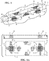
- Figures 1 and 1A show schematically a wrappable, protective sleeve, referred to hereafter simply as sleeve 10, constructed in accordance with one presently preferred, non-limiting embodiment of the disclosure, wherein, as shown in Figure 1 , the wall 16 is constructed to be releasably fixed to a support member 32.
- the sleeve 10 includes a plurality of warp yarns, also referred to as warp filaments 12, and at least one or a plurality of weft yarns, also referred to as weft filaments 14, woven with one another to form a woven substrate, also referred to simply as wall 16.
- the wall 16 has opposite sides 18, 20 configured to be wrapped about a central longitudinal axis 22 into overlapping relation with one another to bound an elongate member 28 to be protected within a circumferentially enclosed cavity 30 of the sleeve 10, with the opposite sides 18, 20 shown extending lengthwise generally parallel to the central longitudinal axis 22 between opposite open ends 24, 26.
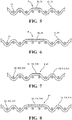
- At least one warp and/or weft filament 12, 14, and shown in the non-limiting embodiment of Figures 1 and 1A as being a plurality of warp filaments 12, is provided as a bulky, fluffy multifilament 33, wherein each bulky, fluffy multifilament 33 is woven to form at least one float 34 extending over 2 ( Figure 5 ) or more ( Figure 6 ) weft and/or warp yarns 12, 14, wherein the at least one float 34 provides loops 36 sufficient to readily fix themselves to hooks 38 of a hook portion 40 of a standard hook and loop fastener, such as sometimes purchased under the name Velcro®.
- the sleeve 10 is able to be releasably fixed to the support member 32 without need of having to fix a separate loop fastener portion to the wall 16, as the loops 36 integrally woven into the wall 16 of the sleeve 10 already form a loop fastener portion, also referred to as fastener patch P, integral to the sleeve 10 as woven.
- the sleeve 10 can be constructed as a self-wrapping sleeve, such that the wall 16 is automatically biased to curl about the central longitudinal axis 22 to bring the opposite sides 18, 20 into their overlapping relation.
- the self-wrapping bias can be imparted within the wall 16 of the sleeve 10 via heat-setting at least one weft filament 14 or a plurality of weft filaments 14.
- At least one or a plurality of the weft filaments 14 can be provided as a heat-settable polymeric filament or filaments, wherein the heat-settable weft filament or filaments 14, whether some of all, are preferably monofilaments of a heat-settable thermoplastic, such as, by way of example and without limitation, polyester, thereby allowing the sleeve 10 to be heat-set or otherwise biased into a tubular form.
- a heat-settable thermoplastic such as, by way of example and without limitation, polyester
- a plurality of the warp filaments 12 are provided as bulky, fluffy multifilaments 33.
- the plurality of warp multifilaments 33 can be woven in immediately adjacent, contiguous relation one another with floats 34 also being formed adjacent and contiguous one another, such that the floats 34 are aligned with one another along a circumferential direction.
- an increased size fastener patch P of the loops 36 in comparison to that as would be formed by s single bulky, fluffy multifilament 33, is formed for attachment to the hook portion 40.
- the warp floats 34 extend over a plurality of adjacent weft filaments, and in accordance one aspect of the invention, the floats 34 can be formed having a twill pattern ( Figure 5 ) or satin pattern ( Figure 6 ), wherein, as will be understood by a skilled artisan of the textile arts, the satin pattern would form a longer lengthwise extending fastener patch P of loops 36 than a twill pattern.
- the respective patches P can be formed in immediate succession with one another to form increased size patches P.
- the warp floats 34 and fastener patch(es) P formed thereby can be formed to extend over only a portion of the length of the wall 16, in the select, desired location of the wall 16 to be attached to the support member 32, or as shown and discussed hereafter, the patch P can be formed in immediately adjacent relation with one another to extend over a full length of the wall 14, depending on the application and the size and location of the hook portion 40 to which the loops 36 will be attached.
- a pair of fastener patches P is formed in over select regions of the wall 16 in predetermined axially spaced relation from one another, and in axial, lengthwise alignment with one another, such that the fastener patches P are automatically located for alignment with and releasable fixation to a pair or more of similarly spaced, corresponding hook portions 40. It is to be recognized that although a pair of the fastener patches P are shown, any desired number of fastener patches P could be formed along the length of the sleeve 10.
- the fastener patches P are shown as being formed as discrete islands spaced from one another in lengthwise alignment with one another and spaced from the opposite sides 18, 20 and from the opposite ends 24, 26.
- each fastener patch P can be precisely controlled in manufacture to ensure the fastener patches P are sized and located for subsequent releasable fixation to the hook portion(s) 40.
- the fastener patches P are formed with warp floats 34, the remaining portion of the wall 16 can be woven via any desired weave pattern, such as a plain weave pattern or otherwise, as desired.
- any type of non-fluffy warp yarn including monofilament and/or multifilament, can be used in the regions not including the fastener patches P, and thus, the physical properties of the wall 16 on opposite sides of the fastener patches P can be provided as desired, depending on the type of warp 12 and weft yarns 14 used.
- a sleeve 110 is shown in accordance with another non-limiting embodiment of the disclosure, wherein the same reference numerals as used above, offset by a factor of 100, are used to identify like features.
- the floats 134, loops 136 and respective fastener patches P' formed thereby are formed to extend from one side 118 to an opposite side 120, such that upon wrapping the sides 118, 120 into overlapped relation with one another, the separate fastener patches P' extend about the entirety of the circumference of a wall 116 of the sleeve 110.
- the user can fix the sleeve 110 to the support member 32 without concern of circumferential orientation of the sleeve 110 to the support member 32, thereby simplifying attachment of the sleeve 110 to the support member 32. Further, this also allows the user to orient a seam 42 (shown in Figure 1 for convenience) extending between the overlapped sides 118, 120 toward the support member 32, if desired, thereby acting to shield the seam 42 against being inadvertently opened from the ingress of contamination therethrough. It is to be recognized that although a pair of the fastener patches P are shown in axially spaced relation from one another, any desired number of fastener patches P could be formed along the length of the sleeve 110. It is further to be recognized that in the region(s) of the wall 116 not including the fastener patches P, any desired weave pattern can be used to interlace the warp and weft filaments 112, 114 with one another, such as plain weave or otherwise.
- a sleeve 210 is shown in accordance with another non-limiting embodiment of the disclosure, wherein the same reference numerals as used above, offset by a factor of 200, are used to identify like features.
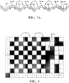
- the floats 234, loops 236 and respective fastener patches P" formed thereby are formed to extend immediately adjacent one another in succession along a full length of the wall 216, with the immediately adjacent patches P" being divided from one another by a weft filament 214 ( Figure 3A ).
- the user can fix the entirety of the length of the sleeve 210 to the support member 32 without concern of axially aligning patches P" of the sleeve 110 with the support member 32, thereby simplifying attachment of the sleeve 210 to the support member 32.
- the floats 34, 134, 234 forming the patches P, P', P" can be formed with corresponding weft filaments 14, 114, 214 ( Figures 7 and 8 ), if desired, as will be understood by a person possessing ordinary skill in the art upon viewing the disclosure herein.
- At least some of the warp filaments 12, 112, 212 can be provided as monofilaments and/or less bulky multifilaments, as compared to the bulky, fluffy multifilaments 33 forming the loops 36, 136, 236. Accordingly, a vast majority of the sleeve wall 16, 116, 216 can be formed as desired for the intended application, with a relatively small portion of the wall 16, 116, 216 being formed having a patch P, P', P" of loops 36, 136, 236, if desired.
- a sleeve 310 is shown in accordance with another non-limiting embodiment of the disclosure, wherein the same reference numerals as used above, offset by a factor of 300, are used to identify like features.
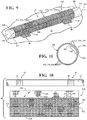
- the floats 334, loops 336 and respective fastener patch P''' formed thereby is shown formed to extend about the entirety or substantially entirety (meaning it could be slightly less than the entirety) of the outwardly exposed surface of the sleeve 310 from one end 324 to an opposite end 326.
- an overlapped region is formed by the regions of the wall 316 extending from the opposite sides 318, 320 being brought into overlapped relation with one another, wherein, as best shown in Figures 10 and 11 , the overlapped region OR immediately adjacent and extending from the underlying side 318 does not include the bulky, fluffy yarn 333 forming the floats 334, thereby allowing for a tight overlap, and further providing a visual indicator for the desired amount of overlap of the opposite sides 318, 320. Further yet, by not having to include the bulky, fluffy yarn 333 in the overlapped region OR, the cost of the sleeve 310 is reduced by not having to include potentially more expensive bulky, fluffy yarns 333 over the entirety of the wall 316.
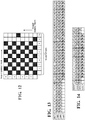
- a weave diagram is illustrated in accordance with one aspect of the disclosure, wherein the weave diagram shows ends of warp filaments 312 along the horizontal axis numbered 1-10, with the warp filaments 312 extending along columns 1-10 in a vertical warp direction.
- the warp filaments 312 are identified by white spaces passing over corresponding weft filaments 314, while the weft filaments 314 are identified by black spaces passing over corresponding warp filaments 312.
- the vertically extending warp filaments 312 in columns 1-8 are woven with the corresponding horizontally extending weft filaments 314 in a plain weave pattern, by way of example and without limitation, while the vertically extending fluffy, bulky warp multifilaments 333 in columns 9-10 are woven with the corresponding horizontally extending weft filaments 314 in a pattern sufficient to form floats 334, shown, by way of example and without limitation, as a satin weave pattern.
- the weave pattern of Figure 12 in accordance with one aspect of the disclosure, is followed using the warp filaments 312, 333 identified in the warp end diagram of Figure 13 .
- 38 dents are used to construct the non-limiting sleeve, such as the sleeve of Figure 9 , having a diameter of about 13mm, by way of example and without limitation.
- Each of the 38 dents are woven with one or a plurality of warp end filaments, with the warp dents 1-11, corresponding to the overlap region (OR) extending from the underlying side 318, being woven solely with 2 warp end filaments 312 per dent, and in one embodiment, the 2 warp end filaments 312, identified by white circles (o), being provided in a non-limiting embodiment as standard multifilaments having a linear mass between about 133-147 tex.
- each of the remaining warp dents 12-38 corresponding to the non-overlap region, extending from the overlap region (OR) to the overlying side 320, being woven with the same 2 warp end filaments 312 and in addition with a single bulky, fluffy multifilament 333, identified by black circles ( ⁇ ), being provided in a non-limiting embodiment as multifilaments having a linear mass of about 230tex +/- 20tex.
- each of the dents 1-38 include a plurality of warp filaments 312, with some of the dents further including bulky, fluffy multifilaments 333.
- the bulky, fluffy multifilaments 333 are woven via the weave pattern shown in columns 9 and 10 of Figure 12 , and thus, the satin loops 336 of the bulky, fluffy multifilaments 333 in adjacent dents are formed in staggered relation relative to one another, thereby avoiding the formation of open spaces or gaps free of loops 336, thereby enhancing the coverage of the outer surface with loops 336, and thus, maximizing the ability of the entirety of the outer surface of the sleeve 310 to be fixed to corresponding hooks 38 of a hook portion 40 of a standard hook-and-loop type fastener.
- each filament within each dent 1-38 is identified as being woven in one of the patterns associated with columns 1-10 of Figure 12 by a corresponding number 1-10 beneath the corresponding symbol (o), ( ⁇ ), as will be understood by one skilled in the art.
- the bulky, fluffy multifilaments 333 being formed of very light and lofty multifilaments, such as can be purchased under specification polyethylene terephthalate (PET) 12 x 167 FR, by way of example and without limitation, numerous small, fluffy loops 336 are provided for fixation to hooks 38 of a hook portion 40 of a standard hook-and-loop type fastener, as discussed above. Accordingly, it is to be recognized that the aforementioned bulky, fluffy multifilament 333 can be used in any of the embodiments discussed above.
- the weft filaments 314 can be provided of monofilaments and/or multifilaments, as discussed above, and in one presently preferred embodiment, at least in part or in entirety of heat-settable filaments, such as from heat-settable polyester monofilaments having a diameter between about 0.18-0.26mm, and more preferably between about 0.20-0.24mm, by way of example and without limitation.
- the heat-settable weft filaments 314 are able to be heat-set at a temperature that avoids flattening the fluffiness of the loops 336 of the bulky, fluffy multifilaments 333, and in accordance with one aspect, the wall 316 is able to be heat-set at about 205°C +/- 5°C as a rate of about 3.75m/min, whereupon the wall 316 retains the tubular heat-set configuration as shown in Figures 9 and 11 .
- Each of the warp and weft filaments 312, 314, 333 can be provided having fire retardant properties, with a limit oxygen index (LOI, wherein LOI is the minimum concentration of oxygen, expressed as a percentage, that will support combustion of a polymer) greater than 25%, thereby rendering the sleeve 310 suitable for use in elevated temperature environments.
- LOI limit oxygen index
- the warp and weft filaments discussed above for each of the aforementioned embodiments may also be provided having fire retardant properties.
- the filaments used to construct the aforementioned sleeves can be provided as halogen-free filaments.
- a sleeve having a larger or smaller diameter than the 13mm diameter sleeve discussed above can be made using similar patterns discussed above, with more or fewer warp filaments.
- a sleeve having a diameter of about 5mm is contemplated herein, wherein the sleeve can be made having about 19 warp dents, wherein 15 of the warp dents are each formed including 3 warp ends, including 2 warp filaments 312 and 1 fluffy, bulky warp multifilament 333, with the 2 warp filaments 312 being woven in a plain weave with corresponding weft filaments 314, and the bulky warp multifilament 333 being woven to form outwardly facing floats, such as in a satin pattern.
- the remaining 4 dents can each be formed including 2 warp filaments 312, with 2 of the 4 dents extending immediately adjacent opposite lengthwise extending sides configured for overlapping relation with one another.
- Such an example is shown in Figure 14 .
- the associated weft yarns can be provided as discussed above, such as from heat-settable filaments.
Landscapes
- Engineering & Computer Science (AREA)
- Textile Engineering (AREA)
- Architecture (AREA)
- Civil Engineering (AREA)
- Structural Engineering (AREA)
- Woven Fabrics (AREA)
Description
- This patent claims the benefit of
U.S. Provisional Application Serial No. 62/453,143, filed February 1, 2017 15/885,638, filed January 31, 2018 - This invention relates generally to textile sleeves for protecting elongate members, and more particularly to textile sleeves configured for attachment to support member.
- Wires are commonly bundled together and protected by textile sleeves in the form of a wire harness. The wire harness is often fixed to an external support member, such as a vehicle frame member or some other vehicle component to maintain the wire harness in a fixed location. Typically, supplemental members, separate from the wire harness, are used to fix the wire harness in location, such as clips, adhesives, plastic ties, and separately provided hook and loop fasteners, wherein one of the hook or loop portions is fixed via a secondary operation, such as via stitching or adhesive, to an external surface of the sleeve for fixation to the other of the hook or loop that is fixed to the desired support member. Although these mechanisms can prove useful for fixing the wire harness in location, they come at a cost associated with the secondary products and operations. Document
US 5300337 A describes an example of tubes with closure means comprising multifilament, bulky yarn interlaced in a sleeving material and relatively unconfined along one of its marginal edges and of Velcro® brand hook tape or similar hook type elements disposed along the other marginal edge. - A sleeve constructed in accordance with the disclosure herein overcomes at least the drawbacks discussed above.
- A wrappable textile sleeve for protecting an elongate member includes a plurality of warp filaments and at least one weft filament woven with one another to form a woven wall. The woven wall has opposite sides extending lengthwise between opposite ends. The opposite sides are wrappable about a central longitudinal axis into overlapping relation with one another to bound the elongate member within a cavity of the sleeve. To allow the woven wall to be readily fixed to a support member, at least one warp and/or weft filament is provided as a bulky, fluffy multifilament, wherein the bulky, fluffy multifilament is woven to form at least one float extending over 2 or more weft and/or warp yarns, wherein the at least one float provides loops sufficient to readily fix themselves to hooks of a standard hook and loop fastener.
- In accordance with a further aspect of the invention, a plurality of the warp filaments are provided as a bulky, fluffy multifilaments adjacent one another, with the adjacent bulky, fluffy multifilaments forming floats adjacent one another.
- In accordance with a further aspect of the invention, a plurality of the weft filaments are provided as a bulky, fluffy multifilaments adjacent one another, with the adjacent bulky, fluffy multifilaments forming floats adjacent one another.
- In accordance with a further aspect of the invention, the floats can be formed having a twill pattern.
- In accordance with a further aspect of the invention, the floats can be formed having a satin pattern.
- In accordance with a further aspect of the invention, the floats can be formed to extend over only a portion of the length of the wall.
- In accordance with a further aspect of the invention, the floats can be formed to extend over only a portion of the circumference of the wall.
- In accordance with a further aspect of the invention, the floats can be formed to extend over a full length of the wall.
- In accordance with a further aspect of the invention, the floats can be formed to extend over a full circumference of the wall.
- In accordance with a further aspect of the invention, at least some of the warp filaments can be provided as monofilaments.
- In accordance with a further aspect of the invention, at least some of the weft filaments can be provided as heat-settable monofilaments to be heat-set and bias the opposite sides into overlapping relation with one another to facilitate assembly of the sleeve about the elongate member.
- In accordance with a further aspect of the invention, the warp filaments are woven over a plurality of dents, wherein a plurality of the dents each include a plurality of filaments, with at least one of the plurality of filaments including a bulky, fluffy multifilament.
- In accordance with a further aspect of the invention, at least one of the plurality of filaments in each of the plurality of dents is a standard multifilament having a denier greater than the denier of the bulky, fluffy multifilament.
- In accordance with a further aspect of the invention, the bulky, fluffy multifilament can be woven in a satin weave pattern and the standard multifilament within the same dent as the bulky, fluffy multifilament can be woven in a plain weave pattern.
- In accordance with a further aspect of the invention, the denier of the bulky, fluffy multifilament is between about 210-250tex.
- In accordance with a further aspect of the invention, the denier of the standard multifilament is about 1400Dtex.
- In accordance with a further aspect of the invention, a method of constructing a wrappable textile sleeve for protecting an elongate member includes weaving a plurality of warp filaments and at least one weft filament with one another to form a woven wall. The method further includes weaving the wall having opposite sides extending lengthwise between opposite ends, with the opposite sides being wrappable about a central longitudinal axis into overlapping relation with one another to bound the elongate member within a cavity of the sleeve. To allow the woven wall to be readily fixed to a support member, the method further includes weaving at least one warp and/or weft filament as a bulky, fluffy multifilament, and weaving the bulky, fluffy multifilament to form at least one float extending over 2 or more weft and/or warp yarns, with the at least one float providing loops sufficient to readily fix themselves to hooks of a standard hook and loop fastener.
- In accordance with a further aspect of the invention, the method can further include weaving a plurality of the warp filaments as bulky, fluffy multifilaments adjacent one another, and weaving the adjacent bulky, fluffy multifilaments having floats adjacent one another to provide an increased surface area of loops configured to interlock with hooks as a hook-and-loop type fastener.
- In accordance with a further aspect of the invention, the method can further include weaving a plurality of the weft filaments as bulky, fluffy multifilaments adjacent one another, and weaving the adjacent bulky, fluffy multifilaments forming floats adjacent one another.
- In accordance with a further aspect of the invention, the method can further include weaving the floats in a twill pattern.
- In accordance with a further aspect of the invention, the method can further include weaving the floats having a satin pattern.
- In accordance with a further aspect of the invention, the method can further include weaving the floats to extend over only a portion of the length of the wall.
- In accordance with a further aspect of the invention, the method can further include weaving the floats to extend over only a portion of the circumference of the wall.
- In accordance with a further aspect of the invention, the method can further include weaving the floats to extend over a full length of the wall.
- In accordance with a further aspect of the invention, the method can further include weaving the floats to extend over a full circumference of the wall.
- In accordance with a further aspect of the invention, the method can further include weaving at least some of the warp filaments as monofilaments to enhance the abrasion resistance of the sleeve.
- In accordance with a further aspect of the invention, the method can further include heat-setting at least some of the weft filaments to bias the opposite sides into overlapping relation with one another.
- In accordance with a further aspect of the invention, the method can further include weaving the warp filaments over a plurality of dents and providing a plurality of the dents each including a plurality of filaments, with at least one of the plurality of filaments within at least some of the dents including the bulky, fluffy multifilament.
- In accordance with a further aspect of the invention, the method can further include providing at least one of the plurality of filaments within each of the dents as a standard multifilament having a denier greater than the denier of the bulky, fluffy multifilament.
- In accordance with a further aspect of the invention, the method can further include weaving the bulky, fluffy multifilament in a satin weave pattern and weaving the standard multifilament in a plain weave pattern within the same dent.
- In accordance with a further aspect of the invention, the method can further include providing the denier of the bulky, fluffy multifilament being between about 210-250tex.
- In accordance with a further aspect of the invention, the method can further include providing the denier of the standard multifilament being about 140tex +/-5%.
- These and other features and advantages will become readily apparent to those skilled in the art in view of the following detailed description of the presently preferred embodiments and best mode, appended claims, and accompanying drawings, in which:
-
Figure 1 is a schematic perspective view of a wrappable protective textile sleeve constructed in accordance with one aspect of the disclosure shown wrapped about an elongate member to be protected and attached to a support member; -
Figure 1A is a schematic plan view of a wrappable protective textile sleeve constructed in accordance with one aspect of the disclosure for attachment to a support member, with the sleeve shown in an unwrapped state; -
Figure 2 is a schematic plan view of a wrappable protective textile sleeve constructed in accordance with another aspect of the disclosure for attachment to a support member, with the sleeve shown in an unwrapped state; -
Figure 3 is a schematic plan view of a wrappable protective textile sleeve constructed in accordance with yet another aspect of the disclosure for attachment to a support member, with the sleeve shown in an unwrapped state; -
Figure 4 is a weave diagram used to construct a sleeve in accordance with one aspect of the disclosure; -
Figure 5 is a fragmentary schematic end view of a wall of a wrappable protective textile sleeve constructed in accordance with one aspect of the disclosure; -
Figure 6 is a fragmentary schematic end view of a wall of a wrappable protective textile sleeve constructed in accordance with another aspect of the disclosure; -
Figure 7 is a fragmentary schematic end view of a wall of a wrappable protective textile sleeve constructed in accordance with yet another aspect of the disclosure; -
Figure 8 is a fragmentary schematic end view of a wall of a wrappable protective textile sleeve constructed in accordance with yet a further aspect of the disclosure; -
Figure 9 is a schematic perspective view of a wrappable protective textile sleeve constructed in accordance with one aspect of the disclosure shown wrapped about an elongate member to be protected and attached to a support member; -
Figure 10 is a schematic plan view of the wrappable protective textile sleeve ofFigure 9 shown in an unwrapped state; -
Figure 11 is a schematic cross-sectional view of the wrappable protective textile sleeve ofFigure 9 ; -
Figure 12 is a weave diagram used to construct the wrappable protective textile sleeve ofFigure 9 ; -
Figure 13 is a diagram illustrating the type of warp end filaments used to construct a wrappable protective textile sleeve in accordance with one aspect of the disclosure, such as via the weave diagram ofFigure 12 ; and -
Figure 14 is a view similar toFigure 13 used to construct a wrappable protective textile sleeve in accordance with another aspect of the disclosure. - Referring in more detail to the drawings,
Figures 1 and 1A show schematically a wrappable, protective sleeve, referred to hereafter simply assleeve 10, constructed in accordance with one presently preferred, non-limiting embodiment of the disclosure, wherein, as shown inFigure 1 , thewall 16 is constructed to be releasably fixed to asupport member 32. Thesleeve 10 includes a plurality of warp yarns, also referred to aswarp filaments 12, and at least one or a plurality of weft yarns, also referred to asweft filaments 14, woven with one another to form a woven substrate, also referred to simply aswall 16. Thewall 16 hasopposite sides longitudinal axis 22 into overlapping relation with one another to bound anelongate member 28 to be protected within a circumferentially enclosedcavity 30 of thesleeve 10, with theopposite sides longitudinal axis 22 between opposite open ends 24, 26. To provide an ability for thesleeve 10 to be readily fixed to thesupport member 32, at least one warp and/orweft filament Figures 1 and 1A as being a plurality ofwarp filaments 12, is provided as a bulky,fluffy multifilament 33, wherein each bulky,fluffy multifilament 33 is woven to form at least onefloat 34 extending over 2 (Figure 5 ) or more (Figure 6 ) weft and/orwarp yarns float 34 providesloops 36 sufficient to readily fix themselves tohooks 38 of ahook portion 40 of a standard hook and loop fastener, such as sometimes purchased under the name Velcro®. Accordingly, thesleeve 10 is able to be releasably fixed to thesupport member 32 without need of having to fix a separate loop fastener portion to thewall 16, as theloops 36 integrally woven into thewall 16 of thesleeve 10 already form a loop fastener portion, also referred to as fastener patch P, integral to thesleeve 10 as woven. - In accordance with a further aspect of the disclosure, the
sleeve 10 can be constructed as a self-wrapping sleeve, such that thewall 16 is automatically biased to curl about the centrallongitudinal axis 22 to bring theopposite sides wall 16 of thesleeve 10 via heat-setting at least oneweft filament 14 or a plurality ofweft filaments 14. Accordingly, at least one or a plurality of theweft filaments 14 can be provided as a heat-settable polymeric filament or filaments, wherein the heat-settable weft filament orfilaments 14, whether some of all, are preferably monofilaments of a heat-settable thermoplastic, such as, by way of example and without limitation, polyester, thereby allowing thesleeve 10 to be heat-set or otherwise biased into a tubular form. - In accordance with one non-limiting embodiment shown in
Figures 1 and 1A , a plurality of thewarp filaments 12 are provided as bulky,fluffy multifilaments 33. The plurality ofwarp multifilaments 33 can be woven in immediately adjacent, contiguous relation one another withfloats 34 also being formed adjacent and contiguous one another, such that thefloats 34 are aligned with one another along a circumferential direction. As such, an increased size fastener patch P of theloops 36, in comparison to that as would be formed by s single bulky,fluffy multifilament 33, is formed for attachment to thehook portion 40. As noted, the warp floats 34 extend over a plurality of adjacent weft filaments, and in accordance one aspect of the invention, thefloats 34 can be formed having a twill pattern (Figure 5 ) or satin pattern (Figure 6 ), wherein, as will be understood by a skilled artisan of the textile arts, the satin pattern would form a longer lengthwise extending fastener patch P ofloops 36 than a twill pattern. Of course, it is to be recognized that the respective patches P can be formed in immediate succession with one another to form increased size patches P. The warp floats 34 and fastener patch(es) P formed thereby can be formed to extend over only a portion of the length of thewall 16, in the select, desired location of thewall 16 to be attached to thesupport member 32, or as shown and discussed hereafter, the patch P can be formed in immediately adjacent relation with one another to extend over a full length of thewall 14, depending on the application and the size and location of thehook portion 40 to which theloops 36 will be attached. - In the embodiment of
Figures 1 and 1A , a pair of fastener patches P is formed in over select regions of thewall 16 in predetermined axially spaced relation from one another, and in axial, lengthwise alignment with one another, such that the fastener patches P are automatically located for alignment with and releasable fixation to a pair or more of similarly spaced, correspondinghook portions 40. It is to be recognized that although a pair of the fastener patches P are shown, any desired number of fastener patches P could be formed along the length of thesleeve 10. The fastener patches P are shown as being formed as discrete islands spaced from one another in lengthwise alignment with one another and spaced from theopposite sides wall 16 can be woven via any desired weave pattern, such as a plain weave pattern or otherwise, as desired. Further, it is to be recognized that any type of non-fluffy warp yarn, including monofilament and/or multifilament, can be used in the regions not including the fastener patches P, and thus, the physical properties of thewall 16 on opposite sides of the fastener patches P can be provided as desired, depending on the type ofwarp 12 andweft yarns 14 used. - In
Figure 2 , asleeve 110 is shown in accordance with another non-limiting embodiment of the disclosure, wherein the same reference numerals as used above, offset by a factor of 100, are used to identify like features. Unlike thesleeve 10 ofFigures 1 and 1A , the floats 134, loops 136 and respective fastener patches P' formed thereby are formed to extend from oneside 118 to anopposite side 120, such that upon wrapping thesides wall 116 of thesleeve 110. As such, the user can fix thesleeve 110 to thesupport member 32 without concern of circumferential orientation of thesleeve 110 to thesupport member 32, thereby simplifying attachment of thesleeve 110 to thesupport member 32. Further, this also allows the user to orient a seam 42 (shown inFigure 1 for convenience) extending between the overlappedsides support member 32, if desired, thereby acting to shield theseam 42 against being inadvertently opened from the ingress of contamination therethrough. It is to be recognized that although a pair of the fastener patches P are shown in axially spaced relation from one another, any desired number of fastener patches P could be formed along the length of thesleeve 110. It is further to be recognized that in the region(s) of thewall 116 not including the fastener patches P, any desired weave pattern can be used to interlace the warp andweft filaments - In
Figure 3 , asleeve 210 is shown in accordance with another non-limiting embodiment of the disclosure, wherein the same reference numerals as used above, offset by a factor of 200, are used to identify like features. Unlike thesleeve 10 ofFigures 1 and 1A , the floats 234, loops 236 and respective fastener patches P" formed thereby are formed to extend immediately adjacent one another in succession along a full length of thewall 216, with the immediately adjacent patches P" being divided from one another by a weft filament 214 (Figure 3A ). As such, the user can fix the entirety of the length of thesleeve 210 to thesupport member 32 without concern of axially aligning patches P" of thesleeve 110 with thesupport member 32, thereby simplifying attachment of thesleeve 210 to thesupport member 32. - In accordance with another aspect of the disclosure, in each of the embodiments discussed above, rather than weaving the
floats 34, 134, 234 forming the patches P, P', P" withcorresponding warp filaments floats 34, 134, 234 forming the patches P, P', P" can be formed withcorresponding weft filaments Figures 7 and 8 ), if desired, as will be understood by a person possessing ordinary skill in the art upon viewing the disclosure herein. - In accordance with a further aspect of the disclosure, at least some of the
warp filaments fluffy multifilaments 33 forming theloops 36, 136, 236. Accordingly, a vast majority of thesleeve wall wall loops 36, 136, 236, if desired. - In
Figure 9 , asleeve 310 is shown in accordance with another non-limiting embodiment of the disclosure, wherein the same reference numerals as used above, offset by a factor of 300, are used to identify like features. Unlike thesleeve 10 ofFigures 1 and 1A , the floats 334, loops 336 and respective fastener patch P''' formed thereby is shown formed to extend about the entirety or substantially entirety (meaning it could be slightly less than the entirety) of the outwardly exposed surface of thesleeve 310 from oneend 324 to anopposite end 326. With thesleeve 310 being wrappable about a centrallongitudinal axis 322, an overlapped region (OR) is formed by the regions of thewall 316 extending from theopposite sides Figures 10 and 11 , the overlapped region OR immediately adjacent and extending from theunderlying side 318 does not include the bulky, fluffy yarn 333 forming the floats 334, thereby allowing for a tight overlap, and further providing a visual indicator for the desired amount of overlap of theopposite sides sleeve 310 is reduced by not having to include potentially more expensive bulky, fluffy yarns 333 over the entirety of thewall 316. - In
Figure 12 , a weave diagram is illustrated in accordance with one aspect of the disclosure, wherein the weave diagram shows ends ofwarp filaments 312 along the horizontal axis numbered 1-10, with thewarp filaments 312 extending along columns 1-10 in a vertical warp direction. In the diagram, thewarp filaments 312 are identified by white spaces passing overcorresponding weft filaments 314, while theweft filaments 314 are identified by black spaces passing overcorresponding warp filaments 312. Accordingly, the vertically extendingwarp filaments 312 in columns 1-8 are woven with the corresponding horizontally extendingweft filaments 314 in a plain weave pattern, by way of example and without limitation, while the vertically extending fluffy, bulky warp multifilaments 333 in columns 9-10 are woven with the corresponding horizontally extendingweft filaments 314 in a pattern sufficient to form floats 334, shown, by way of example and without limitation, as a satin weave pattern. The weave pattern ofFigure 12 , in accordance with one aspect of the disclosure, is followed using thewarp filaments 312, 333 identified in the warp end diagram ofFigure 13 . InFigure 13 , 38 dents are used to construct the non-limiting sleeve, such as the sleeve ofFigure 9 , having a diameter of about 13mm, by way of example and without limitation. Each of the 38 dents are woven with one or a plurality of warp end filaments, with the warp dents 1-11, corresponding to the overlap region (OR) extending from theunderlying side 318, being woven solely with 2warp end filaments 312 per dent, and in one embodiment, the 2warp end filaments 312, identified by white circles (o), being provided in a non-limiting embodiment as standard multifilaments having a linear mass between about 133-147 tex. In contrast, each of the remaining warp dents 12-38, corresponding to the non-overlap region, extending from the overlap region (OR) to theoverlying side 320, being woven with the same 2warp end filaments 312 and in addition with a single bulky, fluffy multifilament 333, identified by black circles (●), being provided in a non-limiting embodiment as multifilaments having a linear mass of about 230tex +/- 20tex. Accordingly, each of the dents 1-38 include a plurality ofwarp filaments 312, with some of the dents further including bulky, fluffy multifilaments 333. The bulky, fluffy multifilaments 333 are woven via the weave pattern shown incolumns Figure 12 , and thus, the satin loops 336 of the bulky, fluffy multifilaments 333 in adjacent dents are formed in staggered relation relative to one another, thereby avoiding the formation of open spaces or gaps free of loops 336, thereby enhancing the coverage of the outer surface with loops 336, and thus, maximizing the ability of the entirety of the outer surface of thesleeve 310 to be fixed tocorresponding hooks 38 of ahook portion 40 of a standard hook-and-loop type fastener. In the chart ofFigure 13 , each filament within each dent 1-38 is identified as being woven in one of the patterns associated with columns 1-10 ofFigure 12 by a corresponding number 1-10 beneath the corresponding symbol (o), (●), as will be understood by one skilled in the art. As discussed above in the previous embodiments, with the bulky, fluffy multifilaments 333 being formed of very light and lofty multifilaments, such as can be purchased under specification polyethylene terephthalate (PET) 12 x 167 FR, by way of example and without limitation, numerous small, fluffy loops 336 are provided for fixation to hooks 38 of ahook portion 40 of a standard hook-and-loop type fastener, as discussed above. Accordingly, it is to be recognized that the aforementioned bulky, fluffy multifilament 333 can be used in any of the embodiments discussed above. - The
weft filaments 314 can be provided of monofilaments and/or multifilaments, as discussed above, and in one presently preferred embodiment, at least in part or in entirety of heat-settable filaments, such as from heat-settable polyester monofilaments having a diameter between about 0.18-0.26mm, and more preferably between about 0.20-0.24mm, by way of example and without limitation. The heat-settable weft filaments 314 are able to be heat-set at a temperature that avoids flattening the fluffiness of the loops 336 of the bulky, fluffy multifilaments 333, and in accordance with one aspect, thewall 316 is able to be heat-set at about 205°C +/- 5°C as a rate of about 3.75m/min, whereupon thewall 316 retains the tubular heat-set configuration as shown inFigures 9 and 11 . - Each of the warp and
weft filaments sleeve 310 suitable for use in elevated temperature environments. It is to be recognized that the warp and weft filaments discussed above for each of the aforementioned embodiments may also be provided having fire retardant properties. It is further contemplate herein that the filaments used to construct the aforementioned sleeves can be provided as halogen-free filaments. - It is contemplated herein that a sleeve having a larger or smaller diameter than the 13mm diameter sleeve discussed above can be made using similar patterns discussed above, with more or fewer warp filaments. For example, a sleeve having a diameter of about 5mm is contemplated herein, wherein the sleeve can be made having about 19 warp dents, wherein 15 of the warp dents are each formed including 3 warp ends, including 2
warp filaments warp filaments 312 being woven in a plain weave withcorresponding weft filaments 314, and the bulky warp multifilament 333 being woven to form outwardly facing floats, such as in a satin pattern. Meanwhile, the remaining 4 dents can each be formed including 2warp filaments 312, with 2 of the 4 dents extending immediately adjacent opposite lengthwise extending sides configured for overlapping relation with one another. Such an example is shown inFigure 14 . It is to be recognized that the associated weft yarns can be provided as discussed above, such as from heat-settable filaments.
Claims (15)
- A wrappable textile sleeve (10; 110; 210; 310) for protecting elongate members (28), comprising:a wall (16; 116; 216; 316) including a plurality of warp filaments (12; 112; 212; 312) and at least one weft filament (14; 114; 214; 314) woven with one another, said wall having opposite sides (18, 20; 118, 120; 318, 320) extending lengthwise in generally parallel relation with a central longitudinal axis (22; 322) between opposite ends (24, 26; 324, 326), said opposite sides being wrappable about said central longitudinal axis into overlapping relation with one another to bound the elongate member within a cavity (30; 330) of the sleeve; andat least one of said warp and/or weft filament being provided as a bulky, fluffy multifilament (33; 333)characterised in that the bulky, fluffy multifilament is woven to form at least one float (34; 134; 234; 334) extending over 2 or more weft and/or warp yarns, wherein said at least one float provides loops (36; 136; 236; 336) suited for attachment to hooks (38) of a standard hook and loop fastener.
- The wrappable textile sleeve (10; 110; 210; 310) of claim 1, further including a plurality of said warp filaments (12; 112; 212; 312) being provided as said bulky, fluffy multifilaments (33; 333) adjacent one another, with said adjacent bulky, fluffy multifilaments having floats adjacent one another to form a discrete fastener patch (P; P'; P"; P''') of said loops (36; 136; 236; 336).
- The wrappable textile sleeve (10; 110; 210; 310) of claim 1, further including a plurality of said weft filaments (14; 114; 214; 314) being provided as said bulky, fluffy multifilaments (33; 333) adjacent one another, with said adjacent bulky, fluffy multifilaments forming floats adjacent one another to form a discrete fastener patch (P; P'; P"; P''') of said loops (36; 136; 236; 336).
- The wrappable textile sleeve (10; 110; 210; 310) of claim 1, wherein said at least one float (34; 134; 234; 334) is formed having a twill pattern or wherein said at least one float is formed having a satin pattern.
- The wrappable textile sleeve (10; 110; 210; 310) of claim 1, wherein said at least one float (34; 134) is formed to extend over only a portion of the length of the wall or wherein a plurality of said at least one floats (234; 334) extend in succession along a full length of the wall.
- The wrappable textile sleeve (10; 110; 210; 310) of claim 2, wherein said floats (34; 234) can be formed to extend over only a portion of the circumference of said wall (16; 216) or wherein said at floats (134; 334) can be formed to extend about the full circumference of said wall (116; 316) or wherein at least some of said warp filaments (12; 112; 212; 312) are provided as monofilaments.
- The wrappable textile sleeve (10; 110; 210; 310) of claim 1, wherein at least some of said weft filaments (14; 114; 214; 314) are provided as heat-settable monofilaments to be heat-set and bias said opposite sides (18, 20; 118, 120; 318, 320) into overlapping relation with one another and optionally wherein each of said weft filaments are provided as heat-settable monofilaments to be heat-set and bias said opposite sides into overlapping relation with one another.
- The wrappable textile sleeve (10; 110; 210; 310) of claim 1, wherein said warp filaments (12; 112; 212; 312) are woven over a plurality of dents, wherein a plurality of said dents each include a plurality of filaments, with at least one of said plurality of filaments including said bulky, fluffy multifilament (33; 333).
- A method of constructing a wrappable textile sleeve (10; 110; 210; 310) for protecting an elongate member (28), comprising:weaving a plurality of warp filaments (12; 112; 212; 312) and at least one weft filament (14; 114; 214; 314) with one another to form a woven wall (16; 116; 216; 316);weaving the wall having opposite sides (18, 20; 118, 120; 318, 320) extending lengthwise between opposite ends (24, 26; 324, 326), with the opposite sides being wrappable about a central longitudinal axis (22; 322) into overlapping relation with one another; andweaving at least one warp and/or weft filament as a bulky, fluffy multifilament (33; 333); andcharacterised by forming at least one float (34; 134; 234; 334) extending over 2 or more weft and/or warp yarns with the fluffy multifilament, with the at least one float forming a plurality of loops (36; 136; 236; 336) configured for fixation to hooks (38) of a standard hook and loop fastener.
- The method of claim 9, further including weaving a plurality of the warp filaments (12; 112; 212; 312) as the bulky, fluffy multifilaments (33; 333) adjacent one another so that adjacent bulky, fluffy multifilaments form floats (34; 134; 234; 334) adjacent one another to form at least one discrete fastener patch (P; P'; P"; P''') of the loops (36; 136; 236; 336).
- The method of claim 9, further including weaving a plurality of the weft filaments as the bulky, fluffy multifilaments adjacent one another so that adjacent bulky, fluffy multifilaments form floats adjacent one another to form at least one discrete fastener patch of the loops.
- The method of claim 10 or 11, further including forming the at least one discrete patch (P; P') to extend over only a portion of the length of the wall (16; 116).
- The method of claim 12, further including forming a plurality of the discrete patches (P; P'; P") along the length of the wall (16; 116; 216), with the plurality of patches being axially aligned with one another and axially spaced from one another by portions of the wall being free of patches and optionally further including forming the patches to extend over only a portion of a circumference of the wall or about an entirety of a circumference of the wall.
- The method of claim 10, further including forming a plurality of the discrete patches (P") immediately adjacent one another and axially aligned with one another along the entire length of the wall (216).
- The method of claim 11, further including forming a plurality of the discrete patches immediately adjacent one another and circumferentially aligned with one another to extend about an entirety of a circumference of the wall.
Applications Claiming Priority (3)
| Application Number | Priority Date | Filing Date | Title |
|---|---|---|---|
| US201762453143P | 2017-02-01 | 2017-02-01 | |
| US15/885,638 US10538866B2 (en) | 2017-02-01 | 2018-01-31 | Woven sleeve with integral attachment loops and method of construction thereof |
| PCT/US2018/016328 WO2018144656A1 (en) | 2017-02-01 | 2018-02-01 | Woven sleeve with integral attachment loops and method of construction thereof |
Publications (2)
| Publication Number | Publication Date |
|---|---|
| EP3577263A1 EP3577263A1 (en) | 2019-12-11 |
| EP3577263B1 true EP3577263B1 (en) | 2021-03-17 |
Family
ID=63039200
Family Applications (1)
| Application Number | Title | Priority Date | Filing Date |
|---|---|---|---|
| EP18706029.8A Active EP3577263B1 (en) | 2017-02-01 | 2018-02-01 | Woven sleeve with integral attachment loops and method of construction thereof |
Country Status (7)
| Country | Link |
|---|---|
| US (1) | US10538866B2 (en) |
| EP (1) | EP3577263B1 (en) |
| JP (1) | JP7117330B2 (en) |
| KR (1) | KR20190111059A (en) |
| CN (1) | CN110382755B (en) |
| BR (1) | BR112019015813A2 (en) |
| WO (1) | WO2018144656A1 (en) |
Families Citing this family (7)
| Publication number | Priority date | Publication date | Assignee | Title |
|---|---|---|---|---|
| JP6950202B2 (en) * | 2016-04-18 | 2021-10-13 | 株式会社オートネットワーク技術研究所 | Electric wire with exterior member |
| CN114375353B (en) * | 2019-09-10 | 2023-08-11 | 费德罗-莫格尔动力系公司 | Corrugated woven sleeve and method of making same |
| US11643758B2 (en) * | 2020-03-13 | 2023-05-09 | Shenzhen Jdd Tech New Material Co., Ltd. | Protective tube |
| CN113136646B (en) * | 2021-03-01 | 2022-09-09 | 西安理工大学 | A method of personalizing custom protective gear products |
| US12460324B2 (en) | 2023-04-21 | 2025-11-04 | Systems Protection Group Us Llc | Wrappable, woven, abrasion and EMI resistant sleeve |
| WO2024220856A1 (en) * | 2023-04-21 | 2024-10-24 | Federal-Mogul Powertrain Llc | Wrappable, woven, abrasion and emi resistant sleeve |
| WO2025165932A1 (en) * | 2024-01-30 | 2025-08-07 | Federal-Mogul Powertrain Llc | Textile sleeve assembly with ultrasonically welded attachment features and method of construction thereof |
Citations (1)
| Publication number | Priority date | Publication date | Assignee | Title |
|---|---|---|---|---|
| US20140305536A1 (en) * | 2013-03-08 | 2014-10-16 | Federal-Mogul Powertrain, Inc. | Wrappable textile sleeve with extendable electro-functional yarn leads and method of construction thereof |
Family Cites Families (17)
| Publication number | Priority date | Publication date | Assignee | Title |
|---|---|---|---|---|
| US4207885A (en) | 1979-03-07 | 1980-06-17 | Carolon Company | Woven elastic compression bandage |
| US4654246A (en) | 1985-09-05 | 1987-03-31 | Actief, N.V. | Self-engaging separable fastener |
| US4714096A (en) | 1985-12-03 | 1987-12-22 | George C. Moore Co. | Elastic fabric provided with a looped gripping surface |
| US5178923A (en) | 1992-01-09 | 1993-01-12 | Textilver S.A. | Wraparound closure device |
| US5300337A (en) | 1992-01-09 | 1994-04-05 | The Bentley-Harris Manufacturing Company | Wraparound closure device |
| US6443187B1 (en) | 1998-03-30 | 2002-09-03 | Velcro Industries B.V. | Aligning woven loop elements to form mounting sleeves |
| US5996189A (en) | 1998-03-30 | 1999-12-07 | Velcro Industries B.V. | Woven fastener product |
| JP2000209753A (en) | 1999-01-12 | 2000-07-28 | Kuraray Living Kk | Linear body fixing structure and linear body |
| US6328080B1 (en) | 2000-09-27 | 2001-12-11 | Federal-Mogul Systems Protection Group, Inc. | Woven sleeve with integral monofilament fasteners |
| TW200624617A (en) | 2004-07-20 | 2006-07-16 | Federal Mogul World Wide Inc | Self-curling sleeve |
| CN101052760A (en) * | 2004-07-20 | 2007-10-10 | 费德罗-莫格尔全球有限公司 | Self-curling sleeve |
| US7426840B2 (en) | 2007-01-04 | 2008-09-23 | Sytz Ronald M | Spacer fabric with integral, exposed loops and method of making |
| US8701716B2 (en) * | 2008-02-29 | 2014-04-22 | Federal-Mogul Corporation | Protective textile sleeve having high edge abrasion resistance and method of construction |
| CA2778167C (en) | 2009-11-25 | 2017-07-04 | Federal-Mogul Powertrain, Inc. | Wrappable textile sleeve with integral attachment and closure device |
| US8468853B2 (en) | 2011-02-07 | 2013-06-25 | Southern Weaving Company | Knitted velcro sleeve |
| US9913415B2 (en) * | 2013-03-13 | 2018-03-06 | Federal-Mogul Powertrain Llc | EMI shielding textile fabric, wrappable sleeve constructed therefrom and method of construction thereof |
| CN107815778A (en) | 2016-09-14 | 2018-03-20 | 周朝木 | Self-body adhesive button fabric |
-
2018
- 2018-01-31 US US15/885,638 patent/US10538866B2/en active Active
- 2018-02-01 BR BR112019015813-8A patent/BR112019015813A2/en not_active Application Discontinuation
- 2018-02-01 CN CN201880014792.4A patent/CN110382755B/en active Active
- 2018-02-01 KR KR1020197023615A patent/KR20190111059A/en not_active Withdrawn
- 2018-02-01 EP EP18706029.8A patent/EP3577263B1/en active Active
- 2018-02-01 JP JP2019562242A patent/JP7117330B2/en active Active
- 2018-02-01 WO PCT/US2018/016328 patent/WO2018144656A1/en not_active Ceased
Patent Citations (1)
| Publication number | Priority date | Publication date | Assignee | Title |
|---|---|---|---|---|
| US20140305536A1 (en) * | 2013-03-08 | 2014-10-16 | Federal-Mogul Powertrain, Inc. | Wrappable textile sleeve with extendable electro-functional yarn leads and method of construction thereof |
Also Published As
| Publication number | Publication date |
|---|---|
| EP3577263A1 (en) | 2019-12-11 |
| JP7117330B2 (en) | 2022-08-12 |
| CN110382755A (en) | 2019-10-25 |
| JP2020506308A (en) | 2020-02-27 |
| BR112019015813A2 (en) | 2020-03-31 |
| KR20190111059A (en) | 2019-10-01 |
| CN110382755B (en) | 2021-08-20 |
| WO2018144656A1 (en) | 2018-08-09 |
| US10538866B2 (en) | 2020-01-21 |
| US20180223457A1 (en) | 2018-08-09 |
Similar Documents
| Publication | Publication Date | Title |
|---|---|---|
| US10538866B2 (en) | Woven sleeve with integral attachment loops and method of construction thereof | |
| EP0620873B1 (en) | Wraparound closure device | |
| US5178923A (en) | Wraparound closure device | |
| EP1334302B1 (en) | Sleeve with integral fasteners | |
| US9091002B2 (en) | Wrappable end fray resistant protective textile sleeve and method of construction thereof | |
| KR101386005B1 (en) | Self-curling knitted sleeve and method of fabrication | |
| EP1994210B1 (en) | Low profile textile wire bundler sleeve | |
| US9228278B2 (en) | Protective textile sleeve having high edge abrasion resistance and method of construction | |
| KR102473265B1 (en) | Impact resistance, shrinkable woven tubular sleeve and its manufacturing method | |
| EP3380659B1 (en) | Partial float weave fabric | |
| EP2951340B1 (en) | Non-kinking self-wrapping woven sleeve and method of construction thereof | |
| KR102551116B1 (en) | Transparent end fraying and EMI-preventing textile sleeve and manufacturing method thereof | |
| RU2002110453A (en) | Conduit insert for fiber optic cable | |
| JP6722592B2 (en) | Flexible, abrasion resistant woven fiber sleeve and method of constructing same | |
| KR20160124128A (en) | Nonkinking wrappable knit sleeve and method of construction thereof | |
| US20110209601A1 (en) | Protective sleeve and related manufacturing method | |
| CN108603317B (en) | Braided light reflecting textured sleeve and method of construction thereof | |
| JP5760269B2 (en) | belt |
Legal Events
| Date | Code | Title | Description |
|---|---|---|---|
| STAA | Information on the status of an ep patent application or granted ep patent |
Free format text: STATUS: UNKNOWN |
|
| STAA | Information on the status of an ep patent application or granted ep patent |
Free format text: STATUS: THE INTERNATIONAL PUBLICATION HAS BEEN MADE |
|
| PUAI | Public reference made under article 153(3) epc to a published international application that has entered the european phase |
Free format text: ORIGINAL CODE: 0009012 |
|
| STAA | Information on the status of an ep patent application or granted ep patent |
Free format text: STATUS: REQUEST FOR EXAMINATION WAS MADE |
|
| 17P | Request for examination filed |
Effective date: 20190806 |
|
| AK | Designated contracting states |
Kind code of ref document: A1 Designated state(s): AL AT BE BG CH CY CZ DE DK EE ES FI FR GB GR HR HU IE IS IT LI LT LU LV MC MK MT NL NO PL PT RO RS SE SI SK SM TR |
|
| AX | Request for extension of the european patent |
Extension state: BA ME |
|
| DAV | Request for validation of the european patent (deleted) | ||
| DAX | Request for extension of the european patent (deleted) | ||
| GRAP | Despatch of communication of intention to grant a patent |
Free format text: ORIGINAL CODE: EPIDOSNIGR1 |
|
| STAA | Information on the status of an ep patent application or granted ep patent |
Free format text: STATUS: GRANT OF PATENT IS INTENDED |
|
| INTG | Intention to grant announced |
Effective date: 20201013 |
|
| GRAS | Grant fee paid |
Free format text: ORIGINAL CODE: EPIDOSNIGR3 |
|
| GRAA | (expected) grant |
Free format text: ORIGINAL CODE: 0009210 |
|
| STAA | Information on the status of an ep patent application or granted ep patent |
Free format text: STATUS: THE PATENT HAS BEEN GRANTED |
|
| AK | Designated contracting states |
Kind code of ref document: B1 Designated state(s): AL AT BE BG CH CY CZ DE DK EE ES FI FR GB GR HR HU IE IS IT LI LT LU LV MC MK MT NL NO PL PT RO RS SE SI SK SM TR |
|
| REG | Reference to a national code |
Ref country code: GB Ref legal event code: FG4D |
|
| REG | Reference to a national code |
Ref country code: CH Ref legal event code: EP |
|
| REG | Reference to a national code |
Ref country code: DE Ref legal event code: R096 Ref document number: 602018014048 Country of ref document: DE |
|
| REG | Reference to a national code |
Ref country code: IE Ref legal event code: FG4D |
|
| REG | Reference to a national code |
Ref country code: AT Ref legal event code: REF Ref document number: 1372332 Country of ref document: AT Kind code of ref document: T Effective date: 20210415 |
|
| REG | Reference to a national code |
Ref country code: LT Ref legal event code: MG9D |
|
| PG25 | Lapsed in a contracting state [announced via postgrant information from national office to epo] |
Ref country code: BG Free format text: LAPSE BECAUSE OF FAILURE TO SUBMIT A TRANSLATION OF THE DESCRIPTION OR TO PAY THE FEE WITHIN THE PRESCRIBED TIME-LIMIT Effective date: 20210617 Ref country code: FI Free format text: LAPSE BECAUSE OF FAILURE TO SUBMIT A TRANSLATION OF THE DESCRIPTION OR TO PAY THE FEE WITHIN THE PRESCRIBED TIME-LIMIT Effective date: 20210317 Ref country code: GR Free format text: LAPSE BECAUSE OF FAILURE TO SUBMIT A TRANSLATION OF THE DESCRIPTION OR TO PAY THE FEE WITHIN THE PRESCRIBED TIME-LIMIT Effective date: 20210618 Ref country code: HR Free format text: LAPSE BECAUSE OF FAILURE TO SUBMIT A TRANSLATION OF THE DESCRIPTION OR TO PAY THE FEE WITHIN THE PRESCRIBED TIME-LIMIT Effective date: 20210317 Ref country code: NO Free format text: LAPSE BECAUSE OF FAILURE TO SUBMIT A TRANSLATION OF THE DESCRIPTION OR TO PAY THE FEE WITHIN THE PRESCRIBED TIME-LIMIT Effective date: 20210617 |
|
| REG | Reference to a national code |
Ref country code: AT Ref legal event code: MK05 Ref document number: 1372332 Country of ref document: AT Kind code of ref document: T Effective date: 20210317 |
|
| REG | Reference to a national code |
Ref country code: NL Ref legal event code: MP Effective date: 20210317 |
|
| PG25 | Lapsed in a contracting state [announced via postgrant information from national office to epo] |
Ref country code: LV Free format text: LAPSE BECAUSE OF FAILURE TO SUBMIT A TRANSLATION OF THE DESCRIPTION OR TO PAY THE FEE WITHIN THE PRESCRIBED TIME-LIMIT Effective date: 20210317 Ref country code: RS Free format text: LAPSE BECAUSE OF FAILURE TO SUBMIT A TRANSLATION OF THE DESCRIPTION OR TO PAY THE FEE WITHIN THE PRESCRIBED TIME-LIMIT Effective date: 20210317 Ref country code: SE Free format text: LAPSE BECAUSE OF FAILURE TO SUBMIT A TRANSLATION OF THE DESCRIPTION OR TO PAY THE FEE WITHIN THE PRESCRIBED TIME-LIMIT Effective date: 20210317 |
|
| PG25 | Lapsed in a contracting state [announced via postgrant information from national office to epo] |
Ref country code: NL Free format text: LAPSE BECAUSE OF FAILURE TO SUBMIT A TRANSLATION OF THE DESCRIPTION OR TO PAY THE FEE WITHIN THE PRESCRIBED TIME-LIMIT Effective date: 20210317 |
|
| PG25 | Lapsed in a contracting state [announced via postgrant information from national office to epo] |
Ref country code: LT Free format text: LAPSE BECAUSE OF FAILURE TO SUBMIT A TRANSLATION OF THE DESCRIPTION OR TO PAY THE FEE WITHIN THE PRESCRIBED TIME-LIMIT Effective date: 20210317 Ref country code: EE Free format text: LAPSE BECAUSE OF FAILURE TO SUBMIT A TRANSLATION OF THE DESCRIPTION OR TO PAY THE FEE WITHIN THE PRESCRIBED TIME-LIMIT Effective date: 20210317 Ref country code: CZ Free format text: LAPSE BECAUSE OF FAILURE TO SUBMIT A TRANSLATION OF THE DESCRIPTION OR TO PAY THE FEE WITHIN THE PRESCRIBED TIME-LIMIT Effective date: 20210317 Ref country code: SM Free format text: LAPSE BECAUSE OF FAILURE TO SUBMIT A TRANSLATION OF THE DESCRIPTION OR TO PAY THE FEE WITHIN THE PRESCRIBED TIME-LIMIT Effective date: 20210317 Ref country code: AT Free format text: LAPSE BECAUSE OF FAILURE TO SUBMIT A TRANSLATION OF THE DESCRIPTION OR TO PAY THE FEE WITHIN THE PRESCRIBED TIME-LIMIT Effective date: 20210317 |
|
| PG25 | Lapsed in a contracting state [announced via postgrant information from national office to epo] |
Ref country code: PT Free format text: LAPSE BECAUSE OF FAILURE TO SUBMIT A TRANSLATION OF THE DESCRIPTION OR TO PAY THE FEE WITHIN THE PRESCRIBED TIME-LIMIT Effective date: 20210719 Ref country code: PL Free format text: LAPSE BECAUSE OF FAILURE TO SUBMIT A TRANSLATION OF THE DESCRIPTION OR TO PAY THE FEE WITHIN THE PRESCRIBED TIME-LIMIT Effective date: 20210317 Ref country code: RO Free format text: LAPSE BECAUSE OF FAILURE TO SUBMIT A TRANSLATION OF THE DESCRIPTION OR TO PAY THE FEE WITHIN THE PRESCRIBED TIME-LIMIT Effective date: 20210317 Ref country code: SK Free format text: LAPSE BECAUSE OF FAILURE TO SUBMIT A TRANSLATION OF THE DESCRIPTION OR TO PAY THE FEE WITHIN THE PRESCRIBED TIME-LIMIT Effective date: 20210317 Ref country code: IS Free format text: LAPSE BECAUSE OF FAILURE TO SUBMIT A TRANSLATION OF THE DESCRIPTION OR TO PAY THE FEE WITHIN THE PRESCRIBED TIME-LIMIT Effective date: 20210717 |
|
| REG | Reference to a national code |
Ref country code: DE Ref legal event code: R097 Ref document number: 602018014048 Country of ref document: DE |
|
| PLBE | No opposition filed within time limit |
Free format text: ORIGINAL CODE: 0009261 |
|
| STAA | Information on the status of an ep patent application or granted ep patent |
Free format text: STATUS: NO OPPOSITION FILED WITHIN TIME LIMIT |
|
| PG25 | Lapsed in a contracting state [announced via postgrant information from national office to epo] |
Ref country code: AL Free format text: LAPSE BECAUSE OF FAILURE TO SUBMIT A TRANSLATION OF THE DESCRIPTION OR TO PAY THE FEE WITHIN THE PRESCRIBED TIME-LIMIT Effective date: 20210317 Ref country code: DK Free format text: LAPSE BECAUSE OF FAILURE TO SUBMIT A TRANSLATION OF THE DESCRIPTION OR TO PAY THE FEE WITHIN THE PRESCRIBED TIME-LIMIT Effective date: 20210317 Ref country code: ES Free format text: LAPSE BECAUSE OF FAILURE TO SUBMIT A TRANSLATION OF THE DESCRIPTION OR TO PAY THE FEE WITHIN THE PRESCRIBED TIME-LIMIT Effective date: 20210317 |
|
| 26N | No opposition filed |
Effective date: 20211220 |
|
| PG25 | Lapsed in a contracting state [announced via postgrant information from national office to epo] |
Ref country code: SI Free format text: LAPSE BECAUSE OF FAILURE TO SUBMIT A TRANSLATION OF THE DESCRIPTION OR TO PAY THE FEE WITHIN THE PRESCRIBED TIME-LIMIT Effective date: 20210317 |
|
| PG25 | Lapsed in a contracting state [announced via postgrant information from national office to epo] |
Ref country code: IT Free format text: LAPSE BECAUSE OF FAILURE TO SUBMIT A TRANSLATION OF THE DESCRIPTION OR TO PAY THE FEE WITHIN THE PRESCRIBED TIME-LIMIT Effective date: 20210317 |
|
| PG25 | Lapsed in a contracting state [announced via postgrant information from national office to epo] |
Ref country code: IS Free format text: LAPSE BECAUSE OF FAILURE TO SUBMIT A TRANSLATION OF THE DESCRIPTION OR TO PAY THE FEE WITHIN THE PRESCRIBED TIME-LIMIT Effective date: 20210717 |
|
| PG25 | Lapsed in a contracting state [announced via postgrant information from national office to epo] |
Ref country code: MC Free format text: LAPSE BECAUSE OF FAILURE TO SUBMIT A TRANSLATION OF THE DESCRIPTION OR TO PAY THE FEE WITHIN THE PRESCRIBED TIME-LIMIT Effective date: 20210317 |
|
| REG | Reference to a national code |
Ref country code: CH Ref legal event code: PL |
|
| REG | Reference to a national code |
Ref country code: BE Ref legal event code: MM Effective date: 20220228 |
|
| GBPC | Gb: european patent ceased through non-payment of renewal fee |
Effective date: 20220201 |
|
| PG25 | Lapsed in a contracting state [announced via postgrant information from national office to epo] |
Ref country code: LU Free format text: LAPSE BECAUSE OF NON-PAYMENT OF DUE FEES Effective date: 20220201 |
|
| PG25 | Lapsed in a contracting state [announced via postgrant information from national office to epo] |
Ref country code: LI Free format text: LAPSE BECAUSE OF NON-PAYMENT OF DUE FEES Effective date: 20220228 Ref country code: IE Free format text: LAPSE BECAUSE OF NON-PAYMENT OF DUE FEES Effective date: 20220201 Ref country code: GB Free format text: LAPSE BECAUSE OF NON-PAYMENT OF DUE FEES Effective date: 20220201 Ref country code: CH Free format text: LAPSE BECAUSE OF NON-PAYMENT OF DUE FEES Effective date: 20220228 |
|
| PG25 | Lapsed in a contracting state [announced via postgrant information from national office to epo] |
Ref country code: BE Free format text: LAPSE BECAUSE OF NON-PAYMENT OF DUE FEES Effective date: 20220228 |
|
| P01 | Opt-out of the competence of the unified patent court (upc) registered |
Effective date: 20230528 |
|
| PG25 | Lapsed in a contracting state [announced via postgrant information from national office to epo] |
Ref country code: MK Free format text: LAPSE BECAUSE OF FAILURE TO SUBMIT A TRANSLATION OF THE DESCRIPTION OR TO PAY THE FEE WITHIN THE PRESCRIBED TIME-LIMIT Effective date: 20210317 Ref country code: CY Free format text: LAPSE BECAUSE OF FAILURE TO SUBMIT A TRANSLATION OF THE DESCRIPTION OR TO PAY THE FEE WITHIN THE PRESCRIBED TIME-LIMIT Effective date: 20210317 |
|
| PG25 | Lapsed in a contracting state [announced via postgrant information from national office to epo] |
Ref country code: HU Free format text: LAPSE BECAUSE OF FAILURE TO SUBMIT A TRANSLATION OF THE DESCRIPTION OR TO PAY THE FEE WITHIN THE PRESCRIBED TIME-LIMIT; INVALID AB INITIO Effective date: 20180201 |
|
| PG25 | Lapsed in a contracting state [announced via postgrant information from national office to epo] |
Ref country code: TR Free format text: LAPSE BECAUSE OF FAILURE TO SUBMIT A TRANSLATION OF THE DESCRIPTION OR TO PAY THE FEE WITHIN THE PRESCRIBED TIME-LIMIT Effective date: 20210317 |
|
| PG25 | Lapsed in a contracting state [announced via postgrant information from national office to epo] |
Ref country code: MT Free format text: LAPSE BECAUSE OF FAILURE TO SUBMIT A TRANSLATION OF THE DESCRIPTION OR TO PAY THE FEE WITHIN THE PRESCRIBED TIME-LIMIT Effective date: 20210317 |
|
| REG | Reference to a national code |
Ref country code: DE Ref legal event code: R081 Ref document number: 602018014048 Country of ref document: DE Owner name: SYSTEMS PROTECTION GROUP US LLC (N.D.GES.D. ST, US Free format text: FORMER OWNER: FEDERAL-MOGUL POWERTRAIN LLC, SOUTHFIELD, MICH., US |
|
| PGFP | Annual fee paid to national office [announced via postgrant information from national office to epo] |
Ref country code: DE Payment date: 20260121 Year of fee payment: 9 |
|
| PGFP | Annual fee paid to national office [announced via postgrant information from national office to epo] |
Ref country code: FR Payment date: 20260121 Year of fee payment: 9 |