EP3576576B1 - Motorized bed and method of forming the motorized bed - Google Patents
Motorized bed and method of forming the motorized bed Download PDFInfo
- Publication number
- EP3576576B1 EP3576576B1 EP18747411.9A EP18747411A EP3576576B1 EP 3576576 B1 EP3576576 B1 EP 3576576B1 EP 18747411 A EP18747411 A EP 18747411A EP 3576576 B1 EP3576576 B1 EP 3576576B1
- Authority
- EP
- European Patent Office
- Prior art keywords
- strip
- slats
- slat
- motorized bed
- mattress
- Prior art date
- Legal status (The legal status is an assumption and is not a legal conclusion. Google has not performed a legal analysis and makes no representation as to the accuracy of the status listed.)
- Active
Links
- 238000000034 method Methods 0.000 title claims description 7
- 239000003292 glue Substances 0.000 claims description 19
- 241001669679 Eleotris Species 0.000 claims description 16
- 239000000853 adhesive Substances 0.000 claims description 12
- 230000001070 adhesive effect Effects 0.000 claims description 12
- 239000004033 plastic Substances 0.000 claims description 8
- 239000000463 material Substances 0.000 claims description 7
- 229920000742 Cotton Polymers 0.000 claims description 5
- 239000004744 fabric Substances 0.000 claims description 5
- -1 felt Substances 0.000 claims 1
- 239000010410 layer Substances 0.000 description 15
- 238000007493 shaping process Methods 0.000 description 4
- 239000004745 nonwoven fabric Substances 0.000 description 3
- 239000006260 foam Substances 0.000 description 2
- 239000002344 surface layer Substances 0.000 description 2
- 239000011248 coating agent Substances 0.000 description 1
- 238000000576 coating method Methods 0.000 description 1
- 238000005516 engineering process Methods 0.000 description 1
- 239000011120 plywood Substances 0.000 description 1
- 239000000126 substance Substances 0.000 description 1
Images


Classifications
-
- A—HUMAN NECESSITIES
- A47—FURNITURE; DOMESTIC ARTICLES OR APPLIANCES; COFFEE MILLS; SPICE MILLS; SUCTION CLEANERS IN GENERAL
- A47C—CHAIRS; SOFAS; BEDS
- A47C20/00—Head -, foot -, or like rests for beds, sofas or the like
- A47C20/04—Head -, foot -, or like rests for beds, sofas or the like with adjustable inclination
- A47C20/041—Head -, foot -, or like rests for beds, sofas or the like with adjustable inclination by electric motors
-
- A—HUMAN NECESSITIES
- A47—FURNITURE; DOMESTIC ARTICLES OR APPLIANCES; COFFEE MILLS; SPICE MILLS; SUCTION CLEANERS IN GENERAL
- A47C—CHAIRS; SOFAS; BEDS
- A47C20/00—Head -, foot -, or like rests for beds, sofas or the like
- A47C20/08—Head -, foot -, or like rests for beds, sofas or the like with means for adjusting two or more rests simultaneously
-
- A—HUMAN NECESSITIES
- A47—FURNITURE; DOMESTIC ARTICLES OR APPLIANCES; COFFEE MILLS; SPICE MILLS; SUCTION CLEANERS IN GENERAL
- A47C—CHAIRS; SOFAS; BEDS
- A47C23/00—Spring mattresses with rigid frame or forming part of the bedstead, e.g. box springs; Divan bases; Slatted bed bases
- A47C23/04—Spring mattresses with rigid frame or forming part of the bedstead, e.g. box springs; Divan bases; Slatted bed bases using springs in compression, e.g. coiled
-
- A—HUMAN NECESSITIES
- A47—FURNITURE; DOMESTIC ARTICLES OR APPLIANCES; COFFEE MILLS; SPICE MILLS; SUCTION CLEANERS IN GENERAL
- A47C—CHAIRS; SOFAS; BEDS
- A47C23/00—Spring mattresses with rigid frame or forming part of the bedstead, e.g. box springs; Divan bases; Slatted bed bases
- A47C23/06—Spring mattresses with rigid frame or forming part of the bedstead, e.g. box springs; Divan bases; Slatted bed bases using wooden springs, e.g. of slat type ; Slatted bed bases
- A47C23/062—Slat supports
- A47C23/067—Slat supports adjustable, e.g. in height or elasticity
-
- A—HUMAN NECESSITIES
- A47—FURNITURE; DOMESTIC ARTICLES OR APPLIANCES; COFFEE MILLS; SPICE MILLS; SUCTION CLEANERS IN GENERAL
- A47C—CHAIRS; SOFAS; BEDS
- A47C23/00—Spring mattresses with rigid frame or forming part of the bedstead, e.g. box springs; Divan bases; Slatted bed bases
- A47C23/06—Spring mattresses with rigid frame or forming part of the bedstead, e.g. box springs; Divan bases; Slatted bed bases using wooden springs, e.g. of slat type ; Slatted bed bases
- A47C23/062—Slat supports
- A47C23/068—Slat supports with additional supports between the ends of the slats
-
- A—HUMAN NECESSITIES
- A47—FURNITURE; DOMESTIC ARTICLES OR APPLIANCES; COFFEE MILLS; SPICE MILLS; SUCTION CLEANERS IN GENERAL
- A47C—CHAIRS; SOFAS; BEDS
- A47C23/00—Spring mattresses with rigid frame or forming part of the bedstead, e.g. box springs; Divan bases; Slatted bed bases
- A47C23/12—Spring mattresses with rigid frame or forming part of the bedstead, e.g. box springs; Divan bases; Slatted bed bases using tensioned springs, e.g. flat type
- A47C23/28—Tensioning devices therefor
-
- A—HUMAN NECESSITIES
- A47—FURNITURE; DOMESTIC ARTICLES OR APPLIANCES; COFFEE MILLS; SPICE MILLS; SUCTION CLEANERS IN GENERAL
- A47C—CHAIRS; SOFAS; BEDS
- A47C23/00—Spring mattresses with rigid frame or forming part of the bedstead, e.g. box springs; Divan bases; Slatted bed bases
- A47C23/30—Spring mattresses with rigid frame or forming part of the bedstead, e.g. box springs; Divan bases; Slatted bed bases using combinations of springs covered by more than one of the groups A47C23/04, A47C23/06 and A47C23/12; Frames therefor
-
- A—HUMAN NECESSITIES
- A61—MEDICAL OR VETERINARY SCIENCE; HYGIENE
- A61G—TRANSPORT, PERSONAL CONVEYANCES, OR ACCOMMODATION SPECIALLY ADAPTED FOR PATIENTS OR DISABLED PERSONS; OPERATING TABLES OR CHAIRS; CHAIRS FOR DENTISTRY; FUNERAL DEVICES
- A61G7/00—Beds specially adapted for nursing; Devices for lifting patients or disabled persons
- A61G7/002—Beds specially adapted for nursing; Devices for lifting patients or disabled persons having adjustable mattress frame
- A61G7/018—Control or drive mechanisms
-
- A—HUMAN NECESSITIES
- A61—MEDICAL OR VETERINARY SCIENCE; HYGIENE
- A61G—TRANSPORT, PERSONAL CONVEYANCES, OR ACCOMMODATION SPECIALLY ADAPTED FOR PATIENTS OR DISABLED PERSONS; OPERATING TABLES OR CHAIRS; CHAIRS FOR DENTISTRY; FUNERAL DEVICES
- A61G7/00—Beds specially adapted for nursing; Devices for lifting patients or disabled persons
- A61G7/05—Parts, details or accessories of beds
Definitions
- the invention relates to a motorized bed and a method of forming the motorized bed.
- Document DE 20 2011 052353 U1 discloses a mattress that can be swivelled by a motor.
- a motorized bed consists of a self-supporting frame structure, supported by which a pivoted slat bottom raised and lowered by a motor is fixed. On the slat bottom, a mattress is placed on top of which a mattress pad is placed.
- the mattress comprises at least one spring assembly.
- a spring assembly is used, which consists of so-called module springing in which the springing may be selected/changed zone-by-zone along the length of the frame mattress bed.
- the frame of a frame mattress bed is provided with screw-on legs, for example.
- the motor or motors adjust the height or tilting position of the movable slat bottom through a mechanism.
- the bed is equipped with an adjustable elastic bottom whose stiffness and consequently elasticity may advantageously be linearly adjusted according to the sleeper and the length of the frame mattress bed.
- the elastic bottom is advantageously formed of a slat bottom the elasticity of which may be adjusted.
- At least one separate slat is used in connection with the actual bottom slat.
- the location of the connection points of the separate slat in relation to a second, so-called fixed slat, that is, the actual bottom slat, is adjustable and so the spring leaf type of elasticity of the set of slats may be adjusted.
- a slat therefore comprises a second slat in connection with it, the fastening position or connection position in relation to the actual bottom slat is adjustable.
- This adjustment takes place by means of a sleeve member, advantageously two sleeve members, which sleeve member may be freely moved along the length of the slats, the sleeve member thus determining the combined elasticity of the interconnected slats.
- the slats are set to a suitable level of elasticity in relation to each other, and so a stiffer structure, for example, is accomplished at a particular location along the length of the frame mattress bed.
- the application aims to further improve sleep comfort.
- a covering that is, a strip or stiffening part to be locked to the slats, which at the same time locks the slats within its scope to each other and further stiffens the structure and slat bottom for their part and at their location.
- a plastic band, felt, fabric or cotton wool be used as the strip or stiffening part, comprising according to the invention on its surface an adhesive glue coating.
- the other side of the strip according to the invention also comprises a layer of adhesive glue.
- the strip is pressed against a plurality of slats. In such a case, it locks the slats to each other and stiffens the spot in question in the area of the slats in question.
- the sleeves may be located under the strip. Since there is a layer of glue on both sides of the strip, one layer of glue attaches the mattress to a desired position in relation to the slats, and the second one keeps the mattress in place.
- the strip may be also be fixed to the slats mechanically, advantageously by rivets or screws.
- the strip is advantageously of a nonwoven fabric, fabric, plastic, or cotton wool, with the thickness advantageously in the region from 1 mm to 40 mm.
- the shape of the strip is chosen on the basis of a sleeper's pressure profile on the surface of the mattress, so according to a surface pressure chart.
- the pressure profile is acquired by measuring it on a measuring mattress. The greatest stiffness is placed in the spots where the lowest surface pressure from a person's body falls on the surface of the mattress.
- the strip is advantageously an inelastic and flexible structural part. When the strip is inelastic, it stiffens the slat bottom at the spots where it detachably connects to the slats. When the strip is flexible, it may be fastened between different slat bottom portions in the slat bottom, where the direction of the slat changes.
- FIGS 1A and 1B show a motorized bed 10 axonometrically. It comprises a body, that is, a frame 12 and on top of which a mattress 11 of the frame, the height and tilting of which are adjustable by means of a motor or motors M1 and M2 and a mechanism 100 by adjusting the position of the slat bottom 13 with the motor M1 and M2, advantageously with an electric motor.
- a mattress pad P On top of the mattress 11 there is a mattress pad P.
- Figures 1A and 1B show an adjustment position of the position adjustment of the slat bottom.
- Figure 1B show a stiffening strip 21 according to the invention on the slat bottom.
- Figure 1C illustrates a moving mechanism 100 of the slat bottom.
- the motor M1 rotates an axle 81, and the motor M2 axle 82, which turn support arms 91 and 92 or the moving mechanism 100.
- the support arm 91 connects to bottom portions 130a and 130bn of the slat bottom 13.
- the support arm 92 connects to a bottom portion 130d and bottom portion 130e.
- the bottom portions 130a and 130b are pivoted to each other.
- the bottom portion 130d is pivoted to the bottom portion 130c and 130e.
- the bottom portion 130b is pivoted to the frame 12.
- the bottom portion 130c is a non-moving portion and fixed to the frame 12.
- the support arms may be independently moved separately with the motors M1 and M2, which are advantageously electric motors.
- the moving mechanism 100 is supported to the lower part of the frame 12 of the motorized bed 10 with tubular support arms T1 and T2.
- Figure 1D is an end view of the motorized bed 10.
- Figure 1E shows the frame 12 and slat bottom 13 of the motorized bed.
- the sleeves for adjusting stiffness are placed in an exemplary manner, only, at different positions along the length of a slat.
- the strip 21 according to the invention is placed on top of the slats.
- Figure 1F shows a cross-section I-I of Figure 1D .
- the motor M adjusts the height position and tilting of the slat bottom 13 through the mechanism 100.
- the motorized bed 10 comprises a mattress 11, a self-supporting body of the motorized bed, which is a frame-like part comprising side frame parts 12al, 12a2, 12a3, 12a4 and a slat bottom 13 consisting of slats 13a1, 13a2...13bl, 13b2... shown in Figure 1B .
- the legs 01, 02, 03 and 04 connect to the frame 12 and may be detachably screwed on it.
- the motorized bed 10 comprises in the mattress 11 a spring assembly 15 formed with modular springs 15a1, 15a2... placed in a bag 16 and selectable zone-by-zone according to the weight/build of a sleeper.
- the replaceable spring assembly 15 is located within the foam plastic wall structure 17 of the mattress 11.
- the tick 18 surrounds the frame 15, spring assembly 17, and the foam plastic parts 17 all over.
- the spring assembly 15 is advantageously a structure which consists of springs 15a1, 15a2... in the bags 16 and which may be chosen zone-by-zone to suit the sleeper's build. Below the spring assembly is the slat bottom 13 the elasticity of which may be adjusted. Below the slat bottom 13 there is a free space D.
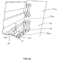
- Figure 2A shows the fastening of the bottom part slats 13a1, 13a2... of the frame mattress bed by a fastening structure 20, a so-called plastic sleeve part, to the inner surface 12' of the frame structure of the side frames 12a1, 12a3 of the frame 12.
- the view is from below towards the slat bottom 13.
- the bottom 13 consists of slats 13a1, 13a2..; 13bl, 13b2...
- Figures 2B and 2C show a second slat 13bn on the surface of the slat 13an, and the sleeve part/sleeve parts 14 surrounding them.
- the sleeve part 14 forming the adjustment mechanism may be freely slid as shown by arrows SI to the desired position along the length of the slats 13an, 13bn, whereby the desired elasticity is achieved.
- the figure represents an example. When the sleeves 14 are on the side of the slat, in relation to its length, the stiffest bundle of slats 13an, 13bn is obtained. When the sleeves 14 are moved towards the centre, there will be more elasticity for the bundle of slats 13an, 13bn.
- sleeve parts 14 used for fixing the slat 13bn to the slat 13an.
- the slats 13a1, 13a2...; 13b1, 13b2... are advantageously of plywood.
- the sleeve part 14 advantageously comprises a locking tongue 14', which by its own spring force connects the sleeve 14 to a particular position along the length of the slats 13an, 13bn (arrows SI).
- the sleeve 14 may also be around the slats by a press-on fit, in which case the tongue 14' is not needed.
- the position of the sleeves 14 determines the combined spring factor, or elasticity, of the bundle of slats.
- the legs may be detachably attached to the frame 12.
- Figures 3 , 4B , 6A, 6B, 6C show the inventive solution to further stiffen a slat bottom.
- FIG 3 shows a strip 21, that is, the stiffening part, fixed to a slat bottom of a frame mattress bed.
- the strip 21 is shown separately.
- the strip 21 is advantageously of felt, plastic, fabric, nonwoven fabric, or cotton wool, or a combination thereof.
- the basic material of the strip is inelastic. Its thickness d is advantageously in the region from 1 mm to 40 mm.
- the basic material layer of the strip 21 is denoted by 21a, and the layer of glue on the strip is denoted by 21b.
- the glue is adhesive glue.
- the layer 21 is pressed onto the surfaces of the slats. This way, the strip 21 locks the slats to each other and stiffens the slat bottom 13 at the spot in question.
- the bottom slats 13a1, 13a2, 13a3,...in the structure are at the top side, and separate second slats 13b1, 13b2, 13b3 attached to them are on the bottom side, and the strip 21 is on the top side of the bottom slats 13a1, 13a2, 13a3,... and locks the desired adjacent bottom slats 13a1, 13a2, 13a3,... to each other.
- the strip 21 is on the bottom side of separate second slats 13b1, 13b2, 13b3,... and thereby locks the desired adjacent separate slats 13b1, 13b2, 13b3,... to each other.
- the bottom slats 13a1, 13a2, 13a3,...in the slat structure are on the bottom side, and separate second slats 13b1, 13b2, 13b3, ... attached to them are at the top side.
- the strip 21 may therefore by either on the top side of the separate slats 13b1, 13b2, 13b3,... or on the bottom side of the bottom slats 13a1, 13a2, 13a3,...
- the strip comprises a layer of adhesive glue 21c on its second surface, too.
- the surface layer in question fixes the mattress in the desired position in relation to the slats and keeps the mattress there.
- the layer 21b placed against the surface of the slats fixes the strip 21 to the slats, and the second top layer 21c fixes the mattress to the strip 21, whereby the mattress stays in the desired position in relation to the slats, as explained.
- the adhesive glue substance is such that the locking may be released and then the locking may again be re-applied.
- adhesive glue it is advantageous to use felt as the basic layer, because glue absorbs well into felt and feeds adhesive glue as surface layers for the entire time the strip is in use.
- the strip 21 may thus be removed and re-attached to the slats in the desired position.
- the strip 21 is cut into form in accordance with the sleeper's surface pressure profile.
- surface pressures and surface pressure chart are evened out, and an even surface pressure distribution is achieved all over the sleeper's area. Therefore the strip 21 is inelastic and flexible. A straight position of the spine of the sleeper is achieved.
- Figures 4A and 4B present the strip 21, as regards its basic material and basic material layer 21a, of inelastic material and structure, such as nonwoven fabric, cotton wool, fabrics, plastic, or felt.
- the advantage of felt is that absorbs glue well, advantageously adhesive glue.
- the strip 21 is attached to the slats with adhesive glue.
- the strip 21 in the embodiment of Figure 4B comprises layers of adhesive glue 21b and 21c on both its surfaces. In such a case, they are the top layers.
- An example not forming part of the invention of Figure 5 is also possible, where the strip 21 is fixed to the slats with rivets 22 or screws 23.
- the thickness d of the strip 21 in all the embodiments is advantageously in the region from 1 mm to 40 mm.
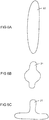
- Figure 6A illustrates the shaping of the strip 21.
- the strip 21 is cut according to the measured surface pressure chart of each individual sleeper, measured with a measuring mattress.
- the strip 21 fixes slats to each other in particular at those spots where the sleeper's surface pressure on the mattress is at its minimum.
- the shape of the strip 21 is cut to have the surface pressure profile of the sleeper's surface pressure chart as even as possible and the sleeper's spine straight.
- the shape of the strip 21 is in the exemplary shaping of Figure 6A pointy and oval-shaped.
- the shape of the strip 21 is pointy at both ends and circularly curved in the middle.
- Figure 6C shows a mushroom-like shape.
- the shape of the strip 21 is chosen sleeper-specifically according to the surface pressure chart. The accompanying shapes are presented by way of example.
Landscapes
- Health & Medical Sciences (AREA)
- Nursing (AREA)
- General Health & Medical Sciences (AREA)
- Life Sciences & Earth Sciences (AREA)
- Animal Behavior & Ethology (AREA)
- Public Health (AREA)
- Veterinary Medicine (AREA)
- Mattresses And Other Support Structures For Chairs And Beds (AREA)
- Invalid Beds And Related Equipment (AREA)
Description
- The invention relates to a motorized bed and a method of forming the motorized bed.
Document DE 20 2011 052353 U1 discloses a mattress that can be swivelled by a motor. - A motorized bed consists of a self-supporting frame structure, supported by which a pivoted slat bottom raised and lowered by a motor is fixed. On the slat bottom, a mattress is placed on top of which a mattress pad is placed. The mattress comprises at least one spring assembly. Advantageously a spring assembly is used, which consists of so-called module springing in which the springing may be selected/changed zone-by-zone along the length of the frame mattress bed. The frame of a frame mattress bed is provided with screw-on legs, for example. The motor or motors adjust the height or tilting position of the movable slat bottom through a mechanism.
- The bed is equipped with an adjustable elastic bottom whose stiffness and consequently elasticity may advantageously be linearly adjusted according to the sleeper and the length of the frame mattress bed. The elastic bottom is advantageously formed of a slat bottom the elasticity of which may be adjusted.
- At least one separate slat is used in connection with the actual bottom slat. The location of the connection points of the separate slat in relation to a second, so-called fixed slat, that is, the actual bottom slat, is adjustable and so the spring leaf type of elasticity of the set of slats may be adjusted. A slat therefore comprises a second slat in connection with it, the fastening position or connection position in relation to the actual bottom slat is adjustable. This adjustment takes place by means of a sleeve member, advantageously two sleeve members, which sleeve member may be freely moved along the length of the slats, the sleeve member thus determining the combined elasticity of the interconnected slats.
- The slats are set to a suitable level of elasticity in relation to each other, and so a stiffer structure, for example, is accomplished at a particular location along the length of the frame mattress bed.
- It is an aim of this application aims to further improve sleep comfort. For elasticity adjustment, the application discloses, in addition to the sleeve members, a covering, that is, a strip or stiffening part to be locked to the slats, which at the same time locks the slats within its scope to each other and further stiffens the structure and slat bottom for their part and at their location.
- It is suggested that a plastic band, felt, fabric or cotton wool be used as the strip or stiffening part, comprising according to the invention on its surface an adhesive glue coating. The other side of the strip according to the invention also comprises a layer of adhesive glue. The strip is pressed against a plurality of slats. In such a case, it locks the slats to each other and stiffens the spot in question in the area of the slats in question. The sleeves may be located under the strip. Since there is a layer of glue on both sides of the strip, one layer of glue attaches the mattress to a desired position in relation to the slats, and the second one keeps the mattress in place.
- The strip may be also be fixed to the slats mechanically, advantageously by rivets or screws. The strip is advantageously of a nonwoven fabric, fabric, plastic, or cotton wool, with the thickness advantageously in the region from 1 mm to 40 mm.
- The shape of the strip is chosen on the basis of a sleeper's pressure profile on the surface of the mattress, so according to a surface pressure chart. The pressure profile is acquired by measuring it on a measuring mattress. The greatest stiffness is placed in the spots where the lowest surface pressure from a person's body falls on the surface of the mattress. The strip is advantageously an inelastic and flexible structural part. When the strip is inelastic, it stiffens the slat bottom at the spots where it detachably connects to the slats. When the strip is flexible, it may be fastened between different slat bottom portions in the slat bottom, where the direction of the slat changes.
- The motorized bed and method according to the invention are characterised by what is disclosed in the independent claims.
- In the following, the invention will be described with reference to preferred embodiments of the invention shown in the accompanying drawings without, however, exclusively restricting it to them.
-
Figure 1A shows a motorized bed and mattress in a raised position of the slat bottom. -
Figure 1B shows a motorized bed with a mattress removed from the top of the slat bottom. -
Figure 1C illustrates a raising mechanism of the slat bottom. -
Figure 1D shows a motorized bed from an end. -
Figure 1E shows a slat bottom of a motorized bed, which comprises an adjustable springing. -
Figure 1F shows a cross-section I-I ofFigure 1D . -
Figure 2A shows a fastening arrangement of two slats to an inner side surface of the body or the frame of the bed. The view is from below the sets of slats. -
Figure 2B shows a slat solution, where the mutual support of the slats to each other may be adjusted by moving the sleeve members. The view is also from below, as in 2A. -
Figure 2C is a principled view of two slats and the sleeve member. -
Figure 3 shows the solution according to the invention in which a detachable strip which locks and stiffens the slats has been placed in connection with the slats. -
Figure 4A shows an example not forming part of the invention of the strip separately. -
Figure 4B shows an embodiment according to the invention where the strip comprises a layer of adhesive glue on both of its surfaces. -
Figure 5 shows an example not forming part of the invention where the strip is fastened to the slats with rivets or screws. -
Figure 6A illustrates a strip shaped according to a sleeper's pressure chart. -
Figure 6B shows an embodiment of shaping the strip, where the strip has been shaped according to the pressure chart of a specific sleeper, with the sleeper's spine straight when he is sleeping. -
Figure 6C shows an embodiment of the shaping of the strip. -
Figures 1A and1B show a motorizedbed 10 axonometrically. It comprises a body, that is, aframe 12 and on top of which amattress 11 of the frame, the height and tilting of which are adjustable by means of a motor or motors M1 and M2 and amechanism 100 by adjusting the position of theslat bottom 13 with the motor M1 and M2, advantageously with an electric motor. On top of themattress 11 there is a mattress pad P. -
Figures 1A and1B show an adjustment position of the position adjustment of the slat bottom. -
Figure 1B show astiffening strip 21 according to the invention on the slat bottom. -
Figure 1C illustrates amoving mechanism 100 of the slat bottom. - The motor M1 rotates an
axle 81, and themotor M2 axle 82, which turn supportarms moving mechanism 100. Thesupport arm 91 connects tobottom portions 130a and 130bn of theslat bottom 13. Thesupport arm 92 connects to abottom portion 130d andbottom portion 130e. Thebottom portions bottom portion 130d is pivoted to thebottom portion bottom portion 130b is pivoted to theframe 12. Thebottom portion 130c is a non-moving portion and fixed to theframe 12. The support arms may be independently moved separately with the motors M1 and M2, which are advantageously electric motors. - The moving
mechanism 100 is supported to the lower part of theframe 12 of themotorized bed 10 with tubular support arms T1 and T2. -
Figure 1D is an end view of themotorized bed 10. -
Figure 1E shows theframe 12 andslat bottom 13 of the motorized bed. The sleeves for adjusting stiffness are placed in an exemplary manner, only, at different positions along the length of a slat. Thestrip 21 according to the invention is placed on top of the slats. -
Figure 1F shows a cross-section I-I ofFigure 1D . The motor M adjusts the height position and tilting of the slat bottom 13 through themechanism 100. - The
motorized bed 10 comprises amattress 11, a self-supporting body of the motorized bed, which is a frame-like part comprising side frame parts 12al, 12a2, 12a3, 12a4 and a slat bottom 13 consisting of slats 13a1, 13a2...13bl, 13b2... shown inFigure 1B . Thelegs frame 12 and may be detachably screwed on it. - The
motorized bed 10 comprises in the mattress 11 aspring assembly 15 formed with modular springs 15a1, 15a2... placed in abag 16 and selectable zone-by-zone according to the weight/build of a sleeper. Thereplaceable spring assembly 15 is located within the foamplastic wall structure 17 of themattress 11. Thetick 18 surrounds theframe 15,spring assembly 17, and the foamplastic parts 17 all over. Thespring assembly 15 is advantageously a structure which consists of springs 15a1, 15a2... in thebags 16 and which may be chosen zone-by-zone to suit the sleeper's build. Below the spring assembly is the slat bottom 13 the elasticity of which may be adjusted. Below the slat bottom 13 there is a free space D. -
Figure 2A shows the fastening of the bottom part slats 13a1, 13a2... of the frame mattress bed by afastening structure 20, a so-called plastic sleeve part, to the inner surface 12' of the frame structure of the side frames 12a1, 12a3 of theframe 12. The view is from below towards theslat bottom 13. The bottom 13 consists of slats 13a1, 13a2..; 13bl, 13b2... -
Figures 2B and2C show a second slat 13bn on the surface of the slat 13an, and the sleeve part/sleeve parts 14 surrounding them. Thesleeve part 14 forming the adjustment mechanism may be freely slid as shown by arrows SI to the desired position along the length of the slats 13an, 13bn, whereby the desired elasticity is achieved. The figure represents an example. When thesleeves 14 are on the side of the slat, in relation to its length, the stiffest bundle of slats 13an, 13bn is obtained. When thesleeves 14 are moved towards the centre, there will be more elasticity for the bundle of slats 13an, 13bn. There are advantageously two ormore sleeve parts 14 used for fixing the slat 13bn to the slat 13an. There may be asleeve part 14 and slat 13bn in connection with all the slats 13an or just some of them. This way, different variations are achieved for linearly adjusting the stiffness for the set of slats 13al, 13bl, 13a2, 13b2, 13a3, 13b3... 13an, 13bn. The slats 13a1, 13a2...; 13b1, 13b2... are advantageously of plywood. Thesleeve part 14 advantageously comprises a locking tongue 14', which by its own spring force connects thesleeve 14 to a particular position along the length of the slats 13an, 13bn (arrows SI). Thesleeve 14 may also be around the slats by a press-on fit, in which case the tongue 14' is not needed. The position of thesleeves 14 determines the combined spring factor, or elasticity, of the bundle of slats. The legs may be detachably attached to theframe 12. -
Figures 3 ,4B ,6A, 6B, 6C show the inventive solution to further stiffen a slat bottom. -
Figure 3 shows astrip 21, that is, the stiffening part, fixed to a slat bottom of a frame mattress bed. In the example not forming part of the invention ofFigure 4A , thestrip 21 is shown separately. Thestrip 21 is advantageously of felt, plastic, fabric, nonwoven fabric, or cotton wool, or a combination thereof. The basic material of the strip is inelastic. Its thickness d is advantageously in the region from 1 mm to 40 mm. The basic material layer of thestrip 21 is denoted by 21a, and the layer of glue on the strip is denoted by 21b. The glue is adhesive glue. Thelayer 21 is pressed onto the surfaces of the slats. This way, thestrip 21 locks the slats to each other and stiffens the slat bottom 13 at the spot in question. - In the embodiment disclosed in this context, the bottom slats 13a1, 13a2, 13a3,...in the structure are at the top side, and separate second slats 13b1, 13b2, 13b3 attached to them are on the bottom side, and the
strip 21 is on the top side of the bottom slats 13a1, 13a2, 13a3,... and locks the desired adjacent bottom slats 13a1, 13a2, 13a3,... to each other. An embodiment is also possible where thestrip 21 is on the bottom side of separate second slats 13b1, 13b2, 13b3,... and thereby locks the desired adjacent separate slats 13b1, 13b2, 13b3,... to each other. Likewise, such embodiments are possible where the bottom slats 13a1, 13a2, 13a3,...in the slat structure are on the bottom side, and separate second slats 13b1, 13b2, 13b3, ... attached to them are at the top side. Thestrip 21 may therefore by either on the top side of the separate slats 13b1, 13b2, 13b3,... or on the bottom side of the bottom slats 13a1, 13a2, 13a3,... - According to the invention, see
Fig. 4B , the strip comprises a layer ofadhesive glue 21c on its second surface, too. The surface layer in question fixes the mattress in the desired position in relation to the slats and keeps the mattress there. Thelayer 21b placed against the surface of the slats fixes thestrip 21 to the slats, and the secondtop layer 21c fixes the mattress to thestrip 21, whereby the mattress stays in the desired position in relation to the slats, as explained. - The adhesive glue substance is such that the locking may be released and then the locking may again be re-applied. In connection with adhesive glue, it is advantageous to use felt as the basic layer, because glue absorbs well into felt and feeds adhesive glue as surface layers for the entire time the strip is in use.
- Felt feeds glue well onto the surface of the basic layer. The
strip 21 may thus be removed and re-attached to the slats in the desired position. Thestrip 21 is cut into form in accordance with the sleeper's surface pressure profile. By means of thestrip 21, surface pressures and surface pressure chart are evened out, and an even surface pressure distribution is achieved all over the sleeper's area. Therefore thestrip 21 is inelastic and flexible. A straight position of the spine of the sleeper is achieved. -
Figures 4A and4B present thestrip 21, as regards its basic material andbasic material layer 21a, of inelastic material and structure, such as nonwoven fabric, cotton wool, fabrics, plastic, or felt. The advantage of felt is that absorbs glue well, advantageously adhesive glue. Thestrip 21 is attached to the slats with adhesive glue. Thestrip 21 in the embodiment ofFigure 4B comprises layers ofadhesive glue Figure 5 is also possible, where thestrip 21 is fixed to the slats withrivets 22 or screws 23. The thickness d of thestrip 21 in all the embodiments is advantageously in the region from 1 mm to 40 mm. -
Figure 6A illustrates the shaping of thestrip 21. Thestrip 21 is cut according to the measured surface pressure chart of each individual sleeper, measured with a measuring mattress. Thestrip 21 fixes slats to each other in particular at those spots where the sleeper's surface pressure on the mattress is at its minimum. The shape of thestrip 21 is cut to have the surface pressure profile of the sleeper's surface pressure chart as even as possible and the sleeper's spine straight. The shape of thestrip 21 is in the exemplary shaping ofFigure 6A pointy and oval-shaped. - In
Figure 6B , the shape of thestrip 21 is pointy at both ends and circularly curved in the middle.Figure 6C shows a mushroom-like shape. The shape of thestrip 21 is chosen sleeper-specifically according to the surface pressure chart. The accompanying shapes are presented by way of example. - A person skilled in the art will find it obvious that, as technology advances, the basic idea of the invention may be implemented in many different ways. The invention and its embodiments are thus not restricted to the above-described examples but may vary within the scope of the claims.
Claims (7)
- A motorized bed (10) comprising a self-supporting frame and, in connection with it, a slat bottom (13) on top of which a mattress may be adapted, and a motor (M1, M2) for moving the slat bottom (13), the slat bottom (13) comprising a plurality of first slats (13a1, 13a2, ...) and at least one second slat (13b1, 13b2, ...), wherein the second slat (13b1, 13b2, ...) is attached to one of the first slats (13a1, 13a2, ...) by means of a sleeve member (14), wherein by changing the position of the sleeve member (14) along the length of the interconnected first and second slats (13a1, 13a2, ...; 13b1, 13b2, ...) the combined elasticity of the interconnected first and second slats (13a1, 13a2, ...; 13b1, 13b2, ...) is adjusted,wherein the motorized bed (10) further comprises a strip (21), that is, a stiffening part which is detachably attached to a surface of the first or second slats (13a1, 13a2, ...; 13b1, 13b2, ...), wherein the strip (21) locks the first or second slats (13a1, 13a2, ...; 13b1, 13b2, ...) to each other and adds to the stiffness of the slat bottom (13) at the spot in question,characterised in that the strip (21) comprises a first surface on one side and a second surface on the other side, wherein both surfaces of the strip (21) comprise a layer of adhesive glue (21b, 21c), the first surface of the strip (21) comes against the surface of the first or second slats (13a1, 13a2, ...; 13b1, 13b2, ...) and the second surface of the strip (21) is configured to lock the mattress into a specific position on the first or second slats (13al, 13a2, ...; 13bl, 13b2, ...).
- A motorized bed (10) as claimed in claim 1, characterised in that
the strip (21) is an inelastic and flexible structure, and its thickness (d) is advantageously in the region from 1 mm to 40 mm. - A motorized bed (10) as claimed in claim 1 or 2, characterised in that
a basic material (21a) of the strip (21) is fabric, felt, plastic, or cotton wool, and that the strip (21) is of inelastic material. - A motorized bed (10) as claimed in any one of the preceding claims, characterised in that there is a mechanical fastener, such as a rivet (22) or screw (23), with which the strip (21) is fixed to a slat.
- A motorized bed (10) as claimed in any one of the preceding claims, characterised in that
the shape of the strip (21) is determined on the basis of a measured sleeper's surface pressure chart. - A method of forming the motorized bed of claim 1, the method comprising:providing the self-supporting frame, the slat bottom (13) in connection with it, on top of which a mattress may be adapted, and the motor (M1, M2) to move the slat bottom (13),attaching the second slat (13b1, 13b2,...) to the first slat (13a1, 13a2,...) of the slat bottom (13) by means of the sleeve member (14), wherein by changing the position of the sleeve member (14) along the length of the interconnected first and second slats (13a1, 13a2, ...; 13b1, 13b2, ...) the combined elasticity of the interconnected first and second slats (13a1, 13a2, ...; 13b1, 13b2, ...) is adjusted,attaching detachably the strip (21) on top of the first or second slats (13a1, 13a2, ...; 13b1, 13b2, ...) to lock the first or second slats (13a1, 13a2, ...; 13b1, 13b2, ...) to each other and to add to the stiffness of the slat bottom (13) at the spot in question.
- A method as claimed in claim 6 in which method a sleeper's surface pressure chart is measured and the shape of the strip (21) is determined on the basis of the measured surface pressure chart.
Applications Claiming Priority (2)
| Application Number | Priority Date | Filing Date | Title |
|---|---|---|---|
| FIU20174028U FI12056U1 (en) | 2017-02-06 | 2017-02-06 | Adjustable bed and stiffening member for an adjustable bed |
| PCT/FI2018/050081 WO2018142030A1 (en) | 2017-02-06 | 2018-02-05 | Motorized bed, stiffening part for a motorized bed and method of forming a motorized bed |
Publications (3)
| Publication Number | Publication Date |
|---|---|
| EP3576576A1 EP3576576A1 (en) | 2019-12-11 |
| EP3576576A4 EP3576576A4 (en) | 2020-08-05 |
| EP3576576B1 true EP3576576B1 (en) | 2021-10-27 |
Family
ID=62527725
Family Applications (1)
| Application Number | Title | Priority Date | Filing Date |
|---|---|---|---|
| EP18747411.9A Active EP3576576B1 (en) | 2017-02-06 | 2018-02-05 | Motorized bed and method of forming the motorized bed |
Country Status (6)
| Country | Link |
|---|---|
| EP (1) | EP3576576B1 (en) |
| DK (1) | DK3576576T3 (en) |
| ES (1) | ES2902892T3 (en) |
| FI (1) | FI12056U1 (en) |
| LT (1) | LT3576576T (en) |
| WO (1) | WO2018142030A1 (en) |
Families Citing this family (1)
| Publication number | Priority date | Publication date | Assignee | Title |
|---|---|---|---|---|
| US12013125B2 (en) * | 2021-08-11 | 2024-06-18 | Green Earth Regeneration (Xiamen) Environmental Technology Co., Ltd. | Fire pit |
Family Cites Families (7)
| Publication number | Priority date | Publication date | Assignee | Title |
|---|---|---|---|---|
| DE29714120U1 (en) * | 1997-08-07 | 1997-10-02 | Rössle & Wanner GmbH, 72116 Mössingen | Slatted frame with reinforcement band unit |
| AT2645U1 (en) * | 1998-09-14 | 1999-02-25 | Das Bett Moebelhandels Gmbh | Slatted frame with insert frame especially for seating and reclining furniture |
| DE20001452U1 (en) * | 2000-01-28 | 2000-05-18 | Jelinek, Michael, 92421 Schwandorf | Rolling frame |
| DE20304868U1 (en) * | 2002-06-27 | 2003-11-06 | Cimosys Ag, Goldingen | Adjustment device for hospital beds and seating, has bend- or kink-compensating members positioned between each two adjacent rail members |
| FI119865B (en) * | 2007-03-30 | 2009-04-30 | Unikulma Oy | mattress structure |
| DE202008000406U1 (en) * | 2008-01-09 | 2008-03-20 | Holhut, Peter | Special spring suspension for beds and bed systems |
| DE202011052353U1 (en) * | 2011-12-19 | 2013-03-21 | Recticel Schlafkomfort Gmbh | mattress |
-
2017
- 2017-02-06 FI FIU20174028U patent/FI12056U1/en active IP Right Grant
-
2018
- 2018-02-05 ES ES18747411T patent/ES2902892T3/en active Active
- 2018-02-05 DK DK18747411.9T patent/DK3576576T3/en active
- 2018-02-05 LT LTEPPCT/FI2018/050081T patent/LT3576576T/en unknown
- 2018-02-05 WO PCT/FI2018/050081 patent/WO2018142030A1/en unknown
- 2018-02-05 EP EP18747411.9A patent/EP3576576B1/en active Active
Also Published As
| Publication number | Publication date |
|---|---|
| DK3576576T3 (en) | 2022-01-17 |
| EP3576576A4 (en) | 2020-08-05 |
| ES2902892T3 (en) | 2022-03-30 |
| FI12056U1 (en) | 2018-06-15 |
| LT3576576T (en) | 2022-01-10 |
| EP3576576A1 (en) | 2019-12-11 |
| WO2018142030A1 (en) | 2018-08-09 |
Similar Documents
| Publication | Publication Date | Title |
|---|---|---|
| US7559607B2 (en) | Adjustable ergonomic back for a seat | |
| EP3097823B1 (en) | Plunger for a plunger matrix mattress | |
| US4827544A (en) | Reclining and lying means, particularly for a bed | |
| US6742205B2 (en) | Adjustable padding device for a piece of furniture used for sitting and/or lying upon | |
| DK2874519T3 (en) | Bed with joints with flexible mattress support. | |
| RU2653474C2 (en) | Furniture device with adjustable firmness | |
| EP3079527B1 (en) | Vibratory system for massage and audio generation in an articulating bed | |
| FI93514B (en) | By the bottom | |
| EP0608635B1 (en) | A bed base structure | |
| EP3576576B1 (en) | Motorized bed and method of forming the motorized bed | |
| CN105101845A (en) | Chair with activated back flex | |
| US5214809A (en) | Articulated mattress for adjustable bed | |
| EP3576577B1 (en) | Frame mattress bed and method of forming the frame mattress bed | |
| DK2503976T3 (en) | A deformable support element and lying system | |
| CN111727024A (en) | Head support device | |
| NL2005885C2 (en) | Support for a mattress and bed comprising such support. | |
| JPH0626524B2 (en) | Chair back | |
| US20180220805A1 (en) | Vibration motor assembly for bed facility | |
| JP7044691B2 (en) | Optional receiver and body support | |
| CN113905636A (en) | Furniture device for a piece of furniture | |
| EP0699406A1 (en) | A combination of a mattress and a bed frame | |
| EP3865011B1 (en) | Device for adjusting the stiffness of a sprung slat | |
| US330293A (en) | Spring bed-bottom | |
| BE1018284A3 (en) | BOTTOM FOR SUPPORTING A MATTRESS OF A BED OR THE LIKE. | |
| US662487A (en) | Invalid-bed. |
Legal Events
| Date | Code | Title | Description |
|---|---|---|---|
| STAA | Information on the status of an ep patent application or granted ep patent |
Free format text: STATUS: THE INTERNATIONAL PUBLICATION HAS BEEN MADE |
|
| PUAI | Public reference made under article 153(3) epc to a published international application that has entered the european phase |
Free format text: ORIGINAL CODE: 0009012 |
|
| STAA | Information on the status of an ep patent application or granted ep patent |
Free format text: STATUS: REQUEST FOR EXAMINATION WAS MADE |
|
| 17P | Request for examination filed |
Effective date: 20190905 |
|
| AK | Designated contracting states |
Kind code of ref document: A1 Designated state(s): AL AT BE BG CH CY CZ DE DK EE ES FI FR GB GR HR HU IE IS IT LI LT LU LV MC MK MT NL NO PL PT RO RS SE SI SK SM TR |
|
| AX | Request for extension of the european patent |
Extension state: BA ME |
|
| DAV | Request for validation of the european patent (deleted) | ||
| DAX | Request for extension of the european patent (deleted) | ||
| REG | Reference to a national code |
Ref country code: DE Ref legal event code: R079 Ref document number: 602018025728 Country of ref document: DE Free format text: PREVIOUS MAIN CLASS: A47C0020040000 Ipc: A47C0023300000 |
|
| A4 | Supplementary search report drawn up and despatched |
Effective date: 20200707 |
|
| RIC1 | Information provided on ipc code assigned before grant |
Ipc: A61G 7/05 20060101ALI20200701BHEP Ipc: A47C 23/06 20060101ALI20200701BHEP Ipc: A47C 23/30 20060101AFI20200701BHEP Ipc: A47C 20/08 20060101ALI20200701BHEP Ipc: A47C 20/04 20060101ALI20200701BHEP |
|
| GRAP | Despatch of communication of intention to grant a patent |
Free format text: ORIGINAL CODE: EPIDOSNIGR1 |
|
| STAA | Information on the status of an ep patent application or granted ep patent |
Free format text: STATUS: GRANT OF PATENT IS INTENDED |
|
| INTG | Intention to grant announced |
Effective date: 20210520 |
|
| GRAS | Grant fee paid |
Free format text: ORIGINAL CODE: EPIDOSNIGR3 |
|
| GRAA | (expected) grant |
Free format text: ORIGINAL CODE: 0009210 |
|
| STAA | Information on the status of an ep patent application or granted ep patent |
Free format text: STATUS: THE PATENT HAS BEEN GRANTED |
|
| AK | Designated contracting states |
Kind code of ref document: B1 Designated state(s): AL AT BE BG CH CY CZ DE DK EE ES FI FR GB GR HR HU IE IS IT LI LT LU LV MC MK MT NL NO PL PT RO RS SE SI SK SM TR |
|
| RAP3 | Party data changed (applicant data changed or rights of an application transferred) |
Owner name: UNIKULMA OY |
|
| REG | Reference to a national code |
Ref country code: GB Ref legal event code: FG4D |
|
| REG | Reference to a national code |
Ref country code: CH Ref legal event code: EP |
|
| REG | Reference to a national code |
Ref country code: AT Ref legal event code: REF Ref document number: 1441058 Country of ref document: AT Kind code of ref document: T Effective date: 20211115 |
|
| REG | Reference to a national code |
Ref country code: DE Ref legal event code: R096 Ref document number: 602018025728 Country of ref document: DE |
|
| REG | Reference to a national code |
Ref country code: IE Ref legal event code: FG4D |
|
| REG | Reference to a national code |
Ref country code: DK Ref legal event code: T3 Effective date: 20220110 |
|
| REG | Reference to a national code |
Ref country code: FI Ref legal event code: FGE Ref country code: SE Ref legal event code: TRGR |
|
| REG | Reference to a national code |
Ref country code: NL Ref legal event code: FP |
|
| REG | Reference to a national code |
Ref country code: EE Ref legal event code: FG4A Ref document number: E021731 Country of ref document: EE Effective date: 20211230 |
|
| REG | Reference to a national code |
Ref country code: NO Ref legal event code: T2 Effective date: 20211027 |
|
| REG | Reference to a national code |
Ref country code: AT Ref legal event code: MK05 Ref document number: 1441058 Country of ref document: AT Kind code of ref document: T Effective date: 20211027 |
|
| REG | Reference to a national code |
Ref country code: ES Ref legal event code: FG2A Ref document number: 2902892 Country of ref document: ES Kind code of ref document: T3 Effective date: 20220330 |
|
| PG25 | Lapsed in a contracting state [announced via postgrant information from national office to epo] |
Ref country code: RS Free format text: LAPSE BECAUSE OF FAILURE TO SUBMIT A TRANSLATION OF THE DESCRIPTION OR TO PAY THE FEE WITHIN THE PRESCRIBED TIME-LIMIT Effective date: 20211027 Ref country code: BG Free format text: LAPSE BECAUSE OF FAILURE TO SUBMIT A TRANSLATION OF THE DESCRIPTION OR TO PAY THE FEE WITHIN THE PRESCRIBED TIME-LIMIT Effective date: 20220127 Ref country code: AT Free format text: LAPSE BECAUSE OF FAILURE TO SUBMIT A TRANSLATION OF THE DESCRIPTION OR TO PAY THE FEE WITHIN THE PRESCRIBED TIME-LIMIT Effective date: 20211027 |
|
| PG25 | Lapsed in a contracting state [announced via postgrant information from national office to epo] |
Ref country code: IS Free format text: LAPSE BECAUSE OF FAILURE TO SUBMIT A TRANSLATION OF THE DESCRIPTION OR TO PAY THE FEE WITHIN THE PRESCRIBED TIME-LIMIT Effective date: 20220227 Ref country code: PT Free format text: LAPSE BECAUSE OF FAILURE TO SUBMIT A TRANSLATION OF THE DESCRIPTION OR TO PAY THE FEE WITHIN THE PRESCRIBED TIME-LIMIT Effective date: 20220228 Ref country code: PL Free format text: LAPSE BECAUSE OF FAILURE TO SUBMIT A TRANSLATION OF THE DESCRIPTION OR TO PAY THE FEE WITHIN THE PRESCRIBED TIME-LIMIT Effective date: 20211027 Ref country code: HR Free format text: LAPSE BECAUSE OF FAILURE TO SUBMIT A TRANSLATION OF THE DESCRIPTION OR TO PAY THE FEE WITHIN THE PRESCRIBED TIME-LIMIT Effective date: 20211027 Ref country code: GR Free format text: LAPSE BECAUSE OF FAILURE TO SUBMIT A TRANSLATION OF THE DESCRIPTION OR TO PAY THE FEE WITHIN THE PRESCRIBED TIME-LIMIT Effective date: 20220128 |
|
| REG | Reference to a national code |
Ref country code: DE Ref legal event code: R097 Ref document number: 602018025728 Country of ref document: DE |
|
| PG25 | Lapsed in a contracting state [announced via postgrant information from national office to epo] |
Ref country code: SM Free format text: LAPSE BECAUSE OF FAILURE TO SUBMIT A TRANSLATION OF THE DESCRIPTION OR TO PAY THE FEE WITHIN THE PRESCRIBED TIME-LIMIT Effective date: 20211027 Ref country code: SK Free format text: LAPSE BECAUSE OF FAILURE TO SUBMIT A TRANSLATION OF THE DESCRIPTION OR TO PAY THE FEE WITHIN THE PRESCRIBED TIME-LIMIT Effective date: 20211027 Ref country code: RO Free format text: LAPSE BECAUSE OF FAILURE TO SUBMIT A TRANSLATION OF THE DESCRIPTION OR TO PAY THE FEE WITHIN THE PRESCRIBED TIME-LIMIT Effective date: 20211027 Ref country code: CZ Free format text: LAPSE BECAUSE OF FAILURE TO SUBMIT A TRANSLATION OF THE DESCRIPTION OR TO PAY THE FEE WITHIN THE PRESCRIBED TIME-LIMIT Effective date: 20211027 |
|
| PLBE | No opposition filed within time limit |
Free format text: ORIGINAL CODE: 0009261 |
|
| STAA | Information on the status of an ep patent application or granted ep patent |
Free format text: STATUS: NO OPPOSITION FILED WITHIN TIME LIMIT |
|
| PG25 | Lapsed in a contracting state [announced via postgrant information from national office to epo] |
Ref country code: MC Free format text: LAPSE BECAUSE OF FAILURE TO SUBMIT A TRANSLATION OF THE DESCRIPTION OR TO PAY THE FEE WITHIN THE PRESCRIBED TIME-LIMIT Effective date: 20211027 |
|
| 26N | No opposition filed |
Effective date: 20220728 |
|
| PG25 | Lapsed in a contracting state [announced via postgrant information from national office to epo] |
Ref country code: LU Free format text: LAPSE BECAUSE OF NON-PAYMENT OF DUE FEES Effective date: 20220205 Ref country code: AL Free format text: LAPSE BECAUSE OF FAILURE TO SUBMIT A TRANSLATION OF THE DESCRIPTION OR TO PAY THE FEE WITHIN THE PRESCRIBED TIME-LIMIT Effective date: 20211027 |
|
| PG25 | Lapsed in a contracting state [announced via postgrant information from national office to epo] |
Ref country code: SI Free format text: LAPSE BECAUSE OF FAILURE TO SUBMIT A TRANSLATION OF THE DESCRIPTION OR TO PAY THE FEE WITHIN THE PRESCRIBED TIME-LIMIT Effective date: 20211027 |
|
| PGFP | Annual fee paid to national office [announced via postgrant information from national office to epo] |
Ref country code: NL Payment date: 20240115 Year of fee payment: 7 |
|
| PGFP | Annual fee paid to national office [announced via postgrant information from national office to epo] |
Ref country code: LT Payment date: 20240115 Year of fee payment: 7 |
|
| PGFP | Annual fee paid to national office [announced via postgrant information from national office to epo] |
Ref country code: ES Payment date: 20240318 Year of fee payment: 7 Ref country code: IE Payment date: 20240115 Year of fee payment: 7 |
|
| PG25 | Lapsed in a contracting state [announced via postgrant information from national office to epo] |
Ref country code: MK Free format text: LAPSE BECAUSE OF FAILURE TO SUBMIT A TRANSLATION OF THE DESCRIPTION OR TO PAY THE FEE WITHIN THE PRESCRIBED TIME-LIMIT Effective date: 20211027 Ref country code: CY Free format text: LAPSE BECAUSE OF FAILURE TO SUBMIT A TRANSLATION OF THE DESCRIPTION OR TO PAY THE FEE WITHIN THE PRESCRIBED TIME-LIMIT Effective date: 20211027 |
|
| PGFP | Annual fee paid to national office [announced via postgrant information from national office to epo] |
Ref country code: FI Payment date: 20240115 Year of fee payment: 7 Ref country code: EE Payment date: 20240115 Year of fee payment: 7 Ref country code: DE Payment date: 20240115 Year of fee payment: 7 Ref country code: GB Payment date: 20240116 Year of fee payment: 7 Ref country code: CH Payment date: 20240301 Year of fee payment: 7 |
|
| PG25 | Lapsed in a contracting state [announced via postgrant information from national office to epo] |
Ref country code: HU Free format text: LAPSE BECAUSE OF FAILURE TO SUBMIT A TRANSLATION OF THE DESCRIPTION OR TO PAY THE FEE WITHIN THE PRESCRIBED TIME-LIMIT; INVALID AB INITIO Effective date: 20180205 |
|
| PGFP | Annual fee paid to national office [announced via postgrant information from national office to epo] |
Ref country code: SE Payment date: 20240118 Year of fee payment: 7 Ref country code: NO Payment date: 20240115 Year of fee payment: 7 Ref country code: LV Payment date: 20240115 Year of fee payment: 7 Ref country code: IT Payment date: 20240115 Year of fee payment: 7 Ref country code: FR Payment date: 20240118 Year of fee payment: 7 Ref country code: DK Payment date: 20240118 Year of fee payment: 7 Ref country code: BE Payment date: 20240115 Year of fee payment: 7 |