EP3576405A1 - Video recording control device, method and program - Google Patents
Video recording control device, method and program Download PDFInfo
- Publication number
- EP3576405A1 EP3576405A1 EP17894107.6A EP17894107A EP3576405A1 EP 3576405 A1 EP3576405 A1 EP 3576405A1 EP 17894107 A EP17894107 A EP 17894107A EP 3576405 A1 EP3576405 A1 EP 3576405A1
- Authority
- EP
- European Patent Office
- Prior art keywords
- recording
- video image
- processing unit
- image data
- mode
- Prior art date
- Legal status (The legal status is an assumption and is not a legal conclusion. Google has not performed a legal analysis and makes no representation as to the accuracy of the status listed.)
- Granted
Links
Images


Classifications
-
- H—ELECTRICITY
- H04—ELECTRIC COMMUNICATION TECHNIQUE
- H04N—PICTORIAL COMMUNICATION, e.g. TELEVISION
- H04N5/00—Details of television systems
- H04N5/76—Television signal recording
-
- G—PHYSICS
- G11—INFORMATION STORAGE
- G11B—INFORMATION STORAGE BASED ON RELATIVE MOVEMENT BETWEEN RECORD CARRIER AND TRANSDUCER
- G11B19/00—Driving, starting, stopping record carriers not specifically of filamentary or web form, or of supports therefor; Control thereof; Control of operating function ; Driving both disc and head
- G11B19/02—Control of operating function, e.g. switching from recording to reproducing
- G11B19/04—Arrangements for preventing, inhibiting, or warning against double recording on the same blank or against other recording or reproducing malfunctions
- G11B19/041—Detection or prevention of read or write errors
-
- B—PERFORMING OPERATIONS; TRANSPORTING
- B60—VEHICLES IN GENERAL
- B60Q—ARRANGEMENT OF SIGNALLING OR LIGHTING DEVICES, THE MOUNTING OR SUPPORTING THEREOF OR CIRCUITS THEREFOR, FOR VEHICLES IN GENERAL
- B60Q1/00—Arrangement of optical signalling or lighting devices, the mounting or supporting thereof or circuits therefor
-
- G—PHYSICS
- G06—COMPUTING OR CALCULATING; COUNTING
- G06F—ELECTRIC DIGITAL DATA PROCESSING
- G06F12/00—Accessing, addressing or allocating within memory systems or architectures
- G06F12/16—Protection against loss of memory contents
-
- G—PHYSICS
- G07—CHECKING-DEVICES
- G07C—TIME OR ATTENDANCE REGISTERS; REGISTERING OR INDICATING THE WORKING OF MACHINES; GENERATING RANDOM NUMBERS; VOTING OR LOTTERY APPARATUS; ARRANGEMENTS, SYSTEMS OR APPARATUS FOR CHECKING NOT PROVIDED FOR ELSEWHERE
- G07C5/00—Registering or indicating the working of vehicles
- G07C5/08—Registering or indicating performance data other than driving, working, idle, or waiting time, with or without registering driving, working, idle or waiting time
- G07C5/0841—Registering performance data
- G07C5/085—Registering performance data using electronic data carriers
- G07C5/0866—Registering performance data using electronic data carriers the electronic data carrier being a digital video recorder in combination with video camera
-
- G—PHYSICS
- G08—SIGNALLING
- G08B—SIGNALLING SYSTEMS, e.g. PERSONAL CALLING SYSTEMS; ORDER TELEGRAPHS; ALARM SYSTEMS
- G08B21/00—Alarms responsive to a single specified undesired or abnormal condition and not otherwise provided for
-
- G—PHYSICS
- G11—INFORMATION STORAGE
- G11B—INFORMATION STORAGE BASED ON RELATIVE MOVEMENT BETWEEN RECORD CARRIER AND TRANSDUCER
- G11B19/00—Driving, starting, stopping record carriers not specifically of filamentary or web form, or of supports therefor; Control thereof; Control of operating function ; Driving both disc and head
- G11B19/02—Control of operating function, e.g. switching from recording to reproducing
- G11B19/06—Control of operating function, e.g. switching from recording to reproducing by counting or timing of machine operations
-
- H—ELECTRICITY
- H04—ELECTRIC COMMUNICATION TECHNIQUE
- H04N—PICTORIAL COMMUNICATION, e.g. TELEVISION
- H04N5/00—Details of television systems
- H04N5/76—Television signal recording
- H04N5/907—Television signal recording using static stores, e.g. storage tubes or semiconductor memories
-
- B—PERFORMING OPERATIONS; TRANSPORTING
- B60—VEHICLES IN GENERAL
- B60Q—ARRANGEMENT OF SIGNALLING OR LIGHTING DEVICES, THE MOUNTING OR SUPPORTING THEREOF OR CIRCUITS THEREFOR, FOR VEHICLES IN GENERAL
- B60Q9/00—Arrangement or adaptation of signal devices not provided for in one of main groups B60Q1/00 - B60Q7/00, e.g. haptic signalling
-
- H—ELECTRICITY
- H04—ELECTRIC COMMUNICATION TECHNIQUE
- H04N—PICTORIAL COMMUNICATION, e.g. TELEVISION
- H04N5/00—Details of television systems
- H04N5/76—Television signal recording
- H04N5/765—Interface circuits between an apparatus for recording and another apparatus
- H04N5/77—Interface circuits between an apparatus for recording and another apparatus between a recording apparatus and a television camera
-
- H—ELECTRICITY
- H04—ELECTRIC COMMUNICATION TECHNIQUE
- H04N—PICTORIAL COMMUNICATION, e.g. TELEVISION
- H04N7/00—Television systems
- H04N7/18—Closed-circuit television [CCTV] systems, i.e. systems in which the video signal is not broadcast
Definitions
- the present disclosure relates to a video image recording control apparatus, a video image recording control method, and a video image recording control program.
- a drive recorder that is mounted on a vehicle and mainly records video images in front of the vehicle records video images in two modes, that is, a loop recording mode and an event recording mode.
- the loop recording mode is a mode for constantly recording video images captured during the driving.
- the event recording mode is a mode for recording video images captured when an abnormality such as an accident or sudden braking has been detected. Since the event recording is important as information on an accident or an incident, the video images are recorded as overwrite-prohibited data separately from the loop recording.
- An SD card is often used as a storage element for such recording.
- Patent Literature 1 discloses a drive recorder in which a warning is given to a user by an operation lamp 28 and a buzzer 29 when the number of rewrites in a memory card 9 has reached the upper limit and the user is notified that the number of rewrites in the memory card 9 has reached the upper limit. Further, an image processing apparatus disclosed in Patent Literature 2 prohibits rewriting when it is determined that a NAND memory has reached the end of its life.
- Patent Literature 1 the technique disclosed in Patent Literature 1 is only alarm means, and the SD card ends up being used even after the number of rewrites in the SD card exceeds the rewrite restricted number unless the user replaces the SD card by another one in accordance with the alarm information.
- the SD card continues to be used even after the number of rewrites in the SD card exceeds the rewrite restricted number in the SD card, a problem such that an important scene such as an event has not been recorded may occur.
- writing that is, recording itself is prohibited when the memory has reached the end of its life like in Patent Literature 2, the event recording cannot be performed and the drive recorder function cannot be achieved.
- This embodiment has been made in view of the aforementioned problems, and aims to provide a video image recording control apparatus, a video image recording control method, and a video image recording control program for appropriately controlling a recording mode when the end of a rewrite life of a recording apparatus has approached.
- a first aspect of this embodiment provides a video image recording control apparatus including: a recording processing unit configured to record video image data in a recording apparatus by a first recording mode in which video image data captured by an image pickup apparatus is recorded and a second recording mode in which video image data captured when an abnormality has been detected is recorded separately from the first recording mode; and a recording controller configured to restrict the first recording mode for the recording processing unit when the number of times of data rewriting for the recording apparatus has exceeded a first threshold.
- a second aspect of this embodiment provides a video image recording control apparatus including: a recording processing unit configured to record video image data in a recording apparatus by a first recording mode in which video image data captured by an image pickup apparatus is recorded and a second recording mode in which video image data captured when an abnormality has been detected is recorded separately from the first recording mode; and a recording controller configured to restrict the first recording mode for the recording processing unit when it is determined that the life of the recording apparatus has exceeded a predetermined value.
- a third aspect of this embodiment provides a video image recording control method in a video image recording control apparatus including: a recording processing unit configured to record video image data in a recording apparatus by a first recording mode in which video image data captured by an image pickup apparatus is recorded and a second recording mode in which video image data captured when an abnormality has been detected is recorded separately from the first recording mode; and a recording controller configured to perform control on the recording processing unit, the method including the steps of: determining whether the number of times of data rewriting for the recording apparatus has exceeded a first threshold; and restricting the first recording mode for the recording processing unit when it is determined that the number of times of data rewriting for the recording apparatus has exceeded the first threshold.
- a fourth aspect of this embodiment provides a video image recording control program for causing a computer including: a recording processing unit configured to record video image data in a recording apparatus by a first recording mode in which video image data captured by an image pickup apparatus is recorded and a second recording mode in which video image data captured when an abnormality has been detected is recorded separately from the first recording mode; and a recording controller configured to perform control on the recording processing unit, to execute the following steps of: determining whether the number of times of data rewriting for the recording apparatus has exceeded a first threshold; and restricting the first recording mode for the recording processing unit when it is determined that the number of times of data rewriting for the recording apparatus has exceeded the first threshold.
- a video image recording control apparatus capable of performing important recording by appropriately controlling a recording mode when the end of a rewrite life of a recording apparatus has approached and maintaining the life of the recording apparatus.
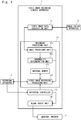
- Fig. 1 is a block diagram showing a configuration of a video image recording control apparatus 1 according to a first embodiment.
- the video image recording control apparatus 1 is connected to an image pickup apparatus 2, a recording apparatus 3, and a monitor and a speaker 4.
- the video image recording control apparatus 1 is, for example, a drive recorder mounted on a moving body such as a vehicle.
- the video image recording control apparatus 1 according to this embodiment is not limited to an in-vehicle drive recorder.
- the image pickup apparatus 2 is, for example, an in-vehicle camera or the like that captures images in front of the vehicle and outputs video image data.
- the recording apparatus 3, which is an external storage device, is, for example, an SD card, a USB memory, a hard disk, or a semiconductor memory.
- the recording apparatus 3 may be embedded in the video image recording control apparatus 1. It is further assumed that the recording apparatus 3 updates the number of times of data rewriting held therein every time the data is rewritten.
- the monitor and the speaker 4 are examples of alarm means for outputting alarm information to a driver or the like of the vehicle by means of voice, buzzer, screen display or the like.
- the video image recording control apparatus 1 includes a video image data acquisition unit 11, a recording processing unit 12, a recording controller 13, and an alarm output unit 14.
- the video image data acquisition unit 11 takes in a RAW image (Raw image format) output from the image pickup apparatus 2 as video image data, and outputs the image that has been taken to the recording processing unit 12.
- RAW image Raw image format
- the recording processing unit 12 records the video image data in an internal memory 123 or the recording apparatus 3 in such a way that the video image data is distinguished a write destination device, a write area on this device, an overwrite restriction flag, each mode flag or the like according to a plurality of recording modes.
- the recording modes include, for example, a first recording mode in which the video image data captured by the image pickup apparatus 2 is recorded while it is overwritten, a second recording mode in which video image data captured when an abnormality such as an accident or a sudden brake has been detected is recorded in a rewrite prohibited mode, and a third recording mode in which the user manually starts recording.
- the first recording mode is, for example, a loop recording mode in which video images are automatically recorded during the driving of the vehicle
- one example of the second recording mode is an event recording mode
- one example of the third recording mode is a manual recording mode.
- the manual recording mode may be referred to as the first recording mode and the event recording mode may be referred to as the second recording mode.
- the event recording mode may be divided into a plurality of modes in accordance with the degree of the abnormality, and one of the modes may be referred to as the first recording mode and another one of them may be referred to as the second recording mode.
- the recording processing unit 12 includes an image processing unit 121, an abnormality determination unit 122, the internal memory 123, and a video image recording processing unit 124.
- the image processing unit 121 performs image processing such as Auto Gain Control (AGC) or white balance adjustment on the image taken by the video image data acquisition unit 11, and performs processing such as Moving Picture Experts Group (MPEG) encoding, which is a recording format.
- the abnormality determination unit 122 performs processing such as motion detection, motion vector detection, or proximity object detection from the image data output from the image processing unit 121, detects proximity to an obstacle such as another vehicle, a pedestrian, or a utility pole, and determines, when there is a possibility that a contact or an accident may occur, that an abnormality has occurred.
- the abnormality determination unit 122 may determine an abnormality by detecting abnormal brightness of an image or the like and it does not depend on the processing means as long as it can detect an abnormality that can be determined from the image.
- the image data may be data before MPEG encoding.
- the video image recording processing unit 124 performs processing for recording the image data output from the image processing unit 121 in the internal memory 123 or the recording apparatus 3.
- the video image recording processing unit 124 performs recording in accordance with the recording mode and the flag for restricting specific recording described above. When, for example, a loop recording prohibition flag is in the ON state, the video image recording processing unit 124 does not perform loop recording.
- a loop recording suppression flag When a loop recording suppression flag is in the ON state, recording in which the bit rate, the resolution, the frame rate, or the data compression rate of the video images is, for example, controlled, and thus the amount of data to be recorded is reduced is performed.
- the loop recording prohibition flag and the loop recording suppression flag are collectively referred to as a loop recording restriction flag.
- the recording controller 13 acquires the number of times of data rewriting from the recording apparatus 3, and outputs the flag for restricting specific recording when the end of the life of the recording apparatus 3 is approaching. That is, the recording controller 13 performs control for the recording processing unit 12 so as to prohibit the first recording mode or prevent data recording when the number of times of data rewriting for the recording apparatus 3 exceeds a first threshold ⁇ . Specifically, the recording controller 13 sets the loop recording restriction flag to the ON state and outputs this flag to the video image recording processing unit 124. It is assumed that the first threshold ⁇ is smaller than the restriction value of the number of times of data rewriting of the recording apparatus 3.
- the recording controller 13 instructs the alarm output unit 14 to output alarm information.
- the recording controller 13 may set the loop recording restriction flag to the ON state and output this flag to the alarm output unit 14 as well.
- the alarm output unit 14 outputs alarm information to an external device when the number of times of data rewriting for the recording apparatus 3 has exceeded the first threshold ⁇ .
- the alarm output unit 14 outputs, for example, alarm information for urging replacement of the recording apparatus 3 or alarm information indicating that the recording has been restricted to the monitor and the speaker 4 in accordance with an instruction from the recording controller 13.
- the alarm output unit 14 may output predetermined alarm information when the loop recording restriction flag is in the ON state. Further, the alarm output may be any one of sound, screen display and the like.
- the video image recording control apparatus 1 can be achieved by a versatile computer apparatus.
- the video image recording control apparatus 1 includes a controller such as a Central Processing Unit (CPU) as a structure that is not shown.
- a built-in storage unit which is a component that is not shown, stores a video image recording control program or the like, which is a computer program in which the processing according to this embodiment is implemented, as a component that is not shown. Then the controller reads the video image recording control program or the like stored in the storage unit and executes this program. Accordingly, the video image recording control apparatus 1 operates as the video image data acquisition unit 11, the recording processing unit 12, the recording controller 13, the alarm output unit 14 and the like.
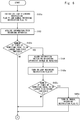
- Figs. 2 , 3 , and 4 are flowcharts for describing a flow of a video image recording control method according to the first embodiment.
- the video image recording control apparatus 1 initializes the loop recording restriction flag (S101). Specifically, the recording controller 13 of the video image recording control apparatus 1 turns off the loop recording restriction flag. Next, the recording controller 13 acquires information on the number of times of data rewriting from the recording apparatus 3 (S102).
- the recording controller 13 determines whether the number of times of data rewriting is equal to or larger than the first threshold ⁇ (S103). When the number of times of data rewriting is smaller than the first threshold ⁇ , the process goes to Step S106. When the number of times of data rewriting is equal to or larger than the first threshold ⁇ , the recording controller 13 instructs the alarm output unit 14 to output alarm information. Then the alarm output unit 14 causes the monitor and the speaker 4 to output alarm information indicating that the recording apparatus 3 should be replaced by another one in accordance with an instruction (S104). Further, the recording controller 13 turns on the loop recording restriction flag (S105). The order of Steps S104 and S105 may be switched or these steps may be performed at the same time.
- the video image data acquisition unit 11 acquires the video image data captured by the camera, which is one example of the image pickup apparatus 2 (S106). Then, the video image recording processing unit 124 of the recording processing unit 12 determines whether the loop recording restriction flag has been turned on (S107). When the loop recording restriction flag is in the ON state, the alarm output unit 14 causes the monitor and the speaker 4 to output information indicating that the recording is being restricted (S109). On the other hand, when the loop recording restriction flag is in the OFF state, the video image recording processing unit 124 starts loop recording of the video image data for the recording apparatus 3 (S108). Then the video image recording processing unit 124 starts the recording in the internal memory 123 (S10).
- the video image recording processing unit 124 may also record detailed information indicating the state or the like of the vehicle in the internal memory 123.
- the video image recording processing unit 124 performs loop recording also for the internal memory 123. Therefore, when a certain period of time passes, the content recorded in the recording apparatus 3 and the internal memory 123 is overwritten by new recording information.
- the abnormality determination unit 122 determines whether an abnormality has occurred (S111).
- the video image recording processing unit 124 copies the content recorded in the internal memory 123 in the recording apparatus 3 (S112). Specifically, the video image recording processing unit 124 records the recording information recorded in the internal memory 123 in the recording apparatus 3 as the event recording mode separately from the loop recording. Further, the internal memory 123 may not be provided, and the video image data may be directly recorded in the recording apparatus 3.
- the video image recording control apparatus 1 determines whether the driving has been ended (S113). During the driving, that is, when the vehicle is still driving, the process goes back to Step S111. On the other hand, when the driving has been ended, this processing is ended.
- the loop recording is normally performed, and video images continue to be recorded during the driving. Therefore, the number of overwriting times, that is, the number of times of data rewriting, in the SD card, which is one example of the recording apparatus 3 becomes inevitably large, and the period until the life of the SD card becomes shorter as compared to use in other applications. Therefore, the user often does not recognize that the SD card has reached the end of its life.
- a warning is given to the user by means of voice, screen display, buzzer or the like, and the loop recording mode is restricted.
- the loop recording is relatively less important than the event recording, and the amount of data written into the SD card and the number of rewriting times are large. Therefore, by restricting the loop recording mode, the rewriting itself is prevented and only the event recording, which is more important than the loop recording, is permitted. It is therefore possible to prolong the life of the SD card while maintaining the function of the drive recorder during a period from the timing when the warning is given to the timing when the SD card is replaced by another one.
- That the end of the life of the SD card or the like is approaching may be detected by the determination based on the number of rewriting times or by known art such as the life information calculation method disclosed in Japanese Unexamined Patent Application Publication No. 2008-9755 . Therefore, detailed descriptions thereof will be omitted.
- a second embodiment is a modified example of the aforementioned first embodiment. That is, in the second embodiment, recording at the time of abnormality, which is recording performed when sensors have detected an abnormal behavior of the vehicle, is recorded as event recording.
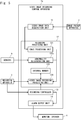
- Fig. 5 is a block diagram showing a configuration of a video image recording control apparatus 1a according to the second embodiment.
- the video image recording control apparatus 1a is different from the video image recording control apparatus 1 in that sensors 5 are further connected thereto.
- the sensors 5 detect abnormal behavior of the vehicle and is, for example, an acceleration sensor or a radar.
- the sensors 5 detect, for example, a contact, an impact or the like of an obstacle.
- the sensors 5 may detect an abnormal sound by a sound-collecting microphone.
- the sensors 5 may acquire vehicle information such as a vehicle speed or a steering wheel angle and use the acquired information for the detection and do not depend on the type of the sensors and the processing means as long as it is possible to detect an abnormality of the vehicle behavior such as angular velocity, illuminance, or temperature. Then an abnormality determination unit 122a determines that an abnormality has occurred in accordance with the results of the detection in the sensors 5, and notifies the video image recording processing unit 124 that the abnormality has been detected.
- vehicle information such as a vehicle speed or a steering wheel angle
- an abnormality determination unit 122a determines that an abnormality has occurred in accordance with the results of the detection in the sensors 5, and notifies the video image recording processing unit 124 that the abnormality has been detected.
- the abnormality determination unit 122a may be installed separately from the video image recording control apparatus 1a in such a way that it is connected to the video image recording control apparatus 1a, and may input the result of the determination of the abnormality by the abnormality determination unit 122a to the video image recording control apparatus 1a.
- a third embodiment is a modified example of the aforementioned first or second embodiment. That is, a recording processing unit according to the third embodiment records video image data captured in accordance with a manual operation by a user in the recording apparatus by the first recording mode, the second recording mode, or a third recording mode in which the video image data is recorded separately from the first recording mode and the second recording mode. Then the recording controller according to the third embodiment restricts recording in a manual recording mode, which is the third recording mode, when the number of times of data rewriting has exceeded a second threshold ⁇ , which is different from the first threshold ⁇ .
- the second threshold ⁇ of the number of times of data rewriting is set to be, for example, larger than the first threshold ⁇ .
- the writing of the video image data in the SD card or the like is not restricted.
- the number of times of data rewriting exceeds the first threshold ⁇ but does not exceed the second threshold ⁇ , only the loop recording in which data is automatically recorded during the driving of the vehicle is restricted.
- a third threshold may be set, and writing may be restricted when it is determined that the degree of the abnormality is low even in the event recording, which is the recording mode when an abnormality of the vehicle has been detected.
- the manual recording may be restricted when the number of times of data rewriting has exceeded the first threshold.
- the setting of the threshold and the setting of the recording mode to be restricted are not limited to those stated above, and the second threshold ⁇ of the number of times of data rewriting may be the same as the first threshold ⁇ .
- a warning is preferably given by voice or the like when the user tries to perform recording.
- there may be a control change such as temporarily canceling the writing restriction by some operation such as an operation in which a recording button is kept to be pressed.
- the recording time in the manual recording may be restricted to be short. It is therefore possible to perform fine recording and alarm control.
- Figs. 6 , 7 , and 8 are flowcharts for describing a flow of the video image recording control method according to the third embodiment.
- the video image recording control apparatus 1 initializes a loop recording restriction flag F1 and a manual recording restriction flag F2 (S101a).
- the recording controller 13 acquires information on the number of times of data rewriting from the recording apparatus 3 (S102).
- the recording controller 13 determines whether the number of times of data rewriting is equal to or larger than the first threshold ⁇ (S103a). When the number of times of data rewriting is smaller than the first threshold ⁇ , the process goes to Step S106. Further, when the number of times of data rewriting is equal to or larger than the first threshold ⁇ , the recording controller 13 instructs the alarm output unit 14 to output alarm information. Then the alarm output unit 14 causes the monitor and the speaker 4 to output alarm information indicating that the recording apparatus 3 should be replaced by another one in accordance with an instruction (S104). Further, the recording controller 13 turns on the loop recording restriction flag F1 (S105a). The order of Step S104 and Step S105a may be switched or these steps may be performed at the same time.
- the recording controller 13 determines whether the number of times of data rewriting is equal to or larger than the second threshold ⁇ (S105b). When the number of times of data rewriting is smaller than the second threshold ⁇ , the process goes to Step S106. On the other hand, when the number of times of data rewriting is equal to or larger than the second threshold ⁇ , the recording controller 13 turns on the manual recording restriction flag F2 (S105c).
- the video image data acquisition unit 11 acquires the video image data captured by the camera (S106). Then the video image recording processing unit 124 of the recording processing unit 12 determines whether the loop recording restriction flag F1 is in the ON state (S107a). When the loop recording restriction flag F1 is in the ON state, the alarm output unit 14 causes the monitor and the speaker 4 to output information indicating that recording is restricted (S109). On the other hand, when the loop recording restriction flag F1 is in the OFF state, the video image recording processing unit 124 starts loop recording of the video image data for the recording apparatus 3 (S108). Then the video image recording processing unit 124 starts recording in the internal memory 123 (S110).
- the video image recording control apparatus 1 determines whether a trigger for the manual recording has been detected (S114).
- the video image recording control apparatus 1 detects, for example, whether the user has turned on a manual recording switch (not shown) of the video image recording control apparatus 1.
- the process goes to Step S111.
- the video image recording processing unit 124 determines whether the manual recording prohibition flag F2 is in the ON state (SI15).
- the manual recording restriction flag F2 is in the OFF state
- the video image recording processing unit 124 starts manual recording of the video image data for the recording apparatus 3 (SI16). That is, the video image recording processing unit 124 records the video image data for the recording apparatus 3.
- the alarm output unit 14 causes the monitor and the speaker 4 to output information indicating that recording by the manual recording is being restricted (SI17).
- the abnormality determination unit 122 determines whether an abnormality has occurred (S111).
- the video image recording processing unit 124 copies the content recorded in the internal memory 123 in the recording apparatus 3 (S112). Specifically, the video image recording processing unit 124 records the recording information recorded in the internal memory 123 in the recording apparatus 3 in the overwrite-prohibited mode.
- the video image recording control apparatus 1 determines whether the driving has been ended (S113). During the driving, that is, when the vehicle is travelling, the process goes back to Step S114. On the other hand, when the driving has been ended, this processing is ended.
- Non-transitory computer readable media include any type of tangible storage media.
- Examples of non-transitory computer readable media include magnetic storage media (such as flexible disks, magnetic tapes, hard disk drives, etc.), optical magnetic storage media (e.g., magneto-optical disks), Compact Disc Read Only Memory (CD-ROM), CD-R, CD-R/W, and semiconductor memories (such as mask ROM, Programmable ROM (PROM), Erasable PROM (EPROM), flash ROM, Random Access Memory (RAM), etc.).
- the program(s) may be provided to a computer using any type of transitory computer readable media.
- Examples of transitory computer readable media include electric signals, optical signals, and electromagnetic waves.
- Transitory computer readable media can provide the program to a computer via a wired communication line (e.g., electric wires, and optical fibers) or a wireless communication line.
- the present disclosure is applicable to a driver recorder mounted on a moving body such as a vehicle and has an industrial applicability.
Landscapes
- Engineering & Computer Science (AREA)
- Multimedia (AREA)
- Physics & Mathematics (AREA)
- General Physics & Mathematics (AREA)
- Signal Processing (AREA)
- Theoretical Computer Science (AREA)
- Emergency Management (AREA)
- Business, Economics & Management (AREA)
- General Engineering & Computer Science (AREA)
- Mechanical Engineering (AREA)
- Time Recorders, Dirve Recorders, Access Control (AREA)
- Television Signal Processing For Recording (AREA)
- Traffic Control Systems (AREA)
- Techniques For Improving Reliability Of Storages (AREA)
- Memory System (AREA)
- Closed-Circuit Television Systems (AREA)
- Emergency Alarm Devices (AREA)
Abstract
Description
- The present disclosure relates to a video image recording control apparatus, a video image recording control method, and a video image recording control program.
- A drive recorder that is mounted on a vehicle and mainly records video images in front of the vehicle records video images in two modes, that is, a loop recording mode and an event recording mode. The loop recording mode is a mode for constantly recording video images captured during the driving. The event recording mode is a mode for recording video images captured when an abnormality such as an accident or sudden braking has been detected. Since the event recording is important as information on an accident or an incident, the video images are recorded as overwrite-prohibited data separately from the loop recording. An SD card is often used as a storage element for such recording.
- Patent Literature 1 discloses a drive recorder in which a warning is given to a user by an operation lamp 28 and a buzzer 29 when the number of rewrites in a memory card 9 has reached the upper limit and the user is notified that the number of rewrites in the memory card 9 has reached the upper limit. Further, an image processing apparatus disclosed in
Patent Literature 2 prohibits rewriting when it is determined that a NAND memory has reached the end of its life. -
- [Patent Literature 1] Japanese Unexamined Patent Application Publication No.
2012-53506 - [Patent Literature 2] Japanese Unexamined Patent Application Publication No.
2015-219746 - However, the technique disclosed in Patent Literature 1 is only alarm means, and the SD card ends up being used even after the number of rewrites in the SD card exceeds the rewrite restricted number unless the user replaces the SD card by another one in accordance with the alarm information. When the SD card continues to be used even after the number of rewrites in the SD card exceeds the rewrite restricted number in the SD card, a problem such that an important scene such as an event has not been recorded may occur. On the other hand, when writing is prohibited, that is, recording itself is prohibited when the memory has reached the end of its life like in
Patent Literature 2, the event recording cannot be performed and the drive recorder function cannot be achieved. - This embodiment has been made in view of the aforementioned problems, and aims to provide a video image recording control apparatus, a video image recording control method, and a video image recording control program for appropriately controlling a recording mode when the end of a rewrite life of a recording apparatus has approached.
- A first aspect of this embodiment provides a video image recording control apparatus including: a recording processing unit configured to record video image data in a recording apparatus by a first recording mode in which video image data captured by an image pickup apparatus is recorded and a second recording mode in which video image data captured when an abnormality has been detected is recorded separately from the first recording mode; and a recording controller configured to restrict the first recording mode for the recording processing unit when the number of times of data rewriting for the recording apparatus has exceeded a first threshold.
- A second aspect of this embodiment provides a video image recording control apparatus including: a recording processing unit configured to record video image data in a recording apparatus by a first recording mode in which video image data captured by an image pickup apparatus is recorded and a second recording mode in which video image data captured when an abnormality has been detected is recorded separately from the first recording mode; and a recording controller configured to restrict the first recording mode for the recording processing unit when it is determined that the life of the recording apparatus has exceeded a predetermined value.
- A third aspect of this embodiment provides a video image recording control method in a video image recording control apparatus including: a recording processing unit configured to record video image data in a recording apparatus by a first recording mode in which video image data captured by an image pickup apparatus is recorded and a second recording mode in which video image data captured when an abnormality has been detected is recorded separately from the first recording mode; and a recording controller configured to perform control on the recording processing unit, the method including the steps of: determining whether the number of times of data rewriting for the recording apparatus has exceeded a first threshold; and restricting the first recording mode for the recording processing unit when it is determined that the number of times of data rewriting for the recording apparatus has exceeded the first threshold.
- A fourth aspect of this embodiment provides a video image recording control program for causing a computer including: a recording processing unit configured to record video image data in a recording apparatus by a first recording mode in which video image data captured by an image pickup apparatus is recorded and a second recording mode in which video image data captured when an abnormality has been detected is recorded separately from the first recording mode; and a recording controller configured to perform control on the recording processing unit, to execute the following steps of: determining whether the number of times of data rewriting for the recording apparatus has exceeded a first threshold; and restricting the first recording mode for the recording processing unit when it is determined that the number of times of data rewriting for the recording apparatus has exceeded the first threshold.
- According to this embodiment, it is possible to provide a video image recording control apparatus, a video image recording control method, and a video image recording control program capable of performing important recording by appropriately controlling a recording mode when the end of a rewrite life of a recording apparatus has approached and maintaining the life of the recording apparatus.
-
-
Fig. 1 is a block diagram showing a configuration of a video image recording control apparatus according to a first embodiment; -
Fig. 2 is a flowchart for describing a flow of a video image recording control method according to the first embodiment; -
Fig. 3 is a flowchart for describing a flow of the video image recording control method according to the first embodiment; -
Fig. 4 is a flowchart for describing the flow of the video image recording control method according to the first embodiment; -
Fig. 5 is a block diagram showing a configuration of a video image recording control apparatus according to a second embodiment; -
Fig. 6 is a flowchart for describing a flow of a video image recording control method according to a third embodiment of the present disclosure; -
Fig. 7 is a flowchart for describing a flow of the video image recording control method according to the third embodiment; and -
Fig. 8 is a flowchart for describing a flow of the video image recording control method according to the third embodiment. - In the following description, with reference to the drawings, specific embodiments when the present disclosure is mounted on a vehicle will be explained in detail. Throughout the drawings, the same elements are denoted by the same reference symbols and overlapping descriptions will be omitted as necessary for the sake of clarification of the description.
-
Fig. 1 is a block diagram showing a configuration of a video image recording control apparatus 1 according to a first embodiment. The video image recording control apparatus 1 is connected to animage pickup apparatus 2, arecording apparatus 3, and a monitor and aspeaker 4. The video image recording control apparatus 1 is, for example, a drive recorder mounted on a moving body such as a vehicle. However, the video image recording control apparatus 1 according to this embodiment is not limited to an in-vehicle drive recorder. Theimage pickup apparatus 2 is, for example, an in-vehicle camera or the like that captures images in front of the vehicle and outputs video image data. Therecording apparatus 3, which is an external storage device, is, for example, an SD card, a USB memory, a hard disk, or a semiconductor memory. Therecording apparatus 3 may be embedded in the video image recording control apparatus 1. It is further assumed that therecording apparatus 3 updates the number of times of data rewriting held therein every time the data is rewritten. The monitor and thespeaker 4 are examples of alarm means for outputting alarm information to a driver or the like of the vehicle by means of voice, buzzer, screen display or the like. - The video image recording control apparatus 1 includes a video image
data acquisition unit 11, arecording processing unit 12, arecording controller 13, and analarm output unit 14. The video imagedata acquisition unit 11 takes in a RAW image (Raw image format) output from theimage pickup apparatus 2 as video image data, and outputs the image that has been taken to therecording processing unit 12. - The
recording processing unit 12 records the video image data in aninternal memory 123 or therecording apparatus 3 in such a way that the video image data is distinguished a write destination device, a write area on this device, an overwrite restriction flag, each mode flag or the like according to a plurality of recording modes. The recording modes include, for example, a first recording mode in which the video image data captured by theimage pickup apparatus 2 is recorded while it is overwritten, a second recording mode in which video image data captured when an abnormality such as an accident or a sudden brake has been detected is recorded in a rewrite prohibited mode, and a third recording mode in which the user manually starts recording. One example of the first recording mode is, for example, a loop recording mode in which video images are automatically recorded during the driving of the vehicle, one example of the second recording mode is an event recording mode, and one example of the third recording mode is a manual recording mode. Further, the manual recording mode may be referred to as the first recording mode and the event recording mode may be referred to as the second recording mode. Further, the event recording mode may be divided into a plurality of modes in accordance with the degree of the abnormality, and one of the modes may be referred to as the first recording mode and another one of them may be referred to as the second recording mode. - The
recording processing unit 12 includes animage processing unit 121, anabnormality determination unit 122, theinternal memory 123, and a video imagerecording processing unit 124. Theimage processing unit 121 performs image processing such as Auto Gain Control (AGC) or white balance adjustment on the image taken by the video imagedata acquisition unit 11, and performs processing such as Moving Picture Experts Group (MPEG) encoding, which is a recording format. Theabnormality determination unit 122 performs processing such as motion detection, motion vector detection, or proximity object detection from the image data output from theimage processing unit 121, detects proximity to an obstacle such as another vehicle, a pedestrian, or a utility pole, and determines, when there is a possibility that a contact or an accident may occur, that an abnormality has occurred. Theabnormality determination unit 122 may determine an abnormality by detecting abnormal brightness of an image or the like and it does not depend on the processing means as long as it can detect an abnormality that can be determined from the image. The image data may be data before MPEG encoding. The video imagerecording processing unit 124 performs processing for recording the image data output from theimage processing unit 121 in theinternal memory 123 or therecording apparatus 3. The video imagerecording processing unit 124 performs recording in accordance with the recording mode and the flag for restricting specific recording described above. When, for example, a loop recording prohibition flag is in the ON state, the video imagerecording processing unit 124 does not perform loop recording. When a loop recording suppression flag is in the ON state, recording in which the bit rate, the resolution, the frame rate, or the data compression rate of the video images is, for example, controlled, and thus the amount of data to be recorded is reduced is performed. In the following processing, the loop recording prohibition flag and the loop recording suppression flag are collectively referred to as a loop recording restriction flag. - The
recording controller 13 acquires the number of times of data rewriting from therecording apparatus 3, and outputs the flag for restricting specific recording when the end of the life of therecording apparatus 3 is approaching. That is, therecording controller 13 performs control for therecording processing unit 12 so as to prohibit the first recording mode or prevent data recording when the number of times of data rewriting for therecording apparatus 3 exceeds a first threshold α. Specifically, therecording controller 13 sets the loop recording restriction flag to the ON state and outputs this flag to the video imagerecording processing unit 124. It is assumed that the first threshold α is smaller than the restriction value of the number of times of data rewriting of therecording apparatus 3. Along with this operation, when the number of times of data rewriting for therecording apparatus 3 exceeds the first threshold α, therecording controller 13 instructs thealarm output unit 14 to output alarm information. For example, therecording controller 13 may set the loop recording restriction flag to the ON state and output this flag to thealarm output unit 14 as well. - The
alarm output unit 14 outputs alarm information to an external device when the number of times of data rewriting for therecording apparatus 3 has exceeded the first threshold α. Thealarm output unit 14 outputs, for example, alarm information for urging replacement of therecording apparatus 3 or alarm information indicating that the recording has been restricted to the monitor and thespeaker 4 in accordance with an instruction from therecording controller 13. Thealarm output unit 14 may output predetermined alarm information when the loop recording restriction flag is in the ON state. Further, the alarm output may be any one of sound, screen display and the like. - Incidentally, the video image recording control apparatus 1 can be achieved by a versatile computer apparatus. In this case, the video image recording control apparatus 1 includes a controller such as a Central Processing Unit (CPU) as a structure that is not shown. Further, a built-in storage unit, which is a component that is not shown, stores a video image recording control program or the like, which is a computer program in which the processing according to this embodiment is implemented, as a component that is not shown. Then the controller reads the video image recording control program or the like stored in the storage unit and executes this program. Accordingly, the video image recording control apparatus 1 operates as the video image
data acquisition unit 11, therecording processing unit 12, therecording controller 13, thealarm output unit 14 and the like. -
Figs. 2 ,3 , and4 are flowcharts for describing a flow of a video image recording control method according to the first embodiment. First, the video image recording control apparatus 1 initializes the loop recording restriction flag (S101). Specifically, therecording controller 13 of the video image recording control apparatus 1 turns off the loop recording restriction flag. Next, therecording controller 13 acquires information on the number of times of data rewriting from the recording apparatus 3 (S102). - Next, the
recording controller 13 determines whether the number of times of data rewriting is equal to or larger than the first threshold α (S103). When the number of times of data rewriting is smaller than the first threshold α, the process goes to Step S106. When the number of times of data rewriting is equal to or larger than the first threshold α, therecording controller 13 instructs thealarm output unit 14 to output alarm information. Then thealarm output unit 14 causes the monitor and thespeaker 4 to output alarm information indicating that therecording apparatus 3 should be replaced by another one in accordance with an instruction (S104). Further, therecording controller 13 turns on the loop recording restriction flag (S105). The order of Steps S104 and S105 may be switched or these steps may be performed at the same time. - After that, the video image
data acquisition unit 11 acquires the video image data captured by the camera, which is one example of the image pickup apparatus 2 (S106). Then, the video imagerecording processing unit 124 of therecording processing unit 12 determines whether the loop recording restriction flag has been turned on (S107). When the loop recording restriction flag is in the ON state, thealarm output unit 14 causes the monitor and thespeaker 4 to output information indicating that the recording is being restricted (S109). On the other hand, when the loop recording restriction flag is in the OFF state, the video imagerecording processing unit 124 starts loop recording of the video image data for the recording apparatus 3 (S108). Then the video imagerecording processing unit 124 starts the recording in the internal memory 123 (S10). The video imagerecording processing unit 124 may also record detailed information indicating the state or the like of the vehicle in theinternal memory 123. The video imagerecording processing unit 124 performs loop recording also for theinternal memory 123. Therefore, when a certain period of time passes, the content recorded in therecording apparatus 3 and theinternal memory 123 is overwritten by new recording information. - After that, the
abnormality determination unit 122 determines whether an abnormality has occurred (S111). When it is determined that an abnormality has occurred, the video imagerecording processing unit 124 copies the content recorded in theinternal memory 123 in the recording apparatus 3 (S112). Specifically, the video imagerecording processing unit 124 records the recording information recorded in theinternal memory 123 in therecording apparatus 3 as the event recording mode separately from the loop recording. Further, theinternal memory 123 may not be provided, and the video image data may be directly recorded in therecording apparatus 3. - Then the video image recording control apparatus 1 determines whether the driving has been ended (S113). During the driving, that is, when the vehicle is still driving, the process goes back to Step S111. On the other hand, when the driving has been ended, this processing is ended.
- In the drive recorder, the loop recording is normally performed, and video images continue to be recorded during the driving. Therefore, the number of overwriting times, that is, the number of times of data rewriting, in the SD card, which is one example of the
recording apparatus 3 becomes inevitably large, and the period until the life of the SD card becomes shorter as compared to use in other applications. Therefore, the user often does not recognize that the SD card has reached the end of its life. - In this embodiment, it is detected that the end of the life of the SD card or the like is approaching, a warning is given to the user by means of voice, screen display, buzzer or the like, and the loop recording mode is restricted. The loop recording is relatively less important than the event recording, and the amount of data written into the SD card and the number of rewriting times are large. Therefore, by restricting the loop recording mode, the rewriting itself is prevented and only the event recording, which is more important than the loop recording, is permitted. It is therefore possible to prolong the life of the SD card while maintaining the function of the drive recorder during a period from the timing when the warning is given to the timing when the SD card is replaced by another one. That the end of the life of the SD card or the like is approaching may be detected by the determination based on the number of rewriting times or by known art such as the life information calculation method disclosed in Japanese Unexamined Patent Application Publication No.
2008-9755 - A second embodiment is a modified example of the aforementioned first embodiment. That is, in the second embodiment, recording at the time of abnormality, which is recording performed when sensors have detected an abnormal behavior of the vehicle, is recorded as event recording.
-
Fig. 5 is a block diagram showing a configuration of a video imagerecording control apparatus 1a according to the second embodiment. The video imagerecording control apparatus 1a is different from the video image recording control apparatus 1 in thatsensors 5 are further connected thereto. Thesensors 5 detect abnormal behavior of the vehicle and is, for example, an acceleration sensor or a radar. Thesensors 5 detect, for example, a contact, an impact or the like of an obstacle. Alternatively, thesensors 5 may detect an abnormal sound by a sound-collecting microphone. Further, thesensors 5 may acquire vehicle information such as a vehicle speed or a steering wheel angle and use the acquired information for the detection and do not depend on the type of the sensors and the processing means as long as it is possible to detect an abnormality of the vehicle behavior such as angular velocity, illuminance, or temperature. Then anabnormality determination unit 122a determines that an abnormality has occurred in accordance with the results of the detection in thesensors 5, and notifies the video imagerecording processing unit 124 that the abnormality has been detected. Theabnormality determination unit 122a may be installed separately from the video imagerecording control apparatus 1a in such a way that it is connected to the video imagerecording control apparatus 1a, and may input the result of the determination of the abnormality by theabnormality determination unit 122a to the video imagerecording control apparatus 1a. - A third embodiment is a modified example of the aforementioned first or second embodiment. That is, a recording processing unit according to the third embodiment records video image data captured in accordance with a manual operation by a user in the recording apparatus by the first recording mode, the second recording mode, or a third recording mode in which the video image data is recorded separately from the first recording mode and the second recording mode. Then the recording controller according to the third embodiment restricts recording in a manual recording mode, which is the third recording mode, when the number of times of data rewriting has exceeded a second threshold β, which is different from the first threshold α.
- The second threshold β of the number of times of data rewriting is set to be, for example, larger than the first threshold α. When the number of times of data rewriting does not exceed the first threshold α, the writing of the video image data in the SD card or the like is not restricted. However, when the number of times of data rewriting exceeds the first threshold α but does not exceed the second threshold β, only the loop recording in which data is automatically recorded during the driving of the vehicle is restricted. When the number of times of data rewriting exceeds the second threshold β, both the loop recording, and the manual recording, which is the recording performed manually by the user, are restricted. Further, a third threshold may be set, and writing may be restricted when it is determined that the degree of the abnormality is low even in the event recording, which is the recording mode when an abnormality of the vehicle has been detected. The manual recording may be restricted when the number of times of data rewriting has exceeded the first threshold. The setting of the threshold and the setting of the recording mode to be restricted are not limited to those stated above, and the second threshold β of the number of times of data rewriting may be the same as the first threshold α. Further, when the manual recording is restricted, a warning is preferably given by voice or the like when the user tries to perform recording. Further, there may be a control change such as temporarily canceling the writing restriction by some operation such as an operation in which a recording button is kept to be pressed. The recording time in the manual recording may be restricted to be short. It is therefore possible to perform fine recording and alarm control.
-
Figs. 6 ,7 , and8 are flowcharts for describing a flow of the video image recording control method according to the third embodiment. First, the video image recording control apparatus 1 initializes a loop recording restriction flag F1 and a manual recording restriction flag F2 (S101a). Next, therecording controller 13 acquires information on the number of times of data rewriting from the recording apparatus 3 (S102). - Next, the
recording controller 13 determines whether the number of times of data rewriting is equal to or larger than the first threshold α (S103a). When the number of times of data rewriting is smaller than the first threshold α, the process goes to Step S106. Further, when the number of times of data rewriting is equal to or larger than the first threshold α, therecording controller 13 instructs thealarm output unit 14 to output alarm information. Then thealarm output unit 14 causes the monitor and thespeaker 4 to output alarm information indicating that therecording apparatus 3 should be replaced by another one in accordance with an instruction (S104). Further, therecording controller 13 turns on the loop recording restriction flag F1 (S105a). The order of Step S104 and Step S105a may be switched or these steps may be performed at the same time. - The
recording controller 13 determines whether the number of times of data rewriting is equal to or larger than the second threshold β (S105b). When the number of times of data rewriting is smaller than the second threshold β, the process goes to Step S106. On the other hand, when the number of times of data rewriting is equal to or larger than the second threshold β, therecording controller 13 turns on the manual recording restriction flag F2 (S105c). - After that, the video image
data acquisition unit 11 acquires the video image data captured by the camera (S106). Then the video imagerecording processing unit 124 of therecording processing unit 12 determines whether the loop recording restriction flag F1 is in the ON state (S107a). When the loop recording restriction flag F1 is in the ON state, thealarm output unit 14 causes the monitor and thespeaker 4 to output information indicating that recording is restricted (S109). On the other hand, when the loop recording restriction flag F1 is in the OFF state, the video imagerecording processing unit 124 starts loop recording of the video image data for the recording apparatus 3 (S108). Then the video imagerecording processing unit 124 starts recording in the internal memory 123 (S110). - After that, the video image recording control apparatus 1 determines whether a trigger for the manual recording has been detected (S114). The video image recording control apparatus 1 detects, for example, whether the user has turned on a manual recording switch (not shown) of the video image recording control apparatus 1. When a trigger for the manual recording has not been detected, the process goes to Step S111. On the other hand, when a trigger for the manual recording has been detected, the video image
recording processing unit 124 determines whether the manual recording prohibition flag F2 is in the ON state (SI15). When the manual recording restriction flag F2 is in the OFF state, the video imagerecording processing unit 124 starts manual recording of the video image data for the recording apparatus 3 (SI16). That is, the video imagerecording processing unit 124 records the video image data for therecording apparatus 3. On the other hand, when the manual recording restriction flag F2 is in the ON state, thealarm output unit 14 causes the monitor and thespeaker 4 to output information indicating that recording by the manual recording is being restricted (SI17). - After that, the
abnormality determination unit 122 determines whether an abnormality has occurred (S111). When it is determined that an abnormality has occurred, the video imagerecording processing unit 124 copies the content recorded in theinternal memory 123 in the recording apparatus 3 (S112). Specifically, the video imagerecording processing unit 124 records the recording information recorded in theinternal memory 123 in therecording apparatus 3 in the overwrite-prohibited mode. - Then the video image recording control apparatus 1 determines whether the driving has been ended (S113). During the driving, that is, when the vehicle is travelling, the process goes back to Step S114. On the other hand, when the driving has been ended, this processing is ended.
- While the present disclosure has been described in view of the aforementioned embodiments, it is needless to say that the present disclosure is not limited to the configuration of the aforementioned embodiments and may include various modifications, corrections, and combinations that those skilled in the art would have made within the scope set forth in the claims according to the present application.
- Further, arbitrary processing of the aforementioned video image recording control apparatus can be achieved by causing a CPU to execute a computer program. In this case, the computer program can be stored and provided to a computer using any type of non-transitory computer readable media. Non-transitory computer readable media include any type of tangible storage media. Examples of non-transitory computer readable media include magnetic storage media (such as flexible disks, magnetic tapes, hard disk drives, etc.), optical magnetic storage media (e.g., magneto-optical disks), Compact Disc Read Only Memory (CD-ROM), CD-R, CD-R/W, and semiconductor memories (such as mask ROM, Programmable ROM (PROM), Erasable PROM (EPROM), flash ROM, Random Access Memory (RAM), etc.). The program(s) may be provided to a computer using any type of transitory computer readable media. Examples of transitory computer readable media include electric signals, optical signals, and electromagnetic waves. Transitory computer readable media can provide the program to a computer via a wired communication line (e.g., electric wires, and optical fibers) or a wireless communication line.
- Further, besides a case in which the functions of the aforementioned embodiments are achieved by a computer executing a program that achieves the functions of the aforementioned embodiments, a case in which the functions of the aforementioned embodiments are achieved by this program cooperating with an Operating System (OS) or an application software operating on the computer is also included in the embodiments of the present disclosure. Further, a case in which some or all of the processing of this program is performed by a function expansion board inserted into the computer or a function expansion unit connected to the computer and thus the functions of the aforementioned embodiments are achieved is also included in the embodiments of the present disclosure.
- This application is based upon and claims the benefit of priority from Japanese Patent Application No.
2017-012937, filed on January 27, 2017 - The present disclosure is applicable to a driver recorder mounted on a moving body such as a vehicle and has an industrial applicability.
-
- 1
- VIDEO IMAGE RECORDING CONTROL APPARATUS
- 1A
- VIDEO IMAGE RECORDING CONTROL APPARATUS
- 11
- VIDEO IMAGE DATA ACQUISITION UNIT
- 12
- RECORDING PROCESSING UNIT
- 121
- IMAGE PROCESSING UNIT
- 122
- ABNORMALITY DETERMINATION UNIT
- 122a
- ABNORMALITY DETERMINATION UNIT
- 123
- INTERNAL MEMORY
- 124
- VIDEO IMAGE RECORDING PROCESSING UNIT
- 13
- RECORDING CONTROLLER
- 14
- ALARM OUTPUT UNIT
- 2
- IMAGE PICKUP APPARATUS
- 3
- RECORDING APPARATUS
- 4
- MONITOR AND SPEAKER
- 5
- SENSORS
Claims (6)
- A video image recording control apparatus comprising:a recording processing unit configured to record video image data in a recording apparatus by a first recording mode in which video image data captured by an image pickup apparatus is recorded and a second recording mode in which video image data captured when an abnormality has been detected is recorded separately from the first recording mode; anda recording controller configured to restrict the first recording mode for the recording processing unit when the number of times of data rewriting for the recording apparatus has exceeded a first threshold.
- The video image recording control apparatus according to Claim 1, wherein
the recording processing unit records video image data captured in accordance with a manual operation by a user in the recording apparatus by a third recording mode in which the video image data is recorded separately from the first recording mode, the second recording mode, or both of the first recording mode and the second recording mode, and
the recording controller restricts the third recording mode when the number of times of data rewriting exceeds a second threshold, which is different from the first threshold. - The video image recording control apparatus according to Claim 1 or 2, further comprising an alarm output unit configured to output alarm information to an external device when the number of times of data rewriting for the recording apparatus has exceeded the first threshold or the second threshold.
- A video image recording control apparatus comprising:a recording processing unit configured to record video image data in a recording apparatus by a first recording mode in which video image data captured by an image pickup apparatus is recorded and a second recording mode in which video image data captured when an abnormality has been detected is recorded separately from the first recording mode; anda recording controller configured to restrict the first recording mode for the recording processing unit when it is determined that the life of the recording apparatus has exceeded a predetermined value.
- A video image recording control method in a video image recording control apparatus comprising:a recording processing unit configured to record video image data in a recording apparatus by a first recording mode in which video image data captured by an image pickup apparatus is recorded and a second recording mode in which video image data captured when an abnormality has been detected is recorded separately from the first recording mode; anda recording controller configured to perform control on the recording processing unit, the method comprising the steps of:determining whether the number of times of data rewriting for the recording apparatus has exceeded a first threshold; andrestricting the first recording mode for the recording processing unit when it is determined that the number of times of data rewriting for the recording apparatus has exceeded the first threshold.
- A video image recording control program for causing a computer comprising:a recording processing unit configured to record video image data in a recording apparatus by a first recording mode in which video image data captured by an image pickup apparatus is recorded and a second recording mode in which video image data captured when an abnormality has been detected is recorded separately from the first recording mode; anda recording controller configured to perform control on the recording processing unit, to execute the following steps of:determining whether the number of times of data rewriting for the recording apparatus has exceeded a first threshold; andrestricting the first recording mode for the recording processing unit when it is determined that the number of times of data rewriting for the recording apparatus has exceeded the first threshold.
Applications Claiming Priority (2)
| Application Number | Priority Date | Filing Date | Title |
|---|---|---|---|
| JP2017012937A JP6750518B2 (en) | 2017-01-27 | 2017-01-27 | Video recording control device, method and program |
| PCT/JP2017/043449 WO2018139057A1 (en) | 2017-01-27 | 2017-12-04 | Video recording control device, method and program |
Publications (3)
| Publication Number | Publication Date |
|---|---|
| EP3576405A1 true EP3576405A1 (en) | 2019-12-04 |
| EP3576405A4 EP3576405A4 (en) | 2020-01-15 |
| EP3576405B1 EP3576405B1 (en) | 2024-06-26 |
Family
ID=62979196
Family Applications (1)
| Application Number | Title | Priority Date | Filing Date |
|---|---|---|---|
| EP17894107.6A Active EP3576405B1 (en) | 2017-01-27 | 2017-12-04 | Video recording control device, method and program |
Country Status (4)
| Country | Link |
|---|---|
| US (1) | US10573343B2 (en) |
| EP (1) | EP3576405B1 (en) |
| JP (1) | JP6750518B2 (en) |
| WO (1) | WO2018139057A1 (en) |
Cited By (1)
| Publication number | Priority date | Publication date | Assignee | Title |
|---|---|---|---|---|
| CN110675528A (en) * | 2019-09-30 | 2020-01-10 | 重庆元韩汽车技术设计研究院有限公司 | Intelligent driving image recording system and method for intelligent driving |
Families Citing this family (5)
| Publication number | Priority date | Publication date | Assignee | Title |
|---|---|---|---|---|
| CN111630574B (en) * | 2018-11-29 | 2022-12-20 | Jvc建伍株式会社 | Recording device, recording method and storage medium |
| JP7368092B2 (en) * | 2019-03-19 | 2023-10-24 | パナソニックホールディングス株式会社 | Accident detection device and accident detection method |
| JPWO2020235641A1 (en) * | 2019-05-21 | 2020-11-26 | ||
| US11120675B2 (en) * | 2019-07-24 | 2021-09-14 | Pix Art Imaging Inc. | Smart motion detection device |
| JP7848671B2 (en) * | 2022-12-01 | 2026-04-21 | トヨタ自動車株式会社 | Vehicle information management device, information management program, and information management method |
Family Cites Families (12)
| Publication number | Priority date | Publication date | Assignee | Title |
|---|---|---|---|---|
| KR20040012642A (en) * | 2003-12-22 | 2004-02-11 | 삼성전자주식회사 | Apparatus and method for detecting an abnormality in a recorded signal |
| JP4215746B2 (en) * | 2005-05-20 | 2009-01-28 | Necインフロンティア株式会社 | Information processing apparatus and life monitoring method |
| JP4645538B2 (en) | 2006-06-29 | 2011-03-09 | ソニー株式会社 | Recording apparatus and life information calculation method |
| JP2009289204A (en) * | 2008-05-30 | 2009-12-10 | Toyota Motor Corp | In-vehicle data recording system and in-vehicle data recording method |
| JP2012053506A (en) * | 2010-08-31 | 2012-03-15 | Fujitsu Ten Ltd | Drive recorder and limit notification method |
| JP5695523B2 (en) * | 2011-08-12 | 2015-04-08 | 川崎重工業株式会社 | Vehicle information acquisition system |
| JP5961376B2 (en) * | 2011-12-20 | 2016-08-02 | Kyb株式会社 | Data recording apparatus and drive recorder |
| JP6006943B2 (en) * | 2012-01-27 | 2016-10-12 | 矢崎エナジーシステム株式会社 | Data recording device |
| JP6355234B2 (en) * | 2013-04-09 | 2018-07-11 | 株式会社ユピテル | Image recording apparatus, image recording system, and program |
| JP6167067B2 (en) | 2014-05-19 | 2017-07-19 | 京セラドキュメントソリューションズ株式会社 | Data storage device and image processing device |
| JP6499514B2 (en) * | 2015-05-29 | 2019-04-10 | 株式会社デンソーテン | Drive recorder, data recording system, data recording method, and program |
| JP6346926B2 (en) | 2016-10-27 | 2018-06-20 | 株式会社ニューギン | Game machine |
-
2017
- 2017-01-27 JP JP2017012937A patent/JP6750518B2/en active Active
- 2017-12-04 WO PCT/JP2017/043449 patent/WO2018139057A1/en not_active Ceased
- 2017-12-04 EP EP17894107.6A patent/EP3576405B1/en active Active
-
2019
- 2019-04-03 US US16/374,041 patent/US10573343B2/en active Active
Cited By (1)
| Publication number | Priority date | Publication date | Assignee | Title |
|---|---|---|---|---|
| CN110675528A (en) * | 2019-09-30 | 2020-01-10 | 重庆元韩汽车技术设计研究院有限公司 | Intelligent driving image recording system and method for intelligent driving |
Also Published As
| Publication number | Publication date |
|---|---|
| EP3576405A4 (en) | 2020-01-15 |
| JP2018121279A (en) | 2018-08-02 |
| US10573343B2 (en) | 2020-02-25 |
| JP6750518B2 (en) | 2020-09-02 |
| EP3576405B1 (en) | 2024-06-26 |
| US20190228803A1 (en) | 2019-07-25 |
| WO2018139057A1 (en) | 2018-08-02 |
Similar Documents
| Publication | Publication Date | Title |
|---|---|---|
| EP3576405B1 (en) | Video recording control device, method and program | |
| JP4661734B2 (en) | In-vehicle warning system | |
| US10964348B2 (en) | Recording control apparatus, recording apparatus, recording control method, and recording control program | |
| US10739367B2 (en) | On-vehicle image recording apparatus, on-vehicle image recording method, and on-vehicle image recording program | |
| WO2021059924A1 (en) | Recording control device, recording control method, and recording control program | |
| JP6476423B2 (en) | Recording apparatus and program | |
| US20200043260A1 (en) | Recording control device, recording apparatus, navigation apparatus, recording method, and non-transitory computer readable medium | |
| JP6962712B2 (en) | In-vehicle image recording device | |
| JP6981319B2 (en) | Recording control device, recording control method, and recording control program | |
| JP7831565B2 (en) | Recording device, recording method, and program | |
| WO2019087664A1 (en) | Recording device for vehicle, event information recording method, and program | |
| JP6059969B2 (en) | Drive recorder | |
| JP5961376B2 (en) | Data recording apparatus and drive recorder | |
| WO2020144949A1 (en) | Recording control device, recording control system, recording control method, and program | |
| JP7487460B2 (en) | Driving assistance device, driving assistance method, and driving assistance program | |
| US11495066B2 (en) | Recording device for vehicles, recording method for vehicles, and a non-transitory computer readable medium | |
| JP7295675B2 (en) | Video recording device and video recording method | |
| CN111684498B (en) | Vehicle imaging recording device, vehicle imaging control method, and recording medium | |
| JP7494474B2 (en) | Recording control device, recording control method, and program | |
| WO2021131129A1 (en) | Recording device, recording method, and program | |
| JP7424040B2 (en) | Recording device, recording method and program | |
| JP2021100208A (en) | Recording device, recording method, and program | |
| KR20110021411A (en) | Vehicle image storage device and its image quality improvement method |
Legal Events
| Date | Code | Title | Description |
|---|---|---|---|
| STAA | Information on the status of an ep patent application or granted ep patent |
Free format text: STATUS: THE INTERNATIONAL PUBLICATION HAS BEEN MADE |
|
| PUAI | Public reference made under article 153(3) epc to a published international application that has entered the european phase |
Free format text: ORIGINAL CODE: 0009012 |
|
| STAA | Information on the status of an ep patent application or granted ep patent |
Free format text: STATUS: REQUEST FOR EXAMINATION WAS MADE |
|
| 17P | Request for examination filed |
Effective date: 20190612 |
|
| AK | Designated contracting states |
Kind code of ref document: A1 Designated state(s): AL AT BE BG CH CY CZ DE DK EE ES FI FR GB GR HR HU IE IS IT LI LT LU LV MC MK MT NL NO PL PT RO RS SE SI SK SM TR |
|
| AX | Request for extension of the european patent |
Extension state: BA ME |
|
| A4 | Supplementary search report drawn up and despatched |
Effective date: 20191216 |
|
| RIC1 | Information provided on ipc code assigned before grant |
Ipc: H04N 5/907 20060101ALI20191206BHEP Ipc: G07C 5/00 20060101ALI20191206BHEP Ipc: B60Q 1/00 20060101ALI20191206BHEP Ipc: G08B 21/00 20060101ALI20191206BHEP Ipc: H04N 7/18 20060101ALI20191206BHEP Ipc: G06F 12/16 20060101ALI20191206BHEP Ipc: H04N 5/77 20060101AFI20191206BHEP Ipc: G08G 1/00 20060101ALI20191206BHEP Ipc: H04N 5/76 20060101ALI20191206BHEP Ipc: G07C 5/08 20060101ALI20191206BHEP |
|
| DAV | Request for validation of the european patent (deleted) | ||
| DAX | Request for extension of the european patent (deleted) | ||
| STAA | Information on the status of an ep patent application or granted ep patent |
Free format text: STATUS: EXAMINATION IS IN PROGRESS |
|
| 17Q | First examination report despatched |
Effective date: 20210316 |
|
| RIC1 | Information provided on ipc code assigned before grant |
Ipc: G07C 5/08 20060101ALI20211223BHEP Ipc: H04N 7/18 20060101ALI20211223BHEP Ipc: H04N 5/907 20060101ALI20211223BHEP Ipc: H04N 5/77 20060101ALI20211223BHEP Ipc: H04N 5/76 20060101ALI20211223BHEP Ipc: B60Q 9/00 20060101AFI20211223BHEP |
|
| REG | Reference to a national code |
Ref legal event code: R079 Free format text: PREVIOUS MAIN CLASS: H04N0005770000 Ipc: H04N0005760000 Ref country code: DE Ref legal event code: R079 Ref document number: 602017082895 Country of ref document: DE Free format text: PREVIOUS MAIN CLASS: H04N0005770000 Ipc: H04N0005760000 |
|
| GRAP | Despatch of communication of intention to grant a patent |
Free format text: ORIGINAL CODE: EPIDOSNIGR1 |
|
| STAA | Information on the status of an ep patent application or granted ep patent |
Free format text: STATUS: GRANT OF PATENT IS INTENDED |
|
| RIC1 | Information provided on ipc code assigned before grant |
Ipc: B60Q 9/00 20060101ALN20240129BHEP Ipc: H04N 7/18 20060101ALN20240129BHEP Ipc: H04N 5/77 20060101ALN20240129BHEP Ipc: G07C 5/08 20060101ALI20240129BHEP Ipc: H04N 5/907 20060101ALI20240129BHEP Ipc: H04N 5/76 20060101AFI20240129BHEP |
|
| INTG | Intention to grant announced |
Effective date: 20240220 |
|
| GRAS | Grant fee paid |
Free format text: ORIGINAL CODE: EPIDOSNIGR3 |
|
| GRAA | (expected) grant |
Free format text: ORIGINAL CODE: 0009210 |
|
| STAA | Information on the status of an ep patent application or granted ep patent |
Free format text: STATUS: THE PATENT HAS BEEN GRANTED |
|
| AK | Designated contracting states |
Kind code of ref document: B1 Designated state(s): AL AT BE BG CH CY CZ DE DK EE ES FI FR GB GR HR HU IE IS IT LI LT LU LV MC MK MT NL NO PL PT RO RS SE SI SK SM TR |
|
| REG | Reference to a national code |
Ref country code: GB Ref legal event code: FG4D |
|
| REG | Reference to a national code |
Ref country code: CH Ref legal event code: EP |
|
| REG | Reference to a national code |
Ref country code: DE Ref legal event code: R096 Ref document number: 602017082895 Country of ref document: DE |
|
| PG25 | Lapsed in a contracting state [announced via postgrant information from national office to epo] |
Ref country code: BG Free format text: LAPSE BECAUSE OF FAILURE TO SUBMIT A TRANSLATION OF THE DESCRIPTION OR TO PAY THE FEE WITHIN THE PRESCRIBED TIME-LIMIT Effective date: 20240626 |
|
| PG25 | Lapsed in a contracting state [announced via postgrant information from national office to epo] |
Ref country code: HR Free format text: LAPSE BECAUSE OF FAILURE TO SUBMIT A TRANSLATION OF THE DESCRIPTION OR TO PAY THE FEE WITHIN THE PRESCRIBED TIME-LIMIT Effective date: 20240626 Ref country code: FI Free format text: LAPSE BECAUSE OF FAILURE TO SUBMIT A TRANSLATION OF THE DESCRIPTION OR TO PAY THE FEE WITHIN THE PRESCRIBED TIME-LIMIT Effective date: 20240626 |
|
| REG | Reference to a national code |
Ref country code: LT Ref legal event code: MG9D |
|
| PG25 | Lapsed in a contracting state [announced via postgrant information from national office to epo] |
Ref country code: GR Free format text: LAPSE BECAUSE OF FAILURE TO SUBMIT A TRANSLATION OF THE DESCRIPTION OR TO PAY THE FEE WITHIN THE PRESCRIBED TIME-LIMIT Effective date: 20240927 |
|
| PG25 | Lapsed in a contracting state [announced via postgrant information from national office to epo] |
Ref country code: LV Free format text: LAPSE BECAUSE OF FAILURE TO SUBMIT A TRANSLATION OF THE DESCRIPTION OR TO PAY THE FEE WITHIN THE PRESCRIBED TIME-LIMIT Effective date: 20240626 |
|
| REG | Reference to a national code |
Ref country code: NL Ref legal event code: MP Effective date: 20240626 |
|
| PG25 | Lapsed in a contracting state [announced via postgrant information from national office to epo] |
Ref country code: NO Free format text: LAPSE BECAUSE OF FAILURE TO SUBMIT A TRANSLATION OF THE DESCRIPTION OR TO PAY THE FEE WITHIN THE PRESCRIBED TIME-LIMIT Effective date: 20240926 Ref country code: LV Free format text: LAPSE BECAUSE OF FAILURE TO SUBMIT A TRANSLATION OF THE DESCRIPTION OR TO PAY THE FEE WITHIN THE PRESCRIBED TIME-LIMIT Effective date: 20240626 Ref country code: HR Free format text: LAPSE BECAUSE OF FAILURE TO SUBMIT A TRANSLATION OF THE DESCRIPTION OR TO PAY THE FEE WITHIN THE PRESCRIBED TIME-LIMIT Effective date: 20240626 Ref country code: GR Free format text: LAPSE BECAUSE OF FAILURE TO SUBMIT A TRANSLATION OF THE DESCRIPTION OR TO PAY THE FEE WITHIN THE PRESCRIBED TIME-LIMIT Effective date: 20240927 Ref country code: FI Free format text: LAPSE BECAUSE OF FAILURE TO SUBMIT A TRANSLATION OF THE DESCRIPTION OR TO PAY THE FEE WITHIN THE PRESCRIBED TIME-LIMIT Effective date: 20240626 Ref country code: BG Free format text: LAPSE BECAUSE OF FAILURE TO SUBMIT A TRANSLATION OF THE DESCRIPTION OR TO PAY THE FEE WITHIN THE PRESCRIBED TIME-LIMIT Effective date: 20240626 Ref country code: RS Free format text: LAPSE BECAUSE OF FAILURE TO SUBMIT A TRANSLATION OF THE DESCRIPTION OR TO PAY THE FEE WITHIN THE PRESCRIBED TIME-LIMIT Effective date: 20240926 |
|
| PG25 | Lapsed in a contracting state [announced via postgrant information from national office to epo] |
Ref country code: NL Free format text: LAPSE BECAUSE OF FAILURE TO SUBMIT A TRANSLATION OF THE DESCRIPTION OR TO PAY THE FEE WITHIN THE PRESCRIBED TIME-LIMIT Effective date: 20240626 |
|
| REG | Reference to a national code |
Ref country code: AT Ref legal event code: MK05 Ref document number: 1698635 Country of ref document: AT Kind code of ref document: T Effective date: 20240626 |
|
| PG25 | Lapsed in a contracting state [announced via postgrant information from national office to epo] |
Ref country code: NL Free format text: LAPSE BECAUSE OF FAILURE TO SUBMIT A TRANSLATION OF THE DESCRIPTION OR TO PAY THE FEE WITHIN THE PRESCRIBED TIME-LIMIT Effective date: 20240626 |
|
| PG25 | Lapsed in a contracting state [announced via postgrant information from national office to epo] |
Ref country code: PT Free format text: LAPSE BECAUSE OF FAILURE TO SUBMIT A TRANSLATION OF THE DESCRIPTION OR TO PAY THE FEE WITHIN THE PRESCRIBED TIME-LIMIT Effective date: 20241028 |
|
| PG25 | Lapsed in a contracting state [announced via postgrant information from national office to epo] |
Ref country code: PT Free format text: LAPSE BECAUSE OF FAILURE TO SUBMIT A TRANSLATION OF THE DESCRIPTION OR TO PAY THE FEE WITHIN THE PRESCRIBED TIME-LIMIT Effective date: 20241028 |
|
| PG25 | Lapsed in a contracting state [announced via postgrant information from national office to epo] |
Ref country code: PL Free format text: LAPSE BECAUSE OF FAILURE TO SUBMIT A TRANSLATION OF THE DESCRIPTION OR TO PAY THE FEE WITHIN THE PRESCRIBED TIME-LIMIT Effective date: 20240626 |
|
| PG25 | Lapsed in a contracting state [announced via postgrant information from national office to epo] |
Ref country code: EE Free format text: LAPSE BECAUSE OF FAILURE TO SUBMIT A TRANSLATION OF THE DESCRIPTION OR TO PAY THE FEE WITHIN THE PRESCRIBED TIME-LIMIT Effective date: 20240626 |
|
| PG25 | Lapsed in a contracting state [announced via postgrant information from national office to epo] |
Ref country code: IS Free format text: LAPSE BECAUSE OF FAILURE TO SUBMIT A TRANSLATION OF THE DESCRIPTION OR TO PAY THE FEE WITHIN THE PRESCRIBED TIME-LIMIT Effective date: 20241026 Ref country code: AT Free format text: LAPSE BECAUSE OF FAILURE TO SUBMIT A TRANSLATION OF THE DESCRIPTION OR TO PAY THE FEE WITHIN THE PRESCRIBED TIME-LIMIT Effective date: 20240626 |
|
| PG25 | Lapsed in a contracting state [announced via postgrant information from national office to epo] |
Ref country code: CZ Free format text: LAPSE BECAUSE OF FAILURE TO SUBMIT A TRANSLATION OF THE DESCRIPTION OR TO PAY THE FEE WITHIN THE PRESCRIBED TIME-LIMIT Effective date: 20240626 |
|
| PG25 | Lapsed in a contracting state [announced via postgrant information from national office to epo] |
Ref country code: RO Free format text: LAPSE BECAUSE OF FAILURE TO SUBMIT A TRANSLATION OF THE DESCRIPTION OR TO PAY THE FEE WITHIN THE PRESCRIBED TIME-LIMIT Effective date: 20240626 Ref country code: SK Free format text: LAPSE BECAUSE OF FAILURE TO SUBMIT A TRANSLATION OF THE DESCRIPTION OR TO PAY THE FEE WITHIN THE PRESCRIBED TIME-LIMIT Effective date: 20240626 |
|
| PG25 | Lapsed in a contracting state [announced via postgrant information from national office to epo] |
Ref country code: SM Free format text: LAPSE BECAUSE OF FAILURE TO SUBMIT A TRANSLATION OF THE DESCRIPTION OR TO PAY THE FEE WITHIN THE PRESCRIBED TIME-LIMIT Effective date: 20240626 Ref country code: ES Free format text: LAPSE BECAUSE OF FAILURE TO SUBMIT A TRANSLATION OF THE DESCRIPTION OR TO PAY THE FEE WITHIN THE PRESCRIBED TIME-LIMIT Effective date: 20240626 |
|
| PG25 | Lapsed in a contracting state [announced via postgrant information from national office to epo] |
Ref country code: SM Free format text: LAPSE BECAUSE OF FAILURE TO SUBMIT A TRANSLATION OF THE DESCRIPTION OR TO PAY THE FEE WITHIN THE PRESCRIBED TIME-LIMIT Effective date: 20240626 Ref country code: SK Free format text: LAPSE BECAUSE OF FAILURE TO SUBMIT A TRANSLATION OF THE DESCRIPTION OR TO PAY THE FEE WITHIN THE PRESCRIBED TIME-LIMIT Effective date: 20240626 Ref country code: RO Free format text: LAPSE BECAUSE OF FAILURE TO SUBMIT A TRANSLATION OF THE DESCRIPTION OR TO PAY THE FEE WITHIN THE PRESCRIBED TIME-LIMIT Effective date: 20240626 Ref country code: PL Free format text: LAPSE BECAUSE OF FAILURE TO SUBMIT A TRANSLATION OF THE DESCRIPTION OR TO PAY THE FEE WITHIN THE PRESCRIBED TIME-LIMIT Effective date: 20240626 Ref country code: IS Free format text: LAPSE BECAUSE OF FAILURE TO SUBMIT A TRANSLATION OF THE DESCRIPTION OR TO PAY THE FEE WITHIN THE PRESCRIBED TIME-LIMIT Effective date: 20241026 Ref country code: ES Free format text: LAPSE BECAUSE OF FAILURE TO SUBMIT A TRANSLATION OF THE DESCRIPTION OR TO PAY THE FEE WITHIN THE PRESCRIBED TIME-LIMIT Effective date: 20240626 Ref country code: EE Free format text: LAPSE BECAUSE OF FAILURE TO SUBMIT A TRANSLATION OF THE DESCRIPTION OR TO PAY THE FEE WITHIN THE PRESCRIBED TIME-LIMIT Effective date: 20240626 Ref country code: CZ Free format text: LAPSE BECAUSE OF FAILURE TO SUBMIT A TRANSLATION OF THE DESCRIPTION OR TO PAY THE FEE WITHIN THE PRESCRIBED TIME-LIMIT Effective date: 20240626 Ref country code: AT Free format text: LAPSE BECAUSE OF FAILURE TO SUBMIT A TRANSLATION OF THE DESCRIPTION OR TO PAY THE FEE WITHIN THE PRESCRIBED TIME-LIMIT Effective date: 20240626 |
|
| PG25 | Lapsed in a contracting state [announced via postgrant information from national office to epo] |
Ref country code: IT Free format text: LAPSE BECAUSE OF FAILURE TO SUBMIT A TRANSLATION OF THE DESCRIPTION OR TO PAY THE FEE WITHIN THE PRESCRIBED TIME-LIMIT Effective date: 20240626 |
|
| REG | Reference to a national code |
Ref country code: DE Ref legal event code: R097 Ref document number: 602017082895 Country of ref document: DE |
|
| PG25 | Lapsed in a contracting state [announced via postgrant information from national office to epo] |
Ref country code: DK Free format text: LAPSE BECAUSE OF FAILURE TO SUBMIT A TRANSLATION OF THE DESCRIPTION OR TO PAY THE FEE WITHIN THE PRESCRIBED TIME-LIMIT Effective date: 20240626 |
|
| PLBE | No opposition filed within time limit |
Free format text: ORIGINAL CODE: 0009261 |
|
| STAA | Information on the status of an ep patent application or granted ep patent |
Free format text: STATUS: NO OPPOSITION FILED WITHIN TIME LIMIT |
|
| 26N | No opposition filed |
Effective date: 20250327 |
|
| PG25 | Lapsed in a contracting state [announced via postgrant information from national office to epo] |
Ref country code: MC Free format text: LAPSE BECAUSE OF FAILURE TO SUBMIT A TRANSLATION OF THE DESCRIPTION OR TO PAY THE FEE WITHIN THE PRESCRIBED TIME-LIMIT Effective date: 20240626 |
|
| REG | Reference to a national code |
Ref country code: CH Ref legal event code: PL |
|
| PG25 | Lapsed in a contracting state [announced via postgrant information from national office to epo] |
Ref country code: LU Free format text: LAPSE BECAUSE OF NON-PAYMENT OF DUE FEES Effective date: 20241204 |
|
| GBPC | Gb: european patent ceased through non-payment of renewal fee |
Effective date: 20241204 |
|
| PG25 | Lapsed in a contracting state [announced via postgrant information from national office to epo] |
Ref country code: SE Free format text: LAPSE BECAUSE OF FAILURE TO SUBMIT A TRANSLATION OF THE DESCRIPTION OR TO PAY THE FEE WITHIN THE PRESCRIBED TIME-LIMIT Effective date: 20240626 |
|
| REG | Reference to a national code |
Ref country code: BE Ref legal event code: MM Effective date: 20241231 |
|
| PG25 | Lapsed in a contracting state [announced via postgrant information from national office to epo] |
Ref country code: GB Free format text: LAPSE BECAUSE OF NON-PAYMENT OF DUE FEES Effective date: 20241204 Ref country code: BE Free format text: LAPSE BECAUSE OF NON-PAYMENT OF DUE FEES Effective date: 20241231 |
|
| PG25 | Lapsed in a contracting state [announced via postgrant information from national office to epo] |
Ref country code: FR Free format text: LAPSE BECAUSE OF NON-PAYMENT OF DUE FEES Effective date: 20241231 |
|
| PG25 | Lapsed in a contracting state [announced via postgrant information from national office to epo] |
Ref country code: CH Free format text: LAPSE BECAUSE OF NON-PAYMENT OF DUE FEES Effective date: 20241231 |
|
| PG25 | Lapsed in a contracting state [announced via postgrant information from national office to epo] |
Ref country code: IE Free format text: LAPSE BECAUSE OF NON-PAYMENT OF DUE FEES Effective date: 20241204 |
|
| PGFP | Annual fee paid to national office [announced via postgrant information from national office to epo] |
Ref country code: DE Payment date: 20251028 Year of fee payment: 9 |
|
| PG25 | Lapsed in a contracting state [announced via postgrant information from national office to epo] |
Ref country code: CY Free format text: LAPSE BECAUSE OF FAILURE TO SUBMIT A TRANSLATION OF THE DESCRIPTION OR TO PAY THE FEE WITHIN THE PRESCRIBED TIME-LIMIT; INVALID AB INITIO Effective date: 20171204 |