EP3576362A1 - Datenübertragungsverfahren und -vorrichtung sowie datenempfangsverfahren und -vorrichtung - Google Patents
Datenübertragungsverfahren und -vorrichtung sowie datenempfangsverfahren und -vorrichtung Download PDFInfo
- Publication number
- EP3576362A1 EP3576362A1 EP18772439.8A EP18772439A EP3576362A1 EP 3576362 A1 EP3576362 A1 EP 3576362A1 EP 18772439 A EP18772439 A EP 18772439A EP 3576362 A1 EP3576362 A1 EP 3576362A1
- Authority
- EP
- European Patent Office
- Prior art keywords
- spatial
- flows
- data
- terminal device
- flow
- Prior art date
- Legal status (The legal status is an assumption and is not a legal conclusion. Google has not performed a legal analysis and makes no representation as to the accuracy of the status listed.)
- Granted
Links
Images

Classifications
-
- H—ELECTRICITY
- H04—ELECTRIC COMMUNICATION TECHNIQUE
- H04L—TRANSMISSION OF DIGITAL INFORMATION, e.g. TELEGRAPHIC COMMUNICATION
- H04L25/00—Baseband systems
- H04L25/02—Details ; arrangements for supplying electrical power along data transmission lines
- H04L25/03—Shaping networks in transmitter or receiver, e.g. adaptive shaping networks
- H04L25/03006—Arrangements for removing intersymbol interference
- H04L25/03343—Arrangements at the transmitter end
-
- H—ELECTRICITY
- H04—ELECTRIC COMMUNICATION TECHNIQUE
- H04B—TRANSMISSION
- H04B7/00—Radio transmission systems, i.e. using radiation field
- H04B7/02—Diversity systems; Multi-antenna system, i.e. transmission or reception using multiple antennas
- H04B7/04—Diversity systems; Multi-antenna system, i.e. transmission or reception using multiple antennas using two or more spaced independent antennas
- H04B7/0413—MIMO systems
- H04B7/0452—Multi-user MIMO systems
-
- H—ELECTRICITY
- H04—ELECTRIC COMMUNICATION TECHNIQUE
- H04B—TRANSMISSION
- H04B7/00—Radio transmission systems, i.e. using radiation field
- H04B7/02—Diversity systems; Multi-antenna system, i.e. transmission or reception using multiple antennas
- H04B7/04—Diversity systems; Multi-antenna system, i.e. transmission or reception using multiple antennas using two or more spaced independent antennas
- H04B7/0413—MIMO systems
- H04B7/0456—Selection of precoding matrices or codebooks, e.g. using matrices antenna weighting
-
- H—ELECTRICITY
- H04—ELECTRIC COMMUNICATION TECHNIQUE
- H04B—TRANSMISSION
- H04B7/00—Radio transmission systems, i.e. using radiation field
- H04B7/02—Diversity systems; Multi-antenna system, i.e. transmission or reception using multiple antennas
- H04B7/04—Diversity systems; Multi-antenna system, i.e. transmission or reception using multiple antennas using two or more spaced independent antennas
- H04B7/06—Diversity systems; Multi-antenna system, i.e. transmission or reception using multiple antennas using two or more spaced independent antennas at the transmitting station
- H04B7/0613—Diversity systems; Multi-antenna system, i.e. transmission or reception using multiple antennas using two or more spaced independent antennas at the transmitting station using simultaneous transmission
- H04B7/0615—Diversity systems; Multi-antenna system, i.e. transmission or reception using multiple antennas using two or more spaced independent antennas at the transmitting station using simultaneous transmission of weighted versions of same signal
- H04B7/0617—Diversity systems; Multi-antenna system, i.e. transmission or reception using multiple antennas using two or more spaced independent antennas at the transmitting station using simultaneous transmission of weighted versions of same signal for beam forming
-
- H—ELECTRICITY
- H04—ELECTRIC COMMUNICATION TECHNIQUE
- H04B—TRANSMISSION
- H04B7/00—Radio transmission systems, i.e. using radiation field
- H04B7/02—Diversity systems; Multi-antenna system, i.e. transmission or reception using multiple antennas
- H04B7/04—Diversity systems; Multi-antenna system, i.e. transmission or reception using multiple antennas using two or more spaced independent antennas
- H04B7/06—Diversity systems; Multi-antenna system, i.e. transmission or reception using multiple antennas using two or more spaced independent antennas at the transmitting station
- H04B7/0686—Hybrid systems, i.e. switching and simultaneous transmission
- H04B7/0689—Hybrid systems, i.e. switching and simultaneous transmission using different transmission schemes, at least one of them being a diversity transmission scheme
-
- H—ELECTRICITY
- H04—ELECTRIC COMMUNICATION TECHNIQUE
- H04B—TRANSMISSION
- H04B7/00—Radio transmission systems, i.e. using radiation field
- H04B7/02—Diversity systems; Multi-antenna system, i.e. transmission or reception using multiple antennas
- H04B7/04—Diversity systems; Multi-antenna system, i.e. transmission or reception using multiple antennas using two or more spaced independent antennas
- H04B7/06—Diversity systems; Multi-antenna system, i.e. transmission or reception using multiple antennas using two or more spaced independent antennas at the transmitting station
- H04B7/0697—Diversity systems; Multi-antenna system, i.e. transmission or reception using multiple antennas using two or more spaced independent antennas at the transmitting station using spatial multiplexing
-
- H—ELECTRICITY
- H04—ELECTRIC COMMUNICATION TECHNIQUE
- H04L—TRANSMISSION OF DIGITAL INFORMATION, e.g. TELEGRAPHIC COMMUNICATION
- H04L25/00—Baseband systems
- H04L25/02—Details ; arrangements for supplying electrical power along data transmission lines
- H04L25/03—Shaping networks in transmitter or receiver, e.g. adaptive shaping networks
- H04L25/03891—Spatial equalizers
- H04L25/03898—Spatial equalizers codebook-based design
Definitions
- This application relates to the communications field, and more specifically, to a data sending method and apparatus, and a data receiving method and apparatus.
- a multiple-input multiple-output (multiple-user multiple-input multiple-output, MIMO) technology means that a plurality of transmit antennas and receive antennas are used on a transmit end device and a receive end device, so that signals are transferred and received by using the plurality of antennas of the transmit end device and the receive end device.
- a multiple-user multiple-input multiple-output (multiple-user multiple-input multiple-output, MU-MIMO) technology can support data transmission that is performed between a transmit end device and different receive end devices by using a same time frequency resource and a same transmission scheme. This dramatically limits a spatial degree of freedom of the MU-MIMO technology.
- This application provides a data sending method and apparatus, and a data receiving method and apparatus, to improve a spatial degree of freedom.
- a data sending method includes:
- the plurality of spatial flows homed to the at least two transmission schemes are precoded and sent to different terminal devices, so that a spatial degree of freedom is improved, and based on different channel quality, an appropriate transmission scheme can be flexibly used. Moreover, the transmission scheme of precoder cycling is used, and reliability of data transmission can be improved.
- a transmission scheme of at least one spatial flow in the plurality of spatial flows is precoder cycling, and the at least one spatial flow corresponds to a first terminal device.
- each resource block corresponds to at least two precoding vectors
- a resource element (resource element, RE) corresponding to the at least two precoding vectors occupies different time frequency resources and/or frequency domain resources.
- transmission schemes of at least two spatial flows in the plurality of spatial flows are transmit diversity, the at least two spatial flows are obtained after transmit diversity processing is performed on an original spatial flow, and the original spatial flow corresponds to a second terminal device.
- the transmit diversity processing is space-time transmit diversity processing, space-frequency transmit diversity processing, or space-time-frequency transmit diversity processing.
- a transmission scheme of at least one spatial flow in the plurality of spatial flows is spatial multiplexing, and the at least one spatial flow corresponds to a third terminal device.
- a data receiving method includes:
- the plurality of spatial flows homed to the at least two transmission schemes are precoded by the different terminal devices and sent to the network device, so that a spatial degree of freedom is improved, and based on different channel quality, an appropriate transmission scheme can be flexibly used. Moreover, the transmission scheme of precoder cycling is used, and reliability of data transmission can be improved.
- a transmission scheme of at least one spatial flow in the plurality of spatial flows is precoder cycling, and the at least one spatial flow corresponds to a first terminal device in the plurality of terminal devices.
- each RB corresponds to at least two precoding vectors
- an RE corresponding to the at least two precoding vectors occupies different time frequency resources and/or frequency domain resources.
- transmission schemes of at least two spatial flows in the plurality of spatial flows are transmit diversity, the at least two spatial flows are obtained after transmit diversity processing is performed on an original spatial flow, and the original spatial flow corresponds to a second terminal device in the plurality of terminal devices.
- the transmit diversity processing is space-time transmit diversity processing, space-frequency transmit diversity processing, or space-time-frequency transmit diversity processing.
- a transmission scheme of at least one spatial flow in the plurality of spatial flows is spatial multiplexing, and the at least one spatial flow corresponds to a third terminal device in the plurality of terminal devices.
- a data sending apparatus includes various modules configured to perform the data transmission method according to any one of the first aspect or the possible implementations of the first aspect.
- the data sending apparatus is a network device.
- a data receiving apparatus is provided.
- the data receiving apparatus includes various modules configured to perform the data transmission method according to any one of the second aspect or the possible implementations of the second aspect.
- the data receiving apparatus is a terminal device.
- a data sending device includes a processor and a memory.
- the memory is configured to store a computer program
- the processor is configured to invoke the computer program from the memory and run the computer program, so that the data sending device performs the method according to any one of the first aspect or the possible implementations of the first aspect.
- the data sending device is a network device.
- a data receiving device includes a processor and a memory.
- the memory is configured to store a computer program
- the processor is configured to invoke the computer program from the memory and run the computer program, so that the data receiving device performs the method according to any one of the second aspect or the possible implementations of the second aspect.
- the data receiving device is a terminal device.
- a computer program product includes: computer program code, and when the computer program code is run by a processing unit and a sending unit or a processor and a transceiver of a data transmission apparatus, the data transmission apparatus is enabled to perform the data sending method according to any one of the first aspect or the possible implementations of the first aspect.
- a computer program product includes: computer program code, and when the computer program code is run by a receiving unit and a processing unit or a processor and a transceiver of a data transmission apparatus, the data transmission apparatus is enabled to perform the data sending method according to any one of the second aspect or the possible implementations of the second aspect.
- a computer readable medium stores program code, and the program code includes an instruction used to perform the method according to any one of the first aspect or the possible implementations of the first aspect.
- a computer readable medium stores program code, and the program code includes an instruction used to perform the method according to any one of the second aspect or the possible implementations of the second aspect.
- a processing apparatus includes a processor and an interface.
- the processor is configured to perform the method according to any one of the first aspect to the second aspect or the possible implementations of the first aspect to the second aspect.
- Exchange of related data is completed by using the foregoing interface.
- the interface may further implement the data exchange process by using a transceiver.
- the processing apparatus in the eleventh aspect may be a chip, and the processor may be implemented by hardware or software.
- the processor When the processor is implemented by hardware, the processor may be a logical circuit, an integrated circuit, and the like.
- the processor When the processor is implemented by software, the processor may be a general-purpose processor and implemented by reading software code stored in a memory.
- the memory may be integrated in the processor, or may independently exist outside the processor.
- the plurality of spatial flows include spatial flows on which transmit diversity processing is performed, and also include spatial flows on which transmit diversity processing is not performed, for example, spatial flows obtained through layer mapping, or briefly referred to as modulated modulation symbol flows.
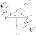
- FIG. 1 is a schematic diagram of a communications system applicable to a data transmission method and apparatus according to an embodiment of the present invention.
- the communications system 100 includes a network device 102, and the network device 102 may include a plurality of antennas, for example, antennas 104, 106, 108, 110, 112, and 114.
- the network device 102 may additionally include a transmitter chain and a receiver chain.
- both the transmitter chain and the receiver chain may include a plurality of components (such as a processor, a modulator, a multiplexer, a demodulator, a demultiplexer, and an antenna) related to signal sending and receiving.
- a processor such as a processor, a modulator, a multiplexer, a demodulator, a demultiplexer, and an antenna
- the network device 102 may be a base transceiver station (Base Transceiver Station, BTS) in global system for mobile communications (global system of mobile communication, GSM) or code division multiple access (Code Division Multiple Access, CDMA); or may be a NodeB (NodeB, NB) in wideband code division multiple access (Wideband Code Division Multiple Access, WCDMA); or may be an evolved NodeB (Evolutional Node B, eNB or eNodeB) in long term evolution (Long Term Evolution, LTE); or a relay station, an access point or a remote radio unit (Remote Radio Unit, RRU); or an in-vehicle device, a wearable device, and a network side device in a future fifth-generation communications (fifth-generation, 5G) network, for example, a Transmission Reception Point (Transmission Reception Point, TRP), a base station, and a base station device.
- BTS Base Transceiver Station
- GSM global system of mobile communication
- the network device 102 may communicate with a plurality of terminal devices (for example, a terminal device 116 and a terminal device 122).
- the network device 102 may communicate with any quantity of terminal devices similar to the terminal device 116 or 122.
- the terminal device 116 or 122 may also be referred to as user equipment (User Equipment, UE), an access terminal, a subscriber unit, a subscriber station, a mobile station, a mobile console, a remote station, a remote terminal, a mobile device, a user terminal, a terminal, a wireless communications device, a user agent, a user apparatus.
- UE user equipment
- UE User Equipment
- the terminal device may be a station (station, ST) in a wireless local area network (Wireless Local Area Networks, WLAN), and may be a cellular phone, a cordless phone, a session initiation protocol (Session Initiation Protocol, SIP) phone, a wireless local loop (Wireless Local Loop, WLL) station, a personal digital assistant (Personal Digital Assistant, PDA) device, a handheld device having a wireless communication function, a computing device, or another processing device connected to a wireless modem, an in-vehicle device, a wearable device, and a next-generation communications system, for example, a terminal device in a fifth-generation (fifth-generation, 5G) network or a terminal device in a future evolved public land mobile network (Public Land Mobile Network, PLMN).
- 5G fifth-generation
- PLMN public Land Mobile Network
- the terminal device 116 communicates with the antennas 112 and 114.
- the antennas 112 and 114 send information to the terminal device 116 by using a forward link 118, and receive information from the terminal device 116 by using a reverse link 120.
- the terminal device 122 communicates with the antennas 104 and 106.
- the antennas 104 and 106 send information to the terminal device 122 by using a forward link 124, and receive information from the terminal device 122 by using a reverse link 126.
- the forward link 118 may use a frequency band different from a frequency band used by the reverse link 120, and the forward link 124 may use a frequency band different from a frequency band used by the reverse link 126.
- FDD Frequency Division Duplex
- the forward link 118 and the reverse link 120 may use a same frequency band, and the forward link 124 and the reverse link 126 may use a same frequency band.
- Each antenna (or an antenna group including a plurality of antennas) and/or an area designed for communication is referred to as a sector of the network device 102.
- an antenna group may be designed to communicate with a terminal device in the sector within coverage of the network device 102.
- a transmit antenna of the network device 102 may improve signal-to-noise ratios of the forward links 118 and 124 through beamforming.
- the network device 102 sends, through beamforming, a signal to the terminal devices 116 and 122 that are randomly distributed within related coverage, less interference is caused to a mobile device in a neighboring cell.
- the network device 102 and the terminal device 116 or the terminal device 122 may be a wireless communications sending apparatus and/or a wireless communications receiving apparatus.
- the wireless communications sending apparatus may encode the data for transmission.
- the wireless communications sending apparatus may obtain (for example, generate, receive from another communications apparatus, or store in a memory) a particular quantity of data bits to be sent, by using a channel, to the wireless communications receiving apparatus.
- the data bits may be included in a transport block (or a plurality of transport blocks) of the data, and the transport block may be segmented to generate a plurality of code blocks.
- the communications system 100 may be a public land mobile network (PLMN) network, a device-to-device (device to device, D2D) network, a machine-to-machine (machine to machine, M2M) network, or another network.
- PLMN public land mobile network
- D2D device to device
- M2M machine-to-machine
- FIG. 1 is only a simplified schematic diagram of an example for ease of understanding, and the network may further include another network device, which is not shown in FIG. 1 .
- FIG. 2 is a schematic diagram of a downlink physical channel processing process used in an existing LTE system.
- a processing target in the downlink physical channel processing process is a code word, and the code word is usually a bitstream on which coding (including at least channel coding) is performed.
- the code word (code word) is scrambled (scrambling), to generate a scrambled bitstream.
- Modulation mapping (modulation mapping) is performed on the scrambled bitstream, to obtain a modulated symbol flow.
- the modulated symbol flow is mapped to a plurality of symbol layers (or referred to as spatial flows, or spatial layers) through layer mapping (layer mapping).
- the symbol layers are precoded (precoding), to obtain a plurality of precoded symbol flows.
- the precoded symbol flows are mapped by a resource unit (resource element, RE) to a plurality of REs. These REs are then modulated through orthogonal frequency division multiplexing (orthogonal frequency division multiplexing, OFDM), to generate an OFDM symbol flow.
- OFDM orthogonal frequency division multiplexing
- the OFDM symbol flow is then transmitted through an antenna port (antenna port).
- Spatial division multiplexing spatial division multiplexing
- transmit diversity transmit diversity
- Spatial multiplexing means that a frequency band is repeatedly used in different space.
- an adaptive array antenna can implement space division, different beams are formed in different user directions, and each beam may provide a unique channel not interfered by another user.
- a plurality of terminals may perform transmission by using a same time frequency resource, so that spectrum utilization and system data throughput can be dramatically improved.
- Precoding is an important technology for implementing spatial multiplexing.
- the precoding technology may be preprocessing a transmit end signal on a transmit end, when a channel status is known, that is, processing a to-be-transmitted signal by using a precoding matrix matching a channel resource, so that the precoded to-be-transmitted signal matches the channel, thereby reducing complexity of eliminating inter-channel impact by a receive end. Therefore, receive signal quality (for example, a signal-to-noise ratio (Signal to Interference plus Noise Ratio, SINR)) is improved since a transmitted signal is precoded. Therefore, with the precoding technology, transmission may be performed on a same time frequency resource by a transmit end device and a plurality of receive end devices, that is, MU-MIMO is implemented.
- SINR Signal-to-noise ratio
- precoding is precoding used for implementing spatial multiplexing.
- precoding mentioned in this specification may be more generally described as spatial multiplexing precoding, unless otherwise particularly stated, or if precoding does not conflict with an actual function or an internal logic in a related description thereof.
- Transmit diversity means that redundancy transmission is performed on an original signal (for example, a symbol) in time, frequency, or space (for example, an antenna), or any combination of the foregoing three dimensions, to improve transmission reliability and obtain a diversity gain.
- transmit diversity includes diversity modes, for example, but not limited to, space time transmit diversity (space-time transmit diversity, STTD), space-frequency transmit diversity (space-frequency transmit diversity, SFTD), time switched transmit diversity (time switched transmit diversity, TSTD), frequency switch transmit diversity (frequency switch transmit diversity, FSTD), orthogonal transmit diversity (orthogonal transmit diversity, OTD), cyclic delay diversity (cyclic delay diversity, CDD), and layer shifting (layer shifting); diversity modes derived from, evolved from, and combined by the foregoing diversity modes; and spatial multiplexing based on the transmit diversity.
- space time transmit diversity space-time transmit diversity
- space-frequency transmit diversity space-frequency transmit diversity
- TSTD time switched transmit diversity
- frequency switch transmit diversity frequency switch transmit diversity
- OFTD orthogonal transmit diversity
- cyclic delay diversity cyclic delay diversity
- CDD cyclic delay diversity
- layer shifting layer shifting
- the MU-MIMO only supports a transmit end device and a plurality of receive end devices in transmitting data by using a same time frequency resource and a same transmission scheme (or referred to as a transmission mode, or transmission scheme).
- the transmission scheme described herein may be a transmission scheme defined in an existing protocol (for example, an LTE protocol), or may be a transmission scheme defined in a future 5G-related protocol. This is not particularly limited in the present invention. It should be understood that, the transmission scheme may be understood as a name of a technical solution used for transmitting data, and should not constitute any limitation on the present invention. The present invention does not exclude a possibility that the transmission scheme is replaced with another name in a future protocol.
- a network device simultaneously transmits data to a plurality of terminal devices through closed loop spatial multiplexing (close loop spatial multiplexing, CLSM).
- CLSM closed loop spatial multiplexing
- channel environments are different.
- quality of a received signal may be better.
- quality of a received signal is relatively poor, and a transmit diversity mode may be used to obtain a diversity gain.
- a transmit end device transmits data to a plurality of receive end devices by using different transmission schemes.
- This application provides a data sending method and a data receiving method, so that the network device can send data to at least two terminal devices on a same time frequency resource, that is, perform downlink transmission; or at least two terminal devices can send data to a same network device on a same time frequency resource, that is, perform uplink transmission.
- the data sending method and the data receiving method in the embodiments of the present invention are described below by using downlink transmission and uplink transmission as examples with reference to the accompanying drawings.
- FIG. 3 is a schematic flowchart of a data sending method 300 according to an embodiment of the present invention. Specifically, FIG. 3 is a schematic flowchart of sending data to at least two terminal devices by a network device.
- the method 300 includes the following steps.
- a network device precodes a plurality of spatial flows to obtain a plurality of precoded data flows, where the plurality of spatial flows are homed to at least two transmission schemes, and the at least two transmission schemes include precoder cycling.
- the network device may send a spatial flow to a plurality of different terminal devices by using a plurality of transmission schemes.
- the network device may send at least one spatial flow (denoted as a first spatial flow for ease of distinguishing and description, and it may be understood that, the first spatial flow may be one or more layers) to a terminal device (denoted as a first terminal device for ease of distinguishing and description), where a transmission scheme of the at least one spatial flow may be precoder cycling;
- the network device may send at least one spatial flow (denoted as a second spatial flow for ease of distinguishing and description, and it may be understood that, the second spatial flow may be one or more layers) to another terminal device (denoted as a second terminal device for ease of distinguishing and description), where a transmission scheme of the at least one spatial flow may be spatial multiplexing;
- the network device may further send at least two spatial flows (denoted as a third spatial flow for ease of distinguishing and description, and it may be understood that, the third spatial flow may be two or more
- a data flow on which layer mapping is performed is referred to as a spatial flow in this specification.
- various spatial flows described in this specification may alternatively be referred to, in a broad sense, as modulated symbol flows obtained through modulation.
- Transmission scheme 1 spatial multiplexing
- the network device may determine that a transmission scheme used for the third spatial flow sent by the third terminal device may be spatial multiplexing. The network device precodes the third spatial flow to obtain a third precoded data flow.
- a precoding vector corresponding to the third spatial flow may be designed to be orthogonal to a channel of another receiving device other than a target receiving device (that is, the third terminal device) of the third spatial flow, to eliminate interference.
- a precoded data flow obtained through precoding is also referred to as a precoded symbol flow.
- the precoding vector may be designed to be orthogonal to a row vector of a channel matrix of the channel of the another receiving device.
- precoding described in this application refer to various precoding schemes in the prior art, for example, a codebook-based precoding scheme and a non-codebook-based precoding scheme.
- the receiver noise n causes impact on signal receiving, but this is not a core of this application.
- the receiver noise is zero, a signal is to be correctly transmitted.
- there are many solutions for eliminating the noise for brevity, description of a same situation or a similar situation is omitted below.
- HW is referred to as an equivalent channel matrix H eff , which corresponds to a precoded channel.
- Demodulation reference signals demodulation reference signal, DMRS
- spatial flows sent by the network device are precoded by using a same precoding matrix W, and therefore, based on the DMRSs, the equivalent channel matrix H eff can be estimated.
- the DMRSs are mapped to the spatial flows one by one, and therefore, a quantity of the DMRSs is usually equal to a quantity of the spatial flows.
- the spatial multiplexing includes: closed loop spatial multiplexing (close loop spatial multiplexing, CLSM).
- Transmission scheme 2 transmit diversity
- the network device needs to obtain a diversity gain through transmit diversity, and then the network device may send data to the second terminal device by using the transmission scheme of diversity transmit.
- the transmit diversity means a transmission scheme in which transmit diversity preprocessing is performed on an original spatial flow to obtain at least two spatial flows, and then the at least two spatial flows are sent after being precoded.
- the network device may add the transmit diversity preprocessing between layer mapping and precoding, to implement transmit diversity of the spatial flows sent to the second terminal device.
- a spatial flow before the transmit diversity processing is referred to as an original spatial flow.
- the transmit diversity processing may include but is not limited to, for example, above-listed diversity modes such as STTD, SFTD, TSTD, and FSTD.
- a data flow on which layer mapping is performed is referred to as a spatial flow in this specification.
- transmit diversity means generating at least two data flows based on one data flow, so that the data flow may be referred to as an original spatial flow, and the generated at least two data flows may be referred to as spatial flows.
- the original spatial flow described herein may be a modulated symbol flow before or after LTE intermediate layer mapping, or may be a modulated symbol flow in any form, for example, a modulated symbol flow obtained after modulation.
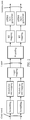
- F2 represents precoding (that is, preprocessing of transmit diversity) corresponding to transmit diversity, and the precoding is used to implement transmit diversity
- F1 represents beamforming (beamforming) precoding (that is, precoding in a conventional sense, which may be referred to precoding defined in the LTE standard), and the beamforming precoding is used to implement spatial multiplexing
- S represents an original spatial flow.
- quantities of ports for sending precoded data flows finally are different. For example, when a transmit diversity processing mode is SFTD, the quantity of ports may be 2; and when a transmit diversity processing mode is FSTD, the quantity of ports may be 4.
- the second spatial flow is precoded to obtain a second precoded data flow.
- the terminal device may obtain a diversity gain through precoder cycling.
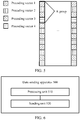
- FIG. 4 is a schematic diagram of precoding different REs on one RB. It can be learned that, in an OFDM symbol, REs corresponding to a plurality of (for example, four) consecutive subcarriers are used as one group, every two of precoding vectors of the REs in each group are different, but precoding vectors of REs corresponding to a group may be the same as another group.
- the plurality of (for example, four, shown in FIG. 4 ) different precoding vectors are cyclically used in a plurality of groups of one RB, and used to precode each RE.
- a precoding granularity is an RE, namely, RE-level (RE-level), which is different from other transmission schemes.
- a precoding granularity of spatial multiplexing and SFBC is an RB, namely, RB-level (RB-level).
- precoder cycling by using four REs as a group.
- more or less REs may be used as a group.
- the plurality of REs in each group may be different in time domain. For example, precoder cycling is performed by using two REs corresponding to an OFDM symbol #0 and an OFDM symbol #1 on a same subcarrier as a group.
- the plurality of REs in each group may be different in frequency domain. For example, precoder cycling is performed by using four REs corresponding to a subcarrier #0 to a subcarrier #4 in a same OFDM symbol as a group.
- the plurality of REs in each group may be different in both time domain and frequency domain.
- precoder cycling is performed by using four REs, namely, an RE corresponding to an OFDM symbol #0 and a subcarrier #0, an RE corresponding to the OFDM symbol #0 and a subcarrier #1, an RE corresponding to an OFDM symbol #1 and the subcarrier #1, and an RE corresponding to the OFDM #1 and the subcarrier #1, as a group.
- examples are not enumerated herein one by one.
- the precoder cycling is a highly reliable transmission scheme.
- the precoder cycling is different from the transmit diversity described in the transmission scheme 2. Specifically, in the precoder cycling, transmit diversity preprocessing does not need to be performed on an original spatial flow, and a diversity gain is obtained during precoding.
- precoder cycling can reduce the process of transmit diversity preprocessing (that is, generating at least two spatial flows by using one spatial flow), so that complexity of processing a spatial flow is reduced, and a diversity gain can be obtained.
- the network device After processing to-be-transmitted spatial flows by using the transmission schemes listed above, the network device obtains the plurality of precoded data flows corresponding to the plurality of spatial flows.
- the network device may process data by using only the transmission schemes of spatial multiplexing and precoder cycling; may process data by using only the transmission schemes of precoder cycling and transmit diversity; or may process data by using the transmission scheme of precoder cycling and another existing transmission scheme, or even a transmission scheme that may be used in future.
- the network device obtains the plurality of precoded data flows after precoding the plurality of spatial flows (for example, including the plurality of spatial flows homed to the transmission scheme 1, the transmission scheme 2, and the transmission scheme 3 in the foregoing description).
- the network device sends the plurality of precoded data flows.
- the terminal devices receive the plurality of precoded data flows.
- a precoding vector corresponding to each spatial flow may be designed to be orthogonal to a channel of another receiving device (for example, the terminal device) other than a target receiving device of the spatial flow. Therefore, when the plurality of precoded data flows reach each receive end device, in addition to a precoded data flow that points to the receive end device and that is in the plurality of precoded data flows, other precoded data flows become zero after being transmitted on a channel from a transmit end device to the receive end device.
- it is difficult to reach the foregoing ideal state so that the other precoded data flows cannot become zero but are greatly reduced when reaching the receive end device, causing small interference to the receive end device.
- the method 300 further includes:
- the network device sends downlink control information (downlink control information, DCI), where the DCI may carry indication information of a transmission scheme.
- DCI downlink control information
- the transmission scheme may be indicated in a DCI format, or may be indicated by using the corresponding indication information carried in the DCI.
- each terminal device determines, based on received DCI, a transmission scheme to which a precoded data flow sent to the terminal device is homed, and demodulates the received precoded data flow based on the transmission scheme and a received precoded demodulation reference signal, to restore a data flow sent to the terminal device.
- a transmission scheme by using which the third terminal device receives the third precoded data flow sent by the network device is spatial multiplexing.
- the third terminal device may demodulate the third precoded data flow based on a received precoded demodulation reference signal corresponding to the third spatial flow.
- W i represents a precoding matrix of a data flow sent to the third terminal device
- W j represents a precoding vector of a data flow sent to other terminal devices (for example, the first terminal device and the second terminal device).
- the receiver noise is zero.
- the third terminal device may process the received signal by using various receiving algorithms, to reduce interference to zero. Specifically, the third terminal device may design each column vector of the precoding matrix W i of the third spatial flow to be orthogonal to each row vector of H j , so that ⁇ j ⁇ i HW j s j is zero, that is, interference is zero. In this way, an equivalent channel matrix may be estimated based on a received DMRS corresponding to a third data flow, and a data flow sent by the network device to the third terminal device may be obtained through demodulation based on the estimated equivalent channel matrix.
- the network device may map the precoded demodulation reference signal and the precoded data flow to a same RB and send the RB to the third terminal device. Therefore, the equivalent channel matrix may be accurately estimated based on the precoded demodulation reference signal, to help the third terminal device demodulate the received precoded data flow.
- the third terminal device can restore the third data flow from the received signal through the precoding processing.
- the network device implements spatial multiplexing through precoding.
- a transmission scheme by using which the second terminal device receives a precoded data flow sent by the network device is transmit diversity.
- the second terminal device may demodulate a second precoded data flow based on a received precoded demodulation reference signal corresponding to the second spatial flow.
- the second spatial flow includes at least two spatial flows obtained by performing transmit diversity on an original spatial flow, and the at least two spatial flows are associated with each other. Therefore, the second precoded data flow cannot be demodulated by separating precoded data flows corresponding to the at least two spatial layers.
- the second terminal device can estimate an equivalent channel matrix of the second precoded data flow based on a received second precoded demodulation reference signal, to obtain a second data flow through demodulation. It should be noted that, the second terminal device obtains at least two spatial flows through demodulating the second precoded data flow. After obtaining the at least two spatial flows through demodulation, the second terminal device may combine the at least two spatial flows into one spatial flow (that is, the original spatial flow), to obtain data bits.
- a transmission scheme by using which the first terminal device receives a first precoded data flow sent by the network device is precoder cycling.
- the first terminal device may demodulate the first precoded data flow based on a received precoded demodulation reference signal corresponding to the first spatial flow.
- demodulation on the third precoded data flow is also based on the RE, and demodulation needs to be performed based on a precoding vector of a demodulation reference signal corresponding to each RE.
- a specific method in which the first terminal device demodulates, based on a precoding vector of a demodulation reference signal corresponding to each RE, data carried on the corresponding RE is similar to the specific method in which the third terminal device demodulates, based on a precoding vector of a demodulation reference signal corresponding to each RB, data carried on the RB. Both the methods can be implemented by using the prior art. For brevity, details are not described herein again.
- the terminal devices can restore the spatial flow from the received precoded data flow.
- the network device may send a precoded data flow to more or less terminal devices.
- Transmission schemes by using which the precoded data flow is sent to the terminal devices may include but are not limited to the schemes listed above, and moreover, different data flows may use a same transmission scheme or different transmission schemes. This is not particularly limited in this application.
- the plurality of spatial flows homed to the at least two transmission schemes are precoded and sent to different terminal devices, so that a spatial degree of freedom is improved, and based on different channel quality, an appropriate transmission scheme can be flexibly used. Moreover, the transmission scheme of precoder cycling is used, and reliability of data transmission can be improved.
- the data sending method 300 in the embodiments of the present invention is described in detail above with reference to FIG. 3 to FIG. 4 .
- the data receiving method 400 in the embodiments of the present invention is described below with reference to FIG. 5 .
- FIG. 5 is a schematic flowchart of the data receiving method 400 according to another embodiment of the present invention. Specifically, FIG. 5 is a schematic flowchart of receiving, by a network device, data sent by at least two terminal devices.
- the method 400 includes the following steps.
- a network device receives a plurality of precoded data flows, where the plurality of precoded data flows are obtained by precoding a plurality of spatial flows by transmit end devices, the plurality of spatial flows are homed to at least two transmission schemes, and the at least two transmission schemes include precoder cycling.
- the plurality of terminal devices may use different transmission schemes, as scheduled by the network device.
- the network device determines a transmission schemes for each terminal device based on current channel quality of the terminal device, and notifies the terminal device based on downlink control information (DCI) on a physical downlink control channel (physical downlink control channel).
- DCI downlink control information
- a first terminal device may send a first precoded data flow to the network device, where the first precoded data flow is obtained by precoding a first spatial flow, and the first spatial flow may be homed to a transmission scheme of spatial multiplexing;
- a second terminal device may send a second precoded data flow to the network device, where the second precoded data flow is obtained by precoding a second spatial flow, and the second spatial flow may be homed to a transmission scheme of transmit diversity;
- a third terminal device sends a third precoded data flow to the network device, where the third precoded data flow is obtained by precoding the third spatial flow, and the third spatial flow may be homed to a transmission scheme of precoder cycling.
- the first spatial flow described herein may correspond to one or more layers
- the third spatial flow may correspond to one or more layers
- the second spatial flow may be obtained by performing transmit diversity preprocessing on an original spatial flow and may correspond to two or more layers.
- a layer may be understood as a spatial flow obtained by performing layer mapping on a modulated symbol flow, or may be understood as a modulated symbol flow in a broad sense.
- the network device restores the plurality of spatial flows from the plurality of precoded data flows.
- the network device may receive signals from the first terminal device, the second terminal device, and the third terminal device, and to restore the first spatial flow, the second spatial flow, and the third spatial flow from the received signals, the network device may eliminate interference by using a receiving algorithm.
- a method for processing the received signals by the network device may be similar to a method for processing the received signals by the various terminal devices in the method 300. For brevity, details are not described herein again.
- the plurality of spatial flows homed to the at least two transmission schemes are precoded by different terminal devices and sent to the network device, so that a spatial degree of freedom is improved, and based on different channel quality, an appropriate transmission scheme can be flexibly used. Moreover, the transmission scheme of precoder cycling is used, and reliability of data transmission can be improved.
- the data sending method and the data receiving method in the embodiments of the present invention are described in detail above with reference to FIG. 3 to FIG. 5 .
- a data sending apparatus and a data receiving apparatus in the embodiments of the present invention are described in detail below with reference to FIG. 6 to FIG. 9 .
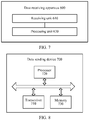
- FIG. 6 is a schematic block diagram of a data sending apparatus 500 according to an embodiment of the present invention. As shown in FIG. 6 , the data sending apparatus 500 includes a processing module 510 and a sending module 520.
- the data sending apparatus 500 may correspond to the network device in the data sending method 300 according to the embodiments of the present invention, and the data sending apparatus 500 may include modules configured to perform the method performed by the network device in the data sending method 300 in FIG. 3 .
- the modules in the data sending apparatus 500 and the foregoing operations and/or functions are for the purpose of implementing the corresponding procedure of the data sending method 300 in FIG. 3 . For brevity, details are not described herein again.
- the processing unit 510 in the data sending apparatus 500 may correspond to (for example, the processing unit 510 is or is configured as) a processor 720 in a data sending device 700 shown in FIG. 8 ; and the sending unit 520 in the data sending apparatus 500 may correspond to (for example, the sending unit 520 is or is configured as) a transceiver 710 in the data sending device 700 shown in FIG. 8 .
- FIG. 7 is a schematic block diagram of a data receiving apparatus 600 according to an embodiment of the present invention. As shown in FIG. 7 , the data receiving apparatus 600 includes a receiving module 610 and a processing module 620.
- the data receiving apparatus 600 may correspond to the network device in the data receiving method 400 in the embodiments of the present invention, and the data receiving apparatus 600 may include modules configured to perform the method performed by the network device in the data receiving method 400 in FIG. 4 .
- the modules in the data receiving apparatus 600 and the foregoing operations and/or functions are for the purpose of implementing the corresponding procedure of the data receiving method 400 in FIG. 4 . For brevity, details are not described herein again.
- the receiving unit 610 in the data receiving apparatus 600 may correspond to (for example, the receiving unit 610 is or is configured as) a transceiver 810 in a data receiving device 800 shown in FIG. 9
- the processing unit 620 in the data receiving apparatus 600 may correspond to (for example, the processing unit 620 is or is configured as) a processor 820 in the data receiving device 800 shown in FIG. 9 .
- FIG. 8 is a schematic block diagram of a data sending device 700 according to an embodiment of the present invention.
- the data sending device 700 includes: a transceiver 710, a processor 720, and a memory 730.
- the transceiver 710, the processor 720, and the memory 730 communicate with each other by using an internally connected channel, to transfer a control and/or data signal.
- the memory 730 is configured to store a computer program
- the processor 720 is configured to invoke the computer program from the memory 730 and run the computer program, to control the transceiver 710 to transmit and receive a signal.
- the memory 730 may be configured in the processor 720, or may be independent of the processor 720.
- the data sending device 700 may correspond to the network device in the data sending method 300 according to the embodiments of the present invention, and the data sending device 700 may include units configured to perform the method performed by the network device in the data sending method 300 in FIG. 3 . Moreover, the units in the data sending device 700 and the foregoing operations and/or functions are for the purpose of implementing the corresponding procedure of the data sending method 300 in FIG. 3 . For brevity, details are not described herein again.
- FIG. 9 is a schematic block diagram of a data receiving device 800 according to an embodiment of the present invention.
- the data receiving device 800 includes: a transceiver 810, a processor 820, and a memory 830.
- the transceiver 810, the processor 820, and the memory 830 communicate with each other by using an internally connected channel, to transfer a control and/or data signal.
- the memory 830 is configured to store a computer program
- the processor 820 is configured to invoke the computer program from the memory 830 and run the computer program, to control the transceiver 810 to transmit and receive a signal.
- the memory 830 may be configured in the processor 820, or may be independent of the processor 820.
- the data receiving device 800 may correspond to the network device in the data receiving method 400 according to the embodiments of the present invention, and the data receiving device 800 may include units configured to perform the method performed by the network device in the data receiving method 400 in FIG. 4 . Moreover, the units in the data receiving device 800 and the foregoing operations and/or functions are for the purpose of implementing the corresponding procedure of the data receiving method 400 in FIG. 4 . For brevity, details are not described herein again.
- the processor in the embodiments of this application may be a central processing unit (central processing unit, CPU), or may further be another general purpose processor, a digital signal processor (digital signal processor, DSP), an application-specific integrated circuit (application specific integrated circuit, ASIC), a field programmable gate array (field programmable gate array, FPGA), or another programmable logical device, discrete gate or transistor logical device, discrete hardware component, or the like.
- CPU central processing unit
- DSP digital signal processor
- ASIC application specific integrated circuit
- FPGA field programmable gate array
- FPGA field programmable gate array
- the memory in the embodiments of the present invention may be a volatile memory or a nonvolatile memory, or may include a volatile memory and a nonvolatile memory.
- the nonvolatile memory may be a read-only memory (read-only memory, ROM), a programmable read-only memory (programmable ROM, PROM), an erasable programmable read-only memory (erasable PROM, EPROM), an electrically erasable programmable read-only memory (electrically EPROM, EEPROM), or a flash memory.
- the volatile memory may be a random access memory (random access memory, RAM), used as an external cache.
- random access memory random access memory
- static random access memory static random access memory
- DRAM dynamic random access memory
- SDRAM synchronous dynamic random access memory
- double data rate SDRAM double data rate SDRAM
- DDR SDRAM double data rate SDRAM
- ESDRAM enhanced synchronous dynamic random access memory
- SCRAM synchronous link dynamic random access memory
- direct rambus RAM direct rambus RAM, DR RAM
- All or some of the foregoing embodiments may be implemented by means of software, hardware, firmware, or any combination thereof.
- the foregoing embodiments may be implemented completely or partially in a form of a computer program product.
- the computer program product includes one or more computer instructions.
- the computer may be a general-purpose computer, a special-purpose computer, a computer network, or other programmable apparatuses.
- the computer instructions may be stored in a computer-readable storage medium or may be transmitted from a computer-readable storage medium to another computer-readable storage medium.
- the computer instructions may be transmitted from a website, computer, server, or data center to another website, computer, server, or data center in a wired (for example, infrared, radio, and microwave, or the like) manner.
- the computer-readable storage medium may be any usable medium accessible by a computer, or a data storage device, such as a server or a data center, integrating one or more usable media.
- the usable medium may be a magnetic medium (for example, a soft disk, a hard disk, or a magnetic tape), an optical medium (for example, a DVD), or a semiconductor medium.
- the semiconductor medium may be a solid-state drive.
- sequence numbers of the foregoing processes do not mean execution sequences in various embodiments of this application.
- the execution sequences of the processes should be determined according to functions and internal logic of the processes, and should not be construed as any limitation on the implementation processes of the embodiments of this application.
- the disclosed system, apparatus, and method may be implemented in other manners.
- the described apparatus embodiment is merely an example.
- the unit division is merely logical function division and may be other division in actual implementation.
- a plurality of units or components may be combined or integrated into another system, or some features may be ignored or not performed.
- the displayed or discussed mutual couplings or direct couplings or communication connections may be implemented by using some interfaces.
- the indirect couplings or communication connections between the apparatuses or units may be implemented in electronic, mechanical, or other forms.
- the units described as separate parts may or may not be physically separate, and parts displayed as units may or may not be physical units, may be located in one position, or may be distributed on a plurality of network units. Some or all of the units may be selected based on actual requirements to achieve the objectives of the solutions of the embodiments.
- the functions When the functions are implemented in the form of a software functional unit and sold or used as an independent product, the functions may be stored in a computer-readable storage medium. Based on such an understanding, the technical solutions of this application essentially, or the part contributing to the prior art, or some of the technical solutions may be implemented in a form of a software product.
- the software product is stored in a storage medium, and includes several instructions for instructing a computer device (which may be a personal computer, a server, or a network device) to perform all or some of the steps of the methods described in the embodiments of this application.
- the foregoing storage medium includes: any medium that can store program code, such as a USB flash drive, a removable hard disk, a read-only memory (Read-Only Memory, ROM), a random access memory (Random Access Memory, RAM), a magnetic disk, or an optical disc.
- program code such as a USB flash drive, a removable hard disk, a read-only memory (Read-Only Memory, ROM), a random access memory (Random Access Memory, RAM), a magnetic disk, or an optical disc.
Landscapes
- Engineering & Computer Science (AREA)
- Computer Networks & Wireless Communication (AREA)
- Signal Processing (AREA)
- Power Engineering (AREA)
- Physics & Mathematics (AREA)
- Mathematical Physics (AREA)
- Radio Transmission System (AREA)
- Mobile Radio Communication Systems (AREA)
Applications Claiming Priority (2)
| Application Number | Priority Date | Filing Date | Title |
|---|---|---|---|
| CN201710184597.3A CN108632181A (zh) | 2017-03-24 | 2017-03-24 | 数据发送方法和装置以及数据接收方法和装置 |
| PCT/CN2018/079798 WO2018171622A1 (zh) | 2017-03-24 | 2018-03-21 | 数据发送方法和装置以及数据接收方法和装置 |
Publications (3)
| Publication Number | Publication Date |
|---|---|
| EP3576362A1 true EP3576362A1 (de) | 2019-12-04 |
| EP3576362A4 EP3576362A4 (de) | 2020-02-19 |
| EP3576362B1 EP3576362B1 (de) | 2026-01-21 |
Family
ID=63584192
Family Applications (1)
| Application Number | Title | Priority Date | Filing Date |
|---|---|---|---|
| EP18772439.8A Active EP3576362B1 (de) | 2017-03-24 | 2018-03-21 | Datenübertragungsverfahren und -vorrichtung sowie datenempfangsverfahren und -vorrichtung |
Country Status (4)
| Country | Link |
|---|---|
| US (1) | US20200021339A1 (de) |
| EP (1) | EP3576362B1 (de) |
| CN (1) | CN108632181A (de) |
| WO (1) | WO2018171622A1 (de) |
Families Citing this family (2)
| Publication number | Priority date | Publication date | Assignee | Title |
|---|---|---|---|---|
| WO2020000317A1 (en) * | 2018-06-28 | 2020-01-02 | Telefonaktiebolaget Lm Ericsson (Publ) | Methods and devices for channel estimation |
| CN116599556B (zh) * | 2022-02-07 | 2025-11-25 | 中国移动通信有限公司研究院 | 一种无蜂窝无线接入网的实现方法与网络设备 |
Family Cites Families (12)
| Publication number | Priority date | Publication date | Assignee | Title |
|---|---|---|---|---|
| CN101232478A (zh) * | 2007-01-25 | 2008-07-30 | 华为技术有限公司 | 选择配对数据流及对应预编码向量的方法及设备 |
| ES2361200T3 (es) * | 2007-03-21 | 2011-06-14 | Alcatel Lucent | Método para determinar técnicas de transmisión mimo, estación de base y terminal móvil. |
| US8537924B2 (en) * | 2008-01-14 | 2013-09-17 | Telefonaktiebolaget Lm Ericsson (Publ) | Open loop precoder cycling in MIMO communications |
| CN101997649B (zh) * | 2009-08-21 | 2014-12-10 | 中兴通讯股份有限公司 | 一种基于正交分集的mu-mimo处理方法和装置 |
| CN102195697B (zh) * | 2010-03-19 | 2015-01-28 | 中兴通讯股份有限公司 | 多输入多输出波束赋形系统及其数据发送方法 |
| EP3582404B1 (de) * | 2010-11-26 | 2021-06-16 | LG Electronics Inc. | Verfahren zur meldung von kanalinformationen auf basis von verbindungsadaptionen in einem wlan und vorrichtung dafür |
| CN102064870A (zh) * | 2010-12-30 | 2011-05-18 | 中兴通讯股份有限公司 | 数据发送方法及装置 |
| CN102299769B (zh) * | 2011-09-01 | 2014-06-25 | 电信科学技术研究院 | 一种下行控制信息传输方法及装置 |
| WO2013040741A1 (zh) * | 2011-09-19 | 2013-03-28 | 富士通株式会社 | 数据传输方法、系统、发射机和接收机 |
| CN103427885B (zh) * | 2012-05-15 | 2016-09-07 | 中兴通讯股份有限公司 | 传输模式的选择方法及装置 |
| US9882623B2 (en) * | 2014-09-18 | 2018-01-30 | Qualcomm Incorporated | Dual thread feedback design for non-orthogonal channels |
| KR20170102173A (ko) * | 2014-12-31 | 2017-09-07 | 후아웨이 테크놀러지 컴퍼니 리미티드 | 데이터 전송 방법 및 디바이스 |
-
2017
- 2017-03-24 CN CN201710184597.3A patent/CN108632181A/zh active Pending
-
2018
- 2018-03-21 EP EP18772439.8A patent/EP3576362B1/de active Active
- 2018-03-21 WO PCT/CN2018/079798 patent/WO2018171622A1/zh not_active Ceased
-
2019
- 2019-09-23 US US16/578,701 patent/US20200021339A1/en not_active Abandoned
Also Published As
| Publication number | Publication date |
|---|---|
| EP3576362B1 (de) | 2026-01-21 |
| US20200021339A1 (en) | 2020-01-16 |
| EP3576362A4 (de) | 2020-02-19 |
| CN108632181A (zh) | 2018-10-09 |
| WO2018171622A1 (zh) | 2018-09-27 |
Similar Documents
| Publication | Publication Date | Title |
|---|---|---|
| US11683076B2 (en) | Data transmission method and apparatus, and system | |
| US11843557B2 (en) | Electronic device and communication method for inter-cell interference coordination | |
| US11211980B2 (en) | Communication method, network device, terminal device, and system | |
| US11184059B2 (en) | Data transmission method, apparatus, and system | |
| US10785007B2 (en) | Dynamic precoding of shared reference signals | |
| KR102293682B1 (ko) | 첨단 무선 통신 시스템의 csi 보고를 위한 프리코더 코드북 | |
| US10911122B2 (en) | Reference signal sending method, reference signal receiving method, network device, and terminal device | |
| US11750326B2 (en) | Data receiving method, data sending method, and communications apparatus | |
| US11101855B2 (en) | Data sending method, data receiving method, network device, and terminal device | |
| US12185142B2 (en) | Methods and apparatus for configuring W1, W2, and WF for port selection codebook enhancement | |
| CN107302390A (zh) | 用于增强型4tx码本的码本子采样的用户设备和方法 | |
| CN108631988B (zh) | 用于数据传输的方法和装置 | |
| US20200044702A1 (en) | User equipment and base station | |
| US20200021339A1 (en) | Data sending method and apparatus, and data receiving method and apparatus |
Legal Events
| Date | Code | Title | Description |
|---|---|---|---|
| STAA | Information on the status of an ep patent application or granted ep patent |
Free format text: STATUS: THE INTERNATIONAL PUBLICATION HAS BEEN MADE |
|
| PUAI | Public reference made under article 153(3) epc to a published international application that has entered the european phase |
Free format text: ORIGINAL CODE: 0009012 |
|
| STAA | Information on the status of an ep patent application or granted ep patent |
Free format text: STATUS: REQUEST FOR EXAMINATION WAS MADE |
|
| 17P | Request for examination filed |
Effective date: 20190830 |
|
| AK | Designated contracting states |
Kind code of ref document: A1 Designated state(s): AL AT BE BG CH CY CZ DE DK EE ES FI FR GB GR HR HU IE IS IT LI LT LU LV MC MK MT NL NO PL PT RO RS SE SI SK SM TR |
|
| AX | Request for extension of the european patent |
Extension state: BA ME |
|
| A4 | Supplementary search report drawn up and despatched |
Effective date: 20200121 |
|
| RIC1 | Information provided on ipc code assigned before grant |
Ipc: H04B 7/0452 20170101AFI20200115BHEP Ipc: H04B 7/06 20060101ALI20200115BHEP Ipc: H04B 7/0456 20170101ALI20200115BHEP |
|
| DAV | Request for validation of the european patent (deleted) | ||
| DAX | Request for extension of the european patent (deleted) | ||
| STAA | Information on the status of an ep patent application or granted ep patent |
Free format text: STATUS: EXAMINATION IS IN PROGRESS |
|
| 17Q | First examination report despatched |
Effective date: 20210210 |
|
| GRAP | Despatch of communication of intention to grant a patent |
Free format text: ORIGINAL CODE: EPIDOSNIGR1 |
|
| STAA | Information on the status of an ep patent application or granted ep patent |
Free format text: STATUS: GRANT OF PATENT IS INTENDED |
|
| INTG | Intention to grant announced |
Effective date: 20250818 |
|
| GRAS | Grant fee paid |
Free format text: ORIGINAL CODE: EPIDOSNIGR3 |
|
| GRAA | (expected) grant |
Free format text: ORIGINAL CODE: 0009210 |
|
| STAA | Information on the status of an ep patent application or granted ep patent |
Free format text: STATUS: THE PATENT HAS BEEN GRANTED |
|
| AK | Designated contracting states |
Kind code of ref document: B1 Designated state(s): AL AT BE BG CH CY CZ DE DK EE ES FI FR GB GR HR HU IE IS IT LI LT LU LV MC MK MT NL NO PL PT RO RS SE SI SK SM TR |
|
| REG | Reference to a national code |
Ref country code: CH Ref legal event code: F10 Free format text: ST27 STATUS EVENT CODE: U-0-0-F10-F00 (AS PROVIDED BY THE NATIONAL OFFICE) Effective date: 20260121 |
|
| REG | Reference to a national code |
Ref country code: DE Ref legal event code: R096 Ref document number: 602018088709 Country of ref document: DE |
|
| REG | Reference to a national code |
Ref country code: IE Ref legal event code: FG4D |
|
| PGFP | Annual fee paid to national office [announced via postgrant information from national office to epo] |
Ref country code: GB Payment date: 20260209 Year of fee payment: 9 |
|
| PGFP | Annual fee paid to national office [announced via postgrant information from national office to epo] |
Ref country code: DE Payment date: 20260211 Year of fee payment: 9 |