EP3576347B1 - Netzwerkvorrichtungsmomentaufnahmen - Google Patents
Netzwerkvorrichtungsmomentaufnahmen Download PDFInfo
- Publication number
- EP3576347B1 EP3576347B1 EP19176123.8A EP19176123A EP3576347B1 EP 3576347 B1 EP3576347 B1 EP 3576347B1 EP 19176123 A EP19176123 A EP 19176123A EP 3576347 B1 EP3576347 B1 EP 3576347B1
- Authority
- EP
- European Patent Office
- Prior art keywords
- network device
- network
- snapshot copy
- snapshot
- state
- Prior art date
- Legal status (The legal status is an assumption and is not a legal conclusion. Google has not performed a legal analysis and makes no representation as to the accuracy of the status listed.)
- Active
Links
Images


Classifications
-
- G—PHYSICS
- G06—COMPUTING OR CALCULATING; COUNTING
- G06F—ELECTRIC DIGITAL DATA PROCESSING
- G06F11/00—Error detection; Error correction; Monitoring
- G06F11/07—Responding to the occurrence of a fault, e.g. fault tolerance
- G06F11/14—Error detection or correction of the data by redundancy in operations
- G06F11/1446—Point-in-time backing up or restoration of persistent data
-
- H—ELECTRICITY
- H04—ELECTRIC COMMUNICATION TECHNIQUE
- H04L—TRANSMISSION OF DIGITAL INFORMATION, e.g. TELEGRAPHIC COMMUNICATION
- H04L12/00—Data switching networks
- H04L12/28—Data switching networks characterised by path configuration, e.g. LAN [Local Area Networks] or WAN [Wide Area Networks]
- H04L12/46—Interconnection of networks
- H04L12/4641—Virtual LANs, VLANs, e.g. virtual private networks [VPN]
-
- H—ELECTRICITY
- H04—ELECTRIC COMMUNICATION TECHNIQUE
- H04L—TRANSMISSION OF DIGITAL INFORMATION, e.g. TELEGRAPHIC COMMUNICATION
- H04L41/00—Arrangements for maintenance, administration or management of data switching networks, e.g. of packet switching networks
- H04L41/08—Configuration management of networks or network elements
- H04L41/085—Retrieval of network configuration; Tracking network configuration history
- H04L41/0853—Retrieval of network configuration; Tracking network configuration history by actively collecting configuration information or by backing up configuration information
-
- H—ELECTRICITY
- H04—ELECTRIC COMMUNICATION TECHNIQUE
- H04L—TRANSMISSION OF DIGITAL INFORMATION, e.g. TELEGRAPHIC COMMUNICATION
- H04L67/00—Network arrangements or protocols for supporting network services or applications
- H04L67/01—Protocols
- H04L67/10—Protocols in which an application is distributed across nodes in the network
- H04L67/1095—Replication or mirroring of data, e.g. scheduling or transport for data synchronisation between network nodes
Definitions
- network connectivity between devices, compute nodes, blades, or frames of a scaleable compute resource may be implemented using a network communication device.
- Network communication devices such as switches, routers, hubs, bridges, etc. represent a primary communication path for sharing data between different types of compute resources generically referred to as "nodes" of a network.
- the shared data may represent inputs to compute processes (e.g., data or applications), outputs of compute resources (e.g., compute results), communications to coordinate distributed processes, communications between users, and other types of data.
- compute processes e.g., data or applications
- outputs of compute resources e.g., compute results
- communications to coordinate distributed processes, communications between users, and other types of data.
- any “intelligent” network communication device there may be a processor, local memory, configuration information, and "current state” information, among other types of information.
- the different types of information on a network device may be considered to represent the overall "device state" at a given point in time.
- information on a network communication device (including its “device state) is expected to change over time, in part, because while in-service and providing active communication paths for a network, the overall configuration and available devices on that network may change.
- a switch may be thought of as a device in a computer network that connects together other devices (generically referred to as "nodes" of the network). Multiple data cables may be plugged into a switch to enable communication between different networked devices. Switches manage the flow of data across a network by transmitting a received network packet only to the one or more devices for which the packet is intended. Each networked device connected to a switch can be identified by its network address, allowing the switch to direct the flow of traffic, possibly in an effort to maximize the security and efficiency of the network.
- a switch is more intelligent than a hub (e.g., Ethernet hub), which simply retransmits packets out of every port of the hub except the port on which the packet was received.
- a hub In most cases, a hub is unable to distinguish different recipients, and therefore may have an overall lower network efficiency, but simpler configuration information, than a switch/router.
- a router is a networking device that forwards data packets between computer networks. Routers perform the traffic directing functions on the Internet. A data packet is typically forwarded from one router to another router through the networks that constitute an internetwork until it reaches its destination node.
- Switches, hubs, Routers, etc. are examples of network communication devices that may benefit from the concepts of this disclosure.
- Other examples of network communication devices that may also benefit include, but are not limited to: wireless access points, remote access servers, bridges, brouters, etc.
- some network communication devices do not fit into a single classification and may be hybrids of two classes of devices (e.g., a brouter is a bridge-router hybrid).
- this disclosure represents an improvement to the art of network computing by providing enhanced diagnostic information that may be used to improve performance, security, and reliability of a network (e.g., a corporate infrastructure network).
- US 7,774,391 discloses a method of universal file access for a heterogeneous computing environment.
- Network device snapshots may be used to capture the overall device state of a network device. Individual snapshots or groups of related snapshots (e.g., from different network devices obtained at a common time period) may be used to diagnose, troubleshoot, or correct anomalies or errors within a computer network.
- the "device state" of a network device may change over time and therefore obfuscate information desired for trouble shooting (e.g., diagnoses) of network errors (or degraded performance periods).
- a "device state” may be thought of to include comprehensive logical and physical device characteristics at a given instant in time.
- Network device snapshots providing the device state may be stored locally on a network device or may be transmitted to external storage on-demand or periodically to accommodate possible limitations of resources on the network device.
- Network device snapshots may be "reloaded” onto devices, for example in a lab or clean-room type environment, for comprehensive analysis. Different types of interfaces into network device snapshots are disclosed.
- An Ethernet switch generally operates at the data link layer (layer 2) of the Open Systems Interconnection (OSI) model to create a separate collision domain for each switch port.
- layer 2 of the Open Systems Interconnection (OSI) model to create a separate collision domain for each switch port.
- Each device connected to a switch port can transfer data to any of the other ports at any time and the transmissions will not interfere with each other. Also, because broadcasts are still being forwarded to all connected devices by the switch, the newly formed network segment (e.g., between the switch port and the attached device) continues to be a broadcast domain.
- Switches may also operate at higher layers of the OSI model, including the network layer and above. A device that also operates at these higher layers may be referred to as a multilayer switch.
- built-in or modular interfaces may make it possible to connect different types of networks, including Ethernet, Fibre Channel, RapidIO, ATM, ITU-T G.hn and 802.11.
- This connectivity can be at different layers of the OSI model. While the layer-2 functionality may be adequate for bandwidth-shifting within one technology, interconnecting technologies such as Ethernet and token ring may be performed more easily at layer 3 or via routing.
- Devices that interconnect at the layer 3 are traditionally called routers, so layer 3 switches can also be regarded as relatively primitive and specialized routers.
- switches may be connected between WAN routers as places for analytic modules.
- Some vendors provide firewall, network intrusion detection, and performance analysis modules that can plug into switch ports. Some of these functions may be on combined modules or integrated into a network device itself.
- a router is another type of network computing device that may benefit from the concepts of this disclosure.
- a router is a networking device that forwards data packets between computer networks. Routers perform the traffic directing functions on the Internet. A data packet is typically forwarded from one router to another router through the networks that constitute an internetwork until it reaches its destination node.
- a router In a typical configuration, a router is connected to two or more data lines from different networks. In this configuration, when a data packet comes in on one of the lines, the router reads the network address information in the packet to determine the ultimate destination. Then, using information in its routing table or routing policy, it directs the packet to the next network on its journey.
- the routers can exchange information about destination addresses using a routing protocol.
- Each router may build up a routing table listing the preferred routes between any two systems on the interconnected networks.
- network communication devices range from simple forwarding type devices (e.g., hub) to more "intelligent” devices that "learn” about a network topology and attempt to make communications more efficient (e.g., switch/router).
- Devices that have intelligence likely contain configuration information and run-time control information (e.g., routing tables) that may change dynamically as packets are exchanged through that device.
- Other types of network devices may also be classified as "intelligent" devices that perform communication connectivity and may benefit from the concepts of this disclosure (e.g., wireless access point, hot-spots, etc.).
- Each of these intelligent network communication devices may be considered to have a "state" that represents an instantaneous view into the operational capabilities, current configuration, and current processor attributes (e.g., code execution information, memory usage, and register settings) of that device.
- This overall device state may be captured in a manner (i.e., the disclosed device snapshot) that it may be later recreated to a substantially identical instance of that device.
- the substantially identical instance (including all available instantaneous settings) may be loaded, for example, in a lab replica device or that same device at a later time.
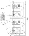
- FIG. 1 an example computer infrastructure 100 is illustrated.
- customer network 105 is connected to a set of frames (represented by frame 1 110, and frame 2 115).
- frame 1 may be configured with a set of blades (B1, B2, ... BN) and a Composable Infrastructure (CI) module.
- CI Composable Infrastructure
- arrow 120-2 indicates that frame 2 may be configured in a like manner.
- Frame 1 further includes two network modules 140 and 145 (sometimes referred to as a Frame Link Module (FLM)).
- Frame 2 also include two network modules 150 and 155. These network modules provide connectivity for the compute resources represented by the blades.
- FLM Frame Link Module
- Each of the blades is shown with a network connection to a network switch 160 disposed within each individual network module (e.g., network module 1, 140).
- Each network module further includes a CPU 165 to facilitate configuration, monitoring, and maintenance of a corresponding network switch 160.
- Network switch 160 is an example of an "embedded" switch that is part of a larger device, in this case a network module and then in turn a Frame. Other network switches may be stand-alone device. In either case, a network switch may be considered a network device in accordance with concepts of this disclosure.
- Connectivity (at a given time) from a set of frames to a customer network is typically provided by a single uplink (e.g., uplink 125) from exactly one of the plurality of network switches that exist across the multiple FLMs of a group of connected frames. That is, all communications external to the group of connected frames passes through uplink 125.
- customer VLAN 130 connects each of the network switches 160 in an ethernet ring network and extends to the customer network 105 (e.g., includes VLANS 1-4094).
- a second ring network, 4095 management VLAN 135, is also shown in FIG. 1 .
- 4095 management VLAN is shown in a bolder line than customer VLAN 130 and also connects each of the network switches 160. Note, in a proper configuration of a group of frames according to one example high-availability implementation, each network switch will be directly connected to each neighboring switch (either in the same frame or an adjacent frame) and no intervening network devices are present.
- a virtual LAN refers to a broadcast domain that is partitioned and isolated in a computer network at the data link layer (OSI layer 2).
- OSI layer 2 data link layer 2
- LAN is the abbreviation for local area network and, in this context, virtual refers to a physical object recreated and altered by additional logic.
- a VLAN is a custom network created from one or more existing LANs. It enables groups of devices from multiple networks (both wired and wireless) to be combined into a single logical network. The result is a virtual LAN that can be administered like a physical local area network, for example 4095 management VLAN 135 in FIG. 1 .
- Each network switch 160 may have a different device state with respect to other network switches and that device state may change over time. Accordingly, capture of a network device snapshot across all network modules of a set of frames may be helpful to diagnose any communication issues experienced by the comprehensive set of related compute devices.
- computer infrastructure 200 illustrates another connectivity possibility between independent network frames or possibly independent clusters of compute resources.
- the links between cluster compute resources Cluster 1 (210) and Cluster 2 (215) do not represent a direct connection.
- Cluster 1 (210) and Cluster 2 (215) may be thought of as independent but related cluster resources.
- Cluster 2 (215) may be configured as a "hot backup" to Cluster 1 (210).
- Communication path 235 may provide communication directly between Cluster 1 (210) and Cluster 2 (215) to support exchange of role information and heartbeat information as appropriate.
- an external network device such as bridge/router 270 has been inserted to form a communication path between distinct compute resources and possibly provide additional communication to other devices (not shown) and networks (not shown). Accordingly, the state of external network device 270 may, at some point, require trouble shooting (or monitoring) and the device snapshots of this disclosure may assist in that effort.
- a computer infrastructure 200 may include a plurality of different types of network devices (e.g., switch, router, bridge, etc.) that may all benefit from the disclosed embodiments of snapshot capture. Accordingly, examples of this disclosure are not limited to any particular type of network connectivity device and may be applicable to any network device that maintains an internal "state" of processing or connectivity when performing its function.
- network devices with state include each instance of network switch 260 and external network device 270.
- a device with a strict hardware only coupling, where no processing takes place, may not be a candidate for snapshot, because there may be no "state” capture possible.
- any device that maintains internal adjustable configuration information may be considered to have a "state" for which a snapshot may be made in accordance with this disclosure. In cases where a device does not include internal memory, the state may be captured directly to external storage.
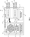
- a network device such as a switch/router 305 is illustrated as in block diagram 300.
- a router has two types of network element components organized onto separate planes illustrated as control plane 310 and data plane 315.
- a typical switch/router 305 may include processing resources and local data storage 320. Depending on the capabilities of a particular switch/router 305 different types of processing resources and local storage may be present. In general, higher capacity router/switch 305 implementations will include substantial processing resources and memory while simpler (e.g., low capacity) devices will contain less internal resources.
- Control plane 310 for example in a router may be used to maintains routing tables (or a single comprehensive routing table) that list which route should be used to forward a data packet, and through which physical interface connection (e.g., output ports 360 through 369). Control plane 310 may perform this function by using internal preconfigured directives, called static routes, or by learning routes dynamically using a routing protocol. Static and dynamic routes may be stored in one or more of the routing tables. The control-plane logic may then strip non-essential directives from the table and build a forwarding information base (FIB) to be used by data plane 315.
- FIB forwarding information base
- a router may also use a forwarding plane (e.g., part of the data plane 315) that contains different forwarding paths for information from different ports or different destination addresses (e.g., forwarding path A 316 or forwarding path Z 317).
- the router forwards data packets between incoming (e.g., ports 350 - 359) and outgoing interface connections (e.g., ports 360 - 359).
- the router forwards data packets to the correct network type using information that the packet header contains matched to entries in the FIB supplied by control plane 310.
- a router e.g., network device 305) may have interfaces for different types of physical layer connections, such as copper cables, fiber optic, or wireless transmission.
- a single router may also support different network layer transmission standards. Each network interface may be used to enable data packets to be forwarded from one transmission system to another. Routers may also be used to connect two or more logical groups of computer devices known as subnets, each with a different network prefix.
- bidirectional arrow 307 indicates that control plane 310 and data plane 315 may work in a coordinated fashion to achieve the overall capabilities of network device 305.
- bidirectional arrow 325 indicates that processing and local data storage resources 320 may interface with control plane 310 to provide processing and storage support for capabilities assigned to control plane 310.
- Bidirectional arrow 330 indicates that processing and local data storage resources 320 may also interface with data plane 315 as necessary.
- Control plane 310 as illustrated in FIG. 3 includes several example functional control blocks. Additional control blocks are possible depending on the capabilities of a particular implementation of a network device 305.
- Block 311 indicates that control plane 310 may have associated build information regarding a software version of control code that is currently executing on network device 305.
- that software version may include configuration settings to determine how network device 305 and its associated control code perform different functions.
- Many different configuration settings for both the software and the device itself are possible and describing each is beyond the scope of this disclosure.
- the disclosed device snapshot may be designed to capture as many of these configuration settings as possible (hopefully all) to accurately capture a network device state.
- Block 311 further indicates that different types of routing information and connectivity information may be known to network device 305 and control plane 310.
- Block 312 indicates that an information store may be accessible from control plane 310 and include forwarding tables or NAT information as appropriate.
- Block 313 indicates that control plan 310 may also be aware of forwarding decisions and other processing information. Although FIG. 3 illustrates these logical capabilities within control plan 310 they may actually be implemented outside of, but accessible to, control plane 310.
- Capabilities of a network device 305 that may benefit from the disclosed snapshot capabilities may vary greatly. Capabilities of different network devices are generally described with respect to how those capabilities map to the OSI model. A brief overview of the different layers and their typical capability mapping is provided in the next few paragraphs to provide context for this disclosure. However, no particular OSI mapping capability is required to practice the concepts of this disclosure and this information should not be considered limiting in any way.
- An Ethernet hub is an example of a simple layer 1 network device (in contrast to a switch that operates at layer 2 and router that operates at layer 3). An Ethernet hub does not manage any of the traffic coming through it. Any packet entering a port may be repeated to the output of every other port except for the port of entry. Specifically, each bit or symbol may be repeated as it flows in.
- a layer 2 switch operating as a network bridge may interconnect devices in a home or office for example.
- the bridge may learn the MAC address of each connected device. Bridges may also buffer an incoming packet and adapt the transmission speed to that of the outgoing port. While there are specialized applications, such as storage area networks, where the input and output interfaces are the same bandwidth, this is not always the case in general LAN applications.
- a switch may be used for end user access and typically concentrates lower bandwidth and uplinks into a higher bandwidth.
- Interconnect between switches may be regulated using spanning tree protocol (STP) that disables links so that the resulting local area network is a tree without loops.
- STP spanning tree protocol
- spanning tree bridges have topologies with only one active path between two points. Shortest path bridging is a layer 2 alternative to STP that allows all paths to be active with multiple equal cost paths.
- Information about the topologies and other information learned by a given network device represent examples of data that may be included in a device snapshot.
- a layer-3 switch can perform some or all of the functions normally performed by a router.
- network switches are limited to supporting a single type of physical network, typically Ethernet, whereas a router may support different kinds of physical networks on different ports.
- a router may support different kinds of physical networks on different ports.
- may combination (e.g., hybrid) devices are possible and can perform a variety of functions such that they do not fit neatly into a single category of device. Regardless, of the overall capabilities of the device, the disclosed device snapshot capability may assist in troubleshooting network anomalies.
- a common layer-3 capability is awareness of IP multicast through IGMP snooping. With this awareness, a layer-3 switch may increase efficiency by delivering the traffic of a multicast group only to ports where the attached device has signaled that it wants to listen to that group.
- Layer-3 switches typically support IP routing between VLANs configured on the switch. Some layer-3 switches support the routing protocols that routers use to exchange information about routes between networks.
- a layer-4 switch almost always includes a capability for network address translation (NAT) and may add some type of load distribution based on Transmission Control Protocol (TCP) sessions or advanced Quality of Service (QoS) capabilities.
- network devices may include a stateful firewall, a VPN concentrator, or be an IPSec security gateway.
- Layer-7 switches may distribute the load based on uniform resource locators (URLs), or by using some installation-specific technique to recognize application-level transactions.
- a layer-7 switch may include a web cache and participate in a content delivery network (CDN).
- CDN content delivery network
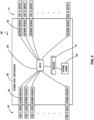
- a simplified network device 405 such as a switch/router is illustrated in block diagram 400.
- a network device 405 may include an internal switch 430 that communicatively connects a set of input ports 410 via a logical or physical network interface 420 to a set of output ports 415 that also have an associated logical or physical network interface 420.
- the communication paths established by switch 430 may be controlled by one or more processors 435 (and possibly corresponding hardware logic) and the processors may obtain and store information in internal memory 440.
- network device 405 represents a relatively basic switch or router architecture that may benefit from the disclosed network device snapshot techniques.
- one example method to capture device snapshots includes a technique to "pause" execution of a network device for a short period of time and capture the operational state of that network device (e.g., network device 405).
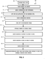
- FIG. 5 illustrates an example method 500, starting at start block 505, that may be performed for each network device in the snapshot process.
- a network device may be active and performing its intended function to support network communications.
- a request for a network device snapshot may be received as indicated at block 510.
- Block 515 indicates that, as a result of that request, communications and functions of the network device may be quiesced (e.g., made quiet or suspended) for a temporary period long enough to obtain a consistent state of the network device.
- Many techniques for quiescing a device are possible, but in general these techniques pause new activities for a short period of time while continuing processing to complete any in-progress activities such that all processing is at a consistent state without transient inconsistent information across processes.
- block 520 indicates that a copy of state data, including application processing and hardware state, may be created to form a snapshot.
- state data including application processing and hardware state
- One example of capturing application state includes an operating system function to "fork" a process such that two identical processes are created, and changes are only applied to one of the forks when processing is continued. Other techniques are also possible.
- Block 535 indicates that processing may be resumed, and communication sessions of the network device may continue (possibly overlapping a time period where the snapshot is still being saved).
- Block 530 indicates that a copy of the snapshot may be made to non-transitory storage (e.g., in local memory storage of the device).
- Block 535 indicates that one or more snapshots may be optionally transmitted to external storage. For example, to conserve resources of the network device or to begin further analysis of the snapshot on non-production devices.
- Block 540 illustrates that an indication of a snapshot to restore may be received. For example, from a user wanting to interrogate a particular device snapshot.
- Block 545 illustrates that a second indication of a device on which to restore the snapshot may be received.
- Block 550 indicates that the snapshot may be restored to the identified device. For example, for troubleshooting of a network anomaly that occurred at or around the time period when the snapshot was saved.
- Method 500 completes with block 555 where either an internal interface of the device that was restored may be used, or an external device connected to the "restored device" may be used to interrogate or troubleshoot the above-mentioned network anomaly.
- method 600 represents portions of a technique to capture and use network device snapshots from the perspective of a network device (e.g., 305 or 405).
- Method 600 begins at block 605 with an active network device.
- Block 610 indicates that the activities of the network device may be quiesced as described above for method 500.
- Block 615 indicates that a copy of state data for both hardware and software may be created.
- Block 620 indicates that communications of the network device may be resumed.
- Block 625 indicates that a copy of the snapshot may be stored to non-transitory storage (or possibly volatile storage for a period of time).
- Block 630 indicates that the snapshot may be optionally transmitted to external storage as explained above for method 500.
- method 650 represents portions of a technique to capture and use network device snapshots from the perspective of an interrogating device or copy of a network device in a non-production (e.g., clean-room) environment.
- the snapshot may optionally be restored to the same device on which it was captured but that is not the point of this particular example.
- Block 655 illustrates that an indication to restore a captured snapshot to a test device, for example, may be received.
- Block 660 illustrates that a user, for example, may provide an indication of which test device to configure based on the identified snapshot.
- Block 665 indicates that the snapshot may be restored (e.g., loaded) as requested.
- Block 670 indicates that troubleshooting or other diagnostic functions, including interrogation of application values, stored data, or configuration information, may be performed on the test device using an internal interface of the test device or another device communicatively coupled to the test device.
- a test device is utilized to explain methods 600 and 650 a related set of devices may also be restored to a time period of a network anomaly because it is common that interaction between different devices may be the cause of the network anomaly.
- a test environment may include portions of the network infrastructure being diagnosed and may include a number of machines in addition to the network devices. For example, enough resources to recreate and troubleshoot a potentially complex network condition.
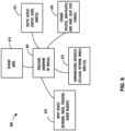
- FIG. 7 represents a computer network infrastructure 700 that may be used to implement all or part of the disclosed network device snapshot technique or provide information flow between a system performing the technique and other computer networks, according to one or more disclosed embodiment.
- Network infrastructure 700 includes a set of networks where embodiments of the present disclosure may operate.
- Network infrastructure 700 comprises a customer network 702, network 708, cellular network 703, and a cloud service provider network 710.
- the customer network 702 may be a local private network, such as local area network (LAN) that includes a variety of network devices that include, but are not limited to switches, servers, and routers.
- LAN local area network
- customer network 702 represents an enterprise network that could include or be communicatively coupled to one or more local area networks (LANs), virtual networks, data centers and/or other remote networks (e.g., 708, 710).
- LANs local area networks
- customer network 702 may include a network device snapshot method such as that described above.
- customer network 702 may be connected to one or more client devices 704A-E and allow the client devices 704A-E to communicate with each other and/or with cloud service provider network 710, via network 708 (e.g., Internet).
- Client devices 704A-E may be computing systems such as desktop computer 704B, tablet computer 704C, mobile phone 704D, laptop computer (shown as wireless) 704E, and/or other types of computing systems generically shown as client device 704A.
- Network infrastructure 700 may also include other types of devices generally referred to as Internet of Things (IoT) (e.g., edge IOT device 705) that may be configured to send and receive information via a network to access cloud computing services or interact with a remote web browser application (e.g., to receive configuration information).
- IoT Internet of Things
- edge IOT device 705 may be configured to send and receive information via a network to access cloud computing services or interact with a remote web browser application (e.g., to receive configuration information).
- FIG. 7 also illustrates that customer network 702 includes local compute resources 706A-C that may include a server, access point, router, or other device configured to provide for local computational resources and/or facilitate communication amongst networks and devices.
- local compute resources 706A-C may be one or more physical local hardware devices, such as the frames outlined above.
- Local compute resources 706A-C may also facilitate communication between other external applications, data sources ( e . g ., 707A and 707B), and services, and customer network 702.
- Network infrastructure 700 also includes cellular network 703 for use with mobile communication devices.
- Mobile cellular networks support mobile phones and many other types of mobile devices such as laptops etc.
- Mobile devices in network infrastructure 700 are illustrated as mobile phone 704D, laptop computer 704E, and tablet computer 704C.
- a mobile device such as mobile phone 704D may interact with one or more mobile provider networks as the mobile device moves, typically interacting with a plurality of mobile network towers 720, 730, and 740 for connecting to the cellular network 703.
- FIG. 7 illustrates that customer network 702 is coupled to a network 708.
- Network 708 may include one or more computing networks available today, such as other LANs, wide area networks (WAN), the Internet, and/or other remote networks, in order to transfer data between client devices 704A-D and cloud service provider network 710.
- Each of the computing networks within network 708 may contain wired and/or wireless programmable devices that operate in the electrical and/or optical domain.
- cloud service provider network 710 is illustrated as a remote network (e.g., a cloud network) that is able to communicate with client devices 704A-E via customer network 702 and network 708.
- the cloud service provider network 710 acts as a platform that provides additional computing resources to the client devices 704A-E and/or customer network 702.
- cloud service provider network 710 includes one or more data centers 712 with one or more server instances 714.
- Cloud service provider network 710 may also include one or more frames representing a scalable compute resource that may benefit from the techniques of this disclosure.
- FIG. 8 illustrates a computing device 800 that may be used to implement the functions, modules, processing platforms, execution platforms, communication devices, and other methods and processes of this disclosure.
- computing device 800 illustrated in FIG. 8 could represent a client device or a physical server device and include either hardware or virtual processor(s) depending on the level of abstraction of the computing device.
- computing device 800 and its elements, as shown in FIG. 8 each relate to physical hardware.
- one, more, or all of the elements could be implemented using emulators or virtual machines as levels of abstraction.
- computing device 800 at its lowest level may be implemented on physical hardware.
- computing device 800 may include one or more input devices 830, such as a keyboard, mouse, touchpad, or sensor readout (e . g ., biometric scanner) and one or more output devices 815, such as displays, speakers for audio, or printers. Some devices may be configured as input/output devices also (e . g ., a network interface or touchscreen display).
- input devices 830 such as a keyboard, mouse, touchpad, or sensor readout (e . g ., biometric scanner)
- output devices 815 such as displays, speakers for audio, or printers.
- Some devices may be configured as input/output devices also (e . g ., a network interface or touchscreen display).
- Computing device 800 may also include communications interfaces 825, such as a network communication unit that could include a wired communication component and/or a wireless communications component, which may be communicatively coupled to processor 805.
- the network communication unit may utilize any of a variety of proprietary or standardized network protocols, such as Ethernet, TCP/IP, to name a few of many protocols, to effect communications between devices.
- Network communication units may also comprise one or more transceiver(s) that utilize the Ethernet, power line communication (PLC), WiFi, cellular, and/or other communication methods.
- computing device 800 includes a processing element such as processor 805 that contains one or more hardware processors, where each hardware processor may have a single or multiple processor cores.
- the processor 805 may include at least one shared cache that stores data (e . g ., computing instructions) that are utilized by one or more other components of processor 805.
- the shared cache may be a locally cached data stored in a memory for faster access by components of the processing elements that make up processor 805.
- the shared cache may include one or more mid-level caches, such as level 2 (L2), level 3 (L3), level 4 (L4), or other levels of cache, a last level cache (LLC), or combinations thereof.
- LLC last level cache
- processors include but are not limited to a central processing unit (CPU) a microprocessor. Although not illustrated in FIG. 8 , the processing elements that make up processor 805 may also include one or more of other types of hardware processing components, such as graphics processing units (GPU), application specific integrated circuits (ASICs), field-programmable gate arrays (FPGAs), and/or digital signal processors (DSPs).
- GPU graphics processing units
- ASICs application specific integrated circuits
- FPGAs field-programmable gate arrays
- DSPs digital signal processors
- FIG. 8 illustrates that memory 810 may be operatively and communicatively coupled to processor 805.
- Memory 810 may be a non-transitory medium configured to store various types of data.
- memory 810 may include one or more storage devices 820 that comprise a non-volatile storage device and/or volatile memory.
- Volatile memory such as random-access memory (RAM)
- RAM random-access memory
- the non-volatile storage devices 820 can include one or more disk drives, optical drives, solid-state drives (SSDs), tap drives, flash memory, read only memory (ROM), and/or any other type of memory designed to maintain data for a duration of time after a power loss or shut down operation.
- the non-volatile storage devices 820 may be used to store overflow data if allocated RAM is not large enough to hold all working data.
- the non-volatile storage devices 820 may also be used to store programs that are loaded into the RAM when such programs are selected for execution.
- the compiling process of the software program may transform program code written in a programming language to another computer language such that the processor 805 is able to execute the programming code.
- the compiling process of the software program may generate an executable program that provides encoded instructions (e . g ., machine code instructions) for processor 805 to accomplish specific, non-generic, particular computing functions.
- the encoded instructions may then be loaded as computer executable instructions or process steps to processor 805 from storage device 820, from memory 810, and/or embedded within processor 805 ( e . g ., via a cache or on-board ROM).
- Processor 805 may be configured to execute the stored instructions or process steps in order to perform instructions or process steps to transform the computing device into a non-generic, particular, specially programmed machine or apparatus.
- Stored data, e . g ., data stored by a storage device 820 may be accessed by processor 805 during the execution of computer executable instructions or process steps to instruct one or more components within the computing device 800.
- a user interface can include a display, positional input device (such as a mouse, touchpad, touchscreen, or the like), keyboard, or other forms of user input and output devices.
- the user interface components may be communicatively coupled to processor 805.
- the output device is or includes a display
- the display can be implemented in various ways, including by a liquid crystal display (LCD) or a cathode-ray tube (CRT) or light emitting diode (LED) display, such as an organic light emitting diode (OLED) display.
- LCD liquid crystal display
- CRT cathode-ray tube
- LED light emitting diode
- OLED organic light emitting diode
Landscapes
- Engineering & Computer Science (AREA)
- Computer Networks & Wireless Communication (AREA)
- Signal Processing (AREA)
- Theoretical Computer Science (AREA)
- Quality & Reliability (AREA)
- Physics & Mathematics (AREA)
- General Engineering & Computer Science (AREA)
- General Physics & Mathematics (AREA)
- Computer Security & Cryptography (AREA)
- Data Exchanges In Wide-Area Networks (AREA)
- Environmental & Geological Engineering (AREA)
Claims (12)
- Computerimplementiertes Verfahren (500), umfassend:Empfangen (510) eines Hinweises, eine erste Netzwerkvorrichtung stillzulegen;Pausieren (515) der Verarbeitung neuer Kommunikation in der ersten Netzwerkvorrichtung für einen ersten Zeitraum, der ausreicht, um die Verarbeitung mindestens eines Teils von jeglicher laufender Kommunikation in der ersten Netzwerkvorrichtung abzuschließen;Erzeugen (520) einer ersten Momentaufnahmenkopie eines ersten Zustands der ersten Netzwerkvorrichtung, wobei der erste Zustand Informationen von der ersten Netzwerkvorrichtung enthält, die Laufzeitausführungsparameter einer Softwareanwendung, Konfigurationsparameter einer Softwareanwendung,Laufzeitausführungsparameter von Hardware und Konfigurationsparameter von Hardware beschreiben;Wiederaufnehmen (525) von Kommunikationsverarbeitung in der ersten Netzwerkvorrichtung;Speichern (530) der ersten Momentaufnahmenkopie des ersten Zustands der ersten Netzwerkvorrichtung in einem ersten Speicher, der kommunikativ mit einem ersten Prozessor der ersten Netzwerkvorrichtung verbunden ist;Empfangen eines Hinweises, eine zweite Netzwerkvorrichtung gleichzeitig mit dem Stilllegen der ersten Netzwerkvorrichtung stillzulegen;Pausieren der Verarbeitung neuer Kommunikation in der zweiten Netzwerkvorrichtung für einen zweiten Zeitraum, der ausreicht, um die Verarbeitung mindestens eines Teils von jeglicher laufender Kommunikation in der zweiten Netzwerkvorrichtung abzuschließen;Erzeugen einer zweiten Momentaufnahmenkopie eines zweiten Zustands der zweiten Netzwerkvorrichtung, wobei der zweite Zustand Informationen von der zweiten Netzwerkvorrichtung enthält, die Laufzeitausführungsparameter einer Softwareanwendung, Konfigurationsparameter einer Softwareanwendung,Laufzeitausführungsparameter von Hardware und Konfigurationsparameter von Hardware beschreiben;Wiederaufnehmen von Kommunikationsverarbeitung in derzweiten Netzwerkvorrichtung;Speichern derzweiten Momentaufnahmenkopie des zweiten Zustands der zweiten Netzwerkvorrichtung in einem zweiten Speicher, der kommunikativ mit einem zweiten Prozessor der zweiten Netzwerkvorrichtung verbunden ist;Wiederherstellen der ersten Momentaufnahmenkopie in einer dritten Netzwerkvorrichtung;Wiederherstellen der zweiten Momentaufnahmenkopie in einer vierten Netzwerkvorrichtung; undDiagnostizieren einer Netzwerkanomalie unter Verwendung von Informationen von der dritten Netzwerkvorrichtung und der vierten Netzwerkvorrichtung.
- Computerimplementiertes Verfahren (500) nach Anspruch 1, wobei der erste Speicher lokalen Speicherplatz der ersten Netzwerkvorrichtung umfasst.
- Computerimplementiertes Verfahren (500) nach Anspruch 1, ferner umfassend das Übertragen (535) einer ersten Kopie der ersten Momentaufnahmenkopie auf einen externen Speicherplatz.
- Computerimplementiertes Verfahren (500) nach Anspruch 1, wobei der zweite Speicher lokalen Speicherplatz der zweiten Netzwerkvorrichtung umfasst.
- Computerimplementiertes Verfahren (500) nach Anspruch 1, ferner umfassend das Übertragen einer zweiten Kopie der zweiten Momentaufnahmenkopie auf einen externen Speicherplatz.
- Computerimplementiertes Verfahren (500) nach Anspruch 1, ferner umfassend das Wiederherstellen der ersten Momentaufnahmenkopie in der ersten Netzwerkvorrichtung.
- Computerimplementiertes Verfahren (500) nach Anspruch 6, ferner umfassend das Diagnostizieren der Netzwerkanomalie unter Verwendung von Informationen von der ersten Netzwerkvorrichtung nach dem Abschließen einer Wiederherstellung der ersten Momentaufnahmenkopie.
- Nicht flüchtiges, computerlesbares Medium (810), umfassend darauf gespeicherte computerausführbare Anweisungen, die, wenn sie durch eine oder mehrere Verarbeitungseinheiten (805) ausgeführt werden, ein Verfahren (500) zum Erzeugen einer Netzwerkvorrichtungsmomentaufnahme ausführen, wobei das Verfahren umfasst:Empfangen (510) eines Hinweises, eine erste Netzwerkvorrichtung stillzulegen;Pausieren (515) der Verarbeitung neuer Kommunikation in der ersten Netzwerkvorrichtung für einen ersten Zeitraum, der ausreicht, um die Verarbeitung mindestens eines Teils von jeglicher laufender Kommunikation in der ersten Netzwerkvorrichtung abzuschließen;Erzeugen (520) einer ersten Momentaufnahmenkopie eines ersten Zustands der ersten Netzwerkvorrichtung, wobei der erste Zustand Informationen von der ersten Netzwerkvorrichtung enthält, die Laufzeitausführungsparameter einer Softwareanwendung, Konfigurationsparameter einer Softwareanwendung,Laufzeitausführungsparameter von Hardware und Konfigurationsparameter von Hardware beschreiben;Wiederaufnehmen (525) von Kommunikationsverarbeitung in der ersten Netzwerkvorrichtung;Speichern (530) der ersten Momentaufnahmenkopie des ersten Zustands der ersten Netzwerkvorrichtung in einem ersten Speicher, der kommunikativ mit einem ersten Prozessor der ersten Netzwerkvorrichtung verbunden ist;Empfangen eines Hinweises, eine zweite Netzwerkvorrichtung gleichzeitig mit dem Stilllegen der ersten Netzwerkvorrichtung stillzulegen;Pausieren der Verarbeitung neuer Kommunikation in der zweiten Netzwerkvorrichtung für einen zweiten Zeitraum, der ausreicht, um die Verarbeitung mindestens eines Teils von jeglicher laufender Kommunikation in der zweiten Netzwerkvorrichtung abzuschließen;Erzeugen einer zweiten Momentaufnahmenkopie eines zweiten Zustands der zweiten Netzwerkvorrichtung, die Laufzeitausführungsparameter einer Softwareanwendung,Konfigurationsparameter einer Softwareanwendung, Laufzeitausführungsparameter von Hardware und Konfigurationsparameter von Hardware beschreibt;Wiederaufnehmen von Kommunikationsverarbeitung in derzweiten Netzwerkvorrichtung;Speichern derzweiten Momentaufnahmenkopie des zweiten Zustands derzweiten Netzwerkvorrichtung in einem zweiten Speicher, der kommunikativ mit einem zweiten Prozessor der zweiten Netzwerkvorrichtung verbunden ist;Initiieren des Wiederherstellens der ersten Momentaufnahmenkopie auf einer dritten Netzwerkvorrichtung;Initiieren des Wiederherstellens der zweiten Momentaufnahmenkopie auf einer vierten Netzwerkvorrichtung; undDiagnostizieren einer Netzwerkanomalie unter Verwendung von Informationen von der dritten Netzwerkvorrichtung und der vierten Netzwerkvorrichtung.
- Nicht flüchtiges, computerlesbares Medium (810) nach Anspruch 8, wobei das Verfahren ferner umfasst:
Übertragen (535) einer ersten Kopie der ersten Momentaufnahmenkopie auf einen externen Speicherplatz. - Nicht flüchtiges, computerlesbares Medium (810) nach Anspruch 8, wobei die erste Momentaufnahmenkopie und die zweite Momentaufnahmenkopie zur Wiederherstellung von einer einzelnen Vorrichtung erhalten werden.
- Computernetzwerkvorrichtung (160, 260, 270, 305, 405), umfassend:eine erste Verarbeitungseinheit (435);eine erste Netzwerkkommunikationsschnittstelle (420), welche die erste Verarbeitungsvorrichtung kommunikativ mit einem Computernetzwerk verbindet; undeinen Speicher (440), kommunikativ verbunden mit der ersten Verarbeitungseinheit,wobei der SpeicherAnweisungen speichert, die, wenn sie durch die erste Verarbeitungseinheit ausgeführt werden, die ersten Verarbeitungseinheiten veranlassen, eine Netzwerkvorrichtungsmomentaufnahmenfunktion auszuführen, wobei die Netzwerkvorrichtungsmomentaufnahmenfunktion dazu konfiguriert ist:einen Hinweis zu empfangen, eine erste Netzwerkvorrichtung stillzulegen;die Verarbeitung neuer Kommunikation in der ersten Netzwerkvorrichtung für einen ersten Zeitraum, der ausreicht, um die Verarbeitung mindestens eines Teils von jeglicher laufender Kommunikation in der ersten Netzwerkvorrichtung abzuschließen, zu pausieren;eine erste Momentaufnahmenkopie eines ersten Zustands der ersten Netzwerkvorrichtung zu erzeugen, wobei der erste Zustand Informationen von der ersten Netzwerkvorrichtung enthält, die Laufzeitausführungsparameter einer Softwareanwendung, Konfigurationsparameter einer Softwareanwendung,Laufzeitausführungsparameter von Hardware und Konfigurationsparameter von Hardware beschreiben;Kommunikationsverarbeitung in der ersten Netzwerkvorrichtung wiederaufzunehmen;die erste Momentaufnahmenkopie des ersten Zustands der ersten Netzwerkvorrichtung in einem ersten Speicher, der kommunikativ mit einem ersten Prozessor der ersten Netzwerkvorrichtung verbunden ist, zu speichern;einen Hinweis, eine zweite Netzwerkvorrichtung gleichzeitig mit dem Stilllegen der ersten Netzwerkvorrichtung stillzulegen, zu empfangen;die Verarbeitung neuer Kommunikation in der zweiten Netzwerkvorrichtung für einen zweiten Zeitraum, der ausreicht, um die Verarbeitung mindestens eines Teils von jeglicher laufender Kommunikation in der zweiten Netzwerkvorrichtung abzuschließen, zu pausieren;eine zweite Momentaufnahmenkopie eines zweiten Zustand der zweiten Netzwerkvorrichtung zu erzeugen, wobei der zweite Zustand Informationen von der zweiten Netzwerkvorrichtung enthält, die Laufzeitausführungsparameter einer Softwareanwendung, Konfigurationsparameter einer Softwareanwendung,Laufzeitausführungsparameter von Hardware und Konfigurationsparameter von Hardware beschreiben;Kommunikationsverarbeitung in derzweiten Netzwerkvorrichtung wiederaufzunehmen;die zweite Momentaufnahmenkopie des zweiten Zustands der zweiten Netzwerkvorrichtung in einem zweiten Speicher, der kommunikativ mit einem zweiten Prozessor der zweiten Netzwerkvorrichtung verbunden ist, zu speichern;die erste Momentaufnahmenkopie auf einer dritten Netzwerkvorrichtung wiederherzustellen;die zweite Momentaufnahmenkopie auf einer vierten Netzwerkvorrichtung wiederherzustellen; undeine Netzwerkanomalie unterVerwendung von Informationen von der dritten Netzwerkvorrichtung und der vierten Netzwerkvorrichtung zu diagnostizieren.
- Computernetzwerkvorrichtung (160, 260, 270, 305, 405) nach Anspruch 11, wobei der Speicher einen lokalen Speicher umfasst, und/oder wobei die Netzwerkvorrichtungsmomentaufnahmenfunktion ferner dazu konfiguriert ist, eine Kopie der ersten Momentaufnahmenkopie auf einen externen Speicherplatz zu übertragen.
Applications Claiming Priority (1)
| Application Number | Priority Date | Filing Date | Title |
|---|---|---|---|
| US15/993,713 US10693753B2 (en) | 2018-05-31 | 2018-05-31 | Network device snapshots |
Publications (2)
| Publication Number | Publication Date |
|---|---|
| EP3576347A1 EP3576347A1 (de) | 2019-12-04 |
| EP3576347B1 true EP3576347B1 (de) | 2024-07-17 |
Family
ID=66647081
Family Applications (1)
| Application Number | Title | Priority Date | Filing Date |
|---|---|---|---|
| EP19176123.8A Active EP3576347B1 (de) | 2018-05-31 | 2019-05-23 | Netzwerkvorrichtungsmomentaufnahmen |
Country Status (2)
| Country | Link |
|---|---|
| US (2) | US10693753B2 (de) |
| EP (1) | EP3576347B1 (de) |
Families Citing this family (7)
| Publication number | Priority date | Publication date | Assignee | Title |
|---|---|---|---|---|
| US10379988B2 (en) * | 2012-12-21 | 2019-08-13 | Commvault Systems, Inc. | Systems and methods for performance monitoring |
| US10693753B2 (en) * | 2018-05-31 | 2020-06-23 | Hewlett Packard Enterprise Development Lp | Network device snapshots |
| US10904070B2 (en) * | 2018-07-11 | 2021-01-26 | Cisco Technology, Inc. | Techniques and interfaces for troubleshooting datacenter networks |
| US20200192572A1 (en) | 2018-12-14 | 2020-06-18 | Commvault Systems, Inc. | Disk usage growth prediction system |
| US11657020B2 (en) | 2021-01-06 | 2023-05-23 | Oracle International Corporation | Method and apparatus for versioning cloud network configuration |
| US11323357B1 (en) * | 2021-03-31 | 2022-05-03 | Arista Networks, Inc. | Accessing varying route attribute states during routing policy application on network devices |
| US20240073099A1 (en) * | 2022-08-23 | 2024-02-29 | Cisco Technology, Inc. | Computer network controller with switch auto-claim |
Family Cites Families (36)
| Publication number | Priority date | Publication date | Assignee | Title |
|---|---|---|---|---|
| US5835953A (en) * | 1994-10-13 | 1998-11-10 | Vinca Corporation | Backup system that takes a snapshot of the locations in a mass storage device that has been identified for updating prior to updating |
| US5943391A (en) | 1997-06-10 | 1999-08-24 | Cirrus Logic, Inc. | Method and device for a debugger and test data collector |
| US6529921B1 (en) * | 1999-06-29 | 2003-03-04 | Microsoft Corporation | Dynamic synchronization of tables |
| US6993761B1 (en) * | 2000-09-28 | 2006-01-31 | Sun Microsystems, Inc. | Method and apparatus to verify type safety of an application snapshot |
| US7136630B2 (en) * | 2000-12-22 | 2006-11-14 | Broadcom Corporation | Methods of recording voice signals in a mobile set |
| US6625704B2 (en) * | 2001-08-08 | 2003-09-23 | Sangate Systems, Inc. | Data backup method and system using snapshot and virtual tape |
| US7165145B2 (en) * | 2003-07-02 | 2007-01-16 | Falconstor Software, Inc. | System and method to protect data stored in a storage system |
| US7395378B1 (en) * | 2005-01-04 | 2008-07-01 | Symantec Operating Corporation | System and method for updating a copy-on-write snapshot based on a dirty region log |
| US7606844B2 (en) * | 2005-12-19 | 2009-10-20 | Commvault Systems, Inc. | System and method for performing replication copy storage operations |
| US7774391B1 (en) * | 2006-03-30 | 2010-08-10 | Vmware, Inc. | Method of universal file access for a heterogeneous computing environment |
| US8224308B1 (en) * | 2006-09-29 | 2012-07-17 | Yahoo! Inc. | Mobile device catalog registration based on user agents and customer snapshots of capabilities |
| US8452756B2 (en) | 2006-11-09 | 2013-05-28 | International Business Machines Corporation | Database execution detail repository |
| JP2010039986A (ja) * | 2008-08-08 | 2010-02-18 | Hitachi Ltd | データのバックアップを管理する計算機システム及び方法 |
| US8719767B2 (en) * | 2011-03-31 | 2014-05-06 | Commvault Systems, Inc. | Utilizing snapshots to provide builds to developer computing devices |
| US9632875B2 (en) | 2010-10-06 | 2017-04-25 | International Business Machines Corporation | Automated and self-adjusting data protection driven by business and data activity events |
| US8299944B2 (en) * | 2010-11-16 | 2012-10-30 | Actifio, Inc. | System and method for creating deduplicated copies of data storing non-lossy encodings of data directly in a content addressable store |
| US9286182B2 (en) | 2011-06-17 | 2016-03-15 | Microsoft Technology Licensing, Llc | Virtual machine snapshotting and analysis |
| US8782472B2 (en) * | 2011-10-28 | 2014-07-15 | Dell Products L.P. | Troubleshooting system using device snapshots |
| US9075754B1 (en) | 2011-12-31 | 2015-07-07 | Emc Corporation | Managing cache backup and restore |
| US9710357B2 (en) | 2012-08-04 | 2017-07-18 | Microsoft Technology Licensing, Llc | Function evaluation using lightweight process snapshots |
| US9569310B2 (en) * | 2013-02-27 | 2017-02-14 | Netapp, Inc. | System and method for a scalable crash-consistent snapshot operation |
| US9465721B2 (en) | 2013-08-19 | 2016-10-11 | Microsoft Technology Licensing, Llc | Snapshotting executing code with a modifiable snapshot definition |
| US9929899B2 (en) | 2013-09-20 | 2018-03-27 | Hewlett Packard Enterprises Development LP | Snapshot message |
| US9377964B2 (en) | 2013-12-30 | 2016-06-28 | Veritas Technologies Llc | Systems and methods for improving snapshot performance |
| US10404795B2 (en) * | 2014-02-19 | 2019-09-03 | Vmware, Inc. | Virtual machine high availability using shared storage during network isolation |
| US9442811B2 (en) * | 2014-04-29 | 2016-09-13 | Vmware, Inc. | Emulating a stretched storage device using a shared replicated storage device |
| US9652333B1 (en) * | 2014-09-30 | 2017-05-16 | EMC IP Holding Company LLC | Maintaining stored data consistency of a plurality of related virtual machines across a plurality of sites during migration |
| US9928003B2 (en) * | 2015-05-01 | 2018-03-27 | Hewlett Packard Enterprise Development Lp | Management of writable snapshots in a network storage device |
| US20170024224A1 (en) * | 2015-07-22 | 2017-01-26 | Cisco Technology, Inc. | Dynamic snapshots for sharing network boot volumes |
| US10365976B2 (en) | 2015-07-28 | 2019-07-30 | Vmware, Inc. | Scheduling and managing series of snapshots |
| US10404837B2 (en) * | 2015-09-30 | 2019-09-03 | International Business Machines Corporation | User datagram protocol (UDP) application handling during live kernel update |
| US9619366B1 (en) | 2015-11-12 | 2017-04-11 | International Business Machines Corporation | Object monitoring in code debugging |
| TWI584131B (zh) * | 2015-12-14 | 2017-05-21 | 財團法人工業技術研究院 | 伺服器備份方法及其備份系統 |
| US10210048B2 (en) * | 2016-10-25 | 2019-02-19 | Commvault Systems, Inc. | Selective snapshot and backup copy operations for individual virtual machines in a shared storage |
| US20180113622A1 (en) * | 2016-10-25 | 2018-04-26 | Commvault Systems, Inc. | Selective external snapshot and backup copy operations for individual virtual machines in a shared storage |
| US10693753B2 (en) * | 2018-05-31 | 2020-06-23 | Hewlett Packard Enterprise Development Lp | Network device snapshots |
-
2018
- 2018-05-31 US US15/993,713 patent/US10693753B2/en active Active
-
2019
- 2019-05-23 EP EP19176123.8A patent/EP3576347B1/de active Active
-
2020
- 2020-05-19 US US16/878,019 patent/US11153185B2/en active Active
Also Published As
| Publication number | Publication date |
|---|---|
| US20190372870A1 (en) | 2019-12-05 |
| US20200280502A1 (en) | 2020-09-03 |
| US11153185B2 (en) | 2021-10-19 |
| US10693753B2 (en) | 2020-06-23 |
| EP3576347A1 (de) | 2019-12-04 |
Similar Documents
| Publication | Publication Date | Title |
|---|---|---|
| EP3576347B1 (de) | Netzwerkvorrichtungsmomentaufnahmen | |
| US11729059B2 (en) | Dynamic service device integration | |
| US10341185B2 (en) | Dynamic service insertion | |
| US10938660B1 (en) | Automation of maintenance mode operations for network devices | |
| US11201782B1 (en) | Automation of maintenance mode operations for network devices | |
| EP3588859B1 (de) | Konfigurationsversionierung einer netzwerkvorrichtung | |
| US10805390B2 (en) | Automated mirroring and remote switch port analyzer (RSPAN) functions using fabric attach (FA) signaling | |
| US11403319B2 (en) | High-availability network device database synchronization | |
| EP3588875B1 (de) | Webdienste über virtuelles routing und weiterleiten | |
| US20100246404A1 (en) | Transfer of network traffic for multi-homed devices | |
| EP3200398B1 (de) | Automatisiertes mirroring und remote-switch-port-analyzer (rspan)/encapsulated-remote-switch-port-analyzer (erspan)-funktionen unter verwendung von fabric-attach (fa)-signalisierung | |
| US11044184B2 (en) | Data packet loss detection | |
| US9467374B2 (en) | Supporting multiple IEC-101/IEC-104 masters on an IEC-101/IEC-104 translation gateway | |
| CN115567383B (zh) | 网络配置方法、主机服务器、设备和存储介质 | |
| CN120856650B (zh) | 网络限速方法、装置、设备、存储介质及计算机程序产品 | |
| Carthern et al. | Basic Switch and Router Troubleshooting | |
| CN121750586A (zh) | 网络设备及业务处理方法、装置与介质 | |
| CN120856650A (zh) | 网络限速方法、装置、设备、存储介质及计算机程序产品 | |
| CN120567744A (zh) | 一种sdwan的时延调优方法及装置 | |
| CN119788602A (zh) | Vpn网关流量转发方法、装置、电子设备及存储介质 | |
| Imiefoh | Network Gateway Technology: The Issue of Redundancy towards Effective Implementation |
Legal Events
| Date | Code | Title | Description |
|---|---|---|---|
| PUAI | Public reference made under article 153(3) epc to a published international application that has entered the european phase |
Free format text: ORIGINAL CODE: 0009012 |
|
| STAA | Information on the status of an ep patent application or granted ep patent |
Free format text: STATUS: THE APPLICATION HAS BEEN PUBLISHED |
|
| AK | Designated contracting states |
Kind code of ref document: A1 Designated state(s): AL AT BE BG CH CY CZ DE DK EE ES FI FR GB GR HR HU IE IS IT LI LT LU LV MC MK MT NL NO PL PT RO RS SE SI SK SM TR |
|
| AX | Request for extension of the european patent |
Extension state: BA ME |
|
| STAA | Information on the status of an ep patent application or granted ep patent |
Free format text: STATUS: REQUEST FOR EXAMINATION WAS MADE |
|
| 17P | Request for examination filed |
Effective date: 20200601 |
|
| RBV | Designated contracting states (corrected) |
Designated state(s): AL AT BE BG CH CY CZ DE DK EE ES FI FR GB GR HR HU IE IS IT LI LT LU LV MC MK MT NL NO PL PT RO RS SE SI SK SM TR |
|
| STAA | Information on the status of an ep patent application or granted ep patent |
Free format text: STATUS: EXAMINATION IS IN PROGRESS |
|
| 17Q | First examination report despatched |
Effective date: 20210111 |
|
| RAP3 | Party data changed (applicant data changed or rights of an application transferred) |
Owner name: HEWLETT PACKARD ENTERPRISE DEVELOPMENT LP |
|
| REG | Reference to a national code |
Ref country code: DE Ref legal event code: R079 Free format text: PREVIOUS MAIN CLASS: H04L0012240000 Ipc: G06F0011140000 Ref document number: 602019055265 Country of ref document: DE |
|
| GRAP | Despatch of communication of intention to grant a patent |
Free format text: ORIGINAL CODE: EPIDOSNIGR1 |
|
| STAA | Information on the status of an ep patent application or granted ep patent |
Free format text: STATUS: GRANT OF PATENT IS INTENDED |
|
| RIC1 | Information provided on ipc code assigned before grant |
Ipc: H04L 41/0853 20220101ALI20240202BHEP Ipc: G06F 11/14 20060101AFI20240202BHEP |
|
| INTG | Intention to grant announced |
Effective date: 20240228 |
|
| GRAS | Grant fee paid |
Free format text: ORIGINAL CODE: EPIDOSNIGR3 |
|
| GRAA | (expected) grant |
Free format text: ORIGINAL CODE: 0009210 |
|
| STAA | Information on the status of an ep patent application or granted ep patent |
Free format text: STATUS: THE PATENT HAS BEEN GRANTED |
|
| AK | Designated contracting states |
Kind code of ref document: B1 Designated state(s): AL AT BE BG CH CY CZ DE DK EE ES FI FR GB GR HR HU IE IS IT LI LT LU LV MC MK MT NL NO PL PT RO RS SE SI SK SM TR |
|
| REG | Reference to a national code |
Ref country code: CH Ref legal event code: EP |
|
| REG | Reference to a national code |
Ref country code: DE Ref legal event code: R096 Ref document number: 602019055265 Country of ref document: DE |
|
| REG | Reference to a national code |
Ref country code: IE Ref legal event code: FG4D |
|
| REG | Reference to a national code |
Ref country code: LT Ref legal event code: MG9D |
|
| REG | Reference to a national code |
Ref country code: NL Ref legal event code: MP Effective date: 20240717 |
|
| PG25 | Lapsed in a contracting state [announced via postgrant information from national office to epo] |
Ref country code: PT Free format text: LAPSE BECAUSE OF FAILURE TO SUBMIT A TRANSLATION OF THE DESCRIPTION OR TO PAY THE FEE WITHIN THE PRESCRIBED TIME-LIMIT Effective date: 20241118 |
|
| REG | Reference to a national code |
Ref country code: AT Ref legal event code: MK05 Ref document number: 1704788 Country of ref document: AT Kind code of ref document: T Effective date: 20240717 |
|
| PG25 | Lapsed in a contracting state [announced via postgrant information from national office to epo] |
Ref country code: NL Free format text: LAPSE BECAUSE OF FAILURE TO SUBMIT A TRANSLATION OF THE DESCRIPTION OR TO PAY THE FEE WITHIN THE PRESCRIBED TIME-LIMIT Effective date: 20240717 |
|
| PG25 | Lapsed in a contracting state [announced via postgrant information from national office to epo] |
Ref country code: PT Free format text: LAPSE BECAUSE OF FAILURE TO SUBMIT A TRANSLATION OF THE DESCRIPTION OR TO PAY THE FEE WITHIN THE PRESCRIBED TIME-LIMIT Effective date: 20241118 Ref country code: NL Free format text: LAPSE BECAUSE OF FAILURE TO SUBMIT A TRANSLATION OF THE DESCRIPTION OR TO PAY THE FEE WITHIN THE PRESCRIBED TIME-LIMIT Effective date: 20240717 |
|
| PG25 | Lapsed in a contracting state [announced via postgrant information from national office to epo] |
Ref country code: NO Free format text: LAPSE BECAUSE OF FAILURE TO SUBMIT A TRANSLATION OF THE DESCRIPTION OR TO PAY THE FEE WITHIN THE PRESCRIBED TIME-LIMIT Effective date: 20241017 |
|
| PG25 | Lapsed in a contracting state [announced via postgrant information from national office to epo] |
Ref country code: FI Free format text: LAPSE BECAUSE OF FAILURE TO SUBMIT A TRANSLATION OF THE DESCRIPTION OR TO PAY THE FEE WITHIN THE PRESCRIBED TIME-LIMIT Effective date: 20240717 Ref country code: GR Free format text: LAPSE BECAUSE OF FAILURE TO SUBMIT A TRANSLATION OF THE DESCRIPTION OR TO PAY THE FEE WITHIN THE PRESCRIBED TIME-LIMIT Effective date: 20241018 Ref country code: PL Free format text: LAPSE BECAUSE OF FAILURE TO SUBMIT A TRANSLATION OF THE DESCRIPTION OR TO PAY THE FEE WITHIN THE PRESCRIBED TIME-LIMIT Effective date: 20240717 |
|
| PG25 | Lapsed in a contracting state [announced via postgrant information from national office to epo] |
Ref country code: BG Free format text: LAPSE BECAUSE OF FAILURE TO SUBMIT A TRANSLATION OF THE DESCRIPTION OR TO PAY THE FEE WITHIN THE PRESCRIBED TIME-LIMIT Effective date: 20240717 |
|
| PG25 | Lapsed in a contracting state [announced via postgrant information from national office to epo] |
Ref country code: LV Free format text: LAPSE BECAUSE OF FAILURE TO SUBMIT A TRANSLATION OF THE DESCRIPTION OR TO PAY THE FEE WITHIN THE PRESCRIBED TIME-LIMIT Effective date: 20240717 |
|
| PG25 | Lapsed in a contracting state [announced via postgrant information from national office to epo] |
Ref country code: IS Free format text: LAPSE BECAUSE OF FAILURE TO SUBMIT A TRANSLATION OF THE DESCRIPTION OR TO PAY THE FEE WITHIN THE PRESCRIBED TIME-LIMIT Effective date: 20241117 Ref country code: AT Free format text: LAPSE BECAUSE OF FAILURE TO SUBMIT A TRANSLATION OF THE DESCRIPTION OR TO PAY THE FEE WITHIN THE PRESCRIBED TIME-LIMIT Effective date: 20240717 |
|
| PG25 | Lapsed in a contracting state [announced via postgrant information from national office to epo] |
Ref country code: HR Free format text: LAPSE BECAUSE OF FAILURE TO SUBMIT A TRANSLATION OF THE DESCRIPTION OR TO PAY THE FEE WITHIN THE PRESCRIBED TIME-LIMIT Effective date: 20240717 |
|
| PG25 | Lapsed in a contracting state [announced via postgrant information from national office to epo] |
Ref country code: ES Free format text: LAPSE BECAUSE OF FAILURE TO SUBMIT A TRANSLATION OF THE DESCRIPTION OR TO PAY THE FEE WITHIN THE PRESCRIBED TIME-LIMIT Effective date: 20240717 Ref country code: RS Free format text: LAPSE BECAUSE OF FAILURE TO SUBMIT A TRANSLATION OF THE DESCRIPTION OR TO PAY THE FEE WITHIN THE PRESCRIBED TIME-LIMIT Effective date: 20241017 |
|
| PG25 | Lapsed in a contracting state [announced via postgrant information from national office to epo] |
Ref country code: RS Free format text: LAPSE BECAUSE OF FAILURE TO SUBMIT A TRANSLATION OF THE DESCRIPTION OR TO PAY THE FEE WITHIN THE PRESCRIBED TIME-LIMIT Effective date: 20241017 Ref country code: PL Free format text: LAPSE BECAUSE OF FAILURE TO SUBMIT A TRANSLATION OF THE DESCRIPTION OR TO PAY THE FEE WITHIN THE PRESCRIBED TIME-LIMIT Effective date: 20240717 Ref country code: NO Free format text: LAPSE BECAUSE OF FAILURE TO SUBMIT A TRANSLATION OF THE DESCRIPTION OR TO PAY THE FEE WITHIN THE PRESCRIBED TIME-LIMIT Effective date: 20241017 Ref country code: LV Free format text: LAPSE BECAUSE OF FAILURE TO SUBMIT A TRANSLATION OF THE DESCRIPTION OR TO PAY THE FEE WITHIN THE PRESCRIBED TIME-LIMIT Effective date: 20240717 Ref country code: IS Free format text: LAPSE BECAUSE OF FAILURE TO SUBMIT A TRANSLATION OF THE DESCRIPTION OR TO PAY THE FEE WITHIN THE PRESCRIBED TIME-LIMIT Effective date: 20241117 Ref country code: HR Free format text: LAPSE BECAUSE OF FAILURE TO SUBMIT A TRANSLATION OF THE DESCRIPTION OR TO PAY THE FEE WITHIN THE PRESCRIBED TIME-LIMIT Effective date: 20240717 Ref country code: GR Free format text: LAPSE BECAUSE OF FAILURE TO SUBMIT A TRANSLATION OF THE DESCRIPTION OR TO PAY THE FEE WITHIN THE PRESCRIBED TIME-LIMIT Effective date: 20241018 Ref country code: FI Free format text: LAPSE BECAUSE OF FAILURE TO SUBMIT A TRANSLATION OF THE DESCRIPTION OR TO PAY THE FEE WITHIN THE PRESCRIBED TIME-LIMIT Effective date: 20240717 Ref country code: ES Free format text: LAPSE BECAUSE OF FAILURE TO SUBMIT A TRANSLATION OF THE DESCRIPTION OR TO PAY THE FEE WITHIN THE PRESCRIBED TIME-LIMIT Effective date: 20240717 Ref country code: BG Free format text: LAPSE BECAUSE OF FAILURE TO SUBMIT A TRANSLATION OF THE DESCRIPTION OR TO PAY THE FEE WITHIN THE PRESCRIBED TIME-LIMIT Effective date: 20240717 Ref country code: AT Free format text: LAPSE BECAUSE OF FAILURE TO SUBMIT A TRANSLATION OF THE DESCRIPTION OR TO PAY THE FEE WITHIN THE PRESCRIBED TIME-LIMIT Effective date: 20240717 |
|
| PG25 | Lapsed in a contracting state [announced via postgrant information from national office to epo] |
Ref country code: RO Free format text: LAPSE BECAUSE OF FAILURE TO SUBMIT A TRANSLATION OF THE DESCRIPTION OR TO PAY THE FEE WITHIN THE PRESCRIBED TIME-LIMIT Effective date: 20240717 Ref country code: DK Free format text: LAPSE BECAUSE OF FAILURE TO SUBMIT A TRANSLATION OF THE DESCRIPTION OR TO PAY THE FEE WITHIN THE PRESCRIBED TIME-LIMIT Effective date: 20240717 Ref country code: SM Free format text: LAPSE BECAUSE OF FAILURE TO SUBMIT A TRANSLATION OF THE DESCRIPTION OR TO PAY THE FEE WITHIN THE PRESCRIBED TIME-LIMIT Effective date: 20240717 |
|
| REG | Reference to a national code |
Ref country code: DE Ref legal event code: R097 Ref document number: 602019055265 Country of ref document: DE |
|
| PG25 | Lapsed in a contracting state [announced via postgrant information from national office to epo] |
Ref country code: EE Free format text: LAPSE BECAUSE OF FAILURE TO SUBMIT A TRANSLATION OF THE DESCRIPTION OR TO PAY THE FEE WITHIN THE PRESCRIBED TIME-LIMIT Effective date: 20240717 |
|
| PG25 | Lapsed in a contracting state [announced via postgrant information from national office to epo] |
Ref country code: CZ Free format text: LAPSE BECAUSE OF FAILURE TO SUBMIT A TRANSLATION OF THE DESCRIPTION OR TO PAY THE FEE WITHIN THE PRESCRIBED TIME-LIMIT Effective date: 20240717 |
|
| PG25 | Lapsed in a contracting state [announced via postgrant information from national office to epo] |
Ref country code: SK Free format text: LAPSE BECAUSE OF FAILURE TO SUBMIT A TRANSLATION OF THE DESCRIPTION OR TO PAY THE FEE WITHIN THE PRESCRIBED TIME-LIMIT Effective date: 20240717 |
|
| PLBE | No opposition filed within time limit |
Free format text: ORIGINAL CODE: 0009261 |
|
| STAA | Information on the status of an ep patent application or granted ep patent |
Free format text: STATUS: NO OPPOSITION FILED WITHIN TIME LIMIT |
|
| 26N | No opposition filed |
Effective date: 20250422 |
|
| PGFP | Annual fee paid to national office [announced via postgrant information from national office to epo] |
Ref country code: DE Payment date: 20250528 Year of fee payment: 7 |
|
| PG25 | Lapsed in a contracting state [announced via postgrant information from national office to epo] |
Ref country code: SE Free format text: LAPSE BECAUSE OF FAILURE TO SUBMIT A TRANSLATION OF THE DESCRIPTION OR TO PAY THE FEE WITHIN THE PRESCRIBED TIME-LIMIT Effective date: 20240717 |
|
| REG | Reference to a national code |
Ref country code: CH Ref legal event code: H13 Free format text: ST27 STATUS EVENT CODE: U-0-0-H10-H13 (AS PROVIDED BY THE NATIONAL OFFICE) Effective date: 20251223 |
|
| PG25 | Lapsed in a contracting state [announced via postgrant information from national office to epo] |
Ref country code: LU Free format text: LAPSE BECAUSE OF NON-PAYMENT OF DUE FEES Effective date: 20250523 |
|
| PG25 | Lapsed in a contracting state [announced via postgrant information from national office to epo] |
Ref country code: CH Free format text: LAPSE BECAUSE OF NON-PAYMENT OF DUE FEES Effective date: 20250531 |
|
| GBPC | Gb: european patent ceased through non-payment of renewal fee |
Effective date: 20250523 |
|
| PG25 | Lapsed in a contracting state [announced via postgrant information from national office to epo] |
Ref country code: IT Free format text: LAPSE BECAUSE OF FAILURE TO SUBMIT A TRANSLATION OF THE DESCRIPTION OR TO PAY THE FEE WITHIN THE PRESCRIBED TIME-LIMIT Effective date: 20240717 |
|
| REG | Reference to a national code |
Ref country code: BE Ref legal event code: MM Effective date: 20250531 |
|
| PG25 | Lapsed in a contracting state [announced via postgrant information from national office to epo] |
Ref country code: MC Free format text: LAPSE BECAUSE OF FAILURE TO SUBMIT A TRANSLATION OF THE DESCRIPTION OR TO PAY THE FEE WITHIN THE PRESCRIBED TIME-LIMIT Effective date: 20240717 |