EP3576246B1 - Method for operating a loading system with multiple loading points - Google Patents
Method for operating a loading system with multiple loading points Download PDFInfo
- Publication number
- EP3576246B1 EP3576246B1 EP19171592.9A EP19171592A EP3576246B1 EP 3576246 B1 EP3576246 B1 EP 3576246B1 EP 19171592 A EP19171592 A EP 19171592A EP 3576246 B1 EP3576246 B1 EP 3576246B1
- Authority
- EP
- European Patent Office
- Prior art keywords
- charging
- power
- phase
- phases
- consumer
- Prior art date
- Legal status (The legal status is an assumption and is not a legal conclusion. Google has not performed a legal analysis and makes no representation as to the accuracy of the status listed.)
- Active
Links
- 238000000034 method Methods 0.000 title claims description 20
- 238000012360 testing method Methods 0.000 claims description 6
- 230000002349 favourable effect Effects 0.000 description 6
- 230000001105 regulatory effect Effects 0.000 description 5
- 230000005540 biological transmission Effects 0.000 description 2
- 230000001419 dependent effect Effects 0.000 description 2
- 238000011161 development Methods 0.000 description 1
- 230000018109 developmental process Effects 0.000 description 1
- 238000010586 diagram Methods 0.000 description 1
- 230000005611 electricity Effects 0.000 description 1
- 238000011156 evaluation Methods 0.000 description 1
- 238000005259 measurement Methods 0.000 description 1
- 238000012544 monitoring process Methods 0.000 description 1
Images
Classifications
-
- H—ELECTRICITY
- H02—GENERATION; CONVERSION OR DISTRIBUTION OF ELECTRIC POWER
- H02J—CIRCUIT ARRANGEMENTS OR SYSTEMS FOR SUPPLYING OR DISTRIBUTING ELECTRIC POWER; SYSTEMS FOR STORING ELECTRIC ENERGY
- H02J3/00—Circuit arrangements for ac mains or ac distribution networks
- H02J3/26—Arrangements for eliminating or reducing asymmetry in polyphase networks
-
- B—PERFORMING OPERATIONS; TRANSPORTING
- B60—VEHICLES IN GENERAL
- B60L—PROPULSION OF ELECTRICALLY-PROPELLED VEHICLES; SUPPLYING ELECTRIC POWER FOR AUXILIARY EQUIPMENT OF ELECTRICALLY-PROPELLED VEHICLES; ELECTRODYNAMIC BRAKE SYSTEMS FOR VEHICLES IN GENERAL; MAGNETIC SUSPENSION OR LEVITATION FOR VEHICLES; MONITORING OPERATING VARIABLES OF ELECTRICALLY-PROPELLED VEHICLES; ELECTRIC SAFETY DEVICES FOR ELECTRICALLY-PROPELLED VEHICLES
- B60L53/00—Methods of charging batteries, specially adapted for electric vehicles; Charging stations or on-board charging equipment therefor; Exchange of energy storage elements in electric vehicles
- B60L53/60—Monitoring or controlling charging stations
- B60L53/63—Monitoring or controlling charging stations in response to network capacity
-
- B—PERFORMING OPERATIONS; TRANSPORTING
- B60—VEHICLES IN GENERAL
- B60L—PROPULSION OF ELECTRICALLY-PROPELLED VEHICLES; SUPPLYING ELECTRIC POWER FOR AUXILIARY EQUIPMENT OF ELECTRICALLY-PROPELLED VEHICLES; ELECTRODYNAMIC BRAKE SYSTEMS FOR VEHICLES IN GENERAL; MAGNETIC SUSPENSION OR LEVITATION FOR VEHICLES; MONITORING OPERATING VARIABLES OF ELECTRICALLY-PROPELLED VEHICLES; ELECTRIC SAFETY DEVICES FOR ELECTRICALLY-PROPELLED VEHICLES
- B60L53/00—Methods of charging batteries, specially adapted for electric vehicles; Charging stations or on-board charging equipment therefor; Exchange of energy storage elements in electric vehicles
- B60L53/60—Monitoring or controlling charging stations
- B60L53/67—Controlling two or more charging stations
-
- H—ELECTRICITY
- H02—GENERATION; CONVERSION OR DISTRIBUTION OF ELECTRIC POWER
- H02J—CIRCUIT ARRANGEMENTS OR SYSTEMS FOR SUPPLYING OR DISTRIBUTING ELECTRIC POWER; SYSTEMS FOR STORING ELECTRIC ENERGY
- H02J7/00—Circuit arrangements for charging or depolarising batteries or for supplying loads from batteries
- H02J7/0013—Circuit arrangements for charging or depolarising batteries or for supplying loads from batteries acting upon several batteries simultaneously or sequentially
-
- H—ELECTRICITY
- H02—GENERATION; CONVERSION OR DISTRIBUTION OF ELECTRIC POWER
- H02J—CIRCUIT ARRANGEMENTS OR SYSTEMS FOR SUPPLYING OR DISTRIBUTING ELECTRIC POWER; SYSTEMS FOR STORING ELECTRIC ENERGY
- H02J2310/00—The network for supplying or distributing electric power characterised by its spatial reach or by the load
- H02J2310/40—The network being an on-board power network, i.e. within a vehicle
- H02J2310/48—The network being an on-board power network, i.e. within a vehicle for electric vehicles [EV] or hybrid vehicles [HEV]
-
- Y—GENERAL TAGGING OF NEW TECHNOLOGICAL DEVELOPMENTS; GENERAL TAGGING OF CROSS-SECTIONAL TECHNOLOGIES SPANNING OVER SEVERAL SECTIONS OF THE IPC; TECHNICAL SUBJECTS COVERED BY FORMER USPC CROSS-REFERENCE ART COLLECTIONS [XRACs] AND DIGESTS
- Y02—TECHNOLOGIES OR APPLICATIONS FOR MITIGATION OR ADAPTATION AGAINST CLIMATE CHANGE
- Y02E—REDUCTION OF GREENHOUSE GAS [GHG] EMISSIONS, RELATED TO ENERGY GENERATION, TRANSMISSION OR DISTRIBUTION
- Y02E60/00—Enabling technologies; Technologies with a potential or indirect contribution to GHG emissions mitigation
-
- Y—GENERAL TAGGING OF NEW TECHNOLOGICAL DEVELOPMENTS; GENERAL TAGGING OF CROSS-SECTIONAL TECHNOLOGIES SPANNING OVER SEVERAL SECTIONS OF THE IPC; TECHNICAL SUBJECTS COVERED BY FORMER USPC CROSS-REFERENCE ART COLLECTIONS [XRACs] AND DIGESTS
- Y02—TECHNOLOGIES OR APPLICATIONS FOR MITIGATION OR ADAPTATION AGAINST CLIMATE CHANGE
- Y02T—CLIMATE CHANGE MITIGATION TECHNOLOGIES RELATED TO TRANSPORTATION
- Y02T10/00—Road transport of goods or passengers
- Y02T10/60—Other road transportation technologies with climate change mitigation effect
- Y02T10/70—Energy storage systems for electromobility, e.g. batteries
-
- Y—GENERAL TAGGING OF NEW TECHNOLOGICAL DEVELOPMENTS; GENERAL TAGGING OF CROSS-SECTIONAL TECHNOLOGIES SPANNING OVER SEVERAL SECTIONS OF THE IPC; TECHNICAL SUBJECTS COVERED BY FORMER USPC CROSS-REFERENCE ART COLLECTIONS [XRACs] AND DIGESTS
- Y02—TECHNOLOGIES OR APPLICATIONS FOR MITIGATION OR ADAPTATION AGAINST CLIMATE CHANGE
- Y02T—CLIMATE CHANGE MITIGATION TECHNOLOGIES RELATED TO TRANSPORTATION
- Y02T10/00—Road transport of goods or passengers
- Y02T10/60—Other road transportation technologies with climate change mitigation effect
- Y02T10/7072—Electromobility specific charging systems or methods for batteries, ultracapacitors, supercapacitors or double-layer capacitors
-
- Y—GENERAL TAGGING OF NEW TECHNOLOGICAL DEVELOPMENTS; GENERAL TAGGING OF CROSS-SECTIONAL TECHNOLOGIES SPANNING OVER SEVERAL SECTIONS OF THE IPC; TECHNICAL SUBJECTS COVERED BY FORMER USPC CROSS-REFERENCE ART COLLECTIONS [XRACs] AND DIGESTS
- Y02—TECHNOLOGIES OR APPLICATIONS FOR MITIGATION OR ADAPTATION AGAINST CLIMATE CHANGE
- Y02T—CLIMATE CHANGE MITIGATION TECHNOLOGIES RELATED TO TRANSPORTATION
- Y02T90/00—Enabling technologies or technologies with a potential or indirect contribution to GHG emissions mitigation
- Y02T90/10—Technologies relating to charging of electric vehicles
- Y02T90/12—Electric charging stations
-
- Y—GENERAL TAGGING OF NEW TECHNOLOGICAL DEVELOPMENTS; GENERAL TAGGING OF CROSS-SECTIONAL TECHNOLOGIES SPANNING OVER SEVERAL SECTIONS OF THE IPC; TECHNICAL SUBJECTS COVERED BY FORMER USPC CROSS-REFERENCE ART COLLECTIONS [XRACs] AND DIGESTS
- Y04—INFORMATION OR COMMUNICATION TECHNOLOGIES HAVING AN IMPACT ON OTHER TECHNOLOGY AREAS
- Y04S—SYSTEMS INTEGRATING TECHNOLOGIES RELATED TO POWER NETWORK OPERATION, COMMUNICATION OR INFORMATION TECHNOLOGIES FOR IMPROVING THE ELECTRICAL POWER GENERATION, TRANSMISSION, DISTRIBUTION, MANAGEMENT OR USAGE, i.e. SMART GRIDS
- Y04S10/00—Systems supporting electrical power generation, transmission or distribution
- Y04S10/12—Monitoring or controlling equipment for energy generation units, e.g. distributed energy generation [DER] or load-side generation
- Y04S10/126—Monitoring or controlling equipment for energy generation units, e.g. distributed energy generation [DER] or load-side generation the energy generation units being or involving electric vehicles [EV] or hybrid vehicles [HEV], i.e. power aggregation of EV or HEV, vehicle to grid arrangements [V2G]
Definitions
- the invention relates to a method for operating a charging system with a number of charging points for charging electrical consumers, for example electric vehicles, the charging system being connected to a power grid with a number of phases.
- the object of the invention is to provide an improved or at least different embodiment of a method for operating a charging system with a plurality of charging points, which is characterized in particular by the avoidance of unbalanced loads that are too high.
- the invention is based on the basic idea of inferring how high the charging current of the consumer is at this charging point and how high it could be by changing the power specification at individual charging points. According to the invention, it is therefore provided that the power specification for a predetermined test time interval is changed regularly for each charging point individually and the resulting change in the phase currents at the balance point is measured, and that the resulting change in the phase currents is used to determine whether such a consumer is still connected to the charging point is whether the load is charging with significant current and/or the load could charge with a higher current. As a result, a controller of the charging system can recognize whether or not there is a control potential for avoiding unbalanced loads due to the consumer at this charging point.
- the test time interval is preferably a short period of time, for example 5 to 30 seconds.
- An expedient solution provides that the change in the power specification is repeated at each charging point after a predetermined repetition time interval. As a result, the evaluation of the control potential of the individual consumers remains up to date.
- An advantageous period of time for repeating the measurement is 120-600 seconds, for example.
- An expedient possibility provides that the power specification for the specified test time interval is reduced. This makes it possible to identify in particular whether the consumer is charging with a significant charging current or not.
- a change in the power specification can be, for example, a reduction in the charging current from 20A to 10A. If this also reduces the corresponding phase current by 10A, this means that the consumer has charged with 20A and will potentially charge again as soon as the power specification is reset to the old value. However, if there is no or only a small change in the phase current, this means that the consumer has not charged the full 20A. This consumer can therefore not be used, or only to a lesser extent, to regulate the unbalanced load.
- Another expedient solution provides that the power specification for the specified test time interval is increased. By increasing the power specification, it can be recognized accordingly whether the consumer would also use a larger charging current. In this way, the control potential of the individual consumers can be determined.
- a further expedient possibility provides that an unbalanced load of the phases is kept below an unbalanced load limit value by transmitting a power specification to each electrical consumer connected for charging. This allows the phase currents to be regulated so that the unbalanced load can be kept below the unbalanced load limit value. At the same time, if an electrical load is connected to all phases for charging is, a higher individual charging current can be achieved than with a method in which the maximum charging currents are throttled to a limit value at which the unbalanced load limit cannot be exceeded.
- the unbalanced load limit is usually specified by the energy supply company or the distribution network operator. The unbalanced load limit is 20 amps, for example.
- the unbalanced load is understood to mean the currently largest occurring difference in the loads between any two phases of the power grid at the balance point.
- a favorable option provides that the power specifications for the electrical consumers are set in such a way that every load difference between every possible pair of phases of the power grid at the balance point is smaller than the unbalanced load limit value. This can ensure that the unbalanced load remains below the unbalanced load limit value.
- a balance point is understood to mean a point in the power grid at which the unbalanced load limit is to be complied with.
- a balance point can be, for example, an electrical house connection, the output of a medium-voltage transformer or a virtual energy supply network.
- a further favorable possibility provides that the power specification includes how much additional charging power may currently be drawn, or by how much the charging power must be reduced.
- the phase currents can be regulated via the power specification, so that connected electrical consumers can be provided with the greatest possible electrical charging power without the unbalanced load exceeding the unbalanced load limit value.
- Another particularly favorable possibility provides that if the phase current of a phase is below a load limit value and the phase current of this phase is smaller than the lowest measured phase current of another phase plus the unbalanced load limit value, the power specification signals that additional charging power may be drawn .
- power reserves are available, these power reserves can also be utilized by the connected electrical consumer. The amount of additional power results from the distance to the respective limit values, with the smaller of the two distances to the limit values being relevant for the possible increase in power.
- the particularly favorable possibility provides that if the phase current of a phase is above a load limit value or the phase current of this phase is greater than the lowest measured phase current of one of the other phases plus the unbalanced load limit value, the power specification signals that the charging power is to be reduced got to. As a result, it is possible to react to load changes on the power grid in order to prevent overloading or the unbalanced load limit being exceeded.
- the amount of power to be reduced results from the respective exceeding of the load limit value or the unbalanced load limit value, whereby if both limit values are exceeded, the higher value is relevant, so that after the reduction in charging power has been carried out, both limit values are complied with.
- the power specification includes a currently maximum available charging power.
- the power specification can thus signal to the connected electrical consumer how much maximum available charging power is available, for example when the electrical consumer has just been connected. As a result, the control time until the optimal charging capacity is set can be shortened.
- a further advantageous solution provides that the currently maximum available charging power of the phase is determined taking into account at least the current phase currents, a maximum permissible power of the respective phase and a maximum permissible unbalanced load between the phases. In this way, when determining the maximum available charging power, it can be ensured that the phase of the power grid is not overloaded and that the unbalanced load does not exceed the unbalanced load limit value.
- An expedient variant provides that, when an electrical consumer is connected for charging, it is determined to which phase the electrical consumer is connected, and a currently maximum available charging power of the phase to which the electrical consumer is connected is determined, and the current maximum available charging power is transmitted to the electrical consumer. So when the electrical consumer is connected, it receives information about how much power it can use for charging via the phase. As a result, optimal utilization of the power grid is achieved in a particularly short time.
- a further expedient variant provides that the power specifications are selected in such a way that an individual load of the individual phases is also kept below a load limit value. This prevents overloading of the individual phases of the power grid, enabling safe and stable operation.
- the load limit value is advantageously given by a maximum permissible load at the balance point.
- phase currents at the balance point are continuously determined, and from this the power specification for the electrical consumers connected for charging is continuously adapted and transmitted to the respective electrical consumer.
- This allows for changes of the load conditions on the individual phases can be reacted to.
- the charging of the electrical consumer is terminated in the first phase and no more power is drawn, this can lead to an unbalanced load if electrical consumers are connected to the other phases. This can be detected through continuous monitoring and the charging power of the other electrical consumers can be throttled so that the unbalanced load limit is not exceeded.
- the power grid is a three-phase power grid.
- Such three-phase AC networks are usually provided by the energy supply companies.
- a favorable variant envisages that the electrical consumers set the required charging power based on the transmitted power specifications. This ensures that the charging power is actually regulated so that the power limit values and the unbalanced load limit values can be complied with. It goes without saying that the electrical consumers do not necessarily have to call up the maximum available charging power.
- Another favorable variant provides that the performance specifications are transmitted by a PWM signal.
- PWM signals are easy to generate and easy to interpret, so that a very simple transmission of the performance specifications is possible.
- a particularly advantageous solution provides that the electrical loads connected for charging are electric vehicles. Especially with electric vehicles, very high charging powers occur in order to shorten the charging time of the electric vehicles, so that the problem of unbalanced loads and overloading of individual phases is particularly relevant.
- electric vehicles are motor vehicles that are at least partially driven by an electric drive and have an electrical energy store.
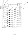
- the only figure 1 shows a block diagram of a charging system on which the method according to the invention can be carried out.
- the system 10 shown comprises a power grid connection 15 with a plurality of phases 14, for example a first phase 11, a second phase 12 and a third phase 13, to which electrical consumers, for example electric vehicles 16, hereinafter referred to as electric vehicle 16, are connected for charging the electric vehicles 16 can become.
- the electric vehicles 16 are each connected to a sub-distribution 17 via a charging point 19 .
- a control device 18 is provided, which monitors the system 10 .
- a phase current measuring device 20 is provided for each phase 11, 12, 13, 14, which transmits the values of the measured phase currents to the control device 18.
- Data connections 22 are preferably provided for the transmission of the values of the measured phase currents.
- data connections 22 is provided between the control device 18 and the electric vehicles 16, via which a performance specification can be transmitted from the control device 18 to the electric vehicles 16.
- phase current measuring device 20 data from a networked electricity meter can also be evaluated in order to draw conclusions about the phase currents.
- the control device 18 controls the electric vehicles 16 in such a way that the currents drawn from the electric vehicles 16 via the individual phases 11, 12, 13, 14 are such that the individual phases 11, 12, 13, 14 are loaded within predetermined operating parameters.
- These operating parameters include in particular a maximum power or a maximum phase current of the phases 11, 12, 13, 14.
- the operating parameters can also include a maximum unbalanced load between the phases 11, 12, 13, 14.
- the unbalanced load is defined by the greatest difference in the services that are called up over phases 11, 12, 13, 14.
- the unbalanced load is the load difference between the load of phase 11, 12, 13, 14, through which the greatest power is delivered, and the load of phase 11, 12, 13, 14, through which the lowest power is delivered.
- the load or the unbalanced load can be defined, for example, via the electrical power or the electrical current.
- the control device determines the maximum available charging power for the motor vehicle 16 and transmits this currently maximum available charging power to this motor vehicle 16. The motor vehicle 16 will then draw a maximum of this charging power via phase 11, 12, 13, 14. As the charging process continues, the control device 18 will continuously monitor the phase currents of the individual phases 11, 12, 13, 14 and, if necessary, output specifications transmit the motor vehicles 16, which signal the motor vehicles 16 that either more charging power may be retrieved, or that the charging power must be reduced.
- the maximum available charging power is given by the maximum unbalanced load.
- the maximum permitted unbalanced load is usually 20 amperes. It follows that the electric vehicle 16 can only charge with 20 amps.
- the phase currents are continuously monitored even when three electric vehicles 16 are connected, in order to be able to throttle the charging currents of individual electric vehicles 16, if necessary, in order to prevent the maximum permissible unbalanced load from being exceeded.
- the power specification is regularly used changed at a loading point 19.
- the phase currents at balance point 24 are observed. If the change in phase current matches the change in power specification, the electric vehicle 16 has charged with the full charge current according to the power specification.
- the change in the performance specification is repeated for each charging point 19 after a repetition time interval. As a result, the assessment of the regulatory potential remains up-to-date.
Landscapes
- Engineering & Computer Science (AREA)
- Power Engineering (AREA)
- Transportation (AREA)
- Mechanical Engineering (AREA)
- Charge And Discharge Circuits For Batteries Or The Like (AREA)
- Supply And Distribution Of Alternating Current (AREA)
Description
Die Erfindung betrifft ein Verfahren zum Betreiben eines Ladesystems mit mehreren Ladepunkten zum Laden von elektrischen Verbrauchern, bspw. von Elektrofahrzeugen, wobei das Ladesystem an einem Stromnetz mit mehreren Phasen angeschlossen ist.The invention relates to a method for operating a charging system with a number of charging points for charging electrical consumers, for example electric vehicles, the charging system being connected to a power grid with a number of phases.
Elektrofahrzeuge laden heutzutage ein- oder mehrphasig mit Wechselstrom oder mit Gleichstrom. Die Ladung mit Wechselstrom ist dabei nach Norm im Betrieb von 6 bis 63 Ampere auf einer oder mehreren Phasen möglich. Viele Energieversorgungsunternehmen und Verteilernetzbetreiber fordern eine Vermeidung von Schieflast über 20 Ampere durch einzelne Verbraucher. Es sind jedoch Elektrofahrzeuge auf dem Markt, welche einphasig über 20 Ampere laden. Dadurch kann allerdings eine Schieflast entstehen, die über der von den Energieversorgungsunternehmen und Verteilnetzbetreibern vorgegebenen maximalen Schieflast liegt. Um eine Schieflast zu vermeiden, können den Verbrauchern Leistungsvorgaben übermittelt werden, die angeben, wie hoch der maximale verfügbare Ladestrom für den jeweiligen Verbraucher ist, um die Last möglichst gleichmäßig auf die Phasen zu verteilen. Allerdings kann das Problem auftreten, dass ein Verbraucher nicht den gesamten verfügbaren Ladestrom abruft, beispielsweise, wenn dies durch den Laderegler des Verbrauchers grundsätzlich begrenzt ist, durch Nutzervorgabe reduziert ist oder wenn der Akku voll ist. Dies kann die Regelung der Schieflast beeinflussen.Electric vehicles nowadays charge in single or multi-phase alternating current or direct current. According to the standard, charging with alternating current is possible in operation from 6 to 63 amperes on one or more phases. Many energy supply companies and distribution network operators require that unbalanced loads of more than 20 amperes from individual consumers be avoided. However, there are electric vehicles on the market that charge over 20 amps in a single phase. However, this can result in an unbalanced load that is above the maximum unbalanced load specified by the energy supply companies and distribution network operators. In order to avoid an unbalanced load, the consumers can be given power specifications that indicate how high the maximum available charging current is for the respective consumer in order to distribute the load as evenly as possible over the phases. However, the problem can arise that a consumer does not call up the entire available charging current, for example if this is fundamentally limited by the consumer's charge controller, is reduced by user specifications or if the battery is full. This can affect the regulation of the unbalanced load.
Problematisch ist dies insbesondere, wenn die Übermittlung der Leistungsvorgaben nur in eine Richtung funktioniert, so dass die Verbraucher keine Rückmeldung über den tatsächlichen Ladestrom geben können.This is particularly problematic if the power specifications are only transmitted in one direction, so that the consumers cannot give any feedback about the actual charging current.
Die Dokumente
Der Erfindung liegt die Aufgabe zugrunde eine verbesserte oder zumindest andere Ausführungsform eines Verfahrens zum Betreiben eines Ladesystems mit mehreren Ladepunkten bereit zu stellen, die sich insbesondere durch die Vermeidung von zu hohen Schieflasten auszeichnet.The object of the invention is to provide an improved or at least different embodiment of a method for operating a charging system with a plurality of charging points, which is characterized in particular by the avoidance of unbalanced loads that are too high.
Diese Aufgabe wird erfindungsgemäß durch den Gegenstand des unabhängigen Anspruchs gelöst. Vorteilhafte Weiterbildungen sind Gegenstand der abhängigen Ansprüche.According to the invention, this object is achieved by the subject matter of the independent claim. Advantageous developments are the subject of the dependent claims.
Die Erfindung basiert auf der Grundidee, durch Änderung der Leistungsvorgabe an einzelnen Ladepunkten darauf zu schließen, wie hoch der Ladestrom des Verbrauchers an diesem Ladepunkt ist und wie hoch er sein könnte. Erfindungsgemäß ist daher vorgesehen, dass regelmäßig für jeden Ladepunkt einzeln die Leistungsvorgabe für ein vorgegebenes Testzeitintervall geändert wird und die resultierende Änderung der Phasenströme am Bilanzpunkt gemessen wird, und dass aus der resultierenden Änderung der Phasenströme ermittelt wird, ob an dem Ladepunkt noch ein solcher Verbraucher angeschlossen ist, ob der Verbraucher mit signifikantem Strom lädt und/oder oder der Verbraucher mit einem höherem Strom laden könnte. Dadurch kann eine Steuerung des Ladesystems erkennen, ob durch den Verbraucher an diesem Ladepunkt ein Regelpotential zur Vermeidung von Schieflast vorliegt oder nicht. Nur wenn ein signifikanter Ladestrom vorhanden ist und/oder wenn der Ladestrom erhöht werden kann, folgt der Ladestrom des Verbrauchers den Leistungsvorgaben. Daher ist es nur dann möglich durch die Änderung der Leistungsvorgabe die Schieflast zu beeinflussen. Daher ist diese Information wertvoll für die Regelung der Schieflast.The invention is based on the basic idea of inferring how high the charging current of the consumer is at this charging point and how high it could be by changing the power specification at individual charging points. According to the invention, it is therefore provided that the power specification for a predetermined test time interval is changed regularly for each charging point individually and the resulting change in the phase currents at the balance point is measured, and that the resulting change in the phase currents is used to determine whether such a consumer is still connected to the charging point is whether the load is charging with significant current and/or the load could charge with a higher current. As a result, a controller of the charging system can recognize whether or not there is a control potential for avoiding unbalanced loads due to the consumer at this charging point. Only when there is a significant charging current and/or when the charging current can be increased will the load's charging current follow the power specifications. It is therefore only possible to influence the unbalanced load by changing the performance specification. This information is therefore valuable for regulating the unbalanced load.
Das Testzeitintervall ist vorzugsweise ein kurzer Zeitraum, beispielsweise 5 bis 30 Sekunden.The test time interval is preferably a short period of time, for example 5 to 30 seconds.
Eine zweckmäßige Lösung sieht vor, dass an jedem Ladepunkt die Änderung der Leistungsvorgabe nach einem vorgegebenen Wiederholungszeitintervall wiederholt wird. Dadurch bleibt die Bewertung des Regelpotentials der einzelnen Verbraucher aktuell. Eine vorteilhafte Zeitspanne für die Wiederholung der Messung sind zum Beispiel 120 - 600 Sekunden.An expedient solution provides that the change in the power specification is repeated at each charging point after a predetermined repetition time interval. As a result, the evaluation of the control potential of the individual consumers remains up to date. An advantageous period of time for repeating the measurement is 120-600 seconds, for example.
Eine zweckmäßige Möglichkeit sieht vor, dass die Leistungsvorgabe für das vorgegebene Testzeitintervall verringert wird. Dadurch kann insbesondere erkannt werden, ob der Verbraucher mit einem signifikanten Ladestrom lädt oder nicht. Eine solche Änderung der Leistungsvorgabe kann beispielsweise eine Reduktion des Ladestroms vom 20A auf 10A sein. Reduziert sich dadurch der entsprechende Phasenstrom ebenfalls um 10A, heißt das, dass der Verbraucher mit 20A geladen hat und potentiell auch wieder laden wird, sobald die Leistungsvorgabe auf den alten Wert zurückgesetzt wird. Wenn allerdings keine oder nur eine kleine Änderung des Phasenstroms auftritt, heißt das, dass der Verbraucher nicht mit den vollen 20A geladen hat. Daher kann dieser Verbraucher nicht oder nur in geringerem Maße zur Regelung der Schieflast genutzt werden.An expedient possibility provides that the power specification for the specified test time interval is reduced. This makes it possible to identify in particular whether the consumer is charging with a significant charging current or not. Such a change in the power specification can be, for example, a reduction in the charging current from 20A to 10A. If this also reduces the corresponding phase current by 10A, this means that the consumer has charged with 20A and will potentially charge again as soon as the power specification is reset to the old value. However, if there is no or only a small change in the phase current, this means that the consumer has not charged the full 20A. This consumer can therefore not be used, or only to a lesser extent, to regulate the unbalanced load.
Eine weitere zweckmäßige Lösung sieht vor, dass die Leistungsvorgabe für das vorgegebene Testzeitintervall erhöht wird. Durch eine Erhöhung der Leistungsvorgabe kann entsprechend erkannt werden, ob der Verbraucher auch einen größeren Ladestrom nutzen würde. Somit kann das Regelpotential der einzelnen Verbraucher bestimmt werden.Another expedient solution provides that the power specification for the specified test time interval is increased. By increasing the power specification, it can be recognized accordingly whether the consumer would also use a larger charging current. In this way, the control potential of the individual consumers can be determined.
Eine weitere zweckmäßige Möglichkeit sieht vor, dass eine Schieflast der Phasen unterhalb eines Schieflastgrenzwertes gehalten wird, indem jedem zum Laden angeschlossenen elektrischen Verbraucher eine Leistungsvorgabe übermittelt wird. Dadurch besteht eine Regelungsmöglichkeit für die Phasenströme, sodass die Schieflast unterhalb des Schieflastgrenzwertes gehalten werden kann. Gleichzeitig kann, wenn an allen Phasen ein elektrischer Verbraucher zum Laden angeschlossen ist, ein höherer individueller Ladestrom erreicht werden, als bei einem Verfahren, in welchem die maximalen Ladeströme auf einen Grenzwert gedrosselt werden, bei welchem die Schieflastgrenze nicht überschritten werden kann. Der Schieflastgrenzwert ist üblicherweise durch das Energieversorgungsunternehmen oder den Verteilernetzbetreiber vorgegeben. Der Schieflastgrenzwert liegt bspw. bei 20 Ampere.A further expedient possibility provides that an unbalanced load of the phases is kept below an unbalanced load limit value by transmitting a power specification to each electrical consumer connected for charging. This allows the phase currents to be regulated so that the unbalanced load can be kept below the unbalanced load limit value. At the same time, if an electrical load is connected to all phases for charging is, a higher individual charging current can be achieved than with a method in which the maximum charging currents are throttled to a limit value at which the unbalanced load limit cannot be exceeded. The unbalanced load limit is usually specified by the energy supply company or the distribution network operator. The unbalanced load limit is 20 amps, for example.
In der Beschreibung und den beigefügten Ansprüchen wird unter der Schieflast die aktuell größte auftretende Differenz der Lasten zwischen jeweils zwei beliebigen Phasen des Stromnetzes an dem Bilanzpunkt verstanden.In the description and the appended claims, the unbalanced load is understood to mean the currently largest occurring difference in the loads between any two phases of the power grid at the balance point.
Eine günstige Möglichkeit sieht vor, dass die Leistungsvorgaben für die elektrischen Verbraucher derart eingestellt werden, dass jede Lastdifferenz zwischen jedem möglichen Paar der Phasen des Stromnetzes am Bilanzpunkt kleiner als der Schieflastgrenzwert ist. Dadurch kann erreicht werden, dass die Schieflast unterhalb des Schieflastgrenzwertes bleibt.A favorable option provides that the power specifications for the electrical consumers are set in such a way that every load difference between every possible pair of phases of the power grid at the balance point is smaller than the unbalanced load limit value. This can ensure that the unbalanced load remains below the unbalanced load limit value.
In der Beschreibung und den beigefügten Ansprüchen wird unter einem Bilanzpunkt ein Punkt des Stromnetzes verstanden, an welchen die Schieflastgrenze eingehalten werden soll. Ein solcher Bilanzpunkt kann bspw. ein elektrischer Hausanschluss, der Ausgang eines Mittelspannungstransformators oder ein virtuelles Energieversorgungsnetz sein.In the description and the appended claims, a balance point is understood to mean a point in the power grid at which the unbalanced load limit is to be complied with. Such a balance point can be, for example, an electrical house connection, the output of a medium-voltage transformer or a virtual energy supply network.
Eine weitere günstige Möglichkeit sieht vor, dass die Leistungsvorgabe umfasst, wie viel Ladeleistung aktuell zusätzlich entnommen werden darf, oder um wie viel die Ladeleistung reduziert werden muss. Dadurch können über die Leistungsvorgabe die Phasenströme geregelt werden, sodass angeschlossenen elektrischen Verbrauchern die größtmögliche elektrische Ladeleistung zur Verfügung gestellt werden kann, ohne dass die Schieflast den Schieflastgrenzwert überschreitet. Eine weitere besonders günstige Möglichkeit sieht vor, dass, wenn der Phasenstrom einer Phase unterhalb eines Lastgrenzwertes liegt und der Phasenstrom dieser Phase kleiner ist als der geringste gemessene Phasenstrom einer anderen Phase zuzüglich des Schieflastgrenzwertes, wird über die Leistungsvorgabe signalisiert, dass zusätzliche Ladeleistung entnommen werden darf. Dadurch kann erreicht werden, dass wenn Leistungsreserven vorhanden sind, diese Leistungsreserven durch den angeschlossenen elektrischen Verbraucher auch ausgenutzt werden können. Die Höhe der zusätzlichen Leistung ergibt sich durch den Abstand zu den jeweiligen Grenzwerten, wobei der kleinere der beiden Abstände zu den Grenzwerten relevant ist für die mögliche Leistungserhöhung.A further favorable possibility provides that the power specification includes how much additional charging power may currently be drawn, or by how much the charging power must be reduced. As a result, the phase currents can be regulated via the power specification, so that connected electrical consumers can be provided with the greatest possible electrical charging power without the unbalanced load exceeding the unbalanced load limit value. Another particularly favorable possibility provides that if the phase current of a phase is below a load limit value and the phase current of this phase is smaller than the lowest measured phase current of another phase plus the unbalanced load limit value, the power specification signals that additional charging power may be drawn . As a result, if power reserves are available, these power reserves can also be utilized by the connected electrical consumer. The amount of additional power results from the distance to the respective limit values, with the smaller of the two distances to the limit values being relevant for the possible increase in power.
Ferner sieht die besonders günstige Möglichkeit vor, dass, wenn der Phasenstrom einer Phase oberhalb eines Lastgrenzwertes liegt oder der Phasenstrom dieser Phase größer ist als der geringste gemessene Phasenstrom einer der anderen Phasen zuzüglich des Schieflastgrenzwertes, wird über die Leistungsvorgabe signalisiert, dass die Ladeleistung reduziert werden muss. Dadurch kann auf Laständerungen an dem Stromnetz reagiert werden, um eine Überlastung oder ein Überschreiten des Schieflastgrenzwertes zu verhindern. Die Höhe der zu reduzierenden Leistung ergibt sich durch die jeweilige Überschreitung des Lastgrenzwertes bzw. des Schieflastgrenzwertes, wobei bei Überschreitung beider Grenzwerte der höhere Wert relevant ist, sodass nach der durchgeführten Reduktion der Ladeleistung beide Grenzwerte eingehalten werden.Furthermore, the particularly favorable possibility provides that if the phase current of a phase is above a load limit value or the phase current of this phase is greater than the lowest measured phase current of one of the other phases plus the unbalanced load limit value, the power specification signals that the charging power is to be reduced got to. As a result, it is possible to react to load changes on the power grid in order to prevent overloading or the unbalanced load limit being exceeded. The amount of power to be reduced results from the respective exceeding of the load limit value or the unbalanced load limit value, whereby if both limit values are exceeded, the higher value is relevant, so that after the reduction in charging power has been carried out, both limit values are complied with.
Eine vorteilhafte Lösung sieht vor, dass die Leistungsvorgabe eine aktuell maximale verfügbare Ladeleistung umfasst. Die Leistungsvorgabe kann dem angeschlossenen elektrischen Verbraucher damit signalisieren, wie viel maximal verfügbare Ladeleistung bereit steht, bspw. wenn der elektrische Verbraucher gerade angeschlossen wurde. Dadurch kann die Regelzeit, bis die optimale Ladeleistung eingestellt ist, verkürzt werden.An advantageous solution provides that the power specification includes a currently maximum available charging power. The power specification can thus signal to the connected electrical consumer how much maximum available charging power is available, for example when the electrical consumer has just been connected. As a result, the control time until the optimal charging capacity is set can be shortened.
Eine weitere vorteilhafte Lösung sieht vor, dass die aktuell maximale verfügbare Ladeleistung der Phase unter Berücksichtigung zumindest der aktuellen Phasenströme, einer maximalen zulässigen Leistung der jeweiligen Phase und einer maximal zulässigen Schieflast zwischen den Phasen ermittelt wird. Dadurch kann bei der Bestimmung der maximal verfügbaren Ladeleistung sichergestellt werden, dass die Phase des Stromnetzes nicht überlastet wird und dass die Schieflast den Schieflastgrenzwert nicht überschreitet.A further advantageous solution provides that the currently maximum available charging power of the phase is determined taking into account at least the current phase currents, a maximum permissible power of the respective phase and a maximum permissible unbalanced load between the phases. In this way, when determining the maximum available charging power, it can be ensured that the phase of the power grid is not overloaded and that the unbalanced load does not exceed the unbalanced load limit value.
Eine zweckmäßige Variante sieht vor, dass, wenn ein elektrischer Verbraucher zum Laden angeschlossen wird, ermittelt wird, an welcher Phase der elektrische Verbraucher angeschlossen ist, und eine aktuell maximal verfügbare Ladeleistung der Phase, an der der elektrische Verbraucher angeschlossen ist, ermittelt wird, und dem elektrischen Verbraucher die aktuell maximale verfügbare Ladeleistung übermittelt wird. Wenn also der elektrische Verbraucher angeschlossen wird, erhält dieser die Information, wie viel Leistung er zum Laden über die Phase entnehmen darf. Dadurch wird in besonders kurzer Zeit die optimale Ausnutzung des Stromnetzes erreicht.An expedient variant provides that, when an electrical consumer is connected for charging, it is determined to which phase the electrical consumer is connected, and a currently maximum available charging power of the phase to which the electrical consumer is connected is determined, and the current maximum available charging power is transmitted to the electrical consumer. So when the electrical consumer is connected, it receives information about how much power it can use for charging via the phase. As a result, optimal utilization of the power grid is achieved in a particularly short time.
Eine weitere zweckmäßige Variante sieht vor, dass die Leistungsvorgaben derart gewählt werden, dass zusätzlich eine individuelle Last der einzelnen Phasen jeweils unterhalb eines Lastgrenzwertes gehalten wird. Dadurch wird die Überlastung der einzelnen Phasen des Stromnetzes verhindert, sodass ein sicherer und stabiler Betrieb ermöglicht wird. Vorteilhaft ist der Lastgrenzwert durch eine maximal zulässige Last am Bilanzpunkt gegeben.A further expedient variant provides that the power specifications are selected in such a way that an individual load of the individual phases is also kept below a load limit value. This prevents overloading of the individual phases of the power grid, enabling safe and stable operation. The load limit value is advantageously given by a maximum permissible load at the balance point.
Eine vorteilhafte Möglichkeit sieht vor, dass die Phasenströme am Bilanzpunkt fortlaufend ermittelt werden, und daraus fortlaufend die Leistungsvorgabe für die zum Laden angeschlossenen elektrischen Verbraucher angepasst und dem jeweiligen elektrischen Verbraucher übermittelt werden. Dadurch kann auf Änderungen der Lastbedingungen an den einzelnen Phasen reagiert werden. Insbesondere kann, wenn bspw. an der ersten Phase die Ladung des elektrischen Verbrauchers beendet wird und keine Leistung mehr entnommen wird, es zu einer Schieflast führen, wenn an den anderen Phasen elektrische Verbraucher hängen. Durch die fortlaufende Überwachung kann dies erkannt werden und somit die übrigen elektrischen Verbraucher in ihrer Ladeleistung gedrosselt werden, sodass der Schieflastgrenzwert nicht überschritten wird.An advantageous possibility provides that the phase currents at the balance point are continuously determined, and from this the power specification for the electrical consumers connected for charging is continuously adapted and transmitted to the respective electrical consumer. This allows for changes of the load conditions on the individual phases can be reacted to. In particular, if, for example, the charging of the electrical consumer is terminated in the first phase and no more power is drawn, this can lead to an unbalanced load if electrical consumers are connected to the other phases. This can be detected through continuous monitoring and the charging power of the other electrical consumers can be throttled so that the unbalanced load limit is not exceeded.
Eine weitere vorteilhafte Möglichkeit sieht vor, dass das Stromnetz ein dreiphasiges Drehstromnetz ist. Solche dreiphasigen Drehstromnetze werden üblicherweise von den Energieversorgungsunternehmen bereitgestellt.A further advantageous possibility provides that the power grid is a three-phase power grid. Such three-phase AC networks are usually provided by the energy supply companies.
Eine günstige Variante sieht vor, dass die elektrischen Verbraucher anhand der übermittelten Leistungsvorgaben die abgerufene Ladeleistung einstellen. Dadurch wird erreicht, dass tatsächlich eine Regelung der Ladeleistung erfolgt, sodass die Leistungsgrenzwerte und die Schieflastgrenzwerte eingehalten werden können. Es versteht sich, dass die elektrischen Verbraucher nicht zwingend die maximal zur Verfügung stehende Ladeleistung abrufen müssen.A favorable variant envisages that the electrical consumers set the required charging power based on the transmitted power specifications. This ensures that the charging power is actually regulated so that the power limit values and the unbalanced load limit values can be complied with. It goes without saying that the electrical consumers do not necessarily have to call up the maximum available charging power.
Eine weitere günstige Variante sieht vor, dass die Leistungsvorgaben durch ein PWM-Signal übermittelt werden. Solche PWM-Signale sind leicht zu erzeugen und leicht zu interpretieren, so dass dadurch eine sehr einfache Übermittlung der Leistungsvorgaben möglich ist.Another favorable variant provides that the performance specifications are transmitted by a PWM signal. Such PWM signals are easy to generate and easy to interpret, so that a very simple transmission of the performance specifications is possible.
Eine besonders vorteilhafte Lösung sieht vor, dass die zum Laden angeschlossenen elektrischen Verbraucher Elektrofahrzeuge sind. Gerade bei Elektrofahrzeugen treten sehr hohe Ladeleistungen auf, um die Ladezeit der Elektrofahrzeuge zu verkürzen, sodass die Problematik der Schieflast und der Überlastung einzelner Phasen besonders relevant ist.A particularly advantageous solution provides that the electrical loads connected for charging are electric vehicles. Especially with electric vehicles, very high charging powers occur in order to shorten the charging time of the electric vehicles, so that the problem of unbalanced loads and overloading of individual phases is particularly relevant.
In der Beschreibung und den beigefügten Ansprüchen werden unter Elektrofahrzeuge Kraftfahrzeuge verstanden, die zumindest teilweise durch einen Elektroantrieb angetrieben sind und einen elektrischen Energiespeicher aufweisen.In the description and the appended claims, electric vehicles are motor vehicles that are at least partially driven by an electric drive and have an electrical energy store.
Weitere wichtige Merkmale und Vorteile der Erfindung ergeben sich aus den Unteransprüchen, aus der Zeichnung und aus der zugehörigen Figurenbeschreibung anhand der Zeichnung.Further important features and advantages of the invention result from the dependent claims, from the drawing and from the associated description of the figures based on the drawing.
Es versteht sich, dass die vorstehend genannten und die nachstehend noch zu erläuternden Merkmale nicht nur in der jeweils angegebenen Kombination, sondern auch in anderen Kombinationen oder in Alleinstellung verwendbar sind, ohne den Rahmen der vorliegenden Erfindung zu verlassen.It goes without saying that the features mentioned above and those still to be explained below can be used not only in the combination specified in each case, but also in other combinations or on their own, without departing from the scope of the present invention.
Bevorzugte Ausführungsbeispiele der Erfindung sind in der Zeichnung dargestellt und werden in der nachfolgenden Beschreibung näher erläutert.Preferred embodiments of the invention are shown in the drawing and are explained in more detail in the following description.
Die einzige
Ein in
Alternativ zur Phasenstrommesseinrichtung 20 können auch Daten eines vernetzten Stromzählers ausgewertet werden, um auf die Phasenströme zu schließen.As an alternative to the phase
Die Steuereinrichtung 18 steuert die Elektrofahrzeuge 16 derart an, dass die von den Elektrofahrzeugen 16 über die einzelnen Phasen 11, 12, 13, 14 entnommenen Ströme derart sind, dass die einzelnen Phasen 11, 12, 13, 14 innerhalb vorgegebener Betriebsparameter belastet werden.The
Diese Betriebsparameter umfassen insbesondere eine maximale Leistung bzw. einen maximalen Phasenstrom der Phasen 11, 12, 13, 14. Des Weiteren können die Betriebsparameter auch eine maximale Schieflast zwischen den Phasen 11, 12, 13, 14 umfassen. Die Schieflast definiert sich durch den größten Unterschied der Leistungen, die über die Phasen 11, 12, 13, 14 abgerufen werden. Insbesondere ist die Schieflast die Lastdifferenz zwischen der Last der Phase 11, 12, 13, 14, über welche die größte Leistung abgegeben wird zu der Last der Phase 11, 12, 13, 14 über die die geringste Leistung abgegeben wird. Die Last bzw. die Schieflast kann dabei beispielsweise über die elektrische Leistung oder den elektrischen Strom definiert werden.These operating parameters include in particular a maximum power or a maximum phase current of the
Wird nun ein Kraftfahrzeug 16 zum Laden an eine der Phasen 11, 12, 13, 14 angeschlossen, ermittelt die Steuerungseinrichtung, wie hoch die maximal verfügbare Ladeleistung für das Kraftfahrzeug 16 ist und übermittelt diese aktuell maximale verfügbare Ladeleistung an dieses Kraftfahrzeug 16. Das Kraftfahrzeug 16 wird dann maximal diese Ladeleistung über die Phase 11, 12, 13, 14 beziehen. Im weiteren Ladevorgang wird die Steuereinrichtung 18 fortlaufend die Phasenströme der einzelnen Phasen 11, 12, 13, 14 überwachen und ggf. Leistungsvorgaben an die Kraftfahrzeuge 16 übermitteln, welche den Kraftfahrzeugen 16 signalisieren, dass entweder mehr Ladeleistung abgerufen werden darf, oder dass die Ladeleistung reduziert werden muss.If a
Wenn bspw. nur ein einzelnes Elektrofahrzeug 16 an einer der Phasen 11, 12, 13, 14 angeschlossen ist, ist die maximal verfügbare Ladeleistung durch die maximale Schieflast gegeben. Die maximale erlaubte Schieflast beträgt üblicherweise 20 Ampere. Daraus ergibt sich, dass das Elektrofahrzeug 16 lediglich mit 20 Ampere laden kann.If, for example, only a single
Falls ein zweites Elektrofahrzeug 16 an eine weitere Phase 11, 12, 13, 14 angeschlossen wird, kann dieses ebenfalls mit 20 Ampere geladen werden. Wenn schließlich auch an einer dritten Phase 11, 12, 13, 14 ein Elektrofahrzeug 16 angeschlossen wird, ergibt sich somit ein Lastausgleich, wodurch die maximale Ladeleistung nicht mehr durch die Schieflast begrenzt wird, sondern durch die individuelle maximale Last an den einzelnen Phasen 11, 12, 13, 14.If a second
Da die Ladeleistung der Elektrofahrzeuge 16 nicht notwendiger Weise immer die maximal verfügbare Ladeleistung ist, erfolgt auch bei drei angeschlossenen Elektrofahrzeugen 16 eine fortlaufende Überwachung der Phasenströme, um ggf. Ladeströme einzelner Elektrofahrzeuge 16 drosseln zu können, um eine Überschreitung der maximal zulässigen Schieflast zu verhindern.Since the charging power of the
Es versteht sich, dass auch mehr als ein Elektrofahrzeug 16 zum Laden an einer einzelnen Phase 11, 12,13, 14 angeschlossen sein kann. Somit können mehr Elektrofahrzeuge 16 gleichzeitig geladen werden, als Phasen 11, 12, 13, 14 am Stromnetz zur Verfügung stehen.It goes without saying that more than one
Um zu ermitteln, wie hoch der von den jeweiligen angeschlossenen Elektrofahrzeuge 16 bezogene Ladestrom oder Ladeleistung ist, wird regelmäßig die Leistungsvorgabe an einem Ladepunkt 19 geändert. Dabei werden die Phasenströme am Bilanzpunkt 24 beobachtet. Wenn die Änderung des Phasenstroms der Änderung der Leistungsvorgabe entspricht, hat das Elektrofahrzeug 16 mit dem vollen Ladestrom nach der Leistungsvorgabe geladen.In order to determine how high the charging current or charging power drawn from the respective connected
Wenn allerdings die Änderung des Phasenstroms nicht der Änderung der Leistungsvorgabe entspricht, hat das Elektrofahrzeug 16 mit einem kleineren Ladestrom geladen. Das bedeutet, dass die Steuereinrichtung 18 berücksichtigen muss, dass das an diesem Ladepunkt 19 angeschlossene Elektrofahrzeug 16 nicht den maximalen Ladestrom abrufen wird. Entsprechend müssen die Leistungsvorgaben für die anderen Ladepunkte 19 geändert werden, um die Schieflast innerhalb der zulässigen Grenzen zu halten.However, if the change in phase current does not match the change in power specification, the
Durch eine Reduktion der Leistungsvorgabe kann also erkannt werden, wie hoch der Ladestrom des Elektrofahrzeugs 16 ist, bzw. ob das Elektrofahrzeug 16 seinen Ladevorgang beendet hat. Durch eine Erhöhung der Leistungsvorgabe kann erkannt werden, ob das jeweilige angeschlossene Elektrofahrzeug 16 einen größeren Ladestrom beziehen würde und somit eine weitere Regelung der Schieflast ermöglicht. Somit kann das Regelungspotential für die Schieflast der einzelnen Elektrofahrzeuge 16 ermittelt werden.By reducing the power specification, it is thus possible to identify how high the charging current of the
Die Änderung der Leistungsvorgabe wird für jeden Ladepunkt 19 nach einem Wiederholungszeitintervall wiederholt. Dadurch bleibt die Beurteilung der Regelungspotentiale aktuell.The change in the performance specification is repeated for each charging
Claims (13)
- Method for operating a charging system (10) with multiple charging points (19) for charging electrical consumers (16), for example electric vehicles,- wherein the charging system (10) is connected to a power grid having multiple phases (11, 12, 13, 14),- wherein phase currents of the phases (11, 12, 13, 14) of the power grid are measured at a balance point (24),- wherein power specifications are transmitted to electrical consumers (16) connected to one of the charging points (19),- wherein, for each charging point (19) individually, the power specification is changed regularly for a predefined test time interval and the resulting change of the phase currents is measured at the balance point (24), and
that it is determined from the resulting change in the phase currents whether such a consumer (16) is still connected to the charging point (19), whether the consumer (16) is charging with a significant current and/or whether the consumer (16) could charge with a higher current,- wherein at each charging point (19) the change in power specification is repeated after a predefined repetition time interval,characterised in that- each charging point (19) is connected to exactly one phase (11, 12, 13) of the phases (11, 12, 13). - Method according to claim 1,
characterised in that
the power specification for the test time interval is increased or reduced. - Method according to any of claims 1 to 2,
characterised in that- an unbalanced load of the phases (11, 12, 13, 14) is kept below an unbalanced load limit value by transmitting an adapted power specification to each electrical consumer (16) connected for charging. - Method according to any of claims 1 to 3,
characterised in that
the power specification includes how much additional charging power may presently be withdrawn or by how much the charging power has to be reduced. - Method according to claim 4,
characterised in that- when the phase current of one phase (11, 12, 13, 14) is below a load limit value and the phase current of this phase (11, 12, 13, 14) is lower than the smallest measured phase current of one of the other phases (11, 12, 13, 14) plus the unbalanced load limit value, it is signaled via the power specification that additional charging power can be withdrawn,- when the phase current of one phase (11, 12, 13, 14) is above a load limit value or the phase current of this phase (11, 12, 13, 14) is greater than the smallest measured phase current of one of the other phases (11, 12, 13, 14) plus the unbalanced load limit value, it is signaled via the power specification that the charging power has to be reduced. - Method according to any of claims 1 to 5,
characterised in that
the power specification includes a present maximum available charging power. - Method according to claim 6,
characterised in that
the present maximum available charging power of the phase (11, 12, 13, 14) is determined taking into account at least the present phase currents, a maximum permissible power of the respective phase (11, 12, 13, 14) and a maximum permissible unbalanced load between the phases (11, 12, 13, 14). - Method according to claim 6 or 7,
characterised in that
when an electrical consumer (16) is connected for charging, it is determined to which phase (11, 12, 13, 14) the electrical consumer (16) is connected, and a present maximum available charging power of the phase (11, 12, 13, 14) to which the electrical consumer is connected is determined, and the present maximum available charging power is transmitted to the electrical consumer (16). - Method according to any of claims 1 to 8,
characterised in that
the power specifications are selected in such a way that, in addition, an individual load of the individual phases (11, 12, 13, 14) is in each case kept below a load limit value. - Method according to any of claims 1 to 9,
characterised in that
the phase currents at the balance point (24) are continuously determined, and based thereon the power specifications for the electrical consumers (16) connected for charging are continuously adapted and transmitted to the respective electrical consumer (16). - Method according to any of claims 1 to 10,
characterised in that
the electrical consumers (16) set the retrieved charging power on the basis of the transmitted power specifications. - Method according to any of claims 1 to 11,
characterised in that
the power specifications are transmitted by a PWM signal. - Method according to any of claims 1 to 12,
characterised in that
the electrical consumers (16) connected for charging are electric vehicles.
Applications Claiming Priority (1)
| Application Number | Priority Date | Filing Date | Title |
|---|---|---|---|
| DE102018208396.7A DE102018208396A1 (en) | 2018-05-28 | 2018-05-28 | Method for operating a charging system with several charging points |
Publications (2)
| Publication Number | Publication Date |
|---|---|
| EP3576246A1 EP3576246A1 (en) | 2019-12-04 |
| EP3576246B1 true EP3576246B1 (en) | 2023-01-04 |
Family
ID=66323757
Family Applications (1)
| Application Number | Title | Priority Date | Filing Date |
|---|---|---|---|
| EP19171592.9A Active EP3576246B1 (en) | 2018-05-28 | 2019-04-29 | Method for operating a loading system with multiple loading points |
Country Status (4)
| Country | Link |
|---|---|
| US (1) | US11631977B2 (en) |
| EP (1) | EP3576246B1 (en) |
| DE (1) | DE102018208396A1 (en) |
| ES (1) | ES2936615T3 (en) |
Families Citing this family (6)
| Publication number | Priority date | Publication date | Assignee | Title |
|---|---|---|---|---|
| DE202022105943U1 (en) | 2021-10-22 | 2022-10-31 | smopi® - Multi Chargepoint Solution GmbH | charging station |
| NO347232B1 (en) * | 2022-05-31 | 2023-07-17 | Defa As | An electric vehicle supply equipment, a method for customizing the charging pattern of batteries of an electric vehicle supply equipment and a system for customizing the charging pattern of batteries of an electric vehicle supply equipment |
| GB2628250A (en) * | 2022-06-13 | 2024-09-18 | 3Ti Energy Hubs Ltd | A controller |
| GB2619910B (en) * | 2022-06-13 | 2024-07-24 | 3Ti Energy Hubs Ltd | A controller |
| EP4336692A1 (en) * | 2022-09-12 | 2024-03-13 | ABB E-Mobility B.V. | Charging arrangement for balancing phase currents |
| US11890960B1 (en) * | 2022-12-29 | 2024-02-06 | Rivian Ip Holdings, Llc | Interface based electrical load management |
Citations (1)
| Publication number | Priority date | Publication date | Assignee | Title |
|---|---|---|---|---|
| US20130049677A1 (en) * | 2010-03-05 | 2013-02-28 | Abb B,V, | System, devices and method for charging a battery of an electric vehicle |
Family Cites Families (21)
| Publication number | Priority date | Publication date | Assignee | Title |
|---|---|---|---|---|
| CN1261319C (en) * | 2004-11-11 | 2006-06-28 | 北京电巴科技有限公司 | Electric public transport system |
| US7612466B2 (en) * | 2008-01-28 | 2009-11-03 | VPT Energy Systems | System and method for coordinated control and utilization of local storage and generation, with a power grid |
| US8315745B2 (en) * | 2009-04-24 | 2012-11-20 | Hunter Defense Technologies, Inc. | Mobile micro-grid power system controller and method |
| EP2385606B1 (en) * | 2010-05-03 | 2019-12-25 | Siemens Gamesa Renewable Energy A/S | System for interchanging electric energy between a battery and an electric grid and respective method. |
| US8594859B2 (en) * | 2010-10-18 | 2013-11-26 | Qualcomm Incorporated | Method and system for real-time aggregation of electric vehicle information for real-time auctioning of ancillary services, and real-time lowest cost matching electric vehicle energy demand to charging services |
| FR2971897B1 (en) * | 2011-02-18 | 2013-02-22 | Commissariat Energie Atomique | CHARGE BALANCING DEVICE ON A POLYPHASE NETWORK |
| US20120265459A1 (en) * | 2011-04-14 | 2012-10-18 | General Electric Company | Integrated electric meter and electric vehicle charging station (evcs) |
| US9281689B2 (en) * | 2011-06-08 | 2016-03-08 | General Electric Technology Gmbh | Load phase balancing at multiple tiers of a multi-tier hierarchical intelligent power distribution grid |
| CN104540706B (en) * | 2012-02-13 | 2018-02-06 | 埃森哲环球服务有限公司 | For electric power tracking and the method and system of the distributed intelligence of electric power distribution |
| WO2013159073A1 (en) | 2012-04-20 | 2013-10-24 | Pedia Solutions, Llc | Apparatus and methods for oral administration of fluids and medical instrumentation |
| FR2993514B1 (en) * | 2012-07-20 | 2015-12-04 | Schneider Electric Ind Sas | METHOD AND DEVICE FOR DISTRIBUTING ELECTRICAL ENERGY |
| WO2014027246A2 (en) * | 2012-08-16 | 2014-02-20 | Robert Bosch Gmbh | Dc building system with energy storage and control system |
| US9562935B2 (en) * | 2012-10-19 | 2017-02-07 | Lear Corporation | Apparatus and method for detecting a phase sequence in a vehicle |
| DE102012221473A1 (en) * | 2012-11-23 | 2014-05-28 | Thomas Bichler | Method for charging a traction battery |
| EP2806520A1 (en) * | 2013-05-22 | 2014-11-26 | Vito NV | Power supply network control system and method |
| CN203772983U (en) * | 2014-03-07 | 2014-08-13 | 国家电网公司 | Test platform for low-voltage distribution imbalance compensation apparatus |
| DE102014003250A1 (en) * | 2014-03-12 | 2015-09-17 | Rwe Deutschland Ag | Method for operating an electrical subscriber, an electrical measuring point on a subscriber network and an electrical subscriber and an electrical measuring point |
| US9616763B2 (en) * | 2014-06-12 | 2017-04-11 | King Fahd University Of Petroleum And Minerals | Autonomous charging management system for electric vehicles |
| US9461707B1 (en) * | 2015-05-21 | 2016-10-04 | Landis+Gyr Technologies, Llc | Power-line network with multi-scheme communication |
| US20170271984A1 (en) * | 2016-03-04 | 2017-09-21 | Atigeo Corp. | Using battery dc characteristics to control power output |
| US20180123391A1 (en) * | 2016-10-28 | 2018-05-03 | Totem Power, Inc. | System and Method for Dynamic Measurement and Control of Synchronized Remote Energy Resources |
-
2018
- 2018-05-28 DE DE102018208396.7A patent/DE102018208396A1/en active Pending
-
2019
- 2019-04-29 ES ES19171592T patent/ES2936615T3/en active Active
- 2019-04-29 EP EP19171592.9A patent/EP3576246B1/en active Active
- 2019-05-24 US US16/422,402 patent/US11631977B2/en active Active
Patent Citations (1)
| Publication number | Priority date | Publication date | Assignee | Title |
|---|---|---|---|---|
| US20130049677A1 (en) * | 2010-03-05 | 2013-02-28 | Abb B,V, | System, devices and method for charging a battery of an electric vehicle |
Also Published As
| Publication number | Publication date |
|---|---|
| EP3576246A1 (en) | 2019-12-04 |
| US20190359077A1 (en) | 2019-11-28 |
| DE102018208396A1 (en) | 2019-11-28 |
| US11631977B2 (en) | 2023-04-18 |
| ES2936615T3 (en) | 2023-03-21 |
Similar Documents
| Publication | Publication Date | Title |
|---|---|---|
| EP3576246B1 (en) | Method for operating a loading system with multiple loading points | |
| EP3544145B1 (en) | Method for loading of electrical consumers | |
| DE102018106308B4 (en) | Modulation index improvement through intelligent battery | |
| EP2569840A2 (en) | Switching device | |
| EP3934931A1 (en) | Charging station for charging electric vehicles | |
| EP3566276A1 (en) | Method for operating a node on a supply grid | |
| EP3417523B1 (en) | Method for controlling a variable transformer and electrical system for coupling two ac networks | |
| EP2735468A2 (en) | Method for charging a traction battery | |
| DE112010006053T5 (en) | Charging device and method for controlling a charging device | |
| DE112019005307T5 (en) | Power supply system and power source forming it | |
| DE102018124124B3 (en) | Method and device for identifying an assignment of phase lines to terminals of an electrical equipment that can not withstand load | |
| WO2011157488A2 (en) | Device for grid voltage symmetrization | |
| DE102015105152A1 (en) | Arrangement and method for reducing unbalanced load in a three-phase distribution network | |
| EP2869072A1 (en) | Device and method for detecting electric energy from single or multiple phase consumers | |
| DE102017203852A1 (en) | Method for unbalanced load limiting and unbalanced load limiting unit | |
| EP3371847A1 (en) | Method for operating a battery, and battery | |
| WO2019166342A1 (en) | Device for connecting a sub-network to an alternating voltage network and method for controlling an electrical power | |
| DE112022002486T5 (en) | ADJUSTMENT OF INVERTER TERMINAL VOLTAGE IN POWER SYSTEM | |
| EP3123607B1 (en) | Modular converter system for an electric supply network | |
| DE212019000262U1 (en) | Performance equalization system | |
| EP3741022A1 (en) | Method and device for controlling a voltage | |
| DE102019121387A1 (en) | PROCEDURE AND UNIT FOR REDUCING A POWER REFERENCE DIFFERENCE | |
| DE102013113437A1 (en) | Method for calibrating an electrically driven vehicle to a network standard | |
| DE102017212785A1 (en) | Phase unbalance minimization | |
| EP3624290A1 (en) | Method and control device for operating an electrical power distribution network |
Legal Events
| Date | Code | Title | Description |
|---|---|---|---|
| PUAI | Public reference made under article 153(3) epc to a published international application that has entered the european phase |
Free format text: ORIGINAL CODE: 0009012 |
|
| STAA | Information on the status of an ep patent application or granted ep patent |
Free format text: STATUS: THE APPLICATION HAS BEEN PUBLISHED |
|
| AK | Designated contracting states |
Kind code of ref document: A1 Designated state(s): AL AT BE BG CH CY CZ DE DK EE ES FI FR GB GR HR HU IE IS IT LI LT LU LV MC MK MT NL NO PL PT RO RS SE SI SK SM TR |
|
| AX | Request for extension of the european patent |
Extension state: BA ME |
|
| STAA | Information on the status of an ep patent application or granted ep patent |
Free format text: STATUS: REQUEST FOR EXAMINATION WAS MADE |
|
| 17P | Request for examination filed |
Effective date: 20200311 |
|
| RBV | Designated contracting states (corrected) |
Designated state(s): AL AT BE BG CH CY CZ DE DK EE ES FI FR GB GR HR HU IE IS IT LI LT LU LV MC MK MT NL NO PL PT RO RS SE SI SK SM TR |
|
| STAA | Information on the status of an ep patent application or granted ep patent |
Free format text: STATUS: EXAMINATION IS IN PROGRESS |
|
| 17Q | First examination report despatched |
Effective date: 20200708 |
|
| STAA | Information on the status of an ep patent application or granted ep patent |
Free format text: STATUS: EXAMINATION IS IN PROGRESS |
|
| GRAP | Despatch of communication of intention to grant a patent |
Free format text: ORIGINAL CODE: EPIDOSNIGR1 |
|
| STAA | Information on the status of an ep patent application or granted ep patent |
Free format text: STATUS: GRANT OF PATENT IS INTENDED |
|
| INTG | Intention to grant announced |
Effective date: 20221014 |
|
| GRAS | Grant fee paid |
Free format text: ORIGINAL CODE: EPIDOSNIGR3 |
|
| GRAA | (expected) grant |
Free format text: ORIGINAL CODE: 0009210 |
|
| STAA | Information on the status of an ep patent application or granted ep patent |
Free format text: STATUS: THE PATENT HAS BEEN GRANTED |
|
| AK | Designated contracting states |
Kind code of ref document: B1 Designated state(s): AL AT BE BG CH CY CZ DE DK EE ES FI FR GB GR HR HU IE IS IT LI LT LU LV MC MK MT NL NO PL PT RO RS SE SI SK SM TR |
|
| REG | Reference to a national code |
Ref country code: GB Ref legal event code: FG4D Free format text: NOT ENGLISH |
|
| REG | Reference to a national code |
Ref country code: DE Ref legal event code: R096 Ref document number: 502019006674 Country of ref document: DE |
|
| REG | Reference to a national code |
Ref country code: CH Ref legal event code: EP |
|
| REG | Reference to a national code |
Ref country code: AT Ref legal event code: REF Ref document number: 1542627 Country of ref document: AT Kind code of ref document: T Effective date: 20230115 |
|
| REG | Reference to a national code |
Ref country code: IE Ref legal event code: FG4D Free format text: LANGUAGE OF EP DOCUMENT: GERMAN |
|
| REG | Reference to a national code |
Ref country code: ES Ref legal event code: FG2A Ref document number: 2936615 Country of ref document: ES Kind code of ref document: T3 Effective date: 20230321 |
|
| REG | Reference to a national code |
Ref country code: LT Ref legal event code: MG9D |
|
| REG | Reference to a national code |
Ref country code: NL Ref legal event code: MP Effective date: 20230104 |
|
| PG25 | Lapsed in a contracting state [announced via postgrant information from national office to epo] |
Ref country code: NL Free format text: LAPSE BECAUSE OF FAILURE TO SUBMIT A TRANSLATION OF THE DESCRIPTION OR TO PAY THE FEE WITHIN THE PRESCRIBED TIME-LIMIT Effective date: 20230104 |
|
| PG25 | Lapsed in a contracting state [announced via postgrant information from national office to epo] |
Ref country code: RS Free format text: LAPSE BECAUSE OF FAILURE TO SUBMIT A TRANSLATION OF THE DESCRIPTION OR TO PAY THE FEE WITHIN THE PRESCRIBED TIME-LIMIT Effective date: 20230104 Ref country code: PT Free format text: LAPSE BECAUSE OF FAILURE TO SUBMIT A TRANSLATION OF THE DESCRIPTION OR TO PAY THE FEE WITHIN THE PRESCRIBED TIME-LIMIT Effective date: 20230504 Ref country code: NO Free format text: LAPSE BECAUSE OF FAILURE TO SUBMIT A TRANSLATION OF THE DESCRIPTION OR TO PAY THE FEE WITHIN THE PRESCRIBED TIME-LIMIT Effective date: 20230404 Ref country code: LV Free format text: LAPSE BECAUSE OF FAILURE TO SUBMIT A TRANSLATION OF THE DESCRIPTION OR TO PAY THE FEE WITHIN THE PRESCRIBED TIME-LIMIT Effective date: 20230104 Ref country code: LT Free format text: LAPSE BECAUSE OF FAILURE TO SUBMIT A TRANSLATION OF THE DESCRIPTION OR TO PAY THE FEE WITHIN THE PRESCRIBED TIME-LIMIT Effective date: 20230104 Ref country code: HR Free format text: LAPSE BECAUSE OF FAILURE TO SUBMIT A TRANSLATION OF THE DESCRIPTION OR TO PAY THE FEE WITHIN THE PRESCRIBED TIME-LIMIT Effective date: 20230104 |
|
| PG25 | Lapsed in a contracting state [announced via postgrant information from national office to epo] |
Ref country code: SE Free format text: LAPSE BECAUSE OF FAILURE TO SUBMIT A TRANSLATION OF THE DESCRIPTION OR TO PAY THE FEE WITHIN THE PRESCRIBED TIME-LIMIT Effective date: 20230104 Ref country code: PL Free format text: LAPSE BECAUSE OF FAILURE TO SUBMIT A TRANSLATION OF THE DESCRIPTION OR TO PAY THE FEE WITHIN THE PRESCRIBED TIME-LIMIT Effective date: 20230104 Ref country code: IS Free format text: LAPSE BECAUSE OF FAILURE TO SUBMIT A TRANSLATION OF THE DESCRIPTION OR TO PAY THE FEE WITHIN THE PRESCRIBED TIME-LIMIT Effective date: 20230504 Ref country code: GR Free format text: LAPSE BECAUSE OF FAILURE TO SUBMIT A TRANSLATION OF THE DESCRIPTION OR TO PAY THE FEE WITHIN THE PRESCRIBED TIME-LIMIT Effective date: 20230405 Ref country code: FI Free format text: LAPSE BECAUSE OF FAILURE TO SUBMIT A TRANSLATION OF THE DESCRIPTION OR TO PAY THE FEE WITHIN THE PRESCRIBED TIME-LIMIT Effective date: 20230104 |
|
| REG | Reference to a national code |
Ref country code: DE Ref legal event code: R097 Ref document number: 502019006674 Country of ref document: DE |
|
| PG25 | Lapsed in a contracting state [announced via postgrant information from national office to epo] |
Ref country code: SM Free format text: LAPSE BECAUSE OF FAILURE TO SUBMIT A TRANSLATION OF THE DESCRIPTION OR TO PAY THE FEE WITHIN THE PRESCRIBED TIME-LIMIT Effective date: 20230104 Ref country code: RO Free format text: LAPSE BECAUSE OF FAILURE TO SUBMIT A TRANSLATION OF THE DESCRIPTION OR TO PAY THE FEE WITHIN THE PRESCRIBED TIME-LIMIT Effective date: 20230104 Ref country code: EE Free format text: LAPSE BECAUSE OF FAILURE TO SUBMIT A TRANSLATION OF THE DESCRIPTION OR TO PAY THE FEE WITHIN THE PRESCRIBED TIME-LIMIT Effective date: 20230104 Ref country code: DK Free format text: LAPSE BECAUSE OF FAILURE TO SUBMIT A TRANSLATION OF THE DESCRIPTION OR TO PAY THE FEE WITHIN THE PRESCRIBED TIME-LIMIT Effective date: 20230104 Ref country code: CZ Free format text: LAPSE BECAUSE OF FAILURE TO SUBMIT A TRANSLATION OF THE DESCRIPTION OR TO PAY THE FEE WITHIN THE PRESCRIBED TIME-LIMIT Effective date: 20230104 |
|
| PLBE | No opposition filed within time limit |
Free format text: ORIGINAL CODE: 0009261 |
|
| STAA | Information on the status of an ep patent application or granted ep patent |
Free format text: STATUS: NO OPPOSITION FILED WITHIN TIME LIMIT |
|
| PG25 | Lapsed in a contracting state [announced via postgrant information from national office to epo] |
Ref country code: SK Free format text: LAPSE BECAUSE OF FAILURE TO SUBMIT A TRANSLATION OF THE DESCRIPTION OR TO PAY THE FEE WITHIN THE PRESCRIBED TIME-LIMIT Effective date: 20230104 |
|
| REG | Reference to a national code |
Ref country code: CH Ref legal event code: PL |
|
| 26N | No opposition filed |
Effective date: 20231005 |
|
| PG25 | Lapsed in a contracting state [announced via postgrant information from national office to epo] |
Ref country code: LU Free format text: LAPSE BECAUSE OF NON-PAYMENT OF DUE FEES Effective date: 20230429 |
|
| REG | Reference to a national code |
Ref country code: BE Ref legal event code: MM Effective date: 20230430 |
|
| PG25 | Lapsed in a contracting state [announced via postgrant information from national office to epo] |
Ref country code: MC Free format text: LAPSE BECAUSE OF FAILURE TO SUBMIT A TRANSLATION OF THE DESCRIPTION OR TO PAY THE FEE WITHIN THE PRESCRIBED TIME-LIMIT Effective date: 20230104 |
|
| PG25 | Lapsed in a contracting state [announced via postgrant information from national office to epo] |
Ref country code: SI Free format text: LAPSE BECAUSE OF FAILURE TO SUBMIT A TRANSLATION OF THE DESCRIPTION OR TO PAY THE FEE WITHIN THE PRESCRIBED TIME-LIMIT Effective date: 20230104 Ref country code: MC Free format text: LAPSE BECAUSE OF FAILURE TO SUBMIT A TRANSLATION OF THE DESCRIPTION OR TO PAY THE FEE WITHIN THE PRESCRIBED TIME-LIMIT Effective date: 20230104 Ref country code: LI Free format text: LAPSE BECAUSE OF NON-PAYMENT OF DUE FEES Effective date: 20230430 Ref country code: CH Free format text: LAPSE BECAUSE OF NON-PAYMENT OF DUE FEES Effective date: 20230430 |
|
| REG | Reference to a national code |
Ref country code: IE Ref legal event code: MM4A |
|
| PG25 | Lapsed in a contracting state [announced via postgrant information from national office to epo] |
Ref country code: BE Free format text: LAPSE BECAUSE OF NON-PAYMENT OF DUE FEES Effective date: 20230430 |
|
| PG25 | Lapsed in a contracting state [announced via postgrant information from national office to epo] |
Ref country code: IE Free format text: LAPSE BECAUSE OF NON-PAYMENT OF DUE FEES Effective date: 20230429 |
|
| PG25 | Lapsed in a contracting state [announced via postgrant information from national office to epo] |
Ref country code: IE Free format text: LAPSE BECAUSE OF NON-PAYMENT OF DUE FEES Effective date: 20230429 |
|
| P01 | Opt-out of the competence of the unified patent court (upc) registered |
Effective date: 20240527 |
|
| PGFP | Annual fee paid to national office [announced via postgrant information from national office to epo] |
Ref country code: GB Payment date: 20240419 Year of fee payment: 6 |
|
| PGFP | Annual fee paid to national office [announced via postgrant information from national office to epo] |
Ref country code: DE Payment date: 20240418 Year of fee payment: 6 |
|
| PGFP | Annual fee paid to national office [announced via postgrant information from national office to epo] |
Ref country code: ES Payment date: 20240524 Year of fee payment: 6 |
|
| PGFP | Annual fee paid to national office [announced via postgrant information from national office to epo] |
Ref country code: AT Payment date: 20240419 Year of fee payment: 6 |
|
| PGFP | Annual fee paid to national office [announced via postgrant information from national office to epo] |
Ref country code: IT Payment date: 20240424 Year of fee payment: 6 Ref country code: FR Payment date: 20240425 Year of fee payment: 6 |