EP3576231A2 - Laser device - Google Patents
Laser device Download PDFInfo
- Publication number
- EP3576231A2 EP3576231A2 EP19177152.6A EP19177152A EP3576231A2 EP 3576231 A2 EP3576231 A2 EP 3576231A2 EP 19177152 A EP19177152 A EP 19177152A EP 3576231 A2 EP3576231 A2 EP 3576231A2
- Authority
- EP
- European Patent Office
- Prior art keywords
- seed light
- laser medium
- beam splitter
- light
- polarization
- Prior art date
- Legal status (The legal status is an assumption and is not a legal conclusion. Google has not performed a legal analysis and makes no representation as to the accuracy of the status listed.)
- Granted
Links
- 230000010287 polarization Effects 0.000 claims abstract description 162
- 230000003287 optical effect Effects 0.000 claims abstract description 98
- 230000005284 excitation Effects 0.000 claims abstract description 87
- 230000010363 phase shift Effects 0.000 claims description 102
- 230000003321 amplification Effects 0.000 description 27
- 238000003199 nucleic acid amplification method Methods 0.000 description 27
- 238000010586 diagram Methods 0.000 description 12
- 239000013589 supplement Substances 0.000 description 12
- 239000004065 semiconductor Substances 0.000 description 4
- 230000005855 radiation Effects 0.000 description 2
- 238000000926 separation method Methods 0.000 description 2
- 230000000694 effects Effects 0.000 description 1
- 238000012986 modification Methods 0.000 description 1
- 230000004048 modification Effects 0.000 description 1
Images


Classifications
-
- H—ELECTRICITY
- H01—ELECTRIC ELEMENTS
- H01S—DEVICES USING THE PROCESS OF LIGHT AMPLIFICATION BY STIMULATED EMISSION OF RADIATION [LASER] TO AMPLIFY OR GENERATE LIGHT; DEVICES USING STIMULATED EMISSION OF ELECTROMAGNETIC RADIATION IN WAVE RANGES OTHER THAN OPTICAL
- H01S3/00—Lasers, i.e. devices using stimulated emission of electromagnetic radiation in the infrared, visible or ultraviolet wave range
- H01S3/23—Arrangements of two or more lasers not provided for in groups H01S3/02 - H01S3/22, e.g. tandem arrangements of separate active media
- H01S3/2308—Amplifier arrangements, e.g. MOPA
- H01S3/2325—Multi-pass amplifiers, e.g. regenerative amplifiers
-
- H—ELECTRICITY
- H01—ELECTRIC ELEMENTS
- H01S—DEVICES USING THE PROCESS OF LIGHT AMPLIFICATION BY STIMULATED EMISSION OF RADIATION [LASER] TO AMPLIFY OR GENERATE LIGHT; DEVICES USING STIMULATED EMISSION OF ELECTROMAGNETIC RADIATION IN WAVE RANGES OTHER THAN OPTICAL
- H01S3/00—Lasers, i.e. devices using stimulated emission of electromagnetic radiation in the infrared, visible or ultraviolet wave range
- H01S3/005—Optical devices external to the laser cavity, specially adapted for lasers, e.g. for homogenisation of the beam or for manipulating laser pulses, e.g. pulse shaping
-
- H—ELECTRICITY
- H01—ELECTRIC ELEMENTS
- H01S—DEVICES USING THE PROCESS OF LIGHT AMPLIFICATION BY STIMULATED EMISSION OF RADIATION [LASER] TO AMPLIFY OR GENERATE LIGHT; DEVICES USING STIMULATED EMISSION OF ELECTROMAGNETIC RADIATION IN WAVE RANGES OTHER THAN OPTICAL
- H01S3/00—Lasers, i.e. devices using stimulated emission of electromagnetic radiation in the infrared, visible or ultraviolet wave range
- H01S3/10—Controlling the intensity, frequency, phase, polarisation or direction of the emitted radiation, e.g. switching, gating, modulating or demodulating
-
- H—ELECTRICITY
- H01—ELECTRIC ELEMENTS
- H01S—DEVICES USING THE PROCESS OF LIGHT AMPLIFICATION BY STIMULATED EMISSION OF RADIATION [LASER] TO AMPLIFY OR GENERATE LIGHT; DEVICES USING STIMULATED EMISSION OF ELECTROMAGNETIC RADIATION IN WAVE RANGES OTHER THAN OPTICAL
- H01S3/00—Lasers, i.e. devices using stimulated emission of electromagnetic radiation in the infrared, visible or ultraviolet wave range
- H01S3/23—Arrangements of two or more lasers not provided for in groups H01S3/02 - H01S3/22, e.g. tandem arrangements of separate active media
- H01S3/2308—Amplifier arrangements, e.g. MOPA
-
- H—ELECTRICITY
- H01—ELECTRIC ELEMENTS
- H01S—DEVICES USING THE PROCESS OF LIGHT AMPLIFICATION BY STIMULATED EMISSION OF RADIATION [LASER] TO AMPLIFY OR GENERATE LIGHT; DEVICES USING STIMULATED EMISSION OF ELECTROMAGNETIC RADIATION IN WAVE RANGES OTHER THAN OPTICAL
- H01S3/00—Lasers, i.e. devices using stimulated emission of electromagnetic radiation in the infrared, visible or ultraviolet wave range
- H01S3/005—Optical devices external to the laser cavity, specially adapted for lasers, e.g. for homogenisation of the beam or for manipulating laser pulses, e.g. pulse shaping
- H01S3/0071—Beam steering, e.g. whereby a mirror outside the cavity is present to change the beam direction
-
- H—ELECTRICITY
- H01—ELECTRIC ELEMENTS
- H01S—DEVICES USING THE PROCESS OF LIGHT AMPLIFICATION BY STIMULATED EMISSION OF RADIATION [LASER] TO AMPLIFY OR GENERATE LIGHT; DEVICES USING STIMULATED EMISSION OF ELECTROMAGNETIC RADIATION IN WAVE RANGES OTHER THAN OPTICAL
- H01S3/00—Lasers, i.e. devices using stimulated emission of electromagnetic radiation in the infrared, visible or ultraviolet wave range
- H01S3/05—Construction or shape of optical resonators; Accommodation of active medium therein; Shape of active medium
- H01S3/06—Construction or shape of active medium
- H01S3/0602—Crystal lasers or glass lasers
- H01S3/0604—Crystal lasers or glass lasers in the form of a plate or disc
-
- H—ELECTRICITY
- H01—ELECTRIC ELEMENTS
- H01S—DEVICES USING THE PROCESS OF LIGHT AMPLIFICATION BY STIMULATED EMISSION OF RADIATION [LASER] TO AMPLIFY OR GENERATE LIGHT; DEVICES USING STIMULATED EMISSION OF ELECTROMAGNETIC RADIATION IN WAVE RANGES OTHER THAN OPTICAL
- H01S3/00—Lasers, i.e. devices using stimulated emission of electromagnetic radiation in the infrared, visible or ultraviolet wave range
- H01S3/05—Construction or shape of optical resonators; Accommodation of active medium therein; Shape of active medium
- H01S3/06—Construction or shape of active medium
- H01S3/0619—Coatings, e.g. AR, HR, passivation layer
- H01S3/0621—Coatings on the end-faces, e.g. input/output surfaces of the laser light
-
- H—ELECTRICITY
- H01—ELECTRIC ELEMENTS
- H01S—DEVICES USING THE PROCESS OF LIGHT AMPLIFICATION BY STIMULATED EMISSION OF RADIATION [LASER] TO AMPLIFY OR GENERATE LIGHT; DEVICES USING STIMULATED EMISSION OF ELECTROMAGNETIC RADIATION IN WAVE RANGES OTHER THAN OPTICAL
- H01S3/00—Lasers, i.e. devices using stimulated emission of electromagnetic radiation in the infrared, visible or ultraviolet wave range
- H01S3/09—Processes or apparatus for excitation, e.g. pumping
- H01S3/091—Processes or apparatus for excitation, e.g. pumping using optical pumping
- H01S3/094—Processes or apparatus for excitation, e.g. pumping using optical pumping by coherent light
- H01S3/0941—Processes or apparatus for excitation, e.g. pumping using optical pumping by coherent light of a laser diode
- H01S3/09415—Processes or apparatus for excitation, e.g. pumping using optical pumping by coherent light of a laser diode the pumping beam being parallel to the lasing mode of the pumped medium, e.g. end-pumping
-
- H—ELECTRICITY
- H01—ELECTRIC ELEMENTS
- H01S—DEVICES USING THE PROCESS OF LIGHT AMPLIFICATION BY STIMULATED EMISSION OF RADIATION [LASER] TO AMPLIFY OR GENERATE LIGHT; DEVICES USING STIMULATED EMISSION OF ELECTROMAGNETIC RADIATION IN WAVE RANGES OTHER THAN OPTICAL
- H01S3/00—Lasers, i.e. devices using stimulated emission of electromagnetic radiation in the infrared, visible or ultraviolet wave range
- H01S3/14—Lasers, i.e. devices using stimulated emission of electromagnetic radiation in the infrared, visible or ultraviolet wave range characterised by the material used as the active medium
- H01S3/16—Solid materials
- H01S3/1601—Solid materials characterised by an active (lasing) ion
- H01S3/1603—Solid materials characterised by an active (lasing) ion rare earth
- H01S3/1618—Solid materials characterised by an active (lasing) ion rare earth ytterbium
-
- H—ELECTRICITY
- H01—ELECTRIC ELEMENTS
- H01S—DEVICES USING THE PROCESS OF LIGHT AMPLIFICATION BY STIMULATED EMISSION OF RADIATION [LASER] TO AMPLIFY OR GENERATE LIGHT; DEVICES USING STIMULATED EMISSION OF ELECTROMAGNETIC RADIATION IN WAVE RANGES OTHER THAN OPTICAL
- H01S3/00—Lasers, i.e. devices using stimulated emission of electromagnetic radiation in the infrared, visible or ultraviolet wave range
- H01S3/14—Lasers, i.e. devices using stimulated emission of electromagnetic radiation in the infrared, visible or ultraviolet wave range characterised by the material used as the active medium
- H01S3/16—Solid materials
- H01S3/163—Solid materials characterised by a crystal matrix
- H01S3/164—Solid materials characterised by a crystal matrix garnet
- H01S3/1643—YAG
-
- H—ELECTRICITY
- H01—ELECTRIC ELEMENTS
- H01S—DEVICES USING THE PROCESS OF LIGHT AMPLIFICATION BY STIMULATED EMISSION OF RADIATION [LASER] TO AMPLIFY OR GENERATE LIGHT; DEVICES USING STIMULATED EMISSION OF ELECTROMAGNETIC RADIATION IN WAVE RANGES OTHER THAN OPTICAL
- H01S3/00—Lasers, i.e. devices using stimulated emission of electromagnetic radiation in the infrared, visible or ultraviolet wave range
- H01S3/23—Arrangements of two or more lasers not provided for in groups H01S3/02 - H01S3/22, e.g. tandem arrangements of separate active media
- H01S3/2308—Amplifier arrangements, e.g. MOPA
- H01S3/2316—Cascaded amplifiers
Definitions
- the present disclosure relates to a laser device.
- a laser device is described in Japanese Unexamined Patent Publication No. 2005-327857 .
- This laser device includes a resonance type laser amplifier, and a path type laser light amplifier (multipath amplifier) for further amplifying laser light amplified by the resonance type laser amplifier.
- the path type laser light amplifier includes a laser medium and six reflective plates that form optical paths of laser light. The optical paths formed by the reflective plates are all configured to pass through the laser medium.
- Laser light from the resonance type laser amplifier is reflected by reflective plates one after another such that the laser light passes through a number of optical paths and is output.
- the laser light passes through the laser medium each time the laser light passes through these optical paths.
- the laser light is amplified each time the laser light passes through the laser medium.
- An object of the present disclosure is to provide a laser device capable of achieving high output with a simple configuration.
- a laser device includes a laser medium for amplifying seed light; a first optical system for outputting excitation light for exciting the laser medium and causing the excitation light to be incident on the laser medium and input to an excitation region of the laser medium; and a second optical system for causing the seed light of a first polarization to be incident on the laser medium at an incidence angle larger than 0° with respect to the laser medium and input to the excitation region, wherein the second optical system includes a first beam splitter that passes the seed light of the first polarization so that the seed light is directed to the laser medium and reflects the seed light of second polarization different from the first polarization from the laser medium; a first phase shift element that is disposed between the first beam splitter and the laser medium and applies a phase difference of a 1/4 wavelength to a polarization component of the seed light; a first mirror that reflects the seed light incident on the laser medium through the first phase shift element so that the seed light is emitted from the laser medium; and a second mirror that directs the seed light to
- the seed light that is an amplification target is input to the first beam splitter in the first polarization (for example, P polarization).
- the seed light of the first polarization passes through the first beam splitter and is directed to the laser medium.
- the seed light of the first polarization directed from the first beam splitter to the laser medium passes through the first phase shift element, such that a phase difference of a 1/4 wavelength is applied to a polarization component thereof.
- the seed light passing through the first phase shift element is incident on the laser medium at an incidence angle larger than 0°.
- the seed light incident on the laser medium is input to the excitation region, amplified, reflected by the first mirror, amplified again, and then emitted from the laser medium.
- the seed light emitted from the laser medium is reflected by the second mirror and incident on the laser medium again.
- the seed light reflected by the second mirror and incident on the laser medium is reflected again by the first mirror and directed to the first beam splitter through the first phase shift element.
- the seed light passes through the first phase shift element again, and then a phase difference of a 1/4 wavelength is further applied to the polarization component thereof, and the seed light is caused to be the second polarization (for example, S polarization). Therefore, the seed light is reflected and split by the first beam splitter and split.
- the seed light split by the first beam splitter may be guided to the laser medium by another optical system again and subjected to further amplification.
- both of separation of an amplification path according to a polarization direction by the first beam splitter and the first phase shift element and doubling of an amplification path by the first mirror and the second mirror are achieved. As a result, it is possible to achieve high output by realizing a large number of amplifications with a simple configuration.
- the first beam splitter is a polarization beam splitter.
- the laser device may include a third optical system for causing the seed light of the second polarization reflected by the first beam splitter to be incident on the laser medium and input to the excitation region, wherein the third optical system may include a second beam splitter that reflects the seed light of the second polarization from the first beam splitter so that the seed light is directed to the laser medium, and passes the seed light of the first polarization from the laser medium; a second phase shift element that is disposed between the second beam splitter and the laser medium and applies a phase difference of a 1/4 wavelength to a polarization component of the seed light; and a third mirror that reflects the seed light incident on the laser medium through the second phase shift element so that the seed light is directed to the second beam splitter through the second phase shift element.
- the third optical system may include a second beam splitter that reflects the seed light of the second polarization from the first beam splitter so that the seed light is directed to the laser medium, and passes the seed light of the first polarization from the laser medium; a second phase
- the seed light split by the first beam splitter is input to the second beam splitter.
- the seed light of the second polarization input to the second beam splitter is reflected by the second beam splitter so that the seed light is directed to the laser medium.
- the seed light of the second polarization directed to the laser medium from the second beam splitter passes through the second phase shift element, such that a phase difference of a 1/4 wavelength is applied to a polarization component thereof.
- the seed light passing through the second phase shift element is input to the excitation region of the laser medium, is amplified, is reflected by the third mirror, is amplified again, passes through the second phase shift element again, and then, is input to the second beam splitter.
- the seed light passes through the second phase shift element again, such that a phase difference of a 1/4 wavelength is further applied to the polarization component thereof, and the seed light gains the first polarization. Therefore, the seed light passes through the second beam splitter.
- the seed light passing through the second beam splitter is amplified at least six times and output.
- the second beam splitter is a polarization beam splitter.
- the laser device may include an optical isolator that is disposed between the first beam splitter and the second beam splitter and passes light in a direction directed from the first beam splitter to the second beam splitter. In this case, progress of the light in the direction directed from the second beam splitter to the first beam splitter is suppressed. As a result, unintended resonator configuration and stimulated radiation are avoided.
- seed light reciprocates in paths from the first beam splitter to the laser medium and from the second beam splitter to the laser medium. Therefore, as in this case, it is effective to interpose the optical isolator between the first beam splitter and the second beam splitter in which the reciprocation of the seed light is not required.
- the optical isolator may include a Faraday isolator.
- the laser medium may include a first surface, and a second surface opposite to the first surface, the first optical system may cause the excitation light to be incident on the laser medium from the first surface side, and the second optical system may cause the seed light to be incident on the laser medium from the second surface side.
- an optical path of the excitation light and an optical path of the seed light are distributed to both sides of the laser medium. Therefore, it is possible to design an optical system without considering interference between the respective optical paths.
- a coat that transmits the excitation light and reflects the seed light may be formed on the first surface, and the first mirror may include a mirror constituted by the coat. In this case, it is possible to achieve higher output with a simpler configuration.
- the laser medium may include Yb as an active element.
- Yb-based laser medium it is necessary for excitation light and seed light to be input to a narrower excitation region for high intensity excitation, for example, as compared with a case in which a Nd-based laser medium is used. Therefore, an importance of high-precision and easy alignment of the optical system is relatively higher. Therefore, it is more effective to realize a simple configuration using this laser device.
- a laser device includes: a laser medium for amplifying seed light; a first optical system for outputting excitation light for exciting the laser medium and causing the excitation light to be incident on the laser medium and input to an excitation region of the laser medium; and a second optical system for causing the seed light of first polarization to be incident on the laser medium at an incidence angle larger than 0° with respect to the laser medium and input to the excitation region, wherein the second optical system includes a first beam splitter that passes the seed light of the first polarization so that the seed light is directed to the laser medium and reflects the seed light of second polarization different by 90° from the first polarization from the laser medium; a Faraday rotator that is disposed between the first beam splitter and the laser medium and rotates a polarization direction of the seed light by 45°; a first mirror that reflects the seed light incident on the laser medium through the Faraday rotator so that the seed light is emitted from the laser medium; and a second mirror that directs the seed light to
- this laser device it is possible to achieve high output by realizing a large number of amplifications with a simple configuration, as in the laser device described above.
- a Faraday rotator is used as the polarization rotation element. Therefore, it is possible to compensate for a variation in the polarization direction due to heat generated in the laser medium.
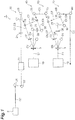
- FIG. 1 is a schematic diagram illustrating an entire configuration of a laser device according to the embodiment.
- the laser device 1 includes a two-stage amplification mechanism.
- the laser device 1 includes a light source 2, a laser medium 3, a first optical system 10, a second optical system 20, and a third optical system 40 as a first-stage amplification mechanism.
- the light source 2 outputs seed light (seed light C0).
- the seed light is, for example, laser light having a wavelength of about 1030 nm.
- the laser medium 3 amplifies the seed light.
- the laser medium 3 is, for example, a laser gain medium including Yb as an active element (for example, Yb: YAG).
- the first optical system 10 outputs excitation light E1 for exciting the laser medium 3 and inputs the excitation light E1 to an excitation region R to be described below by causing the excitation light E1 to be incident on the laser medium 3.
- a wavelength of the excitation light E1 is different from the wavelength of the seed light.
- the excitation light E1 is, for example, laser light having a wavelength of about 940 nm.
- the second optical system 20 guides the seed light from the light source 2 and inputs the seed light to the excitation region R of the laser medium 3.
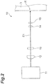
- FIG. 2 is a schematic diagram illustrating the first optical system illustrated in FIG. 1 .
- the first optical system 10 has an excitation light source 11 and lenses 12, 13, 14 and 15.
- the excitation light source 11 outputs the excitation light E1.
- the excitation light source 11 is, for example, a semiconductor laser device.
- the excitation light source 11 can be constituted by a semiconductor laser array,
- the lenses 12 to 15 condense the excitation light E1 output from the excitation light source 11 on the excitation region R.
- the lenses 12 to 15 are, for example, cylindrical lenses.
- the lenses 12 to 15 are arranged in order from the excitation light source 11 to the laser medium 3.
- the lens 12 collimates the excitation light E1 output from the excitation light source 11 in a fast axis direction.
- the lens 13 collimates the excitation light E1 from the lens 12 in a slow axis direction.
- the lens 14 condenses the excitation light E1 from the lens 13 in the fast axis direction.
- the lens 15 condenses the excitation light E1 from the lens 14 in the slow axis direction. Accordingly, the excitation light E1 is condensed in both the fast axis direction and the slow axis direction and input to the excitation region R of the laser medium 3.
- FIG. 3 is a schematic diagram illustrating enlarged main parts of FIG. 1 .
- the laser medium 3 is formed, for example, in a flat plate shape.
- the laser medium 3 has a first surface 3a and a second surface 3b opposite to the first surface 3a.
- the first surface 3a and the second surface 3b are, for example, parallel to each other.
- the first optical system 10 is disposed on the first surface 3a side, and inputs the excitation light E 1 to the excitation region R by causing the excitation light E 1 to be incident on the laser medium 3 from the first surface 3a side.
- Main configurations of the second optical system 20 and the third optical system 40 are disposed on the second surface 3b side.
- the second optical system 20 and the third optical system 40 input the seed light to the excitation region R by causing the seed light to be incident on the laser medium 3 from the second surface 3b side.
- a coat (a first mirror or a third mirror) 4 is formed on the first surface 3a, and a coat 5 is formed on the second surface 3b.
- the coats 4 and 5 are, for example, dielectric multilayer films.
- the coat 4 includes a non-reflective coat for the wavelength of the excitation light E1 and a reflective coat for the wavelength of the seed light. That is, the coat 4 transmits the excitation light E1 and reflects the seed light.
- the coat 5 includes a reflective coat for the wavelength of the excitation light E1 and a non-reflective coat for the wavelength of the seed light. That is, the coat 5 reflects the excitation light E1 and transmits the seed light.
- the second optical system 20 includes mirrors 21 and 22, an optical isolator 23, a phase shift element 24, a mirror 25, a first beam splitter 26, a first phase shift element 27, and a mirror (a second mirror) 28.
- the third optical system 40 includes a second beam splitter 29, a mirror (a third mirror) 30, a second phase shift element 31, a mirror (a third mirror) 32, a mirror 33, and an optical isolator 34.
- the first beam splitter 26 and the second beam splitter 29 are polarization beam splitters
- the first phase shift element 27 and the second phase shift element 31 are, for example, wavelength plates (here, ⁇ /4 wavelength plates).
- the mirrors 21 and 22 guide the seed light C0 output from the light source 2 by reflecting the seed light C0 and input the seed light C0 to the optical isolator 23.
- the optical isolator 23 prevents return light.
- the phase shift element 24 receives the seed light C0 output from the optical isolator 23.
- the phase shift element 24 applies a phase difference to polarization components of the seed light C0, and outputs resultant light as seed light C1 of the first polarization (for example, P polarization).
- the mirror 25 reflects the seed light C1 of the first polarization output from the phase shift element 24 and inputs the seed light C1 to the first beam splitter 26.
- the first beam splitter 26 has a function of passing the seed light of the first polarization toward the laser medium 3 and reflecting the seed light of the first polarization so that seed light of second polarization (for example, S polarization) different from the first polarization by 90 ° is directed to the second beam splitter 29. Therefore, the first beam splitter 26 passes, toward the laser medium 3, the seed light C1 that has been converted into the first polarization by the phase shift element 24 and guided by the mirror 25.
- second polarization for example, S polarization
- the first phase shift element 27 is disposed between the first beam splitter 26 and the laser medium 3.
- the first phase shift element 27 has a function of applying a phase difference of a 1/4 wavelength to a polarization component of light. Therefore, here, the first phase shift element 27 receives the seed light C1 from the first beam splitter 26, applies a phase difference of a 1/4 wavelength to a polarization component thereof, and outputs the resultant light as the seed light C2.
- the seed light C2 output from the first phase shift element 27 is input to the laser medium 3 (the excitation region R) and subjected to amplification in the laser medium 3.
- the seed light C2 is obliquely incident at an incidence angle (for example, about 30°) larger than 0° with respect to the first surface 3a of the laser medium 3.
- the coat 4 reflects the seed light C2 incident on the laser medium 3 through the first phase shift element 27 and traveling in the laser medium 3 so that the seed light C2 travels in the laser medium 3 again and is emitted from the laser medium 3.
- the coat 4 obliquely emits the seed light C2 at an angle corresponding to the incidence angle to the laser medium 3.
- the mirror 28 reflects the seed light C2 reflected by the coat 4, and causes the seed light C2 to return to the coat 4.
- a reflective surface of the mirror 28 is orthogonal to the seed light C2 (the mirror 28 is a 0° mirror). Therefore, the seed light C2 reflected by the mirror 28 returns to the laser medium 3 through an optical path from the coat 4 to the mirror 28 in a reverse direction.
- the seed light C2 returned to the laser medium 3 is reflected again by the coat 4 and directed to the first phase shift element 27 and the first beam splitter 26. That is, the mirror 28 reflects the seed light C2 reflected by the coat 4 so that the seed light C2 returns to the coat 4 through the laser medium 3, thereby reflecting the seed light C2 so that the seed light C2 is directed to the first beam splitter 26 through the first phase shift element 27. Accordingly, the seed light C2 passes through the laser medium 3 (the excitation region R) four times and is amplified.
- the first phase shift element 27 is interposed between the laser medium 3 and the first beam splitter 26. Therefore, the first phase shift element 27 receives the amplified seed light C2 reflected by the coat 4 and the mirror 28, applies a phase difference of a 1/4 wavelength to the polarization component thereof, and outputs the resultant light as seed light C3.
- a polarization direction of the seed light C3 output from the first phase shift element 27 is rotated by 90° due to shift by a 1/2 wavelength of a phase of the polarization component, as compared with the seed light C1, such that the seed light C3 gains the second polarization.
- the seed light C3 output from the first phase shift element 27 is input to the first beam splitter 26.
- the first beam splitter 26 has a function of reflecting the seed light of the second polarization so that the seed light is directed to the second beam splitter 29. Therefore, the first beam splitter 26 reflects the seed light C3 of the second polarization toward the second beam splitter 29.
- the second beam splitter 29 has a function of reflecting the seed light of the second polarization toward the laser medium 3 and transmitting the seed light of the first polarization. Therefore, the second beam splitter 29 reflects the seed light C3 of the second polarization from the first beam splitter 26 so that the seed light C3 is directed to the laser medium 3.
- the second beam splitter 29 reflects the seed light C3 toward the mirror 30.
- the mirror 30 reflects the seed light C3 from the second beam splitter 29 toward the mirror 32.
- the mirror 32 reflects the seed light C3 from the mirror 30 toward the laser medium 3.
- the second phase shift element 31 has a function of applying a phase difference of a 1/4 wavelength to a polarization component of light.
- the second phase shift element 31 is disposed between the mirror 30 and the mirror 32, that is, between the second beam splitter 29 and the laser medium 3. Therefore, the second phase shift element 31 receives the seed light C3 from the second beam splitter 29 through the mirror 30, applies a phase difference of a 1/4 wavelength to a polarization component thereof, and outputs the resultant light as seed light C4.
- the seed light C4 output from the second phase shift element 31 is reflected by the mirror 32 and input to the laser medium 3.
- the seed light C4 is incident at an incidence angle of 0° with respect to the first surface 3a of the laser medium 3.
- the coat 4 reflects the seed light C4 incident on the laser medium 3 toward the mirror 32.
- a reflective surface of the coat 4 is orthogonal to the seed light C4 (the coat 4 is a 0° mirror with respect to the seed light C4). Therefore, the seed light C4 reflected by the coat 4 is directed to the mirrors 32 and 30, the second phase shift element 31, and the second beam splitter 29 in a reverse direction of an optical path directed from the mirror 32 to the coat 4. That is, the coat 4 and the mirrors 32 and 30 reflect the seed light C4 input to the laser medium 3 through the second phase shift element 31 so that the seed light C4 is directed to the second beam splitter 29 through the second phase shift element 31. Accordingly, the seed light C4 passes through the laser medium 3 (the excitation region R) twice and is amplified.
- the second phase shift element 31 is interposed between the mirror 32 and the mirror 30. Therefore, the second phase shift element 31 receives the amplified seed light C4 reflected by the coat 4, applies a phase difference of a 1/4 wavelength to a polarization component thereof, and outputs the resultant light as seed light C5.
- a polarization direction of the seed light C5 output from the second phase shift element 31 is rotated by 90 ° due to shift by a 1/2 wavelength of a phase of the polarization component, as compared with the seed light C3, and the seed light C5 gains first polarization.
- the seed light C5 output from the second phase shift element 31 is input to the second beam splitter 29 through the mirror 30.
- the second beam splitter 29 has a function of passing the seed light of the first polarization. Therefore, the second beam splitter 29 passes the seed light C5 of the first polarization from the mirror 30. The seed light C5 passing through the second beam splitter 29 is reflected by the mirror 33 and then subjected to a second-stage amplification mechanism. As described above, in the laser device 1, six paths passing through the laser medium 3 are formed in the first-stage amplification mechanism, and the seed light is amplified six times.
- the optical isolator 34 is disposed between the first beam splitter 26 and the second beam splitter 29.
- the optical isolator 34 passes light only in a direction from the first beam splitter 26 to the second beam splitter 29, and prevents light from being passed in a reverse direction.
- the laser device 1 further includes, as a second-stage amplification mechanism, a configuration that is substantially the same as the first-stage amplification mechanism. That is, the laser device 1 includes a mirror 51, a laser medium 3, a first optical system 10, a second optical system 50, and a third optical system 70, as the second-stage amplification mechanism.
- the seed light C5 from the first-stage amplification mechanism is reflected by the mirror 51 and introduced into the second optical system 50.
- the second optical system 50 includes a first beam splitter 52, a first phase shift element 53, and a mirror (a second mirror) 54.
- the third optical system 70 includes a second beam splitter 55, a mirror (a third mirror) 56, a second phase shift element 58, a mirror (a third mirror) 57, a mirror 59, and an optical isolator (not illustrated).
- the first beam splitter 52 and the second beam splitter 55 are polarization beam splitters
- the first phase shift element 53 and the second phase shift element 58 are, for example, wavelength plates (here, ⁇ /4 wavelength plates).
- the first beam splitter 52 has a function of passing the seed light of the first polarization so that the seed light is directed to the laser medium 3, and reflecting the seed light of the second polarization different by 90° from the first polarization so that the seed light is directed to the second beam splitter. Therefore, the first beam splitter 52 passes the seed light C5 of the first polarization guided by the mirror 51 toward the laser medium 3.
- the first phase shift element 53 is disposed between the first beam splitter 52 and the laser medium 3.
- the first phase shift element 53 has a function of applying a phase difference of a 1/4 wavelength to a polarization component of light. Therefore, here, the first phase shift element 53 receives the seed light C5 from the first beam splitter 52, applies a phase difference of a 1/4 wavelength to a polarization component thereof, and outputs the resultant light as seed light C6.
- the seed light C6 output from the first phase shift element 53 is input to the laser medium 3 (the excitation region R) and subjected to amplification in the laser medium 3.
- the seed light C6 is obliquely incident at an incidence angle (for example, about 30°) larger than 0° with respect to the first surface 3 a of the laser medium 3.
- the coat 4 reflects the seed light C6 incident on the laser medium 3 through the first phase shift element 53 and traveling in the laser medium 3 so that the seed light C6 travels in the laser medium 3 again and is emitted from the laser medium 3.
- the coat 4 obliquely emits the seed light C6 at an angle according to an angle of incidence on the laser medium 3.
- the mirror 54 reflects the seed light C6 reflected by the coat 4 and causes the seed light C6 to return to the coat 4.
- a reflection surface of the mirror 54 is orthogonal to the seed light C6 (the mirror 54 is a 0° mirror). Therefore, the seed light C6 reflected by the mirror 54 returns to the laser medium 3 in a reverse direction of an optical path directed from the coat 4 to the mirror 54.
- the seed light C2 returned to the laser medium 3 is reflected again by the coat 4 and directed to the first phase shift element 53 and the first beam splitter 52. That is, the mirror 54 reflects the seed light C2 reflected by the coat 4 so that the seed light C2 returns to the coat 4 through the laser medium 3 and is directed to the first beam splitter 52 through the first phase shift element 53. Accordingly, the seed light C6 passes through the laser medium 3 (the excitation region R) four times and is amplified.
- the first phase shift element 53 is interposed between the laser medium 3 and the first beam splitter 52. Therefore, the first phase shift element 53 receives the amplified seed light C6 reflected by the coat 4 and the mirror 54, applies a phase difference of a 1/4 wavelength to a polarization component thereof, and outputs the resultant light as seed light C7.
- a polarization direction of the seed light C7 output from the first phase shift element 53 is rotated by 90° due to shift by a 1/2 wavelength of a phase of the polarization component, as compared with the seed light C5, and the seed light C7 gains the second polarization.
- the seed light C7 output from the first phase shift element 53 is input to the first beam splitter 52.
- the first beam splitter 52 has a function of reflecting the seed light of the second polarization so that the seed light is directed to the second beam splitter 55. Therefore, the first beam splitter 52 reflects the seed light C7 of the second polarization toward the second beam splitter 55.
- the second beam splitter 55 has a function of reflecting the seed light of the second polarization toward the laser medium 3 and passing the seed light of the first polarization. Therefore, the second beam splitter 55 reflects the seed light C7 of the second polarization from the first beam splitter 52 so that the seed light C7 is directed to the laser medium 3.
- the second beam splitter 55 reflects the seed light C7 toward the mirror 56.
- the mirror 56 reflects the seed light C7 from the second beam splitter 55 toward the mirror 57.
- the mirror 57 reflects the seed light C7 from the mirror 56 toward the laser medium 3.
- the second phase shift element 58 has a function of applying a phase difference of a 1/4 wavelength to a polarization component of light.
- the second phase shift element 58 is disposed between the mirror 57 and the laser medium 3, that is, between the second beam splitter 55 and the laser medium 3. Therefore, the second phase shift element 58 receives the seed light C7 from the second beam splitter 55 through the mirrors 56 and 57, applies a phase difference of a 1/4 wavelength to a polarization component thereof, and outputs the resultant light as seed light C8.
- the seed light C8 output from the second phase shift element 58 is input to the laser medium 3.
- the seed light C8 is incident at an incidence angle of 0° with respect to the first surface 3a of the laser medium 3.
- the coat 4 reflects the seed light C8 incident on the laser medium 3 toward the mirror 57.
- the reflective surface of the coat 4 is orthogonal to the seed light C8 (the coat 4 is a 0° mirror with respect to the seed light C8). Therefore, the seed light C8 reflected by the coat 4 is directed to the second phase shift element 58, the mirrors 57 and 56, and the second beam splitter 55 in a reverse direction of an optical path from the mirror 57 to the coat 4. That is, the coat 4 and the mirrors 57 and 56 reflect the seed light C8 input to the laser medium 3 through the second phase shift element 58 so that the seed light C8 is directed to the second beam splitter 55 through the second phase shift element 58. Accordingly, the seed light C8 passes through the laser medium 3 (the excitation region R) twice and is amplified.
- the second phase shift element 58 receives the amplified seed light C8 reflected by the coat 4, applies a phase difference of a 1/4 wavelength to a polarization component thereof, and outputs the resultant as seed light C9.
- a polarization direction of the seed light C9 output from the second phase shift element 58 is rotated by 90° due to shift by a 1/2 wavelength of a phase of the polarization component, as compared with the seed light C7, and the seed light C9 gains first polarization.
- the seed light C9 output from the second phase shift element 58 is input to the second beam splitter 55 through the mirrors 56 and 57.
- the second beam splitter 55 has a function of passing the seed light of the first polarization. Therefore, the second beam splitter 55 passes the seed light C9 from the mirror 57. The seed light C9 passing through the second beam splitter 55 is reflected by the mirrors 59 and 60, and then, taken out as output light. As described above, in the laser device 1, six paths passing through the laser medium 3 are also formed in the second-stage amplification mechanism, and the seed light is amplified six times.
- the laser device 1 may include a Faraday rotator that is a polarization rotation element, instead of the phase shift elements such as the first phase shift elements 27 and 53 and the second phase shift elements 31 and 58 described above.
- FIGS. 4A and 4B are diagrams illustrating an example of the Faraday rotator.
- the Faraday rotator is a polarization rotation element using a Faraday effect, which is a phenomenon in which a polarization of light traveling in a magnetic field rotates.
- the Faraday rotator FR when the Faraday rotator FR receives light L1 of first polarization Da traveling in a first direction, the Faraday rotator FR rotates a polarization direction thereof by 45° and outputs light L2 of second polarization Db.
- the Faraday rotator FR when the Faraday rotator FR receives the light L2 of second polarization Db traveling in a second direction opposite to the first direction, the Faraday rotator FR rotates a polarization direction thereof by 45° and outputs light L3 of third polarization Dc (polarization rotated by 90° from the first polarization Da).
- the Faraday rotator is disposed between the first beam splitters 26 and 52 and the laser medium 3, receives the seed lights C1 and C5 from the first beam splitters 26 and 52, rotates polarization directions thereof by 45°, and outputs the resultant lights as seed lights C2 and C6. Further, in this case, the Faraday rotator receives the amplified seed lights C2 and C6 reflected by the coat 4, rotates the polarization directions thereof by 45°, and outputs the resultant lights as the seed lights C3 and C7.
- the Faraday rotator is disposed between the second beam splitters 29 and 55 and the laser medium 3, receives the seed lights C3 and C7 from the second beam splitters 29 and 55, rotates polarization directions thereof by 45°, and outputs the resultant lights as seed lights C4 and C8. Further, in this case, the Faraday rotator receives the amplified seed lights C4 and C8 reflected by the coat 4, rotates polarization direction thereof by 45°, and outputs the resultant lights as the seed light C5 and C9.
- FIGS. 5A and 5B are diagrams illustrating a Faraday isolator.
- a Faraday isolator FI includes a Faraday rotator FR and polarization elements Pa and Pb.
- the polarization element Pa, the Faraday rotator FR, and the polarization element Pb are arranged in order in the first direction.
- the polarization element Pa passes only the light L1 of the first polarization Da.
- the polarization element Pb passes only the light L2 of the second polarization Db different by 45° from the first polarization 45.
- the seed light C1 that is an amplification target is input to the first beam splitter 26 in the first polarization.
- the seed light C1 of the first polarization passes through the first beam splitter 26 and is directed to the laser medium 3.
- the seed light C1 of the first polarization directed from the first beam splitter 26 to the laser medium 3 passes through the first phase shift element 27, such that a phase difference of a 1/4 wavelength is applied to a polarization component thereof.
- the seed light C2 passing through the first phase shift element 27 is incident on the laser medium 3 at an incidence angle larger than 0°.
- the seed light C2 incident on the laser medium 3 is input to the excitation region R, amplified, reflected by the coat 4, amplified again, and then emitted from the laser medium 3.
- the seed light C2 emitted from the laser medium 3 is reflected by the mirror 28 and incident on the laser medium 3 again.
- the seed light C2 reflected by the mirror 28 and incident on the laser medium 3 is reflected again by the coat 4 and directed to the first beam splitter 26 through the first phase shift element 27.
- the seed light C3 passes through the first phase shift element 27 again. Accordingly, a phase difference of a 1/4 wavelength is further applied to the polarization component thereof, and the seed light C3 gains the second polarization (for example, S polarization). Therefore, the seed light C3 is reflected and split by the first beam splitter 26.
- the seed light C3 split by the first beam splitter 26, for example, may be guided to the laser medium 3 by another optical system (here, the third optical system 40) again and subjected to further amplification.
- the laser device 1 both of separation of an amplification path according to a polarization direction by the first beam splitter 26 and the first phase shift element 27 and doubling of an amplification path by the coat 4 and the mirror 28 are achieved. As a result, it is possible to achieve high output by realizing a large number of amplifications with a simple configuration.
- the laser device 1 further includes the third optical system 40 for causing the seed light C3 of the second polarization reflected by the first beam splitter 26 to be incident on the laser medium 3 and input to the excitation region R.
- the third optical system 40 includes the second beam splitter 29 that reflects the seed light C3 of the second polarization from the first beam splitter 26 so that the seed light C3 is directed to the laser medium 3 and passes the seed light C5 of the first polarization from the laser medium 3, the second phase shift element 31 that is disposed between the second beam splitter 29 and the laser medium 3 and applies a phase difference of a 1/4 wavelength to the polarization component of the seed light C3, and the coat 4 that reflects the seed light C4 incident on the laser medium 3 through the second phase shift element 31 so that the seed light C4 is directed to the second beam splitter 29 through the second phase shift element 31.
- the seed light C3 split by the first beam splitter 26 is input to the second beam splitter 29.
- the seed light C3 of the second polarization input to the second beam splitter 29 is reflected by the second beam splitter 29 so that the seed light C3 is directed to the laser medium 3.
- the seed light C3 of the second polarization directed to the laser medium 3 from the second beam splitter 29 passes through the second phase shift element 31, such that a phase difference of a 1/4 wavelength is applied to a polarization component thereof.
- the seed light C4 passing through the second phase shift element 31 is input to the excitation region R of the laser medium 3, is amplified, is reflected by the coat 4, is amplified again, passes through the second phase shift element 31 again, and then, is input to the second beam splitter 29.
- the seed light c5 passes through the second phase shift element 31 again, such that a phase difference of a 1/4 wavelength is further applied to the polarization component of the seed light c5, and the seed light c5 is caused to be first polarization. Therefore, the seed light C5 passes through the second beam splitter 29. As a result, the seed light C5 passing through the second beam splitter 29 is amplified at least six times and output. Thus, in the laser device 1, it is possible to achieve high output by realizing a larger number of amplifications with a simple configuration.
- the laser medium 3 includes the first surface 3a and the second surface 3b opposite to the first surface 3a.
- the first optical system 10 causes the excitation light E1 to be incident on the laser medium 3 from the first surface 3 a side
- the second optical system 20 and the third optical system 40 cause the seed light to be incident on the laser medium 3 from the second surface 3b side. Therefore, the optical path of the excitation light E1 and the optical path of the seed light are distributed to both sides of the laser medium 3. Therefore, it is possible to design the optical system without considering interference of each optical path.
- the coat 4 that transmits the excitation light E1 and reflects the seed light is formed on the first surface 3a.
- the mirror reflecting the seed lights C2 and C4 includes a mirror constituted by the coat 4. Therefore, it is possible to achieve high output with a simpler configuration.
- the laser device 1 further includes the optical isolator 34 that is disposed between the first beam splitter 26 and the second beam splitter 29 and passes light in a direction directed from the first beam splitter 26 to the second beam splitter 29. Therefore, progress of the light in the direction directed from the second beam splitter 29 to the first beam splitter 26 is suppressed. As a result, unintended resonator configuration and stimulated radiation are avoided.
- seed light reciprocates in paths from the first beam splitter 26 to the laser medium 3 and from the second beam splitter 29 to the laser medium 3. Therefore, as in this case, it is effective to interpose the optical isolator 34 between the first beam splitter 26 and the second beam splitter 29 in which the reciprocation of the seed light is not required.
- the laser medium 3 may include Yb as an active element.
- the excitation light E1 and the seed light it is necessary for the excitation light E1 and the seed light to be input to a narrower excitation region R for high intensity excitation, for example, as compared with a case in which a Nd-based laser medium is used. Therefore, importance of high-precision and easy alignment of the optical system is relatively higher. Therefore, it is more effective to realize a simple configuration using the laser device 1.
- a Faraday rotator serving as a polarization rotation element may be used instead of the first phase shift element 27 and the second phase shift element 31. In this case, a variation in the polarization direction due to heat generated in the laser medium 3 can be compensated for.
- the laser device according to the present disclosure is not limited to the laser device 1 described above, and various modifications are possible.
- the Yb-based laser gain medium is illustrated as the laser medium 3.
- the laser medium 3 may be, for example, a laser medium including Nd as an active element (for example, Nd: YAG).
- the coat 4 provided on the first surface 3a of the laser medium 3 is used as the mirror that reflects the seed lights C2 and C4 has been shown in the above embodiment.
- a configuration in which the seed lights C2 and C4 are transmitted through the laser medium 3 may be adopted, and a separate mirror that reflects the seed lights C2 and C4 toward the first surface 3a may be provided at a position spaced from the first surface 3a.
- the laser device 1 may include the two-stage amplification mechanism, the laser device 1 may include a one-stage amplification mechanism or the laser device 1 may include a three-or-more-stage amplification mechanism. Furthermore, the laser device 1 may not include the light source 2.
- a laser device including:
- the laser medium includes a first surface, and a second surface opposite to the first surface
- the first optical system causes the excitation light to be incident on the laser medium from the first surface side
- the second optical system and the third optical system cause the seed light to be incident on the laser medium from the second surface side.
- the laser device wherein a coat that transmits the excitation light and reflects the seed light is formed on the first surface, and the first mirror and the third mirror include a mirror constituted by the coat.
- the laser device including: an optical isolator that is disposed between the first beam splitter and the second beam splitter and passes light in a direction directed from the first beam splitter to the second beam splitter.
- optical isolator includes a Faraday isolator.
- the laser device according to any one of claims 1 to 8, wherein the laser medium includes Yb as an active element.
Landscapes
- Physics & Mathematics (AREA)
- Electromagnetism (AREA)
- Engineering & Computer Science (AREA)
- Plasma & Fusion (AREA)
- Optics & Photonics (AREA)
- Lasers (AREA)
Abstract
Description
- The present disclosure relates to a laser device.
- A laser device is described in Japanese Unexamined Patent Publication No.
2005-327857 - Incidentally, since laser devices that output much pulse energy are large and expensive and have a low repetition rate, industrial development is difficult. In recent years, various solid-state laser devices that are small and have a high repetition rate have been developed with high output of the semiconductor lasers. Among these laser devices, Yb-based lasers are expected to have a high output with a smaller number of semiconductor lasers than in Nd-based lasers. However, since Yb-based lasers are three-level lasers, special measures different from those for Nd-based lasers may be required, such as achievement of low doped ion concentration, high intensity excitation, and low temperature.
- On the other hand, according to a multipath scheme, as in a laser device described in Japanese Unexamined Patent Publication No.
2005-327857 - An object of the present disclosure is to provide a laser device capable of achieving high output with a simple configuration.
- A laser device includes a laser medium for amplifying seed light; a first optical system for outputting excitation light for exciting the laser medium and causing the excitation light to be incident on the laser medium and input to an excitation region of the laser medium; and a second optical system for causing the seed light of a first polarization to be incident on the laser medium at an incidence angle larger than 0° with respect to the laser medium and input to the excitation region, wherein the second optical system includes a first beam splitter that passes the seed light of the first polarization so that the seed light is directed to the laser medium and reflects the seed light of second polarization different from the first polarization from the laser medium; a first phase shift element that is disposed between the first beam splitter and the laser medium and applies a phase difference of a 1/4 wavelength to a polarization component of the seed light; a first mirror that reflects the seed light incident on the laser medium through the first phase shift element so that the seed light is emitted from the laser medium; and a second mirror that directs the seed light to the first beam splitter through the first phase shift element by causing the seed light to reflect again by the first mirror by reflecting the seed light so that the seed light returns to the first mirror through the laser medium.
- In this laser device, the seed light that is an amplification target is input to the first beam splitter in the first polarization (for example, P polarization). The seed light of the first polarization passes through the first beam splitter and is directed to the laser medium. The seed light of the first polarization directed from the first beam splitter to the laser medium passes through the first phase shift element, such that a phase difference of a 1/4 wavelength is applied to a polarization component thereof. The seed light passing through the first phase shift element is incident on the laser medium at an incidence angle larger than 0°. The seed light incident on the laser medium is input to the excitation region, amplified, reflected by the first mirror, amplified again, and then emitted from the laser medium. The seed light emitted from the laser medium is reflected by the second mirror and incident on the laser medium again. The seed light reflected by the second mirror and incident on the laser medium is reflected again by the first mirror and directed to the first beam splitter through the first phase shift element.
- In this time, the seed light passes through the first phase shift element again, and then a phase difference of a 1/4 wavelength is further applied to the polarization component thereof, and the seed light is caused to be the second polarization (for example, S polarization). Therefore, the seed light is reflected and split by the first beam splitter and split. The seed light split by the first beam splitter, for example, may be guided to the laser medium by another optical system again and subjected to further amplification. Thus, in the laser device, both of separation of an amplification path according to a polarization direction by the first beam splitter and the first phase shift element and doubling of an amplification path by the first mirror and the second mirror are achieved. As a result, it is possible to achieve high output by realizing a large number of amplifications with a simple configuration. It should be noted that the first beam splitter is a polarization beam splitter.
- The laser device may include a third optical system for causing the seed light of the second polarization reflected by the first beam splitter to be incident on the laser medium and input to the excitation region, wherein the third optical system may include a second beam splitter that reflects the seed light of the second polarization from the first beam splitter so that the seed light is directed to the laser medium, and passes the seed light of the first polarization from the laser medium; a second phase shift element that is disposed between the second beam splitter and the laser medium and applies a phase difference of a 1/4 wavelength to a polarization component of the seed light; and a third mirror that reflects the seed light incident on the laser medium through the second phase shift element so that the seed light is directed to the second beam splitter through the second phase shift element.
- In this case, the seed light split by the first beam splitter is input to the second beam splitter. The seed light of the second polarization input to the second beam splitter is reflected by the second beam splitter so that the seed light is directed to the laser medium. The seed light of the second polarization directed to the laser medium from the second beam splitter passes through the second phase shift element, such that a phase difference of a 1/4 wavelength is applied to a polarization component thereof. The seed light passing through the second phase shift element is input to the excitation region of the laser medium, is amplified, is reflected by the third mirror, is amplified again, passes through the second phase shift element again, and then, is input to the second beam splitter.
- In this case, the seed light passes through the second phase shift element again, such that a phase difference of a 1/4 wavelength is further applied to the polarization component thereof, and the seed light gains the first polarization. Therefore, the seed light passes through the second beam splitter. As a result, the seed light passing through the second beam splitter is amplified at least six times and output. Thus, in the laser device, it is possible to achieve high output by realizing a larger number of amplifications with a simple configuration. It should be noted that the second beam splitter is a polarization beam splitter.
- The laser device may include an optical isolator that is disposed between the first beam splitter and the second beam splitter and passes light in a direction directed from the first beam splitter to the second beam splitter. In this case, progress of the light in the direction directed from the second beam splitter to the first beam splitter is suppressed. As a result, unintended resonator configuration and stimulated radiation are avoided. It should be noted that, in the laser device, seed light reciprocates in paths from the first beam splitter to the laser medium and from the second beam splitter to the laser medium. Therefore, as in this case, it is effective to interpose the optical isolator between the first beam splitter and the second beam splitter in which the reciprocation of the seed light is not required. It should be noted that the optical isolator may include a Faraday isolator.
- In the laser device, the laser medium may include a first surface, and a second surface opposite to the first surface, the first optical system may cause the excitation light to be incident on the laser medium from the first surface side, and the second optical system may cause the seed light to be incident on the laser medium from the second surface side. In this case, an optical path of the excitation light and an optical path of the seed light are distributed to both sides of the laser medium. Therefore, it is possible to design an optical system without considering interference between the respective optical paths.
- In the laser device, a coat that transmits the excitation light and reflects the seed light may be formed on the first surface, and the first mirror may include a mirror constituted by the coat. In this case, it is possible to achieve higher output with a simpler configuration.
- In the laser device, the laser medium may include Yb as an active element. Thus, when the Yb-based laser medium is used, it is necessary for excitation light and seed light to be input to a narrower excitation region for high intensity excitation, for example, as compared with a case in which a Nd-based laser medium is used. Therefore, an importance of high-precision and easy alignment of the optical system is relatively higher. Therefore, it is more effective to realize a simple configuration using this laser device.
- A laser device includes: a laser medium for amplifying seed light; a first optical system for outputting excitation light for exciting the laser medium and causing the excitation light to be incident on the laser medium and input to an excitation region of the laser medium; and a second optical system for causing the seed light of first polarization to be incident on the laser medium at an incidence angle larger than 0° with respect to the laser medium and input to the excitation region, wherein the second optical system includes a first beam splitter that passes the seed light of the first polarization so that the seed light is directed to the laser medium and reflects the seed light of second polarization different by 90° from the first polarization from the laser medium; a Faraday rotator that is disposed between the first beam splitter and the laser medium and rotates a polarization direction of the seed light by 45°; a first mirror that reflects the seed light incident on the laser medium through the Faraday rotator so that the seed light is emitted from the laser medium; and a second mirror that directs the seed light to the first beam splitter through the Faraday rotator by causing the seed light to reflect again by the first mirror by reflecting the seed light so that the seed light returns to the first mirror through the laser medium.
- In this laser device, it is possible to achieve high output by realizing a large number of amplifications with a simple configuration, as in the laser device described above. In particular, in this laser device, a Faraday rotator is used as the polarization rotation element. Therefore, it is possible to compensate for a variation in the polarization direction due to heat generated in the laser medium.
- According to the present disclosure, it is possible to provide a laser device capable of achieving high output with a simple configuration.
-
-
FIG. 1 is a schematic diagram illustrating an entire configuration of a laser device according to an embodiment of the present invention. -
FIG. 2 is a schematic diagram illustrating a first optical system illustrated inFIG. 1 . -
FIG. 3 is a schematic diagram illustrating enlarged main parts ofFIG. 1 . -
FIG. 4A is a diagram illustrating an example of a Faraday rotator. -
FIG. 4B is a diagram illustrating an example of a Faraday rotator. -
FIG. 5A is a diagram illustrating an example of a Faraday isolator. -
FIG. 5B is a diagram illustrating an example of a Faraday isolator. - Hereinafter, an embodiment will be described in detail with reference to the drawings. In the drawings, the same elements or corresponding elements may be denoted by the same reference numerals, and redundant description may be omitted.
-
FIG. 1 is a schematic diagram illustrating an entire configuration of a laser device according to the embodiment. As illustrated inFIG. 1 , the laser device 1 includes a two-stage amplification mechanism. The laser device 1 includes alight source 2, alaser medium 3, a firstoptical system 10, a secondoptical system 20, and a thirdoptical system 40 as a first-stage amplification mechanism. Thelight source 2 outputs seed light (seed light C0). The seed light is, for example, laser light having a wavelength of about 1030 nm. Thelaser medium 3 amplifies the seed light. Thelaser medium 3 is, for example, a laser gain medium including Yb as an active element (for example, Yb: YAG). - The first
optical system 10 outputs excitation light E1 for exciting thelaser medium 3 and inputs the excitation light E1 to an excitation region R to be described below by causing the excitation light E1 to be incident on thelaser medium 3. A wavelength of the excitation light E1 is different from the wavelength of the seed light. The excitation light E1 is, for example, laser light having a wavelength of about 940 nm. The secondoptical system 20 guides the seed light from thelight source 2 and inputs the seed light to the excitation region R of thelaser medium 3. -
FIG. 2 is a schematic diagram illustrating the first optical system illustrated inFIG. 1 . As illustrated inFIG. 2 , the firstoptical system 10 has anexcitation light source 11 andlenses excitation light source 11 outputs the excitation light E1. Theexcitation light source 11 is, for example, a semiconductor laser device. As an example, theexcitation light source 11 can be constituted by a semiconductor laser array, Thelenses 12 to 15 condense the excitation light E1 output from theexcitation light source 11 on the excitation region R. Thelenses 12 to 15 are, for example, cylindrical lenses. Thelenses 12 to 15 are arranged in order from theexcitation light source 11 to thelaser medium 3. - The
lens 12 collimates the excitation light E1 output from theexcitation light source 11 in a fast axis direction. Thelens 13 collimates the excitation light E1 from thelens 12 in a slow axis direction. Thelens 14 condenses the excitation light E1 from thelens 13 in the fast axis direction. Thelens 15 condenses the excitation light E1 from thelens 14 in the slow axis direction. Accordingly, the excitation light E1 is condensed in both the fast axis direction and the slow axis direction and input to the excitation region R of thelaser medium 3. -
FIG. 3 is a schematic diagram illustrating enlarged main parts ofFIG. 1 . As illustrated inFIGS. 1 to 3 , thelaser medium 3 is formed, for example, in a flat plate shape. Thelaser medium 3 has afirst surface 3a and asecond surface 3b opposite to thefirst surface 3a. Thefirst surface 3a and thesecond surface 3b are, for example, parallel to each other. The firstoptical system 10 is disposed on thefirst surface 3a side, and inputs the excitation light E 1 to the excitation region R by causing the excitation light E 1 to be incident on thelaser medium 3 from thefirst surface 3a side. Main configurations of the secondoptical system 20 and the thirdoptical system 40 are disposed on thesecond surface 3b side. The secondoptical system 20 and the thirdoptical system 40 input the seed light to the excitation region R by causing the seed light to be incident on thelaser medium 3 from thesecond surface 3b side. - A coat (a first mirror or a third mirror) 4 is formed on the
first surface 3a, and acoat 5 is formed on thesecond surface 3b. Thecoats 4 and 5 are, for example, dielectric multilayer films. The coat 4 includes a non-reflective coat for the wavelength of the excitation light E1 and a reflective coat for the wavelength of the seed light. That is, the coat 4 transmits the excitation light E1 and reflects the seed light. Thecoat 5 includes a reflective coat for the wavelength of the excitation light E1 and a non-reflective coat for the wavelength of the seed light. That is, thecoat 5 reflects the excitation light E1 and transmits the seed light. - The second
optical system 20 includesmirrors optical isolator 23, aphase shift element 24, amirror 25, afirst beam splitter 26, a firstphase shift element 27, and a mirror (a second mirror) 28. The thirdoptical system 40 includes asecond beam splitter 29, a mirror (a third mirror) 30, a secondphase shift element 31, a mirror (a third mirror) 32, amirror 33, and anoptical isolator 34. It should be noted that thefirst beam splitter 26 and thesecond beam splitter 29 are polarization beam splitters, and the firstphase shift element 27 and the secondphase shift element 31 are, for example, wavelength plates (here, λ/4 wavelength plates). - The
mirrors light source 2 by reflecting the seed light C0 and input the seed light C0 to theoptical isolator 23. Theoptical isolator 23 prevents return light. Thephase shift element 24 receives the seed light C0 output from theoptical isolator 23. Thephase shift element 24 applies a phase difference to polarization components of the seed light C0, and outputs resultant light as seed light C1 of the first polarization (for example, P polarization). Themirror 25 reflects the seed light C1 of the first polarization output from thephase shift element 24 and inputs the seed light C1 to thefirst beam splitter 26. - The
first beam splitter 26 has a function of passing the seed light of the first polarization toward thelaser medium 3 and reflecting the seed light of the first polarization so that seed light of second polarization (for example, S polarization) different from the first polarization by 90 ° is directed to thesecond beam splitter 29. Therefore, thefirst beam splitter 26 passes, toward thelaser medium 3, the seed light C1 that has been converted into the first polarization by thephase shift element 24 and guided by themirror 25. - The first
phase shift element 27 is disposed between thefirst beam splitter 26 and thelaser medium 3. The firstphase shift element 27 has a function of applying a phase difference of a 1/4 wavelength to a polarization component of light. Therefore, here, the firstphase shift element 27 receives the seed light C1 from thefirst beam splitter 26, applies a phase difference of a 1/4 wavelength to a polarization component thereof, and outputs the resultant light as the seed light C2. The seed light C2 output from the firstphase shift element 27 is input to the laser medium 3 (the excitation region R) and subjected to amplification in thelaser medium 3. Here, the seed light C2 is obliquely incident at an incidence angle (for example, about 30°) larger than 0° with respect to thefirst surface 3a of thelaser medium 3. - The coat 4 reflects the seed light C2 incident on the
laser medium 3 through the firstphase shift element 27 and traveling in thelaser medium 3 so that the seed light C2 travels in thelaser medium 3 again and is emitted from thelaser medium 3. Here, the coat 4 obliquely emits the seed light C2 at an angle corresponding to the incidence angle to thelaser medium 3. Themirror 28 reflects the seed light C2 reflected by the coat 4, and causes the seed light C2 to return to the coat 4. A reflective surface of themirror 28 is orthogonal to the seed light C2 (themirror 28 is a 0° mirror). Therefore, the seed light C2 reflected by themirror 28 returns to thelaser medium 3 through an optical path from the coat 4 to themirror 28 in a reverse direction. Further, the seed light C2 returned to thelaser medium 3 is reflected again by the coat 4 and directed to the firstphase shift element 27 and thefirst beam splitter 26. That is, themirror 28 reflects the seed light C2 reflected by the coat 4 so that the seed light C2 returns to the coat 4 through thelaser medium 3, thereby reflecting the seed light C2 so that the seed light C2 is directed to thefirst beam splitter 26 through the firstphase shift element 27. Accordingly, the seed light C2 passes through the laser medium 3 (the excitation region R) four times and is amplified. - The first
phase shift element 27 is interposed between thelaser medium 3 and thefirst beam splitter 26. Therefore, the firstphase shift element 27 receives the amplified seed light C2 reflected by the coat 4 and themirror 28, applies a phase difference of a 1/4 wavelength to the polarization component thereof, and outputs the resultant light as seed light C3. A polarization direction of the seed light C3 output from the firstphase shift element 27 is rotated by 90° due to shift by a 1/2 wavelength of a phase of the polarization component, as compared with the seed light C1, such that the seed light C3 gains the second polarization. The seed light C3 output from the firstphase shift element 27 is input to thefirst beam splitter 26. - As described above, the
first beam splitter 26 has a function of reflecting the seed light of the second polarization so that the seed light is directed to thesecond beam splitter 29. Therefore, thefirst beam splitter 26 reflects the seed light C3 of the second polarization toward thesecond beam splitter 29. Thesecond beam splitter 29 has a function of reflecting the seed light of the second polarization toward thelaser medium 3 and transmitting the seed light of the first polarization. Therefore, thesecond beam splitter 29 reflects the seed light C3 of the second polarization from thefirst beam splitter 26 so that the seed light C3 is directed to thelaser medium 3. Here, thesecond beam splitter 29 reflects the seed light C3 toward themirror 30. Themirror 30 reflects the seed light C3 from thesecond beam splitter 29 toward themirror 32. Themirror 32 reflects the seed light C3 from themirror 30 toward thelaser medium 3. - The second
phase shift element 31 has a function of applying a phase difference of a 1/4 wavelength to a polarization component of light. The secondphase shift element 31 is disposed between themirror 30 and themirror 32, that is, between thesecond beam splitter 29 and thelaser medium 3. Therefore, the secondphase shift element 31 receives the seed light C3 from thesecond beam splitter 29 through themirror 30, applies a phase difference of a 1/4 wavelength to a polarization component thereof, and outputs the resultant light as seed light C4. The seed light C4 output from the secondphase shift element 31 is reflected by themirror 32 and input to thelaser medium 3. Here, the seed light C4 is incident at an incidence angle of 0° with respect to thefirst surface 3a of thelaser medium 3. - The coat 4 reflects the seed light C4 incident on the
laser medium 3 toward themirror 32. A reflective surface of the coat 4 is orthogonal to the seed light C4 (the coat 4 is a 0° mirror with respect to the seed light C4). Therefore, the seed light C4 reflected by the coat 4 is directed to themirrors phase shift element 31, and thesecond beam splitter 29 in a reverse direction of an optical path directed from themirror 32 to the coat 4. That is, the coat 4 and themirrors laser medium 3 through the secondphase shift element 31 so that the seed light C4 is directed to thesecond beam splitter 29 through the secondphase shift element 31. Accordingly, the seed light C4 passes through the laser medium 3 (the excitation region R) twice and is amplified. - The second
phase shift element 31 is interposed between themirror 32 and themirror 30. Therefore, the secondphase shift element 31 receives the amplified seed light C4 reflected by the coat 4, applies a phase difference of a 1/4 wavelength to a polarization component thereof, and outputs the resultant light as seed light C5. A polarization direction of the seed light C5 output from the secondphase shift element 31 is rotated by 90 ° due to shift by a 1/2 wavelength of a phase of the polarization component, as compared with the seed light C3, and the seed light C5 gains first polarization. The seed light C5 output from the secondphase shift element 31 is input to thesecond beam splitter 29 through themirror 30. - As described above, the
second beam splitter 29 has a function of passing the seed light of the first polarization. Therefore, thesecond beam splitter 29 passes the seed light C5 of the first polarization from themirror 30. The seed light C5 passing through thesecond beam splitter 29 is reflected by themirror 33 and then subjected to a second-stage amplification mechanism. As described above, in the laser device 1, six paths passing through thelaser medium 3 are formed in the first-stage amplification mechanism, and the seed light is amplified six times. - As illustrated in
FIG. 3 , in the laser device 1, theoptical isolator 34 is disposed between thefirst beam splitter 26 and thesecond beam splitter 29. Theoptical isolator 34 passes light only in a direction from thefirst beam splitter 26 to thesecond beam splitter 29, and prevents light from being passed in a reverse direction. - Here, the laser device 1 further includes, as a second-stage amplification mechanism, a configuration that is substantially the same as the first-stage amplification mechanism. That is, the laser device 1 includes a
mirror 51, alaser medium 3, a firstoptical system 10, a secondoptical system 50, and a thirdoptical system 70, as the second-stage amplification mechanism. The seed light C5 from the first-stage amplification mechanism is reflected by themirror 51 and introduced into the secondoptical system 50. - The second
optical system 50 includes afirst beam splitter 52, a firstphase shift element 53, and a mirror (a second mirror) 54. The thirdoptical system 70 includes asecond beam splitter 55, a mirror (a third mirror) 56, a secondphase shift element 58, a mirror (a third mirror) 57, amirror 59, and an optical isolator (not illustrated). It should be noted that thefirst beam splitter 52 and thesecond beam splitter 55 are polarization beam splitters, and the firstphase shift element 53 and the secondphase shift element 58 are, for example, wavelength plates (here, λ/4 wavelength plates). - The
first beam splitter 52 has a function of passing the seed light of the first polarization so that the seed light is directed to thelaser medium 3, and reflecting the seed light of the second polarization different by 90° from the first polarization so that the seed light is directed to the second beam splitter. Therefore, thefirst beam splitter 52 passes the seed light C5 of the first polarization guided by themirror 51 toward thelaser medium 3. - The first
phase shift element 53 is disposed between thefirst beam splitter 52 and thelaser medium 3. The firstphase shift element 53 has a function of applying a phase difference of a 1/4 wavelength to a polarization component of light. Therefore, here, the firstphase shift element 53 receives the seed light C5 from thefirst beam splitter 52, applies a phase difference of a 1/4 wavelength to a polarization component thereof, and outputs the resultant light as seed light C6. The seed light C6 output from the firstphase shift element 53 is input to the laser medium 3 (the excitation region R) and subjected to amplification in thelaser medium 3. Here, the seed light C6 is obliquely incident at an incidence angle (for example, about 30°) larger than 0° with respect to thefirst surface 3 a of thelaser medium 3. - The coat 4 reflects the seed light C6 incident on the
laser medium 3 through the firstphase shift element 53 and traveling in thelaser medium 3 so that the seed light C6 travels in thelaser medium 3 again and is emitted from thelaser medium 3. Here, the coat 4 obliquely emits the seed light C6 at an angle according to an angle of incidence on thelaser medium 3. Themirror 54 reflects the seed light C6 reflected by the coat 4 and causes the seed light C6 to return to the coat 4. A reflection surface of themirror 54 is orthogonal to the seed light C6 (themirror 54 is a 0° mirror). Therefore, the seed light C6 reflected by themirror 54 returns to thelaser medium 3 in a reverse direction of an optical path directed from the coat 4 to themirror 54. Further, the seed light C2 returned to thelaser medium 3 is reflected again by the coat 4 and directed to the firstphase shift element 53 and thefirst beam splitter 52. That is, themirror 54 reflects the seed light C2 reflected by the coat 4 so that the seed light C2 returns to the coat 4 through thelaser medium 3 and is directed to thefirst beam splitter 52 through the firstphase shift element 53. Accordingly, the seed light C6 passes through the laser medium 3 (the excitation region R) four times and is amplified. - The first
phase shift element 53 is interposed between thelaser medium 3 and thefirst beam splitter 52. Therefore, the firstphase shift element 53 receives the amplified seed light C6 reflected by the coat 4 and themirror 54, applies a phase difference of a 1/4 wavelength to a polarization component thereof, and outputs the resultant light as seed light C7. A polarization direction of the seed light C7 output from the firstphase shift element 53 is rotated by 90° due to shift by a 1/2 wavelength of a phase of the polarization component, as compared with the seed light C5, and the seed light C7 gains the second polarization. The seed light C7 output from the firstphase shift element 53 is input to thefirst beam splitter 52. - As described above, the
first beam splitter 52 has a function of reflecting the seed light of the second polarization so that the seed light is directed to thesecond beam splitter 55. Therefore, thefirst beam splitter 52 reflects the seed light C7 of the second polarization toward thesecond beam splitter 55. Thesecond beam splitter 55 has a function of reflecting the seed light of the second polarization toward thelaser medium 3 and passing the seed light of the first polarization. Therefore, thesecond beam splitter 55 reflects the seed light C7 of the second polarization from thefirst beam splitter 52 so that the seed light C7 is directed to thelaser medium 3. Here, thesecond beam splitter 55 reflects the seed light C7 toward themirror 56. Themirror 56 reflects the seed light C7 from thesecond beam splitter 55 toward themirror 57. Themirror 57 reflects the seed light C7 from themirror 56 toward thelaser medium 3. - The second
phase shift element 58 has a function of applying a phase difference of a 1/4 wavelength to a polarization component of light. The secondphase shift element 58 is disposed between themirror 57 and thelaser medium 3, that is, between thesecond beam splitter 55 and thelaser medium 3. Therefore, the secondphase shift element 58 receives the seed light C7 from thesecond beam splitter 55 through themirrors phase shift element 58 is input to thelaser medium 3. Here, the seed light C8 is incident at an incidence angle of 0° with respect to thefirst surface 3a of thelaser medium 3. - The coat 4 reflects the seed light C8 incident on the
laser medium 3 toward themirror 57. The reflective surface of the coat 4 is orthogonal to the seed light C8 (the coat 4 is a 0° mirror with respect to the seed light C8). Therefore, the seed light C8 reflected by the coat 4 is directed to the secondphase shift element 58, themirrors second beam splitter 55 in a reverse direction of an optical path from themirror 57 to the coat 4. That is, the coat 4 and themirrors laser medium 3 through the secondphase shift element 58 so that the seed light C8 is directed to thesecond beam splitter 55 through the secondphase shift element 58. Accordingly, the seed light C8 passes through the laser medium 3 (the excitation region R) twice and is amplified. - The second
phase shift element 58 receives the amplified seed light C8 reflected by the coat 4, applies a phase difference of a 1/4 wavelength to a polarization component thereof, and outputs the resultant as seed light C9. A polarization direction of the seed light C9 output from the secondphase shift element 58 is rotated by 90° due to shift by a 1/2 wavelength of a phase of the polarization component, as compared with the seed light C7, and the seed light C9 gains first polarization. The seed light C9 output from the secondphase shift element 58 is input to thesecond beam splitter 55 through themirrors - As described above, the
second beam splitter 55 has a function of passing the seed light of the first polarization. Therefore, thesecond beam splitter 55 passes the seed light C9 from themirror 57. The seed light C9 passing through thesecond beam splitter 55 is reflected by themirrors laser medium 3 are also formed in the second-stage amplification mechanism, and the seed light is amplified six times. - Here, the laser device 1 may include a Faraday rotator that is a polarization rotation element, instead of the phase shift elements such as the first
phase shift elements phase shift elements FIGS. 4A and 4B are diagrams illustrating an example of the Faraday rotator. The Faraday rotator is a polarization rotation element using a Faraday effect, which is a phenomenon in which a polarization of light traveling in a magnetic field rotates. - As illustrated in
FIG. 4A , when the Faraday rotator FR receives light L1 of first polarization Da traveling in a first direction, the Faraday rotator FR rotates a polarization direction thereof by 45° and outputs light L2 of second polarization Db. Further, as illustrated inFIG. 4B , when the Faraday rotator FR receives the light L2 of second polarization Db traveling in a second direction opposite to the first direction, the Faraday rotator FR rotates a polarization direction thereof by 45° and outputs light L3 of third polarization Dc (polarization rotated by 90° from the first polarization Da). - Therefore, when the first
phase shift elements first beam splitters laser medium 3, receives the seed lights C1 and C5 from thefirst beam splitters - Furthermore, when the second
phase shift elements second beam splitters laser medium 3, receives the seed lights C3 and C7 from thesecond beam splitters - Further, the optical isolator such as the
optical isolator 34 described above in the laser device 1 includes, for example, a Faraday isolator. Here, theoptical isolator 34 is a Faraday isolator.FIGS. 5A and 5B are diagrams illustrating a Faraday isolator. As illustrated inFIGS. 5A and 5B , a Faraday isolator FI includes a Faraday rotator FR and polarization elements Pa and Pb. The polarization element Pa, the Faraday rotator FR, and the polarization element Pb are arranged in order in the first direction. The polarization element Pa passes only the light L1 of the first polarization Da. The polarization element Pb passes only the light L2 of the second polarization Db different by 45° from the first polarization 45. - Therefore, as illustrated in
FIG. 5A , when the light L1 of the first polarization Da is input to the Faraday isolator FI from the first direction, the light L1 passes through the polarization element Pa and is input to the Faraday rotator FR. The polarization direction of the light L1 input to the Faraday rotator FR is rotated by 45° and output as the light L2 of the second polarization Db. The light L2 output from the Faraday rotator FR passes through the polarization element Pb and is output to the outside. - On the other hand, as illustrated in
FIG. 5B , when the light L2 of the second polarization Db is input to the Faraday isolator FI from the second direction opposite to the first direction, the light L2 passes through the polarization element Pb and is input to the Faraday rotator FR. The polarization direction of the light L2 input to the Faraday rotator FR is further rotated by 45° and output as the light L3 of the third polarization Dc. The light L3 output from the Faraday rotator FR cannot pass through the polarization element Pa and is blocked by the polarization element Pa. - As described above, in the laser device 1, the seed light C1 that is an amplification target is input to the
first beam splitter 26 in the first polarization. The seed light C1 of the first polarization passes through thefirst beam splitter 26 and is directed to thelaser medium 3. The seed light C1 of the first polarization directed from thefirst beam splitter 26 to thelaser medium 3 passes through the firstphase shift element 27, such that a phase difference of a 1/4 wavelength is applied to a polarization component thereof. The seed light C2 passing through the firstphase shift element 27 is incident on thelaser medium 3 at an incidence angle larger than 0°. The seed light C2 incident on thelaser medium 3 is input to the excitation region R, amplified, reflected by the coat 4, amplified again, and then emitted from thelaser medium 3. The seed light C2 emitted from thelaser medium 3 is reflected by themirror 28 and incident on thelaser medium 3 again. The seed light C2 reflected by themirror 28 and incident on thelaser medium 3 is reflected again by the coat 4 and directed to thefirst beam splitter 26 through the firstphase shift element 27. - In this case, the seed light C3 passes through the first
phase shift element 27 again. Accordingly, a phase difference of a 1/4 wavelength is further applied to the polarization component thereof, and the seed light C3 gains the second polarization (for example, S polarization). Therefore, the seed light C3 is reflected and split by thefirst beam splitter 26. The seed light C3 split by thefirst beam splitter 26, for example, may be guided to thelaser medium 3 by another optical system (here, the third optical system 40) again and subjected to further amplification. Thus, in the laser device 1, both of separation of an amplification path according to a polarization direction by thefirst beam splitter 26 and the firstphase shift element 27 and doubling of an amplification path by the coat 4 and themirror 28 are achieved. As a result, it is possible to achieve high output by realizing a large number of amplifications with a simple configuration. - The laser device 1 further includes the third
optical system 40 for causing the seed light C3 of the second polarization reflected by thefirst beam splitter 26 to be incident on thelaser medium 3 and input to the excitation region R. The thirdoptical system 40 includes thesecond beam splitter 29 that reflects the seed light C3 of the second polarization from thefirst beam splitter 26 so that the seed light C3 is directed to thelaser medium 3 and passes the seed light C5 of the first polarization from thelaser medium 3, the secondphase shift element 31 that is disposed between thesecond beam splitter 29 and thelaser medium 3 and applies a phase difference of a 1/4 wavelength to the polarization component of the seed light C3, and the coat 4 that reflects the seed light C4 incident on thelaser medium 3 through the secondphase shift element 31 so that the seed light C4 is directed to thesecond beam splitter 29 through the secondphase shift element 31. - Therefore, the seed light C3 split by the
first beam splitter 26 is input to thesecond beam splitter 29. The seed light C3 of the second polarization input to thesecond beam splitter 29 is reflected by thesecond beam splitter 29 so that the seed light C3 is directed to thelaser medium 3. The seed light C3 of the second polarization directed to thelaser medium 3 from thesecond beam splitter 29 passes through the secondphase shift element 31, such that a phase difference of a 1/4 wavelength is applied to a polarization component thereof. The seed light C4 passing through the secondphase shift element 31 is input to the excitation region R of thelaser medium 3, is amplified, is reflected by the coat 4, is amplified again, passes through the secondphase shift element 31 again, and then, is input to thesecond beam splitter 29. - In this time, the seed light c5 passes through the second
phase shift element 31 again, such that a phase difference of a 1/4 wavelength is further applied to the polarization component of the seed light c5, and the seed light c5 is caused to be first polarization. Therefore, the seed light C5 passes through thesecond beam splitter 29. As a result, the seed light C5 passing through thesecond beam splitter 29 is amplified at least six times and output. Thus, in the laser device 1, it is possible to achieve high output by realizing a larger number of amplifications with a simple configuration. - Further, in the laser device 1, the
laser medium 3 includes thefirst surface 3a and thesecond surface 3b opposite to thefirst surface 3a. The firstoptical system 10 causes the excitation light E1 to be incident on thelaser medium 3 from thefirst surface 3 a side, and the secondoptical system 20 and the thirdoptical system 40 cause the seed light to be incident on thelaser medium 3 from thesecond surface 3b side. Therefore, the optical path of the excitation light E1 and the optical path of the seed light are distributed to both sides of thelaser medium 3. Therefore, it is possible to design the optical system without considering interference of each optical path. - Further, in the laser device 1, the coat 4 that transmits the excitation light E1 and reflects the seed light is formed on the
first surface 3a. The mirror reflecting the seed lights C2 and C4 includes a mirror constituted by the coat 4. Therefore, it is possible to achieve high output with a simpler configuration. - Further, the laser device 1 further includes the
optical isolator 34 that is disposed between thefirst beam splitter 26 and thesecond beam splitter 29 and passes light in a direction directed from thefirst beam splitter 26 to thesecond beam splitter 29. Therefore, progress of the light in the direction directed from thesecond beam splitter 29 to thefirst beam splitter 26 is suppressed. As a result, unintended resonator configuration and stimulated radiation are avoided. It should be noted that, in the laser device 1, seed light reciprocates in paths from thefirst beam splitter 26 to thelaser medium 3 and from thesecond beam splitter 29 to thelaser medium 3. Therefore, as in this case, it is effective to interpose theoptical isolator 34 between thefirst beam splitter 26 and thesecond beam splitter 29 in which the reciprocation of the seed light is not required. - Further, in the laser device 1, the
laser medium 3 may include Yb as an active element. Thus, when the Yb-basedlaser medium 3 is used, it is necessary for the excitation light E1 and the seed light to be input to a narrower excitation region R for high intensity excitation, for example, as compared with a case in which a Nd-based laser medium is used. Therefore, importance of high-precision and easy alignment of the optical system is relatively higher. Therefore, it is more effective to realize a simple configuration using the laser device 1. - Furthermore, in the laser device 1, a Faraday rotator serving as a polarization rotation element may be used instead of the first
phase shift element 27 and the secondphase shift element 31. In this case, a variation in the polarization direction due to heat generated in thelaser medium 3 can be compensated for. - In the above embodiment, an embodiment of the laser device according to the present disclosure has been described. Therefore, the laser device according to the present disclosure is not limited to the laser device 1 described above, and various modifications are possible.
- For example, in the above embodiment, the Yb-based laser gain medium is illustrated as the
laser medium 3. However, thelaser medium 3 may be, for example, a laser medium including Nd as an active element (for example, Nd: YAG). - Further, an example in which the coat 4 provided on the
first surface 3a of thelaser medium 3 is used as the mirror that reflects the seed lights C2 and C4 has been shown in the above embodiment. On the other hand, a configuration in which the seed lights C2 and C4 are transmitted through thelaser medium 3 may be adopted, and a separate mirror that reflects the seed lights C2 and C4 toward thefirst surface 3a may be provided at a position spaced from thefirst surface 3a. - Further, in the embodiment, although the laser device 1 includes the two-stage amplification mechanism, the laser device 1 may include a one-stage amplification mechanism or the laser device 1 may include a three-or-more-stage amplification mechanism. Furthermore, the laser device 1 may not include the
light source 2. - The above embodiment will be additionally described below.
- A laser device including:
- a laser medium for amplifying seed light;
- a first optical system for outputting excitation light for exciting the laser medium and causing the excitation light to be incident on the laser medium and input to an excitation region of the laser medium; and
- a second optical system for causing the seed light of first polarization to be incident on the laser medium at an incidence angle larger than 0° with respect to the laser medium and input to the excitation region,
- wherein the second optical system includes
- a first beam splitter that passes the seed light of the first polarization so that the seed light is directed to the laser medium and reflects the seed light of second polarization different by 90° from the first polarization from the laser medium;
- a first phase shift element that is disposed between the first beam splitter and the laser medium and applies a phase difference of a 1/4 wavelength to a polarization component of the seed light;
- a first mirror that reflects the seed light incident on the laser medium through the first phase shift element so that the seed light is emitted from the laser medium; and
- a second mirror that directs the seed light to the first beam splitter through the first phase shift element by causing the seed light to reflect again by the first mirror by reflecting the seed light so that the seed light returns to the first mirror through the laser medium.
- The laser device according to supplement 1, including:
- a third optical system for causing the seed light of the second polarization reflected by the first beam splitter to be incident on the laser medium and input to the excitation region,
- wherein the third optical system includes
- a second beam splitter that reflects the seed light of the second polarization from the first beam splitter so that the seed light is directed to the laser medium, and passes the seed light of the first polarization from the laser medium;
- a second phase shift element that is disposed between the second beam splitter and the laser medium and applies a phase difference of a 1/4 wavelength to a polarization component of the seed light; and
- a third mirror that reflects the seed light incident on the laser medium through the second phase shift element so that the seed light is directed to the second beam splitter through the second phase shift element.
- The laser device according to
supplement 2,
wherein the laser medium includes a first surface, and a second surface opposite to the first surface,
the first optical system causes the excitation light to be incident on the laser medium from the first surface side, and
the second optical system and the third optical system cause the seed light to be incident on the laser medium from the second surface side. - The laser device according to
supplement 3,
wherein a coat that transmits the excitation light and reflects the seed light is formed on the first surface, and
the first mirror and the third mirror include a mirror constituted by the coat. - The laser device according to any one of
supplements 2 to 4, including:
an optical isolator that is disposed between the first beam splitter and the second beam splitter and passes light in a direction directed from the first beam splitter to the second beam splitter. - The laser device according to
supplement 5, wherein the optical isolator includes a Faraday isolator. - The laser device according to any one of claims 1 to 8, wherein the laser medium includes Yb as an active element.
Claims (8)
- A laser device comprising:a laser medium for amplifying seed light;a first optical system for outputting excitation light for exciting the laser medium and causing the excitation light to be incident on the laser medium and input to an excitation region of the laser medium; anda second optical system for causing the seed light of first polarization to be incident on the laser medium at an incidence angle larger than 0° and input to the excitation region,wherein the second optical system includesa first beam splitter that passes the seed light of the first polarization so that the seed light is directed to the laser medium and reflects the seed light of second polarization different by 90° from the first polarization from the laser medium;a first phase shift element that is disposed between the first beam splitter and the laser medium and applies a phase difference of a 1/4 wavelength to a polarization component of the seed light;a first mirror that reflects the seed light incident on the laser medium through the first phase shift element so that the seed light is emitted from the laser medium; anda second mirror that directs the seed light to the first beam splitter through the first phase shift element by causing the seed light to reflect again by the first mirror by reflecting the seed light so that the seed light returns to the first mirror through the laser medium.
- The laser device according to claim 1, comprising:a third optical system for causing the seed light of the second polarization reflected by the first beam splitter to be incident on the laser medium and input to the excitation region,wherein the third optical system includesa second beam splitter that reflects the seed light of the second polarization from the first beam splitter so that the seed light is directed to the laser medium, and passes the seed light of the first polarization from the laser medium;a second phase shift element that is disposed between the second beam splitter and the laser medium and applies a phase difference of a 1/4 wavelength to a polarization component of the seed light; anda third mirror that reflects the seed light incident on the laser medium through the second phase shift element so that the seed light is directed to the second beam splitter through the second phase shift element.
- The laser device according to claim 2, comprising:
an optical isolator that is disposed between the first beam splitter and the second beam splitter and passes light in a direction directed from the first beam splitter to the second beam splitter. - The laser device according to claim 3, wherein the optical isolator includes a Faraday isolator.
- The laser device according to any one of claims 1 to 4,
wherein the laser medium includes a first surface, and a second surface opposite to the first surface,
the first optical system causes the excitation light to be incident on the laser medium from the first surface side, and
the second optical system causes the seed light to be incident on the laser medium from the second surface side. - The laser device according to claim 5,
wherein a coat that transmits the excitation light and reflects the seed light is formed on the first surface, and
the first mirror includes a mirror constituted by the coat. - The laser device according to any one of claims 1 to 6, wherein the laser medium includes Yb as an active element.
- A laser device comprising:a laser medium for amplifying seed light;a first optical system for outputting excitation light for exciting the laser medium and causing the excitation light to be incident on the laser medium and input to an excitation region of the laser medium; anda second optical system for causing the seed light of first polarization to be incident on the laser medium at an incidence angle larger than 0° and input to the excitation region,wherein the second optical system includesa first beam splitter that passes the seed light of the first polarization so that the seed light is directed to the laser medium and reflects the seed light of second polarization different by 90° from the first polarization from the laser medium;a Faraday rotator that is disposed between the first beam splitter and the laser medium and rotates a polarization direction of the seed light by 45°;a first mirror that reflects the seed light incident on the laser medium through the Faraday rotator so that the seed light is emitted from the laser medium; anda second mirror that directs the seed light to the first beam splitter through the Faraday rotator by causing the seed light to reflect again by the first mirror by reflecting the seed light so that the seed light returns to the first mirror through the laser medium.
Applications Claiming Priority (1)
| Application Number | Priority Date | Filing Date | Title |
|---|---|---|---|
| JP2018103964A JP7097236B2 (en) | 2018-05-30 | 2018-05-30 | Laser device |
Publications (3)
| Publication Number | Publication Date |
|---|---|
| EP3576231A2 true EP3576231A2 (en) | 2019-12-04 |
| EP3576231A3 EP3576231A3 (en) | 2020-02-05 |
| EP3576231B1 EP3576231B1 (en) | 2021-10-27 |
Family
ID=66676297
Family Applications (1)
| Application Number | Title | Priority Date | Filing Date |
|---|---|---|---|
| EP19177152.6A Active EP3576231B1 (en) | 2018-05-30 | 2019-05-29 | Laser device |
Country Status (3)
| Country | Link |
|---|---|
| US (1) | US10777963B2 (en) |
| EP (1) | EP3576231B1 (en) |
| JP (1) | JP7097236B2 (en) |
Families Citing this family (1)
| Publication number | Priority date | Publication date | Assignee | Title |
|---|---|---|---|---|
| WO2023100293A1 (en) * | 2021-12-01 | 2023-06-08 | ギガフォトン株式会社 | Optical pulse stretcher, laser apparatus, and method for manufacturing electronic device |
Citations (1)
| Publication number | Priority date | Publication date | Assignee | Title |
|---|---|---|---|---|
| JP2005327857A (en) | 2004-05-13 | 2005-11-24 | Toyota Motor Corp | Laser device |
Family Cites Families (13)
| Publication number | Priority date | Publication date | Assignee | Title |
|---|---|---|---|---|
| US6016324A (en) * | 1994-08-24 | 2000-01-18 | Jmar Research, Inc. | Short pulse laser system |
| JP3588195B2 (en) * | 1996-07-18 | 2004-11-10 | 浜松ホトニクス株式会社 | Solid state laser amplifier |
| WO2001003260A1 (en) | 1999-07-06 | 2001-01-11 | Qinetiq Limited | Multi-pass optical amplifier |
| WO2002004903A1 (en) * | 2000-07-12 | 2002-01-17 | Macquarie Research Ltd | Optical heterodyne detection in optical cavity ringdown spectroscopy |
| JP2002057395A (en) * | 2000-08-07 | 2002-02-22 | Toshiba Corp | Laser oscillating/amplifying apparatus |
| US7386019B2 (en) * | 2005-05-23 | 2008-06-10 | Time-Bandwidth Products Ag | Light pulse generating apparatus and method |
| US7796671B2 (en) * | 2008-03-31 | 2010-09-14 | Electro Scientific Industries, Inc. | Multi-pass optical power amplifier |
| JP5557601B2 (en) * | 2010-05-24 | 2014-07-23 | 株式会社ミツトヨ | Laser light source adjustment system |
| JP2011254035A (en) * | 2010-06-04 | 2011-12-15 | Mitsubishi Electric Corp | Solid-state laser device |
| CN102545000B (en) * | 2011-02-25 | 2014-06-11 | 北京国科世纪激光技术有限公司 | Adjusting method of resonant cavity |
| US9450367B2 (en) * | 2012-07-13 | 2016-09-20 | Max-Planck-Gesellschaft Zur Foerderung Der Wissenschaften E.V. | Amplifier device and method for amplifying laser pulses |
| US20140056321A1 (en) * | 2012-08-22 | 2014-02-27 | Xiaoyuan Peng | Optical amplifier and process |
| JP2014167989A (en) | 2013-02-28 | 2014-09-11 | Mitsubishi Electric Corp | Rod type fiber laser amplifier |
-
2018
- 2018-05-30 JP JP2018103964A patent/JP7097236B2/en active Active
-
2019
- 2019-05-28 US US16/423,387 patent/US10777963B2/en active Active
- 2019-05-29 EP EP19177152.6A patent/EP3576231B1/en active Active
Patent Citations (1)
| Publication number | Priority date | Publication date | Assignee | Title |
|---|---|---|---|---|
| JP2005327857A (en) | 2004-05-13 | 2005-11-24 | Toyota Motor Corp | Laser device |
Also Published As
| Publication number | Publication date |
|---|---|
| EP3576231B1 (en) | 2021-10-27 |
| JP7097236B2 (en) | 2022-07-07 |
| JP2019207989A (en) | 2019-12-05 |
| EP3576231A3 (en) | 2020-02-05 |
| US20190372299A1 (en) | 2019-12-05 |
| US10777963B2 (en) | 2020-09-15 |
Similar Documents
| Publication | Publication Date | Title |
|---|---|---|
| EP0259439B1 (en) | Efficient phase conjugate laser | |
| JP3588195B2 (en) | Solid state laser amplifier | |
| Stephens et al. | Narrow bandwidth laser array system | |
| JP5637669B2 (en) | Pulse width converter and optical amplification system | |
| JP6545899B2 (en) | Self-seeding high power laser | |
| US10516246B2 (en) | Spatially-distributed gain element self-phase-locked, laser apparatus and method | |
| US11304286B2 (en) | Polarizer | |
| US9748725B2 (en) | Multipass fiber amplifiers | |
| US10923875B2 (en) | Integrated component for an optical amplifier | |
| US11515681B2 (en) | Laser module and laser system including the same | |
| EP3576231B1 (en) | Laser device | |
| KR102128636B1 (en) | Device for amplifying a laser pulse having improved temporal contrast | |
| US9728932B2 (en) | Fiber coupled modular laser system | |
| JP2008098496A (en) | Chirp pulse amplifier, and amplification method | |
| KR20230119143A (en) | A device for amplifying a laser beam | |
| JP3596068B2 (en) | Laser amplifier and laser oscillator | |
| CN109768463B (en) | Pump isolation by polarization splitting | |
| US20160172814A1 (en) | Laser unit and extreme ultraviolet light generating system | |
| US6366594B1 (en) | Wavelength selective laser system and associated method | |
| JP5524381B2 (en) | Pulse width converter and optical amplification system | |
| US20140133501A1 (en) | Pulsed rotary disk laser and amplifier | |
| KR102692839B1 (en) | Devices for suppressing radiation feedback, and laser systems including such devices | |
| JP2017005069A (en) | Laser equipment | |
| JP2005516423A (en) | Laser gain module and laser resonator in which the laser gain module is arranged | |
| JP2002158387A (en) | Laser device |
Legal Events
| Date | Code | Title | Description |
|---|---|---|---|
| PUAI | Public reference made under article 153(3) epc to a published international application that has entered the european phase |
Free format text: ORIGINAL CODE: 0009012 |
|
| STAA | Information on the status of an ep patent application or granted ep patent |
Free format text: STATUS: THE APPLICATION HAS BEEN PUBLISHED |
|
| AK | Designated contracting states |
Kind code of ref document: A2 Designated state(s): AL AT BE BG CH CY CZ DE DK EE ES FI FR GB GR HR HU IE IS IT LI LT LU LV MC MK MT NL NO PL PT RO RS SE SI SK SM TR |
|
| AX | Request for extension of the european patent |
Extension state: BA ME |
|
| PUAL | Search report despatched |
Free format text: ORIGINAL CODE: 0009013 |
|
| AK | Designated contracting states |
Kind code of ref document: A3 Designated state(s): AL AT BE BG CH CY CZ DE DK EE ES FI FR GB GR HR HU IE IS IT LI LT LU LV MC MK MT NL NO PL PT RO RS SE SI SK SM TR |
|
| AX | Request for extension of the european patent |
Extension state: BA ME |
|
| RIC1 | Information provided on ipc code assigned before grant |
Ipc: H01S 3/0941 20060101ALN20200102BHEP Ipc: H01S 3/00 20060101AFI20200102BHEP Ipc: H01S 3/23 20060101ALI20200102BHEP Ipc: H01S 3/16 20060101ALN20200102BHEP Ipc: H01S 3/06 20060101ALN20200102BHEP |
|
| STAA | Information on the status of an ep patent application or granted ep patent |
Free format text: STATUS: REQUEST FOR EXAMINATION WAS MADE |
|
| 17P | Request for examination filed |
Effective date: 20200803 |
|
| RBV | Designated contracting states (corrected) |
Designated state(s): AL AT BE BG CH CY CZ DE DK EE ES FI FR GB GR HR HU IE IS IT LI LT LU LV MC MK MT NL NO PL PT RO RS SE SI SK SM TR |
|
| RIC1 | Information provided on ipc code assigned before grant |
Ipc: H01S 3/00 20060101AFI20210331BHEP Ipc: H01S 3/23 20060101ALI20210331BHEP Ipc: H01S 3/06 20060101ALN20210331BHEP Ipc: H01S 3/0941 20060101ALN20210331BHEP Ipc: H01S 3/16 20060101ALN20210331BHEP |
|
| RIC1 | Information provided on ipc code assigned before grant |
Ipc: H01S 3/00 20060101AFI20210406BHEP Ipc: H01S 3/23 20060101ALI20210406BHEP Ipc: H01S 3/06 20060101ALN20210406BHEP Ipc: H01S 3/0941 20060101ALN20210406BHEP Ipc: H01S 3/16 20060101ALN20210406BHEP |
|
| GRAP | Despatch of communication of intention to grant a patent |
Free format text: ORIGINAL CODE: EPIDOSNIGR1 |
|
| STAA | Information on the status of an ep patent application or granted ep patent |
Free format text: STATUS: GRANT OF PATENT IS INTENDED |
|
| RIC1 | Information provided on ipc code assigned before grant |
Ipc: H01S 3/00 20060101AFI20210413BHEP Ipc: H01S 3/23 20060101ALI20210413BHEP Ipc: H01S 3/06 20060101ALN20210413BHEP Ipc: H01S 3/0941 20060101ALN20210413BHEP Ipc: H01S 3/16 20060101ALN20210413BHEP |
|
| RIC1 | Information provided on ipc code assigned before grant |
Ipc: H01S 3/00 20060101AFI20210422BHEP Ipc: H01S 3/23 20060101ALI20210422BHEP Ipc: H01S 3/06 20060101ALN20210422BHEP Ipc: H01S 3/0941 20060101ALN20210422BHEP Ipc: H01S 3/16 20060101ALN20210422BHEP |
|
| INTG | Intention to grant announced |
Effective date: 20210514 |
|
| RIC1 | Information provided on ipc code assigned before grant |
Ipc: H01S 3/00 20060101AFI20210504BHEP Ipc: H01S 3/23 20060101ALI20210504BHEP Ipc: H01S 3/06 20060101ALN20210504BHEP Ipc: H01S 3/0941 20060101ALN20210504BHEP Ipc: H01S 3/16 20060101ALN20210504BHEP |
|
| GRAS | Grant fee paid |
Free format text: ORIGINAL CODE: EPIDOSNIGR3 |
|
| GRAA | (expected) grant |
Free format text: ORIGINAL CODE: 0009210 |
|
| STAA | Information on the status of an ep patent application or granted ep patent |
Free format text: STATUS: THE PATENT HAS BEEN GRANTED |
|
| AK | Designated contracting states |
Kind code of ref document: B1 Designated state(s): AL AT BE BG CH CY CZ DE DK EE ES FI FR GB GR HR HU IE IS IT LI LT LU LV MC MK MT NL NO PL PT RO RS SE SI SK SM TR |
|
| REG | Reference to a national code |
Ref country code: GB Ref legal event code: FG4D |
|
| REG | Reference to a national code |
Ref country code: CH Ref legal event code: EP |
|
| REG | Reference to a national code |
Ref country code: AT Ref legal event code: REF Ref document number: 1442686 Country of ref document: AT Kind code of ref document: T Effective date: 20211115 |
|
| REG | Reference to a national code |
Ref country code: DE Ref legal event code: R096 Ref document number: 602019008614 Country of ref document: DE |
|
| REG | Reference to a national code |
Ref country code: IE Ref legal event code: FG4D |
|
| REG | Reference to a national code |
Ref country code: LT Ref legal event code: MG9D |
|
| REG | Reference to a national code |
Ref country code: NL Ref legal event code: MP Effective date: 20211027 |
|
| REG | Reference to a national code |
Ref country code: AT Ref legal event code: MK05 Ref document number: 1442686 Country of ref document: AT Kind code of ref document: T Effective date: 20211027 |
|
| PG25 | Lapsed in a contracting state [announced via postgrant information from national office to epo] |
Ref country code: RS Free format text: LAPSE BECAUSE OF FAILURE TO SUBMIT A TRANSLATION OF THE DESCRIPTION OR TO PAY THE FEE WITHIN THE PRESCRIBED TIME-LIMIT Effective date: 20211027 Ref country code: LT Free format text: LAPSE BECAUSE OF FAILURE TO SUBMIT A TRANSLATION OF THE DESCRIPTION OR TO PAY THE FEE WITHIN THE PRESCRIBED TIME-LIMIT Effective date: 20211027 Ref country code: FI Free format text: LAPSE BECAUSE OF FAILURE TO SUBMIT A TRANSLATION OF THE DESCRIPTION OR TO PAY THE FEE WITHIN THE PRESCRIBED TIME-LIMIT Effective date: 20211027 Ref country code: BG Free format text: LAPSE BECAUSE OF FAILURE TO SUBMIT A TRANSLATION OF THE DESCRIPTION OR TO PAY THE FEE WITHIN THE PRESCRIBED TIME-LIMIT Effective date: 20220127 Ref country code: AT Free format text: LAPSE BECAUSE OF FAILURE TO SUBMIT A TRANSLATION OF THE DESCRIPTION OR TO PAY THE FEE WITHIN THE PRESCRIBED TIME-LIMIT Effective date: 20211027 |
|
| PG25 | Lapsed in a contracting state [announced via postgrant information from national office to epo] |
Ref country code: IS Free format text: LAPSE BECAUSE OF FAILURE TO SUBMIT A TRANSLATION OF THE DESCRIPTION OR TO PAY THE FEE WITHIN THE PRESCRIBED TIME-LIMIT Effective date: 20220227 Ref country code: SE Free format text: LAPSE BECAUSE OF FAILURE TO SUBMIT A TRANSLATION OF THE DESCRIPTION OR TO PAY THE FEE WITHIN THE PRESCRIBED TIME-LIMIT Effective date: 20211027 Ref country code: PT Free format text: LAPSE BECAUSE OF FAILURE TO SUBMIT A TRANSLATION OF THE DESCRIPTION OR TO PAY THE FEE WITHIN THE PRESCRIBED TIME-LIMIT Effective date: 20220228 Ref country code: PL Free format text: LAPSE BECAUSE OF FAILURE TO SUBMIT A TRANSLATION OF THE DESCRIPTION OR TO PAY THE FEE WITHIN THE PRESCRIBED TIME-LIMIT Effective date: 20211027 Ref country code: NO Free format text: LAPSE BECAUSE OF FAILURE TO SUBMIT A TRANSLATION OF THE DESCRIPTION OR TO PAY THE FEE WITHIN THE PRESCRIBED TIME-LIMIT Effective date: 20220127 Ref country code: NL Free format text: LAPSE BECAUSE OF FAILURE TO SUBMIT A TRANSLATION OF THE DESCRIPTION OR TO PAY THE FEE WITHIN THE PRESCRIBED TIME-LIMIT Effective date: 20211027 Ref country code: LV Free format text: LAPSE BECAUSE OF FAILURE TO SUBMIT A TRANSLATION OF THE DESCRIPTION OR TO PAY THE FEE WITHIN THE PRESCRIBED TIME-LIMIT Effective date: 20211027 Ref country code: HR Free format text: LAPSE BECAUSE OF FAILURE TO SUBMIT A TRANSLATION OF THE DESCRIPTION OR TO PAY THE FEE WITHIN THE PRESCRIBED TIME-LIMIT Effective date: 20211027 Ref country code: GR Free format text: LAPSE BECAUSE OF FAILURE TO SUBMIT A TRANSLATION OF THE DESCRIPTION OR TO PAY THE FEE WITHIN THE PRESCRIBED TIME-LIMIT Effective date: 20220128 Ref country code: ES Free format text: LAPSE BECAUSE OF FAILURE TO SUBMIT A TRANSLATION OF THE DESCRIPTION OR TO PAY THE FEE WITHIN THE PRESCRIBED TIME-LIMIT Effective date: 20211027 |
|
| REG | Reference to a national code |
Ref country code: DE Ref legal event code: R097 Ref document number: 602019008614 Country of ref document: DE |
|
| PG25 | Lapsed in a contracting state [announced via postgrant information from national office to epo] |
Ref country code: SM Free format text: LAPSE BECAUSE OF FAILURE TO SUBMIT A TRANSLATION OF THE DESCRIPTION OR TO PAY THE FEE WITHIN THE PRESCRIBED TIME-LIMIT Effective date: 20211027 Ref country code: SK Free format text: LAPSE BECAUSE OF FAILURE TO SUBMIT A TRANSLATION OF THE DESCRIPTION OR TO PAY THE FEE WITHIN THE PRESCRIBED TIME-LIMIT Effective date: 20211027 Ref country code: RO Free format text: LAPSE BECAUSE OF FAILURE TO SUBMIT A TRANSLATION OF THE DESCRIPTION OR TO PAY THE FEE WITHIN THE PRESCRIBED TIME-LIMIT Effective date: 20211027 Ref country code: EE Free format text: LAPSE BECAUSE OF FAILURE TO SUBMIT A TRANSLATION OF THE DESCRIPTION OR TO PAY THE FEE WITHIN THE PRESCRIBED TIME-LIMIT Effective date: 20211027 Ref country code: DK Free format text: LAPSE BECAUSE OF FAILURE TO SUBMIT A TRANSLATION OF THE DESCRIPTION OR TO PAY THE FEE WITHIN THE PRESCRIBED TIME-LIMIT Effective date: 20211027 Ref country code: CZ Free format text: LAPSE BECAUSE OF FAILURE TO SUBMIT A TRANSLATION OF THE DESCRIPTION OR TO PAY THE FEE WITHIN THE PRESCRIBED TIME-LIMIT Effective date: 20211027 |
|
| PLBE | No opposition filed within time limit |
Free format text: ORIGINAL CODE: 0009261 |
|
| STAA | Information on the status of an ep patent application or granted ep patent |
Free format text: STATUS: NO OPPOSITION FILED WITHIN TIME LIMIT |
|
| 26N | No opposition filed |
Effective date: 20220728 |
|
| PG25 | Lapsed in a contracting state [announced via postgrant information from national office to epo] |
Ref country code: AL Free format text: LAPSE BECAUSE OF FAILURE TO SUBMIT A TRANSLATION OF THE DESCRIPTION OR TO PAY THE FEE WITHIN THE PRESCRIBED TIME-LIMIT Effective date: 20211027 |
|
| PG25 | Lapsed in a contracting state [announced via postgrant information from national office to epo] |
Ref country code: SI Free format text: LAPSE BECAUSE OF FAILURE TO SUBMIT A TRANSLATION OF THE DESCRIPTION OR TO PAY THE FEE WITHIN THE PRESCRIBED TIME-LIMIT Effective date: 20211027 |
|
| REG | Reference to a national code |
Ref country code: CH Ref legal event code: PL |
|
| REG | Reference to a national code |
Ref country code: BE Ref legal event code: MM Effective date: 20220531 |
|
| PG25 | Lapsed in a contracting state [announced via postgrant information from national office to epo] |
Ref country code: MC Free format text: LAPSE BECAUSE OF FAILURE TO SUBMIT A TRANSLATION OF THE DESCRIPTION OR TO PAY THE FEE WITHIN THE PRESCRIBED TIME-LIMIT Effective date: 20211027 Ref country code: LU Free format text: LAPSE BECAUSE OF NON-PAYMENT OF DUE FEES Effective date: 20220529 Ref country code: LI Free format text: LAPSE BECAUSE OF NON-PAYMENT OF DUE FEES Effective date: 20220531 Ref country code: CH Free format text: LAPSE BECAUSE OF NON-PAYMENT OF DUE FEES Effective date: 20220531 |
|
| PG25 | Lapsed in a contracting state [announced via postgrant information from national office to epo] |
Ref country code: IE Free format text: LAPSE BECAUSE OF NON-PAYMENT OF DUE FEES Effective date: 20220529 |
|
| PG25 | Lapsed in a contracting state [announced via postgrant information from national office to epo] |
Ref country code: IT Free format text: LAPSE BECAUSE OF FAILURE TO SUBMIT A TRANSLATION OF THE DESCRIPTION OR TO PAY THE FEE WITHIN THE PRESCRIBED TIME-LIMIT Effective date: 20211027 Ref country code: BE Free format text: LAPSE BECAUSE OF NON-PAYMENT OF DUE FEES Effective date: 20220531 |
|
| P01 | Opt-out of the competence of the unified patent court (upc) registered |
Effective date: 20230509 |
|
| PG25 | Lapsed in a contracting state [announced via postgrant information from national office to epo] |
Ref country code: HU Free format text: LAPSE BECAUSE OF FAILURE TO SUBMIT A TRANSLATION OF THE DESCRIPTION OR TO PAY THE FEE WITHIN THE PRESCRIBED TIME-LIMIT; INVALID AB INITIO Effective date: 20190529 |
|
| PG25 | Lapsed in a contracting state [announced via postgrant information from national office to epo] |
Ref country code: MK Free format text: LAPSE BECAUSE OF FAILURE TO SUBMIT A TRANSLATION OF THE DESCRIPTION OR TO PAY THE FEE WITHIN THE PRESCRIBED TIME-LIMIT Effective date: 20211027 Ref country code: CY Free format text: LAPSE BECAUSE OF FAILURE TO SUBMIT A TRANSLATION OF THE DESCRIPTION OR TO PAY THE FEE WITHIN THE PRESCRIBED TIME-LIMIT Effective date: 20211027 |
|
| PGFP | Annual fee paid to national office [announced via postgrant information from national office to epo] |
Ref country code: FR Payment date: 20240328 Year of fee payment: 6 |
|
| PG25 | Lapsed in a contracting state [announced via postgrant information from national office to epo] |
Ref country code: TR Free format text: LAPSE BECAUSE OF FAILURE TO SUBMIT A TRANSLATION OF THE DESCRIPTION OR TO PAY THE FEE WITHIN THE PRESCRIBED TIME-LIMIT Effective date: 20211027 |
|
| PGFP | Annual fee paid to national office [announced via postgrant information from national office to epo] |
Ref country code: GB Payment date: 20240402 Year of fee payment: 6 |
|
| PGFP | Annual fee paid to national office [announced via postgrant information from national office to epo] |
Ref country code: DE Payment date: 20240328 Year of fee payment: 6 |
|
| PG25 | Lapsed in a contracting state [announced via postgrant information from national office to epo] |
Ref country code: MT Free format text: LAPSE BECAUSE OF FAILURE TO SUBMIT A TRANSLATION OF THE DESCRIPTION OR TO PAY THE FEE WITHIN THE PRESCRIBED TIME-LIMIT Effective date: 20211027 |