EP3576217A1 - Device for cooling battery pack - Google Patents
Device for cooling battery pack Download PDFInfo
- Publication number
- EP3576217A1 EP3576217A1 EP18770395.4A EP18770395A EP3576217A1 EP 3576217 A1 EP3576217 A1 EP 3576217A1 EP 18770395 A EP18770395 A EP 18770395A EP 3576217 A1 EP3576217 A1 EP 3576217A1
- Authority
- EP
- European Patent Office
- Prior art keywords
- housing
- sub
- flow passages
- guide hole
- fluid
- Prior art date
- Legal status (The legal status is an assumption and is not a legal conclusion. Google has not performed a legal analysis and makes no representation as to the accuracy of the status listed.)
- Pending
Links
Images


Classifications
-
- H—ELECTRICITY
- H01—ELECTRIC ELEMENTS
- H01M—PROCESSES OR MEANS, e.g. BATTERIES, FOR THE DIRECT CONVERSION OF CHEMICAL ENERGY INTO ELECTRICAL ENERGY
- H01M10/00—Secondary cells; Manufacture thereof
- H01M10/60—Heating or cooling; Temperature control
- H01M10/61—Types of temperature control
- H01M10/613—Cooling or keeping cold
-
- H—ELECTRICITY
- H01—ELECTRIC ELEMENTS
- H01M—PROCESSES OR MEANS, e.g. BATTERIES, FOR THE DIRECT CONVERSION OF CHEMICAL ENERGY INTO ELECTRICAL ENERGY
- H01M10/00—Secondary cells; Manufacture thereof
- H01M10/60—Heating or cooling; Temperature control
- H01M10/65—Means for temperature control structurally associated with the cells
- H01M10/655—Solid structures for heat exchange or heat conduction
- H01M10/6556—Solid parts with flow channel passages or pipes for heat exchange
-
- H—ELECTRICITY
- H01—ELECTRIC ELEMENTS
- H01M—PROCESSES OR MEANS, e.g. BATTERIES, FOR THE DIRECT CONVERSION OF CHEMICAL ENERGY INTO ELECTRICAL ENERGY
- H01M10/00—Secondary cells; Manufacture thereof
- H01M10/60—Heating or cooling; Temperature control
- H01M10/65—Means for temperature control structurally associated with the cells
- H01M10/656—Means for temperature control structurally associated with the cells characterised by the type of heat-exchange fluid
- H01M10/6561—Gases
- H01M10/6563—Gases with forced flow, e.g. by blowers
-
- H—ELECTRICITY
- H01—ELECTRIC ELEMENTS
- H01M—PROCESSES OR MEANS, e.g. BATTERIES, FOR THE DIRECT CONVERSION OF CHEMICAL ENERGY INTO ELECTRICAL ENERGY
- H01M50/00—Constructional details or processes of manufacture of the non-active parts of electrochemical cells other than fuel cells, e.g. hybrid cells
- H01M50/10—Primary casings, jackets or wrappings of a single cell or a single battery
- H01M50/183—Sealing members
-
- H—ELECTRICITY
- H01—ELECTRIC ELEMENTS
- H01M—PROCESSES OR MEANS, e.g. BATTERIES, FOR THE DIRECT CONVERSION OF CHEMICAL ENERGY INTO ELECTRICAL ENERGY
- H01M50/00—Constructional details or processes of manufacture of the non-active parts of electrochemical cells other than fuel cells, e.g. hybrid cells
- H01M50/20—Mountings; Secondary casings or frames; Racks, modules or packs; Suspension devices; Shock absorbers; Transport or carrying devices; Holders
- H01M50/204—Racks, modules or packs for multiple batteries or multiple cells
- H01M50/207—Racks, modules or packs for multiple batteries or multiple cells characterised by their shape
- H01M50/209—Racks, modules or packs for multiple batteries or multiple cells characterised by their shape adapted for prismatic or rectangular cells
-
- H—ELECTRICITY
- H01—ELECTRIC ELEMENTS
- H01M—PROCESSES OR MEANS, e.g. BATTERIES, FOR THE DIRECT CONVERSION OF CHEMICAL ENERGY INTO ELECTRICAL ENERGY
- H01M50/00—Constructional details or processes of manufacture of the non-active parts of electrochemical cells other than fuel cells, e.g. hybrid cells
- H01M50/20—Mountings; Secondary casings or frames; Racks, modules or packs; Suspension devices; Shock absorbers; Transport or carrying devices; Holders
- H01M50/233—Mountings; Secondary casings or frames; Racks, modules or packs; Suspension devices; Shock absorbers; Transport or carrying devices; Holders characterised by physical properties of casings or racks, e.g. dimensions
- H01M50/24—Mountings; Secondary casings or frames; Racks, modules or packs; Suspension devices; Shock absorbers; Transport or carrying devices; Holders characterised by physical properties of casings or racks, e.g. dimensions adapted for protecting batteries from their environment, e.g. from corrosion
-
- H—ELECTRICITY
- H01—ELECTRIC ELEMENTS
- H01M—PROCESSES OR MEANS, e.g. BATTERIES, FOR THE DIRECT CONVERSION OF CHEMICAL ENERGY INTO ELECTRICAL ENERGY
- H01M50/00—Constructional details or processes of manufacture of the non-active parts of electrochemical cells other than fuel cells, e.g. hybrid cells
- H01M50/20—Mountings; Secondary casings or frames; Racks, modules or packs; Suspension devices; Shock absorbers; Transport or carrying devices; Holders
- H01M50/289—Mountings; Secondary casings or frames; Racks, modules or packs; Suspension devices; Shock absorbers; Transport or carrying devices; Holders characterised by spacing elements or positioning means within frames, racks or packs
-
- H—ELECTRICITY
- H01—ELECTRIC ELEMENTS
- H01M—PROCESSES OR MEANS, e.g. BATTERIES, FOR THE DIRECT CONVERSION OF CHEMICAL ENERGY INTO ELECTRICAL ENERGY
- H01M50/00—Constructional details or processes of manufacture of the non-active parts of electrochemical cells other than fuel cells, e.g. hybrid cells
- H01M50/20—Mountings; Secondary casings or frames; Racks, modules or packs; Suspension devices; Shock absorbers; Transport or carrying devices; Holders
- H01M50/247—Mountings; Secondary casings or frames; Racks, modules or packs; Suspension devices; Shock absorbers; Transport or carrying devices; Holders specially adapted for portable devices, e.g. mobile phones, computers, hand tools or pacemakers
-
- Y—GENERAL TAGGING OF NEW TECHNOLOGICAL DEVELOPMENTS; GENERAL TAGGING OF CROSS-SECTIONAL TECHNOLOGIES SPANNING OVER SEVERAL SECTIONS OF THE IPC; TECHNICAL SUBJECTS COVERED BY FORMER USPC CROSS-REFERENCE ART COLLECTIONS [XRACs] AND DIGESTS
- Y02—TECHNOLOGIES OR APPLICATIONS FOR MITIGATION OR ADAPTATION AGAINST CLIMATE CHANGE
- Y02E—REDUCTION OF GREENHOUSE GAS [GHG] EMISSIONS, RELATED TO ENERGY GENERATION, TRANSMISSION OR DISTRIBUTION
- Y02E60/00—Enabling technologies; Technologies with a potential or indirect contribution to GHG emissions mitigation
- Y02E60/10—Energy storage using batteries
Definitions
- Embodiments of the present disclosure relate to a device for cooling a battery pack.
- secondary batteries are rechargeable and are widely used in small high-tech electronic devices such as cellular phones, PDAs, and laptop computers, and energy storage systems as well.
- Embodiments of the present disclosure provide battery pack cooling devices configured to easily change a cooling method according to a required degree of cooling performance for a battery pack by improving the structure of a housing.
- An embodiment of the present disclosure provides a device for cooling a battery pack, the device including: a housing including a plurality of flow passages extending in a first direction; a first sub-housing provided on the housing in the first direction; and a second sub-housing arranged opposite the first sub-housing in the first direction and provided on the housing, wherein the first sub-housing includes a first coupling hole communicating with one of the plurality of flow passages and a first guide hole communicating with at least one of the plurality of flow passages, the second sub-housing includes a second coupling hole communicating with one of the plurality of flow passages and a second guide hole communicating with at least one of the plurality of flow passages, and a path of a fluid flowing in the plurality of flow passages variesaccording to installation positions of coupling members inserted into the first and second coupling holes.
- the first and second sub-housings having different structures may be installed on lateral sides of the housing in a replaceable manner according to a required degree of cooling performance for battery cells, and thus cooling methods may be selectively applied.
- An embodiment of the present disclosure provides a device for cooling a battery pack, the device including: a housing including a plurality of flow passages extending in a first direction; a first sub-housing provided on the housing in the first direction; and a second sub-housing arranged opposite the first sub-housing in the first direction and provided on the housing, wherein the first sub-housing includes a first coupling hole communicating with one of the plurality of flow passages and a first guide hole communicating with at least one of the plurality of flow passages, the second sub-housing includes a second coupling hole communicating with one of the plurality of flow passages and a second guide hole communicating with at least one of the plurality of flow passages, and a path of a fluid flowing in the plurality of flow passages varies according to installation positions of coupling members inserted into the first and second coupling holes.
- the device may further include: a first sealing member between the housing and the first sub-housing; and a second sealing member between the housing and the second sub-housing.
- the first and second sealing members may include a plurality of communication holes that communicate with the plurality of flow passages.
- the first and second coupling holes may not be aligned with each other in the first direction.
- the first sub-housing may further include: a first inlet through which the fluid is introduced and which overlaps at least one of the plurality of flow passages in the first direction; and a first outlet through which the fluid is discharged and which overlaps at least one of the plurality of flow passages in the first direction, wherein the first inlet and the first outlet may be provided on both sides of the first sub-housing in a second direction crossing the first direction.
- the first and second guide holes partially may overlap each other in the first direction.
- the first guide may not penetrate the first sub-housing, and the second guide hole may not penetrate the second sub-housing.
- first and second coupling holes may overlap each other in the first direction
- first and second guide holes may overlap each other in the first direction
- the first guide hole may penetrate the first sub-housing in the first direction and may be partially open in a second direction crossing the first direction such that a portion of the fluid introduced into the first guide hole may be guided to some of the plurality of flow passages in the first direction and another portion of the fluid introduced into the first guide hole may be guided in the second direction to a first internal chamber provided in the first sub-housing
- the second guide hole may penetrate the second sub-housing in the first direction and may be partially open in the second direction such that a portion of the fluid delivered from the plurality of flow passages to the second guide hole may be discharged outside and another portion of the fluid delivered from the plurality of flow passages to the second guide hole may be guided to a second internal chamber provided in the second sub-housing.
- the second sub-housing may further include a second outlet through which the fluid is discharged outside
- the first guide hole may penetrate the first sub-housing in the first direction and may be partially open in a second direction crossing the first direction such that a portion of the fluid introduced into the first guide hole may be guided to some of the plurality of flow passages in the first direction and another portion of the fluid introduced into the first guide hole may be guided in the second direction to a first internal chamber provided in the first sub-housing
- the second guide hole may not penetrate the second sub-housing in the first direction and may be partially open in the second direction such that the fluid delivered from the plurality of flow passages to the second guide hole may be guided to a second internal chamber provided in the second sub-housing, and the fluid collected in the second internal chamber may be discharged outside through the second outlet.
- the device may further include a blower member provided in at least one of the first and second internal chambers.
- a device for cooling a battery pack including: a housing including a plurality of flow passages extending in a first direction; a first sub-housing provided on the housing in the first direction; and a second sub-housing arranged opposite the first sub-housing in the first direction and provided on the housing, wherein the first sub-housing includes a first coupling hole communicating with one of the plurality of flow passages and a first guide hole communicating with at least one of the plurality of flow passages, the second sub-housing includes a second coupling hole communicating with one of the plurality of flow passages and a second guide hole communicating with at least one of the plurality of flow passages, and a coupling member is inserted into at least one of the plurality of flow passages to connect together the plurality of flow passages, the first guide hole, and the second guide hole in such a manner that a fluid turns at least once while flowing therein.
- a device for cooling a battery pack including: a housing including a plurality of flow passages extending in a first direction; a first sub-housing provided on the housing in the first direction; and a second sub-housing arranged opposite the first sub-housing in the first direction and provided on the housing, wherein the first sub-housing includes a first coupling hole communicating with one of the plurality of flow passages and a first guide hole communicating with at least one of the plurality of flow passages, the second sub-housing includes a second coupling hole communicating with one of the plurality of flow passages and a second guide hole communicating with at least one of the plurality of flow passages, and a coupling member is inserted into at least one of the plurality of flow passages to connect together the first guide hole, the plurality of flow passages, and the second guide hole in such a manner that a fluid flows straight in the first direction.
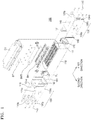
- FIG. 1 is an exploded perspective view illustrating a battery pack cooling device according to an embodiment of the present disclosure
- FIG. 2 is an exploded side view schematically illustrating a coupling structure of a housing, a first sub-housing, and a second sub-housing of the battery pack cooling device shown in FIG. 1 .
- a battery pack cooling device 100 may include a housing 110, a first sub-housing 120, a second sub-housing 130, coupling members 140, a first sealing member 150, and a second sealing member 160.
- the housing 110 may have a box shape to accommodate battery cells C and may include a plurality of flow passages 111 extending in a first direction.
- the flow passages 111 may be formed in the housing 110 in such a manner that the flow passages 111 may extend in the first direction while being arranged on both sides and lower sides of the battery cells C and may be open in the first direction.
- a fluid may flow through the flow passages 111 and may have a function of absorbing heat generated from the battery cells C and dissipating the heat to the outside while flowing through the flow passages 111.
- the fluid may be water or air.
- the battery pack cooling device 100 when water is used as the fluid, the battery pack cooling device 100 may be referred to as a "water cooling type" battery pack cooling device 100, and when air is used as the fluid, the battery pack cooling device 100 may be referred to as an "air cooling type” battery pack cooling device 100.
- a bus bar holder BH which is electrically connected to terminals of the battery cells C, may be coupled to an upper surface of the housing 110, and a battery management system BMS, which includes a circuit for generally managing the charge and discharge operations and safety of the battery cells C, may be coupled to an upper side of the bus bar holder BH.
- the battery management system BMS may be provided with a first terminal member (not shown) which protrudes upward for interconnection with the outside of the battery cells C.
- a baffle plate BP may be provided on an upper side of the battery management system BMS, and in this case, the bus bar holder BH, the battery management system BMS, and the baffle plate BP may respectively include open holes (not shown) such that the bus bar holder BH, the battery management system BMS, and the baffle plate BP may communicate with each other to discharge gas generated from the battery cells C toward a cover CV.
- a relay RL having a function of forming an electrical short circuit between the battery cells C and the bus bar holder BH in an emergency may be provided on a lateral surface of the housing 110, and a second terminal member (not shown) facing the first terminal member in the first direction may be provided on the relay RL.
- the first terminal member and the second terminal member may protrude upward through installation holes (not shown) formed in the cover CV and may respectively function as a positive pole and a negative pole.
- the first sub-housing 120 may be provided on a side of the housing 110 in the first direction
- the second sub-housing 130 may be provided on the other side of the housing 110 in the first direction. That is, the second sub-housing 130 may be opposite the first sub-housing 120 with the housing 110 therebetween in the first direction.
- the first sub-housing 120 may include a first coupling hole 121 communicating with one of the flow passages 111 formed in the housing 110 and a first guide hole 122 communicating with at least one of the flow passages 111.
- the second sub-housing 130 may include a second coupling hole 131 communicating with one of the flow passages 111 and a second guide hole 132 communicating with at least one of the flow passages 111.
- FIGS. 1 and 2 show two first sub-housings 120a and 120b, and two second sub- housings 130a and 130b.
- a pair corresponding to reference numerals 120a and 130a that is, the first sub-housings 120a and the second sub-housings 130a
- the other pair corresponding to reference numerals 120b and 130b that is, the first sub-housing 120b and the second sub-housing 130b
- the first set and the second set may be coupled to the housing 110 in a replaceable manner. That is, when the first sub-housing 120a and the second sub-housing 130a corresponding to the first set are installed on both sides of the housing 110, the battery pack cooling device 100 of the embodiment of the present disclosure may function as a "water cooling type" battery pack cooling device 100 that uses water as a fluid. In addition, when the first sub-housing 120b and the second sub-housing 130b corresponding to the second set are installed on both sides of the housing 110, the battery pack cooling device 100 of the embodiment of the present disclosure may function as an "air cooling type" battery pack cooling device 100 that uses air as a fluid.
- the method of cooling the battery cells C accommodated in the housing 110 may be simply changed by selectively installing, on the housing 110, one of the first set including the first sub-housing 120a and the second sub-housing 130a and the second set including the first sub-housing 120b and the second sub-housing 130b.
- the coupling members 140 may be inserted into the first coupling hole 121 and the second coupling hole 131.
- Each of the coupling members 140 respectively inserted into the first coupling hole 121 and the second coupling hole 131 may close a side of one of the flow passages 111 that communicates with the first coupling hole 121 and the second coupling hole 131.
- the path of a fluid flowing along the flow passages 111 may vary according to the installation positions of the coupling members 140 inserted into the first coupling hole 121 and the second coupling hole 131. This will be described in detail with reference to FIGS. 3 to 7 .
- first sealing member 150 may be placed between the housing 110 and the first sub-housing 120
- second sealing member 160 may be placed between the housing 110 and the second sub-housing 130.
- the first sealing member 150 and the second sealing member 160 are structures for preventing leakage of a fluid between the housing 110 and the first sub-housing 120 or between the housing 110 and the second sub-housing 130 when the fluid flows along the first guide hole 122, the flow passages 111, and the second guide hole 132, or along the second guide hole 132, the flow passages 111, and the first guide hole 122.
- the first sealing member 150 and the second sealing member 160 may include a material having a certain degree of elasticity.
- the first sealing member 150 and the second sealing member 160 include a plurality of communication holes 151 and 161 communicating with the flow passages 111 such that a fluid may flow through the first sealing member 150 and the second sealing member 160.
- the first sealing member 150 (or the second sealing member 160) may be pressed and compressed as the first sub-housing 120 (or the second sub-housing 130) is moved toward the housing 110.
- the compressed first sealing member 150 (or the second sealing member 160) may expand owing to the resilience thereof, and thus a gap between the housing 110 and the first sub-housing 120 (or the second sub-housing 130) may be filled, thereby preventing leakage of a fluid flowing from the housing 110 to the first sub-housing 120 (or the second sub-housing 130).
- FIG. 3 is a cut-away perspective view illustrating a first coupling structure of the battery pack cooling device 100 shown in FIG. 1 in the first direction to illustrate a specific flow of a fluid
- FIG. 5 is a cut-away side view obtained by cutting a lower side of the battery pack cooling device 100 of FIG. 3 in the first direction to illustrate a specific flow of a fluid.
- a water cooling type battery pack cooling device 100 will be described in detail with reference to FIGS. 3 to 5 .
- FIGS. 3 to 5 illustrate the case in which the first sub-housings 120a and the second sub-housing 130a corresponding to the first set of the first sub-housing 120 and the second sub-housing 130 shown in FIG. 1 are respectively installed on both sides of the housing 110.
- a first coupling hole 121a of the first sub-housing 120a and a second coupling hole 131a of the second sub-housing 130a may not be aligned with each other in the first direction.
- a first guide hole 122a of the first sub-housing 120a and a second guide hole 132a of the second sub-housing 130a may partially overlap each other in the first direction.
- the first guide hole 122a and the second guide hole 132a may be arranged to share one flow passage 111.
- the first sub-housing 120a may further include: a first inlet 123a which overlaps at least one of the flow passages 111 in the first direction and into which a fluid is introduced; and a first outlet 124a which overlaps one of the flow passages 111 in the first direction and through which the fluid used to cool the battery cells C is discharged to the outside.
- first inlet 123a and the first outlet 124a may be formed on both sides of the first sub-housing 120a in a second direction crossing the first direction. That is, cooling water may be introduced through the first inlet 123a into one of the flow passages 111 that communicates with the first inlet 123a and may sequentially flow along one side and the other side of the housing 110 through the flow passages 111, and then the cooling water may be discharged through the first outlet 124a.
- FIG. 4 is view obtained by cutting away sides of the first sub-housing 120a, the housing 110, and the second sub-housing 130a to illustrate a specific flow of a fluid flowing along the flow passages 111, the first guide hole 122a, and the second guide hole 132a.
- FIG. 5 is a view in which a fluid introduced through the second guide hole 132a corresponding to reference numeral A flows along a flow passage 111 arranged in a lower side of the housing 110 to another second guide hole 132a corresponding to reference numeral B.
- the flow of the fluid along the other sides of the first sub-housing 120a, the housing 110, and the second sub-housing 130a at which the first outlet 124a is located may be similar to that shown in FIG. 4 , and then as described above, the fluid may be discharged to the outside through the first outlet 124a.
- a fluid is introduced through the first inlet 123a and starts to flow along the flow passage 111 communicating with the first inlet 123a.
- the fluid flows along the flow passage 111, which communicates with the first inlet 123a, toward the second sub-housing 130a and enters the second guide hole 132a of the second sub-housing 130a. Since the second guide hole 132a does not penetrate the second sub-housing 130a, the fluid that has entered the second guide hole 132a flows back toward the first sub-housing 120a along another flow passage 111 different from the flow passage 111 communicating with the first inlet 123a. That is, the fluid introduced into the flow passage 111 through the first inlet 123a may turn once at the second guide hole 132a and may then flow.
- first guide hole 122a overlaps a portion of the second guide hole 132a such that the fluid flowing from the second guide hole 132a to the flow passage 111 may be guided to the first guide hole 122a.
- first guide hole 122a does not penetrate the first sub-housing 120a, the fluid introduced into the first guide hole 122a may turn again and may be then guided toward another second guide hole 132a along another flow passage 111 different from the above-mentioned flow passage 111.
- the fluid introduced through the first inlet 123a may sequentially flow along the first guide hole 122a, the flow passage 111, and the second guide hole 132a, or along the second guide hole 132a, the flow passage 111, and the first guide hole 122a.
- a fluid introduced through the first inlet 123a may turn at least once and may then flow while flowing along one side, a lower side, and the other side of the housing 110, and thereafter, the fluid may be discharged through the first outlet 124a.
- FIG. 6 is a cut-away perspective view illustrating a second coupling structure of the battery pack cooling device 100 shown in FIG. 1 in the first direction to illustrate a specific flow of a fluid
- FIG. 8 is a cut-away side view illustrating another embodiment of the second sub-housing 130b of the battery pack cooling device 100 shown in FIG. 7 .
- an "air cooling type" battery pack cooling device 100 will be described in detail with reference to FIGS. 6 to 8 .
- FIGS. 6 to 8 illustrate the case in which the first sub-housing 120b and the second sub-housing 130b corresponding to the second set of the first sub-housing 120 and the second sub-housing 130 shown in FIG. 1 are respectively installed on both sides of the housing 110.
- a first coupling hole 121b of the first sub-housing 120b and a second coupling hole 131 b of the second sub-housing 130b may overlap each other in the first direction.
- a first guide hole 122b of the first sub-housing 120b may overlap a second guide hole 132b in the first direction.
- the first sub-housing 120b may include the first guide hole 122b which penetrates the first sub-housing 120b in the first direction and functions as an inlet through which a fluid is introduced.
- the first sub-housing 120b may include a plurality of first guide holes 122b, and a fluid may be introduced into the flow passages 111 of the housing 110 through the first guide holes 122b.
- first guide hole 122b may be partially open in the second direction. Owing to this structure, a portion of a fluid introduced through the first guide hole 122b may flow along flow passages 111 in the first direction, and another portion of the fluid may be guided in the second direction to a first internal chamber 123b provided in the first sub-housing 120b. The other portion of the fluid guided to the first internal chamber 123b may flow to an empty space formed in the cover CV of a battery pack (not shown) and may then be guided in the first direction to the second sub-housing 130b and a second internal chamber 133b of the second sub-housing 130b.
- the second guide hole 132b may not penetrate the second sub-housing 130b in the first direction (refer to FIGS. 6 and 7 ).
- the second guide hole 132b may be partially open in the second direction such that a fluid delivered from the flow passages 111 to the second guide hole 132b may flow in the second direction and may be guided to the second internal chamber 133b provided in the second sub-housing 130b.
- the second guide hole 132b may further include a second outlet 134b to discharge the fluid to the outside.
- the battery cells C when the battery cells C are cooled with air, air introduced through the first guide hole 122b may be guided to the second guide hole 132b through the flow passages 111 and collected in the second internal chamber 133b, and the air collected in the second internal chamber 133b may be discharged to the outside through the second outlet 134b. That is, when the first sub-housing 120b and the second sub-housing 130b corresponding to the second set are respectively installed on both sides of the housing 110 to use air as a cooling fluid, the fluid introduced through the first guide hole 122b may cool the battery cells C while flowing straight along the flow passages 111 in the first direction to the second guide hole 132b.
- the "air cooling type" battery pack cooling device 100 may further include a blower member 170 (refer to FIG. 1 ) to force the fluid to flow.
- the blower member 170 may be provided in at least one of the first internal chamber 123b and the second internal chamber 133b.
- the blower member 170 is installed in the second internal chamber 133b of the second sub-housing 130b in which the second outlet 134b is formed.
- embodiments of the present disclosure are not limited thereto, and the blower member 170 may be installed in the first internal chamber 123b of the first sub-housing 120b.
- the second outlet 134b of the second sub-housing 130b may be open in the second direction.
- the reason for this structure is to improve ease of design by equal-direction installation because an outlet (not shown) of the blower member 170 is oriented to discharge the fluid in the second direction.
- the second outlet 134b may be open in the first direction.
- the second outlet 134b may be open in a third direction crossing the first and second directions.
- the reason for this is that it is possible to discharge the fluid collected in the second internal chamber 133b in any direction.
- the fluid introduced through the first guide hole 122b absorbs heat generated at the battery cells C while flowing along the flow passages 111, and then the fluid is collected in the second internal chamber 133b through the second guide hole 132b.
- the main function of the second outlet 134b is to discharge the fluid collected in the second internal chamber 133b to the outside, it is unnecessary to limit the direction in which the fluid is discharged through the second outlet 134b.
- a second guide hole 132c may penetrate the second sub-housings 130c in the first direction.
- a fluid introduced through a first guide hole 122c and having passed through flow passages 111 may be discharged to the outside through the second guide hole 132c. That is, the second guide hole 132c may have the same function as the second outlet 134b shown in FIGS. 6 and 7 .
- the second outlet 134b that is shown in FIGS. 6 and 7 and the second guide hole 132c that is shown in FIG. 8 and functions as an outlet may have a common structure (not shown). That is, even in a state in which the second outlet 134b is formed in the second sub-housing 130b as shown in FIG. 6 and 7 , the second guide hole 132b may penetrate the second sub-housing 130b in the first direction. In this structure, a fluid introduced through the second guide hole 132b may be collected in the second internal chamber 133b and may be discharged to the outside through the second outlet 134b and also through the second guide hole 132b.
- a water cooling type and an air cooling type which are main types for cooling the battery cells C may be selectively applied to the housing 110. That is, the flow passages 111, which are commonly used in the water cooling type and the air cooling type, are formed in the housing 110, and the first sub-housing 120 and the second sub-housing 130 are installed on both sides of the housing 110 in a replaceable manner such that the water cooling type and the air cooling type may be selectively implemented.
- the water cooling type and the air cooling type may be selectively applied according to a required degree of cooling performance for the battery cells C, thereby reducing the number and total weight of necessary components and a space for installing components.
- the first and second sub-housings having different structures may be installed on lateral sides of the housing in a replaceable manner according to a required degree of cooling performance for the battery cells, and thus, cooling methods may be selectively applied.
Abstract
Description
- Embodiments of the present disclosure relate to a device for cooling a battery pack.
- Unlike primary batteries, secondary batteries are rechargeable and are widely used in small high-tech electronic devices such as cellular phones, PDAs, and laptop computers, and energy storage systems as well.
- When a secondary battery is charged and discharged, heat is generated from the secondary battery, and thus, if such a secondary battery is not properly cooled, cells of the secondary battery may be damaged such that internal materials may leak or the cells may explode in severe cases.
- The above-described background art is technical information that the inventor had or learned when or while deriving embodiments of the present disclosure and may not have been publicly known before the filing of the present application.
- Embodiments of the present disclosure provide battery pack cooling devices configured to easily change a cooling method according to a required degree of cooling performance for a battery pack by improving the structure of a housing.
- An embodiment of the present disclosure provides a device for cooling a battery pack, the device including: a housing including a plurality of flow passages extending in a first direction; a first sub-housing provided on the housing in the first direction; and a second sub-housing arranged opposite the first sub-housing in the first direction and provided on the housing, wherein the first sub-housing includes a first coupling hole communicating with one of the plurality of flow passages and a first guide hole communicating with at least one of the plurality of flow passages, the second sub-housing includes a second coupling hole communicating with one of the plurality of flow passages and a second guide hole communicating with at least one of the plurality of flow passages, and a path of a fluid flowing in the plurality of flow passages variesaccording to installation positions of coupling members inserted into the first and second coupling holes.
- According to the battery pack cooling device of embodiments of the present disclosure, the first and second sub-housings having different structures may be installed on lateral sides of the housing in a replaceable manner according to a required degree of cooling performance for battery cells, and thus cooling methods may be selectively applied.
- However, the scope of the present disclosure is not limited to these effects.
-
-
FIG. 1 is an exploded perspective view illustrating a battery pack cooling device according to an embodiment of the present disclosure. -
FIG. 2 is an exploded side view schematically illustrating a coupling structure of a housing, a first sub-housing, and a second sub-housing of the battery pack cooling device shown inFIG. 1 . -
FIG. 3 is a cut-away perspective view illustrating a first coupling structure of the battery pack cooling device shown inFIG. 1 . -
FIG. 4 is a cut-away side view obtained by cutting a lateral side of the battery pack cooling device ofFIG. 3 in a first direction to illustrate a specific flow of a fluid. -
FIG. 5 is a cut-away side view obtained by cutting a lower side of the battery pack cooling device ofFIG. 3 in the first direction to illustrate a specific flow of a fluid. -
FIG. 6 is a cut-away perspective view illustrating a second coupling structure of the battery pack cooling device shown inFIG. 1 . -
FIG. 7 is a cut-away side view obtained by cutting a lateral side of the battery pack cooling device ofFIG. 6 in the first direction to illustrate a specific flow of a fluid. -
FIG. 8 is a cut-away side view illustrating another embodiment of the second sub-housing of the battery pack cooling device shown inFIG. 7 . - An embodiment of the present disclosure provides a device for cooling a battery pack, the device including: a housing including a plurality of flow passages extending in a first direction; a first sub-housing provided on the housing in the first direction; and a second sub-housing arranged opposite the first sub-housing in the first direction and provided on the housing, wherein the first sub-housing includes a first coupling hole communicating with one of the plurality of flow passages and a first guide hole communicating with at least one of the plurality of flow passages, the second sub-housing includes a second coupling hole communicating with one of the plurality of flow passages and a second guide hole communicating with at least one of the plurality of flow passages, and a path of a fluid flowing in the plurality of flow passages varies according to installation positions of coupling members inserted into the first and second coupling holes.
- In the embodiment, the device may further include: a first sealing member between the housing and the first sub-housing; and a second sealing member between the housing and the second sub-housing.
- In the embodiment, the first and second sealing members may include a plurality of communication holes that communicate with the plurality of flow passages.
- In the embodiment, the first and second coupling holes may not be aligned with each other in the first direction.
- In the embodiment, the first sub-housing may further include: a first inlet through which the fluid is introduced and which overlaps at least one of the plurality of flow passages in the first direction; and a first outlet through which the fluid is discharged and which overlaps at least one of the plurality of flow passages in the first direction, wherein the first inlet and the first outlet may be provided on both sides of the first sub-housing in a second direction crossing the first direction.
- In the embodiment, the first and second guide holes partially may overlap each other in the first direction.
- In the embodiment, the first guide may not penetrate the first sub-housing, and the second guide hole may not penetrate the second sub-housing.
- In the embodiment, the first and second coupling holes may overlap each other in the first direction, and the first and second guide holes may overlap each other in the first direction.
- In the embodiment, the first guide hole may penetrate the first sub-housing in the first direction and may be partially open in a second direction crossing the first direction such that a portion of the fluid introduced into the first guide hole may be guided to some of the plurality of flow passages in the first direction and another portion of the fluid introduced into the first guide hole may be guided in the second direction to a first internal chamber provided in the first sub-housing, and the second guide hole may penetrate the second sub-housing in the first direction and may be partially open in the second direction such that a portion of the fluid delivered from the plurality of flow passages to the second guide hole may be discharged outside and another portion of the fluid delivered from the plurality of flow passages to the second guide hole may be guided to a second internal chamber provided in the second sub-housing.
- In the embodiment, the second sub-housing may further include a second outlet through which the fluid is discharged outside, wherein the first guide hole may penetrate the first sub-housing in the first direction and may be partially open in a second direction crossing the first direction such that a portion of the fluid introduced into the first guide hole may be guided to some of the plurality of flow passages in the first direction and another portion of the fluid introduced into the first guide hole may be guided in the second direction to a first internal chamber provided in the first sub-housing, the second guide hole may not penetrate the second sub-housing in the first direction and may be partially open in the second direction such that the fluid delivered from the plurality of flow passages to the second guide hole may be guided to a second internal chamber provided in the second sub-housing, and the fluid collected in the second internal chamber may be discharged outside through the second outlet.
- In the embodiment, the device may further include a blower member provided in at least one of the first and second internal chambers.
- Another embodiment of the present disclosure provides a device for cooling a battery pack, the device including: a housing including a plurality of flow passages extending in a first direction; a first sub-housing provided on the housing in the first direction; and a second sub-housing arranged opposite the first sub-housing in the first direction and provided on the housing, wherein the first sub-housing includes a first coupling hole communicating with one of the plurality of flow passages and a first guide hole communicating with at least one of the plurality of flow passages, the second sub-housing includes a second coupling hole communicating with one of the plurality of flow passages and a second guide hole communicating with at least one of the plurality of flow passages, and a coupling member is inserted into at least one of the plurality of flow passages to connect together the plurality of flow passages, the first guide hole, and the second guide hole in such a manner that a fluid turns at least once while flowing therein.
- Another embodiment of the present disclosure provides a device for cooling a battery pack, the device including: a housing including a plurality of flow passages extending in a first direction; a first sub-housing provided on the housing in the first direction; and a second sub-housing arranged opposite the first sub-housing in the first direction and provided on the housing, wherein the first sub-housing includes a first coupling hole communicating with one of the plurality of flow passages and a first guide hole communicating with at least one of the plurality of flow passages, the second sub-housing includes a second coupling hole communicating with one of the plurality of flow passages and a second guide hole communicating with at least one of the plurality of flow passages, and a coupling member is inserted into at least one of the plurality of flow passages to connect together the first guide hole, the plurality of flow passages, and the second guide hole in such a manner that a fluid flows straight in the first direction.
- Other aspects, characteristics, and advantages will become apparent and more readily appreciated from the accompanying drawings, claims, and detailed description.
- The present disclosure may be variously modified, and various embodiments may be provided according to the present disclosure. Hereinafter, some embodiments will be illustrated in the accompanying drawings and described in detail. Effects and features of the present disclosure, and implementation methods thereof will be clarified through the following embodiments described in detail with reference to the accompanying drawings. However, the present disclosure is not limited to the following embodiments but may be implemented in various forms.
- In the following embodiments, it will be understood that although terms such as "first" and "second" are used to describe various elements, these elements should not be limited by these terms. These terms are only used to distinguish one element from another. The terms of a singular form may include plural forms unless referred to the contrary. In addition, terms such as "include" or "comprise" specify features or the presence of stated elements, but do not exclude other features or elements.
- In the drawings, the sizes of elements may be exaggerated for clarity. For example, in the drawings, the size or thickness of each element may be arbitrarily shown for illustrative purposes, and thus the present disclosure should not be construed as being limited thereto.
- Hereinafter, embodiments of the present disclosure will be described in detail with reference to the accompanying drawings. In the following description given with reference to the accompanying drawings, the same elements or corresponding elements are denoted with the same reference numerals, and overlapping descriptions thereof will be omitted.
-
FIG. 1 is an exploded perspective view illustrating a battery pack cooling device according to an embodiment of the present disclosure, andFIG. 2 is an exploded side view schematically illustrating a coupling structure of a housing, a first sub-housing, and a second sub-housing of the battery pack cooling device shown inFIG. 1 . - Referring to
FIGS. 1 and2 , according to the embodiment of the present disclosure, a batterypack cooling device 100 may include ahousing 110, afirst sub-housing 120, asecond sub-housing 130,coupling members 140, afirst sealing member 150, and asecond sealing member 160. - The
housing 110 may have a box shape to accommodate battery cells C and may include a plurality offlow passages 111 extending in a first direction. Theflow passages 111 may be formed in thehousing 110 in such a manner that theflow passages 111 may extend in the first direction while being arranged on both sides and lower sides of the battery cells C and may be open in the first direction. A fluid may flow through theflow passages 111 and may have a function of absorbing heat generated from the battery cells C and dissipating the heat to the outside while flowing through theflow passages 111. - Here, the fluid may be water or air. For example, when water is used as the fluid, the battery
pack cooling device 100 may be referred to as a "water cooling type" batterypack cooling device 100, and when air is used as the fluid, the batterypack cooling device 100 may be referred to as an "air cooling type" batterypack cooling device 100. - A bus bar holder BH, which is electrically connected to terminals of the battery cells C, may be coupled to an upper surface of the
housing 110, and a battery management system BMS, which includes a circuit for generally managing the charge and discharge operations and safety of the battery cells C, may be coupled to an upper side of the bus bar holder BH. The battery management system BMS may be provided with a first terminal member (not shown) which protrudes upward for interconnection with the outside of the battery cells C. A baffle plate BP may be provided on an upper side of the battery management system BMS, and in this case, the bus bar holder BH, the battery management system BMS, and the baffle plate BP may respectively include open holes (not shown) such that the bus bar holder BH, the battery management system BMS, and the baffle plate BP may communicate with each other to discharge gas generated from the battery cells C toward a cover CV. - In addition, a relay RL having a function of forming an electrical short circuit between the battery cells C and the bus bar holder BH in an emergency may be provided on a lateral surface of the
housing 110, and a second terminal member (not shown) facing the first terminal member in the first direction may be provided on the relay RL. In this case, the first terminal member and the second terminal member may protrude upward through installation holes (not shown) formed in the cover CV and may respectively function as a positive pole and a negative pole. - The
first sub-housing 120 may be provided on a side of thehousing 110 in the first direction, and thesecond sub-housing 130 may be provided on the other side of thehousing 110 in the first direction. That is, thesecond sub-housing 130 may be opposite thefirst sub-housing 120 with thehousing 110 therebetween in the first direction. - Specifically, the
first sub-housing 120 may include a first coupling hole 121 communicating with one of theflow passages 111 formed in thehousing 110 and a first guide hole 122 communicating with at least one of theflow passages 111. - In addition, the
second sub-housing 130 may include a second coupling hole 131 communicating with one of theflow passages 111 and a second guide hole 132 communicating with at least one of theflow passages 111. -
FIGS. 1 and2 show two first sub-housings 120a and 120b, and two second sub-housings numerals numerals - As will be described in detail below, the first set and the second set may be coupled to the
housing 110 in a replaceable manner. That is, when the first sub-housing 120a and the second sub-housing 130a corresponding to the first set are installed on both sides of thehousing 110, the batterypack cooling device 100 of the embodiment of the present disclosure may function as a "water cooling type" batterypack cooling device 100 that uses water as a fluid. In addition, when the first sub-housing 120b and the second sub-housing 130b corresponding to the second set are installed on both sides of thehousing 110, the batterypack cooling device 100 of the embodiment of the present disclosure may function as an "air cooling type" batterypack cooling device 100 that uses air as a fluid. - That is, according to the configuration of the battery
pack cooling device 100 of the embodiment of the present disclosure, the method of cooling the battery cells C accommodated in thehousing 110 may be simply changed by selectively installing, on thehousing 110, one of the first set including the first sub-housing 120a and the second sub-housing 130a and the second set including the first sub-housing 120b and the second sub-housing 130b. - The
coupling members 140 may be inserted into the first coupling hole 121 and the second coupling hole 131. Each of thecoupling members 140 respectively inserted into the first coupling hole 121 and the second coupling hole 131 may close a side of one of theflow passages 111 that communicates with the first coupling hole 121 and the second coupling hole 131. According to this structure, the path of a fluid flowing along theflow passages 111 may vary according to the installation positions of thecoupling members 140 inserted into the first coupling hole 121 and the second coupling hole 131. This will be described in detail with reference toFIGS. 3 to 7 . - In addition, the
first sealing member 150 may be placed between thehousing 110 and thefirst sub-housing 120, and thesecond sealing member 160 may be placed between thehousing 110 and thesecond sub-housing 130. - The
first sealing member 150 and thesecond sealing member 160 are structures for preventing leakage of a fluid between thehousing 110 and thefirst sub-housing 120 or between thehousing 110 and thesecond sub-housing 130 when the fluid flows along the first guide hole 122, theflow passages 111, and the second guide hole 132, or along the second guide hole 132, theflow passages 111, and the first guide hole 122. Thefirst sealing member 150 and thesecond sealing member 160 may include a material having a certain degree of elasticity. In addition, thefirst sealing member 150 and thesecond sealing member 160 include a plurality ofcommunication holes flow passages 111 such that a fluid may flow through thefirst sealing member 150 and thesecond sealing member 160. - In detail, when the
housing 110 and the first sub-housing 120 (or the second sub-housing 130) are coupled to each other using thecoupling member 140, the first sealing member 150 (or the second sealing member 160) may be pressed and compressed as the first sub-housing 120 (or the second sub-housing 130) is moved toward thehousing 110. The compressed first sealing member 150 (or the second sealing member 160) may expand owing to the resilience thereof, and thus a gap between thehousing 110 and the first sub-housing 120 (or the second sub-housing 130) may be filled, thereby preventing leakage of a fluid flowing from thehousing 110 to the first sub-housing 120 (or the second sub-housing 130). -
FIG. 3 is a cut-away perspective view illustrating a first coupling structure of the batterypack cooling device 100 shown inFIG. 1 in the first direction to illustrate a specific flow of a fluid, andFIG. 5 is a cut-away side view obtained by cutting a lower side of the batterypack cooling device 100 ofFIG. 3 in the first direction to illustrate a specific flow of a fluid. Hereinafter, the configuration and operation of a "water cooling type" batterypack cooling device 100 will be described in detail with reference toFIGS. 3 to 5 . -
FIGS. 3 to 5 illustrate the case in which the first sub-housings 120a and the second sub-housing 130a corresponding to the first set of thefirst sub-housing 120 and thesecond sub-housing 130 shown inFIG. 1 are respectively installed on both sides of thehousing 110. - Specifically, referring to
FIGS. 3 to 5 , afirst coupling hole 121a of the first sub-housing 120a and asecond coupling hole 131a of the second sub-housing 130a may not be aligned with each other in the first direction. In addition, afirst guide hole 122a of the first sub-housing 120a and asecond guide hole 132a of the second sub-housing 130a may partially overlap each other in the first direction. Specifically, thefirst guide hole 122a and thesecond guide hole 132a may be arranged to share oneflow passage 111. - In addition, the first sub-housing 120a may further include: a
first inlet 123a which overlaps at least one of theflow passages 111 in the first direction and into which a fluid is introduced; and afirst outlet 124a which overlaps one of theflow passages 111 in the first direction and through which the fluid used to cool the battery cells C is discharged to the outside. - Here, the
first inlet 123a and thefirst outlet 124a may be formed on both sides of the first sub-housing 120a in a second direction crossing the first direction. That is, cooling water may be introduced through thefirst inlet 123a into one of theflow passages 111 that communicates with thefirst inlet 123a and may sequentially flow along one side and the other side of thehousing 110 through theflow passages 111, and then the cooling water may be discharged through thefirst outlet 124a. -
FIG. 4 is view obtained by cutting away sides of the first sub-housing 120a, thehousing 110, and the second sub-housing 130a to illustrate a specific flow of a fluid flowing along theflow passages 111, thefirst guide hole 122a, and thesecond guide hole 132a. In addition,FIG. 5 is a view in which a fluid introduced through thesecond guide hole 132a corresponding to reference numeral A flows along aflow passage 111 arranged in a lower side of thehousing 110 to anothersecond guide hole 132a corresponding to reference numeral B. In addition, although not shown in the drawings, the flow of the fluid along the other sides of the first sub-housing 120a, thehousing 110, and the second sub-housing 130a at which thefirst outlet 124a is located may be similar to that shown inFIG. 4 , and then as described above, the fluid may be discharged to the outside through thefirst outlet 124a. - Referring to
FIG. 4 , a fluid is introduced through thefirst inlet 123a and starts to flow along theflow passage 111 communicating with thefirst inlet 123a. The fluid flows along theflow passage 111, which communicates with thefirst inlet 123a, toward the second sub-housing 130a and enters thesecond guide hole 132a of the second sub-housing 130a. Since thesecond guide hole 132a does not penetrate the second sub-housing 130a, the fluid that has entered thesecond guide hole 132a flows back toward the first sub-housing 120a along anotherflow passage 111 different from theflow passage 111 communicating with thefirst inlet 123a. That is, the fluid introduced into theflow passage 111 through thefirst inlet 123a may turn once at thesecond guide hole 132a and may then flow. - As described above, a portion of the
first guide hole 122a overlaps a portion of thesecond guide hole 132a such that the fluid flowing from thesecond guide hole 132a to theflow passage 111 may be guided to thefirst guide hole 122a. In addition, since thefirst guide hole 122a does not penetrate the first sub-housing 120a, the fluid introduced into thefirst guide hole 122a may turn again and may be then guided toward anothersecond guide hole 132a along anotherflow passage 111 different from the above-mentionedflow passage 111. In this manner, the fluid introduced through thefirst inlet 123a may sequentially flow along thefirst guide hole 122a, theflow passage 111, and thesecond guide hole 132a, or along thesecond guide hole 132a, theflow passage 111, and thefirst guide hole 122a. - That is, as shown in
FIGS. 3 to 5 , when the batterypack cooling device 100 of the embodiment of the present disclosure has the first coupling structure, that is, when the first sub-housing 120a and the second sub-housing 130a of the first set are coupled to both sides of thehousing 110, a fluid introduced through thefirst inlet 123a may turn at least once and may then flow while flowing along one side, a lower side, and the other side of thehousing 110, and thereafter, the fluid may be discharged through thefirst outlet 124a. -
FIG. 6 is a cut-away perspective view illustrating a second coupling structure of the batterypack cooling device 100 shown inFIG. 1 in the first direction to illustrate a specific flow of a fluid, andFIG. 8 is a cut-away side view illustrating another embodiment of the second sub-housing 130b of the batterypack cooling device 100 shown inFIG. 7 . Hereinafter, the configuration and operation of an "air cooling type" batterypack cooling device 100 will be described in detail with reference toFIGS. 6 to 8 . -
FIGS. 6 to 8 illustrate the case in which the first sub-housing 120b and the second sub-housing 130b corresponding to the second set of thefirst sub-housing 120 and thesecond sub-housing 130 shown inFIG. 1 are respectively installed on both sides of thehousing 110. - Specifically, referring to
FIGS. 6 to 8 , afirst coupling hole 121b of the first sub-housing 120b and asecond coupling hole 131 b of the second sub-housing 130b may overlap each other in the first direction. In addition, afirst guide hole 122b of the first sub-housing 120b may overlap asecond guide hole 132b in the first direction. - The first sub-housing 120b may include the
first guide hole 122b which penetrates the first sub-housing 120b in the first direction and functions as an inlet through which a fluid is introduced. For example, as shown inFIGS. 6 and7 , the first sub-housing 120b may include a plurality offirst guide holes 122b, and a fluid may be introduced into theflow passages 111 of thehousing 110 through the first guide holes 122b. - In addition, the
first guide hole 122b may be partially open in the second direction. Owing to this structure, a portion of a fluid introduced through thefirst guide hole 122b may flow alongflow passages 111 in the first direction, and another portion of the fluid may be guided in the second direction to a firstinternal chamber 123b provided in the first sub-housing 120b. The other portion of the fluid guided to the firstinternal chamber 123b may flow to an empty space formed in the cover CV of a battery pack (not shown) and may then be guided in the first direction to the second sub-housing 130b and a secondinternal chamber 133b of the second sub-housing 130b. - The
second guide hole 132b may not penetrate the second sub-housing 130b in the first direction (refer toFIGS. 6 and7 ). In addition, thesecond guide hole 132b may be partially open in the second direction such that a fluid delivered from theflow passages 111 to thesecond guide hole 132b may flow in the second direction and may be guided to the secondinternal chamber 133b provided in the second sub-housing 130b. In addition, thesecond guide hole 132b may further include asecond outlet 134b to discharge the fluid to the outside. - According to this structure, when the battery cells C are cooled with air, air introduced through the
first guide hole 122b may be guided to thesecond guide hole 132b through theflow passages 111 and collected in the secondinternal chamber 133b, and the air collected in the secondinternal chamber 133b may be discharged to the outside through thesecond outlet 134b. That is, when the first sub-housing 120b and the second sub-housing 130b corresponding to the second set are respectively installed on both sides of thehousing 110 to use air as a cooling fluid, the fluid introduced through thefirst guide hole 122b may cool the battery cells C while flowing straight along theflow passages 111 in the first direction to thesecond guide hole 132b. - In addition, the "air cooling type" battery
pack cooling device 100 may further include a blower member 170 (refer toFIG. 1 ) to force the fluid to flow. Theblower member 170 may be provided in at least one of the firstinternal chamber 123b and the secondinternal chamber 133b. For example, referring toFIG. 1 , theblower member 170 is installed in the secondinternal chamber 133b of the second sub-housing 130b in which thesecond outlet 134b is formed. However, embodiments of the present disclosure are not limited thereto, and theblower member 170 may be installed in the firstinternal chamber 123b of the first sub-housing 120b. - In detail, referring to
FIG. 6 , thesecond outlet 134b of the second sub-housing 130b may be open in the second direction. The reason for this structure is to improve ease of design by equal-direction installation because an outlet (not shown) of theblower member 170 is oriented to discharge the fluid in the second direction. However, this is an example, and thesecond outlet 134b may be open in the first direction. In addition, besides the first and second directions, thesecond outlet 134b may be open in a third direction crossing the first and second directions. - The reason for this is that it is possible to discharge the fluid collected in the second
internal chamber 133b in any direction. The fluid introduced through thefirst guide hole 122b absorbs heat generated at the battery cells C while flowing along theflow passages 111, and then the fluid is collected in the secondinternal chamber 133b through thesecond guide hole 132b. In this case, since the main function of thesecond outlet 134b is to discharge the fluid collected in the secondinternal chamber 133b to the outside, it is unnecessary to limit the direction in which the fluid is discharged through thesecond outlet 134b. - For example, referring to
FIG. 8 , asecond guide hole 132c may penetrate the second sub-housings 130c in the first direction. In this case, a fluid introduced through afirst guide hole 122c and having passed throughflow passages 111 may be discharged to the outside through thesecond guide hole 132c. That is, thesecond guide hole 132c may have the same function as thesecond outlet 134b shown inFIGS. 6 and7 . - The
second outlet 134b that is shown inFIGS. 6 and7 and thesecond guide hole 132c that is shown inFIG. 8 and functions as an outlet may have a common structure (not shown). That is, even in a state in which thesecond outlet 134b is formed in the second sub-housing 130b as shown inFIG. 6 and7 , thesecond guide hole 132b may penetrate the second sub-housing 130b in the first direction. In this structure, a fluid introduced through thesecond guide hole 132b may be collected in the secondinternal chamber 133b and may be discharged to the outside through thesecond outlet 134b and also through thesecond guide hole 132b. - In the battery
pack cooling device 100 having the above-described structure according to the embodiments of the present disclosure, a water cooling type and an air cooling type which are main types for cooling the battery cells C may be selectively applied to thehousing 110. That is, theflow passages 111, which are commonly used in the water cooling type and the air cooling type, are formed in thehousing 110, and thefirst sub-housing 120 and thesecond sub-housing 130 are installed on both sides of thehousing 110 in a replaceable manner such that the water cooling type and the air cooling type may be selectively implemented. - Owing to this structure, the water cooling type and the air cooling type may be selectively applied according to a required degree of cooling performance for the battery cells C, thereby reducing the number and total weight of necessary components and a space for installing components.
- While embodiments of the present disclosure have been described with reference to the accompanying drawings, these embodiments are for illustrative purposes only, and it will be understood by those of ordinary skill in the art that various changes and modifications may be made therefrom. Therefore, the scope and spirit of the present disclosure should be defined by the following claims.
- As described above, according to the battery pack cooling device of the embodiments of the present disclosure, the first and second sub-housings having different structures may be installed on lateral sides of the housing in a replaceable manner according to a required degree of cooling performance for the battery cells, and thus, cooling methods may be selectively applied.
Claims (13)
- A device for cooling a battery pack, the device comprising:a housing comprising a plurality of flow passages extending in a first direction;a first sub-housing provided on the housing in the first direction; anda second sub-housing arranged opposite the first sub-housing in the first direction and provided on the housing,wherein the first sub-housing comprises a first coupling hole communicating with one of the plurality of flow passages and a first guide hole communicating with at least one of the plurality of flow passages,the second sub-housing comprises a second coupling hole communicating with one of the plurality of flow passages and a second guide hole communicating with at least one of the plurality of flow passages, anda path of a fluid flowing in the plurality of flow passages varies according to installation positions of coupling members inserted into the first and second coupling holes.
- The device of claim 1, further comprising:a first sealing member between the housing and the first sub-housing; anda second sealing member between the housing and the second sub-housing.
- The device of claim 2, wherein
the first and second sealing members comprise a plurality of communication holes that communicate with the plurality of flow passages. - The device of claim 1, wherein
the first and second coupling holes are not aligned with each other in the first direction. - The device of claim 1, wherein
the first sub-housing further comprises:a first inlet through which the fluid is introduced and which overlaps at least one of the plurality of flow passages in the first direction; anda first outlet through which the fluid is discharged and which overlaps at least one of the plurality of flow passages in the first direction,wherein the first inlet and the first outlet are provided on both sides of the first sub-housing in a second direction crossing the first direction. - The device of claim 1, wherein
the first and second guide holes partially overlap each other in the first direction. - The device of claim 1, whereinthe first guide hole does not penetrate the first sub-housing, andthe second guide hole does not penetrate the second sub-housing.
- The device of claim 1, wherein
the first and second coupling holes overlap each other in the first direction, and
the first and second guide holes overlap each other in the first direction. - The device of claim 1, whereinthe first guide hole penetrates the first sub-housing in the first direction and is partially open in a second direction crossing the first direction such that a portion of the fluid introduced into the first guide hole is guided to some of the plurality of flow passages in the first direction and another portion of the fluid introduced into the first guide hole is guided in the second direction to a first internal chamber provided in the first sub-housing, andthe second guide hole penetrates the second sub-housing in the first direction and is partially open in the second direction such that a portion of the fluid delivered from the plurality of flow passages to the second guide hole is discharged outside and another portion of the fluid delivered from the plurality of flow passages to the second guide hole is guided to a second internal chamber provided in the second sub-housing.
- The device of claim 1, wherein
the second sub-housing further comprises a second outlet through which the fluid is discharged outside,
wherein the first guide hole penetrates the first sub-housing in the first direction and is partially open in a second direction crossing the first direction such that a portion of the fluid introduced into the first guide hole is guided to some of the plurality of flow passages in the first direction and another portion of the fluid introduced into the first guide hole is guided in the second direction to a first internal chamber provided in the first sub-housing,
the second guide hole does not penetrate the second sub-housing in the first direction and is partially open in the second direction such that the fluid delivered from the plurality of flow passages to the second guide hole is guided to a second internal chamber provided in the second sub-housing, and
the fluid collected in the second internal chamber is discharged outside through the second outlet. - The device of claim 10, further comprising
a blower member provided in at least one of the first and second internal chambers. - A device for cooling a battery pack, the device comprising:a housing comprising a plurality of flow passages extending in a first direction;a first sub-housing provided on the housing in the first direction; anda second sub-housing arranged opposite the first sub-housing in the first direction and provided on the housing,wherein the first sub-housing comprises a first coupling hole communicating with one of the plurality of flow passages and a first guide hole communicating with at least one of the plurality of flow passages,the second sub-housing comprises a second coupling hole communicating with one of the plurality of flow passages and a second guide hole communicating with at least one of the plurality of flow passages, anda coupling member is inserted into at least one of the plurality of flow passages to connect together the plurality of flow passages, the first guide hole, and the second guide hole in such a manner that a fluid turns at least once while flowing therein.
- A device for cooling a battery pack, the device comprising:a housing comprising a plurality of flow passages extending in a first direction;a first sub-housing provided on the housing in the first direction; anda second sub-housing arranged opposite the first sub-housing in the first direction and provided on the housing,wherein the first sub-housing comprises a first coupling hole communicating with one of the plurality of flow passages and a first guide hole communicating with at least one of the plurality of flow passages,the second sub-housing comprises a second coupling hole communicating with one of the plurality of flow passages and a second guide hole communicating with at least one of the plurality of flow passages, anda coupling member is inserted into at least one of the plurality of flow passages to connect together the first guide hole, the plurality of flow passages, and the second guide hole in such a manner that a fluid flows straight in the first direction.
Applications Claiming Priority (2)
| Application Number | Priority Date | Filing Date | Title |
|---|---|---|---|
| KR1020170035509A KR102331723B1 (en) | 2017-03-21 | 2017-03-21 | colling apparatus for battery pack |
| PCT/KR2018/001267 WO2018174400A1 (en) | 2017-03-21 | 2018-01-30 | Device for cooling battery pack |
Publications (2)
| Publication Number | Publication Date |
|---|---|
| EP3576217A1 true EP3576217A1 (en) | 2019-12-04 |
| EP3576217A4 EP3576217A4 (en) | 2020-12-02 |
Family
ID=63585502
Family Applications (1)
| Application Number | Title | Priority Date | Filing Date |
|---|---|---|---|
| EP18770395.4A Pending EP3576217A4 (en) | 2017-03-21 | 2018-01-30 | Device for cooling battery pack |
Country Status (5)
| Country | Link |
|---|---|
| US (1) | US11355798B2 (en) |
| EP (1) | EP3576217A4 (en) |
| KR (1) | KR102331723B1 (en) |
| CN (1) | CN110476297B (en) |
| WO (1) | WO2018174400A1 (en) |
Families Citing this family (2)
| Publication number | Priority date | Publication date | Assignee | Title |
|---|---|---|---|---|
| KR20210059306A (en) | 2019-11-15 | 2021-05-25 | 에스케이이노베이션 주식회사 | Battery thermal management system using variable cooling flow path |
| CN111162208A (en) * | 2019-12-31 | 2020-05-15 | 安徽星玛新能源有限公司 | Battery pack with waterproof function |
Family Cites Families (24)
| Publication number | Priority date | Publication date | Assignee | Title |
|---|---|---|---|---|
| JP5183171B2 (en) | 2007-11-28 | 2013-04-17 | 三洋電機株式会社 | Battery system |
| DE102008027293A1 (en) * | 2008-06-06 | 2009-12-10 | Behr Gmbh & Co. Kg | Device for cooling a vehicle battery |
| JP5428273B2 (en) * | 2008-10-08 | 2014-02-26 | トヨタ自動車株式会社 | Battery temperature control device |
| KR101243908B1 (en) * | 2010-10-12 | 2013-03-14 | 삼성에스디아이 주식회사 | Battery unit and battery module |
| DE102011002666A1 (en) * | 2011-01-13 | 2012-07-19 | Continental Automotive Gmbh | Heat sink for electrical energy storage device used in vehicle, has flow channel for fluid, and side surface for contacting electrical energy storage device |
| DE102011104433A1 (en) * | 2011-01-25 | 2012-07-26 | Bayerische Motoren Werke Aktiengesellschaft | Energy storage module for a device for power supply and method for producing such an energy storage module |
| KR20130005004A (en) | 2011-07-05 | 2013-01-15 | 한라공조주식회사 | Device for cooling battery |
| KR20130025244A (en) | 2011-09-01 | 2013-03-11 | (주)브이이엔에스 | Electric vehicle |
| KR101325201B1 (en) * | 2012-05-10 | 2013-11-04 | (주)에프엠산업 | Battery pack for electric vehicle |
| JP6238106B2 (en) * | 2013-04-08 | 2017-11-29 | 株式会社Gsユアサ | Power storage module, power storage device, and air path connecting member |
| KR20140127393A (en) * | 2013-04-24 | 2014-11-04 | 삼성에스디아이 주식회사 | Battery pack |
| KR101749190B1 (en) | 2013-05-29 | 2017-07-03 | 삼성에스디아이 주식회사 | Battery module |
| KR101688486B1 (en) * | 2013-08-29 | 2016-12-21 | 삼성에스디아이 주식회사 | Battery pack |
| KR101642325B1 (en) * | 2013-10-17 | 2016-07-25 | 주식회사 엘지화학 | Battery module and battery pack including the same |
| FR3013696B1 (en) | 2013-11-28 | 2016-02-19 | Hugo Kajdas | HAT FOR A HEAD OF A HORSE |
| CN104752650B (en) | 2013-12-31 | 2017-05-03 | 比亚迪股份有限公司 | Power battery module |
| KR101803958B1 (en) * | 2014-10-06 | 2017-12-28 | 주식회사 엘지화학 | A Battery Pack Case Having Efficient Cooling Structure |
| KR101614688B1 (en) | 2014-10-14 | 2016-04-22 | 티에스 주식회사 | closed type electric vessel batterty pack |
| JP6405912B2 (en) | 2014-11-10 | 2018-10-17 | 株式会社デンソー | Battery pack |
| KR102327559B1 (en) * | 2014-12-22 | 2021-11-17 | 현대두산인프라코어 주식회사 | Cooling module of an energy storage unit |
| CN109075410B (en) * | 2016-05-30 | 2021-05-07 | 阿莫绿色技术有限公司 | Heat dissipation box and battery pack for electric vehicle using same |
| CN106129292B (en) * | 2016-08-01 | 2018-12-18 | 速珂智能科技(上海)有限公司 | Cylinder lithium cell power battery assembly and lithium electric power vehicle |
| EP3316340B1 (en) | 2016-10-26 | 2019-03-13 | Samsung SDI Co., Ltd. | Battery module |
| WO2018080182A1 (en) * | 2016-10-26 | 2018-05-03 | 삼성에스디아이 주식회사 | Battery module |
-
2017
- 2017-03-21 KR KR1020170035509A patent/KR102331723B1/en active IP Right Grant
-
2018
- 2018-01-30 CN CN201880019793.8A patent/CN110476297B/en active Active
- 2018-01-30 EP EP18770395.4A patent/EP3576217A4/en active Pending
- 2018-01-30 US US16/496,656 patent/US11355798B2/en active Active
- 2018-01-30 WO PCT/KR2018/001267 patent/WO2018174400A1/en unknown
Also Published As
| Publication number | Publication date |
|---|---|
| WO2018174400A1 (en) | 2018-09-27 |
| CN110476297A (en) | 2019-11-19 |
| US11355798B2 (en) | 2022-06-07 |
| EP3576217A4 (en) | 2020-12-02 |
| KR102331723B1 (en) | 2021-11-26 |
| CN110476297B (en) | 2023-02-03 |
| US20200381791A1 (en) | 2020-12-03 |
| KR20180106735A (en) | 2018-10-01 |
Similar Documents
| Publication | Publication Date | Title |
|---|---|---|
| EP2450982B1 (en) | Battery module | |
| JP6255151B2 (en) | Battery pack | |
| EP2738835B1 (en) | Battery module | |
| CN102769145A (en) | Rechargeable battery and current collector terminal assembly | |
| KR101936572B1 (en) | Hermetic Battery Module | |
| CN105304838B (en) | Battery module | |
| EP3614455A1 (en) | Battery pack with function of preventing inflow of leaking coolant | |
| JP2009224226A (en) | Battery module and battery pack equipped with the same | |
| KR20120088020A (en) | Battery unit and battery module | |
| KR20190012461A (en) | Battery rack and energy storage system comprising the same | |
| EP3576217A1 (en) | Device for cooling battery pack | |
| WO2023044764A1 (en) | Pressure balancing mechanism, battery, electric device, and method and device for preparing battery | |
| CN114914625A (en) | Battery pack | |
| KR20150097019A (en) | Battery module and battery pack including the same | |
| EP4239759A1 (en) | Battery device | |
| EP4203163A1 (en) | Battery module, battery pack comprising same, and automobile | |
| CN216213826U (en) | Split type explosion-proof lithium cell group | |
| EP4254591A1 (en) | Battery, electrical apparatus, and method and apparatus for preparing battery | |
| KR101898292B1 (en) | Battery Pack Assembly | |
| WO2023004726A1 (en) | Battery box, battery, electrical device, battery manufacturing method, and device | |
| KR20160045462A (en) | Battery module and battery pack including the same | |
| KR101795705B1 (en) | Cartridge for pouch typed secondary battery | |
| KR101793435B1 (en) | Lithium secondary battery | |
| CN220553552U (en) | Battery module and battery pack including the same | |
| WO2023159645A1 (en) | Battery, electrical apparatus, and method and device for manufacturing battery |
Legal Events
| Date | Code | Title | Description |
|---|---|---|---|
| STAA | Information on the status of an ep patent application or granted ep patent |
Free format text: STATUS: THE INTERNATIONAL PUBLICATION HAS BEEN MADE |
|
| PUAI | Public reference made under article 153(3) epc to a published international application that has entered the european phase |
Free format text: ORIGINAL CODE: 0009012 |
|
| STAA | Information on the status of an ep patent application or granted ep patent |
Free format text: STATUS: REQUEST FOR EXAMINATION WAS MADE |
|
| 17P | Request for examination filed |
Effective date: 20190829 |
|
| AK | Designated contracting states |
Kind code of ref document: A1 Designated state(s): AL AT BE BG CH CY CZ DE DK EE ES FI FR GB GR HR HU IE IS IT LI LT LU LV MC MK MT NL NO PL PT RO RS SE SI SK SM TR |
|
| AX | Request for extension of the european patent |
Extension state: BA ME |
|
| DAV | Request for validation of the european patent (deleted) | ||
| DAX | Request for extension of the european patent (deleted) | ||
| A4 | Supplementary search report drawn up and despatched |
Effective date: 20201103 |
|
| RIC1 | Information provided on ipc code assigned before grant |
Ipc: H01M 2/10 20060101ALI20201028BHEP Ipc: H01M 10/613 20140101ALI20201028BHEP Ipc: H01M 10/655 20140101AFI20201028BHEP Ipc: H01M 10/6563 20140101ALI20201028BHEP Ipc: H01M 10/6556 20140101ALI20201028BHEP |
|
| STAA | Information on the status of an ep patent application or granted ep patent |
Free format text: STATUS: EXAMINATION IS IN PROGRESS |
|
| 17Q | First examination report despatched |
Effective date: 20210625 |