EP3575869B1 - Beleuchtungssystem und projektionsvorrichtung - Google Patents
Beleuchtungssystem und projektionsvorrichtung Download PDFInfo
- Publication number
- EP3575869B1 EP3575869B1 EP19176788.8A EP19176788A EP3575869B1 EP 3575869 B1 EP3575869 B1 EP 3575869B1 EP 19176788 A EP19176788 A EP 19176788A EP 3575869 B1 EP3575869 B1 EP 3575869B1
- Authority
- EP
- European Patent Office
- Prior art keywords
- light beam
- color
- excitation light
- dichroic
- transmission path
- Prior art date
- Legal status (The legal status is an assumption and is not a legal conclusion. Google has not performed a legal analysis and makes no representation as to the accuracy of the status listed.)
- Active
Links
Images






Classifications
-
- G—PHYSICS
- G03—PHOTOGRAPHY; CINEMATOGRAPHY; ANALOGOUS TECHNIQUES USING WAVES OTHER THAN OPTICAL WAVES; ELECTROGRAPHY; HOLOGRAPHY
- G03B—APPARATUS OR ARRANGEMENTS FOR TAKING PHOTOGRAPHS OR FOR PROJECTING OR VIEWING THEM; APPARATUS OR ARRANGEMENTS EMPLOYING ANALOGOUS TECHNIQUES USING WAVES OTHER THAN OPTICAL WAVES; ACCESSORIES THEREFOR
- G03B21/00—Projectors or projection-type viewers; Accessories therefor
- G03B21/14—Details
- G03B21/20—Lamp housings
- G03B21/2006—Lamp housings characterised by the light source
- G03B21/2033—LED or laser light sources
- G03B21/204—LED or laser light sources using secondary light emission, e.g. luminescence or fluorescence
-
- G—PHYSICS
- G02—OPTICS
- G02B—OPTICAL ELEMENTS, SYSTEMS OR APPARATUS
- G02B27/00—Optical systems or apparatus not provided for by any of the groups G02B1/00 - G02B26/00, G02B30/00
- G02B27/10—Beam splitting or combining systems
- G02B27/14—Beam splitting or combining systems operating by reflection only
- G02B27/141—Beam splitting or combining systems operating by reflection only using dichroic mirrors
-
- G—PHYSICS
- G03—PHOTOGRAPHY; CINEMATOGRAPHY; ANALOGOUS TECHNIQUES USING WAVES OTHER THAN OPTICAL WAVES; ELECTROGRAPHY; HOLOGRAPHY
- G03B—APPARATUS OR ARRANGEMENTS FOR TAKING PHOTOGRAPHS OR FOR PROJECTING OR VIEWING THEM; APPARATUS OR ARRANGEMENTS EMPLOYING ANALOGOUS TECHNIQUES USING WAVES OTHER THAN OPTICAL WAVES; ACCESSORIES THEREFOR
- G03B21/00—Projectors or projection-type viewers; Accessories therefor
- G03B21/14—Details
- G03B21/20—Lamp housings
- G03B21/2006—Lamp housings characterised by the light source
- G03B21/2013—Plural light sources
-
- G—PHYSICS
- G03—PHOTOGRAPHY; CINEMATOGRAPHY; ANALOGOUS TECHNIQUES USING WAVES OTHER THAN OPTICAL WAVES; ELECTROGRAPHY; HOLOGRAPHY
- G03B—APPARATUS OR ARRANGEMENTS FOR TAKING PHOTOGRAPHS OR FOR PROJECTING OR VIEWING THEM; APPARATUS OR ARRANGEMENTS EMPLOYING ANALOGOUS TECHNIQUES USING WAVES OTHER THAN OPTICAL WAVES; ACCESSORIES THEREFOR
- G03B21/00—Projectors or projection-type viewers; Accessories therefor
- G03B21/14—Details
- G03B21/20—Lamp housings
- G03B21/2066—Reflectors in illumination beam
-
- G—PHYSICS
- G03—PHOTOGRAPHY; CINEMATOGRAPHY; ANALOGOUS TECHNIQUES USING WAVES OTHER THAN OPTICAL WAVES; ELECTROGRAPHY; HOLOGRAPHY
- G03B—APPARATUS OR ARRANGEMENTS FOR TAKING PHOTOGRAPHS OR FOR PROJECTING OR VIEWING THEM; APPARATUS OR ARRANGEMENTS EMPLOYING ANALOGOUS TECHNIQUES USING WAVES OTHER THAN OPTICAL WAVES; ACCESSORIES THEREFOR
- G03B33/00—Colour photography, other than mere exposure or projection of a colour film
- G03B33/08—Sequential recording or projection
Definitions
- the invention relates to an optical system and an apparatus applying the same. More particularly, the invention relates to an illumination system and a projection apparatus.
- a projection apparatus includes an illumination system, a light valve, and a projection lens.
- an excitation light source is adopted most of the time along with a phosphor wheel to generate the required color lights, and a filter wheel is disposed to increase color purity.
- an excitation light beam emitted by the excitation light source is transmitted to the phosphor wheel through a light combining device.
- the phosphor wheel includes a wavelength conversion area and a light passing-through area. The wavelength conversion area and the light passing-through area alternately cut into a transmission path of the excitation light beam.
- the wavelength conversion area converts the excitation light beam into a converted light beam and reflects the converted light beam back to the light combining device.
- the converted light beam reflected back to the light combining device is then transmitted to the filter wheel through the light combining device.
- the light passing-through area allows the excitation light beam to pass through.
- the excitation light beam (e.g., a blue light beam) passing through the light passing-through area is then transmitted back to the light combining device through a plurality of light transmission devices (e.g., mirrors) and is transmitted to the filter wheel through the light combining device. Since the light transmission devices are required to be disposed to transmit the excitation light beam, volume and costs of the illumination system cannot be effectively reduced. In addition, a light valve which is able to support synchronous rotation of the phosphor wheel and the filter wheel is expensive, costs of the projection apparatus cannot be effectively reduced either.
- US 2015/338061 A1 presents an illumination system for a projection device.
- the projection device emits a first waveband light along a first optical path.
- the illumination system includes a wavelength conversion element, a sequential light-filtering device, and a light guiding device.
- the wavelength conversion element converts the first waveband light into a second waveband light along a second optical path.
- the sequential light-filtering device sequentially filters the first waveband light and the second waveband light along a third optical path.
- the light guiding device guides the first waveband light and the second waveband light along a third optical path or guides the first waveband light to the wavelength conversion element. Consequently, the first waveband light and a first light beam and a second light beam of the second waveband light are sequentially filtered by the sequential light-filtering device and projected out.
- the invention provides an illumination system and a projection apparatus, which can save time for processing electric signals, reduce costs and reduce volume.
- embodiments of the invention provide an illumination system including an excitation light source, a light combining device, a filter module, and a wavelength conversion module, wherein the light combining device comprises a dichroic portion and a reflection portion separated from each other as defined in the appended claims.
- the embodiments of the invention have at least one of the following advantages or effects.
- the excitation light beam emitted from the excitation light source may be transmitted to the filter module through the light combining device without being transmitted to the wavelength conversion module, and the excitation light beam transmitted to the filter module is outputted from the filter module through the light passing-through area of the filter module.
- an opening allowing the excitation light beam to pass through is not required to be formed in the wavelength conversion module, and a plurality of light transmission devices configured for transmitting the excitation light beam passing through the opening back to the light combining device are not required to be additionally disposed either.
- the wavelength conversion module is not required to synchronously rotate with the filter module. That is, the light valve supporting synchronous rotation only with the filter module may be selected for the projection apparatus. Therefore, the illumination system and the projection apparatus provided by the invention have advantages of saving time for processing electric signals, reducing costs and reducing volume, etc.
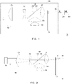
- FIG. 1 is a schematic view of a projection apparatus according to an embodiment not part of the invention.
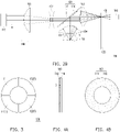
- FIG. 2A and FIG. 2B are diagrams of two optical paths of an illumination system of FIG. 1 in different time periods, wherein FIG. 2A presents a transmission path of an excitation light beam in an illumination light beam outputted from the illumination system, and FIG. 2B presents a transmission path of a converted light beam in the illumination light beam outputted from the illumination system.
- FIG. 3 is a schematic front view of a filter module in FIG. 1 .
- FIG. 4A and FIG. 4B respectively are a schematic side view and a schematic front view of a wavelength conversion module in FIG. 1 .
- a projection apparatus 10 includes an illumination system 100, a light valve 200, and a projection lens 300.
- the illumination system 100 outputs an illumination light beam IB, wherein the illumination light beam IB originates from an excitation light beam B outputted from a filter module 130 in FIG. 2A and a converted light beam CB outputted from the filter module 130 in FIG. 2B .
- the light valve 200 is disposed on a transmission path of the illumination light beam IB and is adapted to convert the illumination light beam IB into an image light beam MB.
- the light valve 200 may be a digital micro-mirror device (DMD), a liquid-crystal-on-silicon panel (LCOS panel), or a transmissive liquid crystal panel, but the invention is not limited thereto.
- the projection lens 300 is disposed on a transmission path of the image light beam MB and projects the image light beam MB onto a screen, a wall, or other objects suitable for imaging.
- the illumination system 100 includes an excitation light source 110, a light combining device 120, a filter module 130, and a wavelength conversion module 140.
- the excitation light source 110 is adapted to provide the excitation light beam B.
- the excitation light source 110 for example, includes one single light emitting device or a plurality of light emitting devices.
- the light emitting device may include a laser diode, a light emitting diode, or a combination of the foregoing two light emitting devices, and the plurality of light emitting devices may include laser diodes and light emitting diodes arranged in an array.
- the light combining device 120 is disposed on a transmission path of the excitation light beam B emitted from the excitation light source 110.
- the light combining device 120 includes a dichroic portion 122 and a reflection portion 124, and the dichroic portion 122 and the reflection portion 124 are disposed on the same device.
- the dichroic portion 122 and the reflection portion 124 are formed on different areas of the same carrier board.
- the dichroic portion 122 and the reflection portion 124 are formed on two physically-separated carrier boards, such that the dichroic portion 122 and the reflection portion 124 are separated from each other.
- the dichroic portion 122 is, for example, a dichroic mirror
- the reflection portion 124 is, for example, a mirror, but the invention is not limited thereto.
- the dichroic portion 122 is disposed on the transmission path of the excitation light beam B emitted from the excitation light source 110, and the dichroic portion 122 allows the excitation light beam B to pass through.
- the dichroic portion 122 is also disposed on a transmission path of the converted light beam CB (referring to the thick solid line) reflected by the wavelength conversion module 140, and the dichroic portion 122 reflects the converted light beam CB.
- the reflection portion 124 is disposed on a transmission path of the excitation light beam B reflected by the filter module 130, and the reflection portion 124 reflects the excitation light beam B to the wavelength conversion module 140.
- the reflection portion 124 is also disposed on the transmission path of the converted light beam CB reflected by the wavelength conversion module 140, and the reflection portion 124 reflects the converted light beam CB to the filter module 130.
- the filter module 130 is disposed on a transmission path of the excitation light beam B transmitted from the light combining device 120.
- the filter module 130 is, for example, a filter wheel.
- the filter module 130 is disposed on a transmission path of the excitation light beam B passing through the dichroic portion 122 of the light combining device 120.
- the filter module 130 includes a light passing-through area T allowing the excitation light beam B to pass through and at least one filter area F reflecting the excitation light beam B.
- a filter area allowing at least a portion of the excitation light beam B to pass through may be disposed in the light passing-through area T.
- the filter module 130 may include three filter areas, such as a first color filter area F1, a second color filter area F2, and a third color filter area F3 as shown in FIG. 3 .
- a first color filter plate allowing a first color light beam to pass through and reflecting light beams of remaining colors (e.g., the excitation light beam B and a second color light beam) is disposed in the first color filter area F1.
- a second color filter plate allowing the second color light beam to pass through and reflecting light beams of the remaining colors (e.g., the excitation light beam B and the first color light beam) is disposed in the second color filter area F2.
- a third color filter plate allowing the converted light beam CB to pass through and reflecting the excitation light beam B is disposed in the third color filter area F3.
- the excitation light beam B is a blue light beam
- the converted light beam CB is a yellow light beam
- the first color light beam and the second color light beam are respectively a red light beam and a green light beam
- the converted light beam CB includes the first color light beam and the second color light beam.
- a blue filter plate, a red filter plate, a green filter plate, and a yellow filter plate are respectively disposed in the light passing-through area T, the first color filter area F1, the second color filter area F2, and the third color filter area F3.
- the number of the at least one filter area F, the color of each of the at least one filter area F, and arrangement of the filter areas F in the filter module 130 can be changed according to actual requirements and are not limited to what is shown in FIG. 3 .
- the filter module 130 may omit the third color filter area F3.
- the filter plate is adapted to filter out a portion of a wavelength in a light beam, so that the light beam passing through the filter plate has the required wavelength , and thus the filter plate has the function of purifying the color of the light beam.
- the at least one filter area F (e.g., the first color filter area F1, the second color filter area F2, or the third color filter area F3) cuts into the transmission path of the excitation light beam B passing through the dichroic portion 122 of the light combining device 120, the at least one filter area F reflects the excitation light beam B.
- the wavelength conversion module 140 is, for example, a phosphor wheel.
- the wavelength conversion module 140 and the filter module 130 are disposed at the same side of the light combining device 120, and the excitation light source 110 and the wavelength conversion module 140 are disposed at opposite sides of the light combining device 120.
- the wavelength conversion module 140 is disposed on a transmission path of the excitation light beam B reflected by the at least one filter area F.
- the reflection portion 124 of the light combining device 120 is disposed on the transmission path of the excitation light beam B reflected by the at least one filter area F
- the wavelength conversion module 140 is disposed on a transmission path of the excitation light beam B reflected by the reflection portion 124 of the light combining device 120.
- the excitation light beam B reflected by the at least one filter area F is transmitted towards the wavelength conversion module 140 through being reflected by the reflection portion 124 of the light combining device 120.
- the wavelength conversion module 140 is adapted to convert the excitation light beam B reflected by the at least one filter area F into the converted light beam CB and reflects the converted light beam CB, as such, the converted light beam CB is transmitted towards the at least one filter area F.
- the wavelength conversion module 140 may include a wavelength conversion layer 142 and a carrier board 144.
- the wavelength conversion layer 142 absorbs a short-wavelength light beam (the excitation light beam B) and is excited to emit a longwavelength light beam (the converted light beam CB).
- the material of the wavelength conversion layer 142 may include phosphors, quantum dots, or a combination of the two materials.
- the material of the wavelength conversion layer 142 may also selectively include lightscattering particles to increase scattering efficiency.
- the carrier board 144 features a reflective characteristic and is adapted to reflect the converted light beam CB back to the light combining device 120.
- the carrier board 144 may be a metal carrier board or a carrier board having high reflection coating. In this way, the carrier board 144 features not only a reflective characteristic but also a heat dissipation characteristic.
- the carrier board 144 may be a light transmissive carrier board, and a reflection layer is formed at least on a surface S of the carrier board 144 facing the wavelength conversion layer 142.
- the wavelength conversion layer 142 is disposed on the surface S of the carrier board 144 facing the light combining device 120.
- the wavelength conversion layer 142 is disposed between the carrier board 144 and the light combining device 120, and the wavelength conversion layer 142 may be disposed along a circumference of the carrier board 144 to form a ring-shaped distribution. Nevertheless, the invention is not intended to limit how the wavelength conversion layer 142 is disposed on the carrier board 144.
- the light passing-through area T and the at least one filter area F of the filter module 130 may alternately cut into the transmission path of the excitation light beam B transmitted from the light combining device 120.
- the light passing-through area T of the filter module 130 cuts into the transmission path of the excitation light beam B transmitted from the dichroic portion 122 of the light combining device 120, as shown in FIG. 2A
- the excitation light beam B passes through the light passing-through area T of the filter module 130 and is outputted from the filter module 130.
- the at least one filter area F of the filter module 130 the first color filter area F1, the second color filter area F2, or the third color filter area F3 as shown in FIG.
- the converted light beam CB passes through the at least one filter area F of the filter module 130 and is outputted from the filter module 130.
- the at least one filter area F reflects the excitation light beam B passing through the dichroic portion 122 of the light combining device 120.
- the reflection portion 124 of the light combining device 120 is disposed on the transmission path of the excitation light beam B reflected by the at least one filter area F of the filter module 130, as such, the excitation light beam B passing through the dichroic portion 122 is reflected by the at least one filter area F and the reflection portion 124 in sequence and is transmitted to the wavelength conversion module 140.
- the wavelength conversion module 140 converts the excitation light beam B into the converted light beam CB, and the converted light beam CB reflected by the wavelength conversion module 140 is transmitted to the filter module 130 through being reflected by the dichroic portion 122 and the reflection portion 124.
- the excitation light beam B passing through the light passing-through area T in FIG. 2A and the converted light beam CB passing through the at least one filter area F in FIG. 2B form the illumination light beam IB in FIG. 1 .
- FIG. 2B presents the optical path when the third color filter area F3 (the yellow filter area) of FIG. 3 cuts into the transmission path of the excitation light beam B passing through the dichroic portion 122 of the light combining device 120.
- the third color filter area F3 cuts into the transmission path of the excitation light beam B passing through the dichroic portion 122 of the light combining device 120
- at least a portion of the (or the entire) converted light beam CB (the yellow light beam) transmitted to the filter module 130 continues to pass through the third color filter area F3 and is outputted from the filter module 130.
- the first color light beam (the red light beam) in the converted light beam CB (the yellow light beam) transmitted to the filter module 130 continues to pass through the first color filter area F1 and is outputted from the filter module 130, and the second color light beam (the green light beam) in the converted light beam CB (the yellow light beam) transmitted to the filter module 130 is filtered (reflected or absorbed) by the first color filter area F1.
- the second color light beam (the green light beam) in the converted light beam CB (the yellow light beam) transmitted to the filter module 130 continues to pass through the second color filter area F2 and is outputted from the filter module 130, and the first color light beam (the red light beam) in the converted light beam CB (the yellow light beam) transmitted to the filter module 130 is filtered (reflected or absorbed) by the second color filter area F2.
- the excitation light beam B emitted from the excitation light source 110 may be transmitted to the filter module 130 first through the light combining device 120 without being transmitted to the wavelength conversion module 140, and the excitation light beam B transmitted to the filter module 130 is outputted from the filter module 130 through the light passing-through area T of the filter module 130.
- an opening allowing the excitation light beam B to pass through is not required to be formed in the wavelength conversion module 140 (e.g., in the carrier board 144), and a plurality of light transmission devices configured for transmitting the excitation light beam B passing through the opening back to the light combining device 120 are not required to be additionally disposed either.
- the illumination system 100 may feature advantages such as lowered costs and reduced volume.
- the wavelength conversion module 140 converts the blue excitation light beam B into the yellow converted light beam CB, and the yellow converted light beam CB is then filtered through the plurality of filter areas F of the filter module 130 to produce light beams of a variety of colors (e.g., red light, green light, or yellow light) required for illumination. That is, in the wavelength conversion module 140, only an optical wavelength conversion material configured for converting the yellow light is required to be disposed on the carrier board 144, and the wavelength conversion module 140 is not required to be divided into a light passing-through area and a plurality of wavelength conversion areas with different optical wavelength conversion materials being disposed in corresponding to the light passing-through area T and the plural filter areas F of the filter module 130.
- a variety of colors e.g., red light, green light, or yellow light
- rotation of the filter module 130 may not be synchronized with rotation of the wavelength conversion module 140.
- the wavelength conversion module 140 may not rotate.
- the wavelength conversion module 140 may rotate but may not have to rotate synchronously with the filter module 130, and the rotation of the filter module 130 and the rotation of the wavelength conversion module 140 are not required to be designed to be synchronous, as such, time for processing electric signals in the projection apparatus 10 is significantly saved.
- the light valve 200 supporting synchronous rotation only with the filter module 130 may be selected for the projection apparatus 10, so as to reduce costs of the projection apparatus 10.
- the projection apparatus 10 applying the illumination system 100 may also feature the advantages such as reduced volume and lowered costs.
- the illumination system 100 may selectively include other devices.
- the illumination system 100 may further include a plurality of lens devices such as a lens device 151, a lens device 152, a lens device 153, a lens device 154, and a lens device 155 as shown in FIG. 1 , so as to converge the light beams or collimate the light beams.
- the illumination system 100 may also include a light uniforming device 160.
- the light uniforming device 160 is disposed on transmission paths of the excitation light beam B and the converted light beam CB outputted from the filter module 130, so as to enhance uniformity of the light beams.
- the light uniforming device 160 is a light integration rod or a lens array, but the invention is not limited thereto.
- FIG. 5 is a schematic diagram of an illumination system according to another embodiment which is part of the invention, and FIG. 5 presents an optical path when the third color filter area F3 (the yellow filter area) of FIG. 3 cuts into the transmission path of the excitation light beam B passing through the dichroic portion 122 of the light combining device 120.
- F3 the yellow filter area
- an illumination system 200 is similar to the illumination system 100 of FIG. 1 , wherein identical devices are denoted by the same reference numerals, and details thereof will not be repeated hereinafter.
- a difference between the illumination system 200 and the illumination system 100 includes the following.
- the dichroic portion 122 and the reflection portion 124 are separated from each other, and the dichroic portion 122 is located between the reflection portion 124 and the wavelength conversion module 140.
- FIG. 2A may be referenced for a light path of the excitation light beam B.
- the at least one filter area F (referring to FIG.
- the filter module 130 cuts into the transmission path of the excitation light beam B passing through the dichroic portion 122 of the light combining device 120, the excitation light beam B passing through the dichroic portion 122 passes through the dichroic portion 122 and is transmitted to the reflection portion 124, is reflected by the reflection portion 124, passes through the dichroic portion 122 again, and is transmitted to the wavelength conversion module 140 in sequence after being reflected by the at least one filter area F.
- the converted light beam CB reflected by the wavelength conversion module 140 is transmitted towards the filter module 130 through being reflected by the dichroic portion 122.
- the dichroic portion 122 reflects the converted light beam CB, and the dichroic portion 122 is located between the reflection portion 124 and the wavelength conversion module 140, the converted light beam CB is reflected by the dichroic portion 122 when being transmitted to the dichroic portion 122. That is, the converted light beam CB is not transmitted to the reflection portion 124 and is not reflected by the reflection portion 124 either.
- the dichroic portion 122 of the light combining device 120 allows the excitation light beam B to pass through and reflects the converted light beam CB.
- the excitation light source 110 is turned on in any time period.
- FIG. 6 is a schematic diagram of an illumination system according a third embodiment not part of the invention.
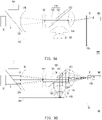
- FIG. 7A to FIG. 7C are views of three optical paths of the illumination system of the third embodiment in different time periods, wherein FIG. 7A presents a transmission path of an excitation light beam in an illumination light beam outputted from the illumination system, FIG. 7B presents a transmission path of a first color light beam in the illumination light beam outputted from the illumination system, and FIG. 7C presents a transmission path of a second color light beam in the illumination light beam outputted from the illumination system.
- the filter module may include or may not include the third color filter area F3 shown in FIG. 3 . Description of the third color filter area F3 has been specified above, and details thereof will not be repeated hereinafter.
- an illumination system 300 is similar to the illumination system 100 of FIG. 1 , wherein identical devices are denoted by the same reference numerals, and details thereof will not be repeated hereinafter.
- a difference between the illumination system 300 and the illumination system 100 includes the following.
- the illumination system 300 further includes a first color supplementary light source 310 and a dichroic device 320.
- the first color supplementary light source 310 provides a first color light beam B1 (the red light beam).
- the dichroic device 320 for example, is a dichroic mirror.
- the dichroic device 320 is disposed on the transmission path of the excitation light beam B emitted from the excitation light source 110 and on a transmission path of the first color light beam B1 emitted from the first color supplementary light source 310.
- the excitation light beam B emitted from the excitation light source 110 and the first color light beam B1 emitted from the first color supplementary light source 310 are transmitted to the light combining device 120 through the dichroic device 320.
- the dichroic device 320 allows the excitation light beam B to pass through and reflects the first color light beam B1, but the invention is not limited thereto.
- the dichroic device 320 may allow the first color light beam B1 to pass through and reflects the excitation light beam B.
- the first color supplementary light source 310 is adapted to increase a red light component in the illumination light beam, so as to improve the problem of impurity of the red light color in the prior art.
- the first color supplementary light source 310 is, for example, a red laser diode or a red light emitting diode.
- the first color filter area F1 shown in FIG. 3 cuts into a transmission path of the first color light beam B1 transmitted from the light combining device 120.
- the first color supplementary light source 310 is turned off when the light passing-through area T or the second color filter area F2 cuts into the transmission path of the excitation light beam B transmitted from the light combining device 120.
- the first color supplementary light source 310 is turned on only when the first color filter area F1 cuts into the transmission path of the first color light beam B1 transmitted from the light combining device 120 and is turned off in the rest of the time periods.
- the excitation light source 110 may be turned on in any time period.
- the excitation light source 110 may be turned off when the first color supplementary light source 310 is turned on, and the excitation light source 110 may be turned on when the first color supplementary light source 310 is turned off. Description is provided in detail as follows.
- the dichroic portion 122 is disposed on transmission paths of the excitation light beam B and the first color light beam B1 transmitted from the dichroic device 320.
- the dichroic portion 122 allows the excitation light beam B and the first color light beam B1 transmitted from the dichroic device 320 to pass through and reflects light beams of the remaining colors (e.g., the second color light beam).
- the first color filter area F1 of the filter module 130 (referring to FIG. 3 ) allows at least a portion of the first color light beam B1 to pass through and reflects light beams of the remaining colors.
- the reflection portion 124 is disposed on a transmission path of the excitation light beam B reflected by the first color filter area F1 or the second color filter area F2 and reflects the excitation light beam B.
- the first color supplementary light source 310 is turned off, and the excitation light beam B emitted from the excitation light source 110 passes through the dichroic device 320, the lens device 151, the lens device 152, the dichroic portion 122, the lens device 153, and the light passing-through area T of the filter module 130 in sequence and is outputted from the filter module 130.
- the first color filter area F1 of the filter module 130 cuts into the transmission path of the first color light beam B1 transmitted from the light combining device 120
- the first color light beam B1 emitted from the first color supplementary light source 310 passes through the lens device 151, the lens device 152, the dichroic portion 122, the lens device 153, and the first color filter area F1 of the filter module 130 in sequence and is outputted from the filter module 130 after being reflected by the dichroic device 320.
- the excitation light source 110 may be turned on.
- the excitation light beam B emitted from the excitation light source 110 passes through the dichroic device 320, the lens device 151, the lens device, 152, the dichroic portion 122, and the lens device 153 in sequence and then is reflected by the first color filter area F1 of the filter module 130.
- the reflected excitation light beam B then passes through the lens device 153, is reflected by the reflection portion 124, passes through the lens device 154 and the lens device 155, is transmitted to the wavelength conversion module 140, and is converted into the converted light beam CB.
- the converted light beam CB is reflected by the wavelength conversion module 140, passes through the lens device 155 and the lens device 154 in sequence, and is then transmitted to dichroic portion 122 and the reflection portion 124.
- the dichroic portion 122 allows a first color light beam CB1 in the converted light beam CB to pass through and reflects a second color light beam CB2 in the converted light beam CB.
- the reflection portion 124 reflects the first color light beam CB1 and the second color light beam CB2 in the converted light beam CB.
- the first color filter area F1 of the filter module 130 allows the first color light beam CB1 in the converted light beam CB to pass through and filters (reflects/absorbs) the second color light beam CB2 in the converted light beam CB.
- the light beams passing through the first color filter area F1 include the first color light beam B1 emitted from the first color supplementary light source 310 and the first color light beam CB1 in the converted light beam CB.
- the excitation light source 110 may be turned off as well. In this way, the light beam passing through the first color filter area F1 includes only the first color light beam B1 emitted from the first color supplementary light source 310 and does not include the first color light beam CB1 in the converted light beam CB.
- the second color filter area F2 of the filter module 130 allows at least a portion of the second color light beam CB2 in the converted light beam CB to pass through and filters (reflects/absorbs) light beams of the remaining colors (e.g., reflects the first color light beam CB1 in the converted light beam CB).
- the light beam passing through the second color filter area F2 is the second color light beam CB2 in the converted light beam CB.
- FIG. 8 is a schematic diagram of an illumination system according a fourth embodiment which is part of the invention.
- FIG. 9A to FIG. 9C are diagrams of three optical paths of the illumination system of the fourth embodiment of the invention in different time periods, wherein FIG. 9A presents a transmission path of an excitation light beam in an illumination light beam outputted from the illumination system, FIG. 9B presents a transmission path of a first color light beam in the illumination light beam outputted from the illumination system, and FIG. 9C presents a transmission path of a second color light beam in the illumination light beam outputted from the illumination system.
- the filter module may include or may not include the third color filter area F3 shown in FIG. 3 . Description of the third color filter area F3 has been specified above, and details thereof will not be repeated hereinafter.
- an illumination system 400 is similar to the illumination system 300 of FIG. 6 , wherein identical devices are denoted by the same reference numerals, and details thereof will not be repeated hereinafter.
- a difference between the illumination system 400 and the illumination system 300 includes the following.
- the dichroic portion 122 and the reflection portion 124 are separated from each other, and the dichroic portion 122 is located between the reflection portion 124 and the wavelength conversion module 140.
- the transmission path of the excitation light beam B is identical to that shown in FIG. 7A , and thus no further description is provided herein.
- the transmission path of the first color light beam B1 transmitted from the first color supplementary light source 310 is identical to that shown in FIG. 7B , and thus no further description is provided herein.
- the excitation light source 110 is turned on and the first color supplementary light source 310 is turned on.
- the transmission paths of the excitation light beam B and the converted light beam CB are approximately similar to the transmission paths of the excitation light beam B and the converted light beam CB in FIG. 7B , and a difference therebetween is described as follows.
- the excitation light beam B reflected by the first color filter area F1 of the filter module 130 passes through the lens device 153 and the dichroic portion 122 in sequence, is reflected by the reflection portion 124, passes through the dichroic portion 122 again, passes through the lens device 154 and the lens device 155, and is then transmitted to the wavelength conversion module 140 and converted into the converted light beam CB.
- the converted light beam CB is reflected by the wavelength conversion module 140, passes through the lens device 155 and the lens device 154 in sequence, and is then transmitted to dichroic portion 122.
- the dichroic portion 122 allows a first color light beam CB1 in the converted light beam CB to pass through and reflects a second color light beam CB2 in the converted light beam CB.
- At least a portion of the first color light beam CB1 passing through the dichroic portion 122 passes through the dichroic portion 122 again through being reflected by the reflection portion 124 and is transmitted towards the first color filter area F1 of the filter module 130.
- the first color filter area F1 of the filter module 130 allows the first color light beam B1 of the first color supplementary light source 310 and the first color light beam CB1 in the converted light beam CB to pass through and reflects the second color light beam CB2 in the converted light beam CB.
- the second color filter area F2 of the filter module 130 allows at least a portion of the second color light beam CB2 in the converted light beam CB to pass through and filters (reflects/absorbs) light beams of the remaining colors (e.g., reflects the first color light beam CB1 in the converted light beam CB).
- the dichroic portion 122 of the light combining device 120 allows the excitation light beam B, the first color light beam B1, and the first color light beam B1 in the converted light beam CB to pass through and reflects the second color light beam CB2.
- FIG. 10 is a schematic diagram of an illumination system according a fifth embodiment not part of the invention.
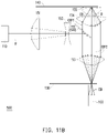
- FIG. 11A and FIG. 11B are diagrams of two optical paths of the illumination system of the fifth embodiment in different time periods, wherein FIG. 11A presents a transmission path of an excitation light beam in an illumination light beam outputted from the illumination system, and FIG. 11B presents a transmission path of a converted light beam in the illumination light beam outputted from the illumination system. Further, FIG. 11B presents the optical path when the third color filter area F3 (the yellow filter area) of FIG. 3 cuts into the transmission path of the excitation light beam B passing through the dichroic portion 122 of the light combining device 120.
- the third color filter area F3 the yellow filter area
- an illumination system 500 is similar to the illumination system 100 of FIG. 1 , wherein identical devices are denoted by the same reference numerals, and details thereof will not be repeated hereinafter.
- a difference between the illumination system 500 and the illumination system 100 includes the following.
- a light combining device 520 includes a dichroic portion 522 but does not include the reflection portion 124 of FIG. 1 .
- the dichroic portion 522 reflects the excitation light beam B and allows the converted light beam CB to pass through.
- the dichroic portion 522 is disposed on the transmission path of the excitation light beam B emitted from the excitation light source 110 and on a transmission path of a first portion CBP1 of the converted light beam CB reflected by the wavelength conversion module 140. Moreover, the dichroic portion 522 is disposed outside a transmission path of a second portion CBP2 of the converted light beam CB reflected by the wavelength conversion module 140. In other words, before the converted light beam CB is transmitted to the filter module 130, only the first portion CBP1 of the converted light beam CB passes through the dichroic portion 522, and the second portion CBP2 of the converted light beam CB does not pass through the dichroic portion 522.
- the excitation light beam B emitted from the excitation light source 110 passes through the lens device 151 and the lens device 152 in sequence, is reflected by the dichroic portion 522, passes through the lens device 153 and the light passing-through area T of the filter module 130 in sequence, and is outputted from the filter module 130.
- the excitation light beam B emitted from the excitation light source 110 passes through the lens device 151 and the lens device 152 in sequence, is reflected by the dichroic portion 522, passes through the lens device 153, and is then reflected by the at least one filter area F of the filter module 130.
- the excitation light beam B reflected by the at least one filter area F passes through the lens device 153, the lens device 154, and the lens device 155 in sequence and is then transmitted to the wavelength conversion module 140 and converted into the converted light beam CB.
- the converted light beam CB is reflected by the wavelength conversion module 140 and passes through the lens device 155 and the lens device 154 in sequence. After passing through the lens device 154, the first portion CBP1 of the converted light beam CB passes through the dichroic portion 522, the lens device 153, and the at least one filter area F of the filter module 130 in sequence and is outputted from the filter module 130. In addition, the second portion CBP2 of the converted light beam CB passes through the lens device 153 and the at least one filter area F of the filter module 130 in sequence and is outputted from the filter module 130.
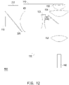
- FIG. 12 is a schematic diagram of an illumination system according a sixth embodiment not part of the invention.
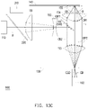
- FIG. 13A to FIG. 13C are diagrams of three optical paths of the illumination system of the sixth embodiment in different time periods, wherein FIG. 13A presents a transmission path of an excitation light beam in an illumination light beam outputted from the illumination system, FIG. 13B presents a transmission path of a first color light beam in the illumination light beam outputted from the illumination system, and FIG. 13C presents a transmission path of a second color light beam in the illumination light beam outputted from the illumination system.
- the filter module may include or may not include the third color filter area F3 shown in FIG. 3 . Description of the third color filter area F3 has been specified above, and details thereof will not be repeated hereinafter.
- an illumination system 600 is similar to the illumination system 500 of FIG. 10 , wherein identical devices are denoted by the same reference numerals, and details thereof will not be repeated hereinafter.
- a difference between the illumination system 600 and the illumination system 500 includes the following.
- the illumination system 600 further includes the first color supplementary light source 310 and the dichroic device 320. Description of the first color supplementary light source 310 and the dichroic device 320 has been specified above, and details thereof will not be repeated hereinafter.
- the dichroic portion 522 of the light combining device 520 is also adapted to reflect the first color light beam B1 of the first color supplementary light source 310.
- the transmission path of the excitation light beam B is identical to that shown in FIG. 11A , and thus no further description is provided herein.
- the first color filter area F1 of the filter module 130 cuts into a transmission path of the first color light beam B1 transmitted from dichroic portion 522 of the light combining device 520
- the first color light beam B1 emitted from the first color supplementary light source 310 passes through the lens device 151 and the lens device 152 in sequence, is reflected by the dichroic portion 522, passes through the lens device 153 and the first color filter area F1 of the filter module 130 in sequence, and is outputted from the filter module 130 after being reflected by the dichroic device 320.
- the excitation light source 110 may be turned on as well.
- the excitation light beam B emitted from the excitation light source 110 passes through the dichroic device 320, the lens device 151, and the lens device 152 in sequence, is reflected by the dichroic portion 522, passes through the lens device 153, and then is reflected by the first color filter area F1 of the filter module 130.
- the reflected excitation light beam B then passes through the lens device 153, the lens device 154, and the lens device 155 in sequence and is transmitted to the wavelength conversion module 140 and converted into the converted light beam CB.
- the converted light beam CB is reflected by the wavelength conversion module 140 and passes through the lens device 155 and the lens device 154 in sequence.
- the dichroic portion 522 is disposed on the transmission path of the first portion CBP1 of the converted light beam CB reflected by the wavelength conversion module 140. Moreover, the dichroic portion 522 is disposed outside the transmission path of the second portion CBP2 of the converted light beam CB reflected by the wavelength conversion module 140.
- the dichroic portion 522 allows the second color light beam CB2 in the converted light beam CB to pass through and reflects the first color light beam CB1 in the converted light beam CB.
- the second color light beam CB2 passing through the dichroic portion 522 passes through the lens device 153 and then is transmitted to the filter module 130.
- the first color filter area F1 of the filter module 130 allows the first color light beam CB1 in the converted light beam CB to pass through and reflects the second color light beam CB2 in the converted light beam CB.
- the light beams passing through the first color filter area F1 include the first color light beam B1 emitted from the first color supplementary light source 310 and the first color light beam CB1 in the converted light beam CB.
- the excitation light source 110 may be turned off as well. In this way, the light beam passing through the first color filter area F1 includes only the first color light beam B1 emitted from the first color supplementary light source 310 and does not include the first color light beam CB1 in the converted light beam CB.
- the second color filter area F2 of the filter module 130 cuts into the transmission path of the excitation light beam B transmitted from the dichroic portion 522 of the light combining device 520, the first color supplementary light source 310 is turned off.
- the transmission paths of the excitation light beam B and the converted light beam CB are identical to that described in FIG. 13B , and thus no further description is provided herein.
- a difference between FIG. 13C and FIG. 13B is that in FIG. 13C , the second color filter area F2 of the filter module 130 (referring to FIG.
- the second color filter area F2 of the filter module 130 allows the second color light beam CB2 in the converted light beam CB to pass through and reflects the first color light beam CB 1 in the converted light beam CB.
- the light beam passing through the second color filter area F2 is the second color light beam CB2 in the converted light beam CB.
- the dichroic portion 522 of the light combining device 520 reflects the excitation light beam B, the first color light beam B1, and the first color light beam CB1 in the converted light beam CB and allows the second color light beam CB2 to pass through.
- the embodiments of the invention have at least one of the following advantages or effects.
- the light combining device is disposed on the transmission path of the excitation light beam emitted from the excitation light source
- the filter module is disposed on the transmission path of the excitation light beam transmitted from the light combining device. Accordingly, the excitation light beam emitted from the excitation light source may be transmitted to the filter module through the light combining device without being transmitted to the wavelength conversion module, and the excitation light beam transmitted to the filter module is outputted from the filter module through the light passing-through area of the filter module.
- an opening allowing the excitation light beam to pass through is not required to be formed in the wavelength conversion module, and a plurality of light transmission devices configured for transmitting the excitation light beam passing through the opening back to the light combining device are not required to be additionally disposed either.
- the wavelength conversion module is not required to synchronously rotate with the filter module. That is, the light valve supporting synchronous rotation only with the filter module may be selected for the projection apparatus to reduce costs. Therefore, time for processing the electric signals can be saved in the illumination system and the projection apparatus provided by the invention, and thereby, costs are lowered and reduced volume is provided.
Landscapes
- Physics & Mathematics (AREA)
- General Physics & Mathematics (AREA)
- Optics & Photonics (AREA)
- Engineering & Computer Science (AREA)
- Multimedia (AREA)
- Projection Apparatus (AREA)
- Non-Portable Lighting Devices Or Systems Thereof (AREA)
Claims (8)
- Beleuchtungssystem, das Folgendes umfasst:eine Erregungslichtquelle (110), die ausgelegt ist, einen Erregungslichtstrahl (B) bereitzustellen;eine Lichtkombinierungseinrichtung (120), die auf einem Übertragungsweg des Erregungslichtstrahls (B), der von der Erregungslichtquelle emittiert wird, angeordnet ist;ein Filtermodul (130), das auf einem Übertragungsweg des Erregungslichtstrahls (B), der von der Lichtkombinierungseinrichtung (120) emittiert wird, angeordnet ist, wobei das Filtermodul (130) einen Lichtdurchlassbereich, der ermöglicht, dass der Erregungslichtstrahl (B) hindurch verläuft, und mindestens einen Filterbereich (F), der den Erregungslichtstrahl (B) reflektiert, umfasst; undein Wellenlängen-Umsetzungsmodul (140), das auf einem Übertragungsweg des Erregungslichtstrahls (B), der durch den mindestens einen Filterbereich (F) reflektiert wird, angeordnet ist, wobei das Wellenlängen-Umsetzungsmodul (140) ausgelegt ist, den Erregungslichtstrahl (B), der durch den mindestens einen Filterbereich (F) reflektiert wird, in einen umgesetzten Lichtstrahl (CB) umzusetzen und den umgesetzten Lichtstrahl (CB) zu reflektieren, derart, dass der umgesetzte Lichtstrahl (CB) in Richtung des mindestens einen Filterbereichs (F) übertragen wird, und der Erregungslichtstrahl (B), der durch den Lichtdurchlassbereich verläuft, und der umgesetzte Lichtstrahl (CB), der durch den mindestens einen Filterbereich (F) verläuft, einen Beleuchtungslichtstrahl bilden;dadurch gekennzeichnet, dass die Lichtkombinierungseinrichtung (120) einen dichroitischen Abschnitt (122) und einen Reflexionsabschnitt (124) umfasst, wobei der dichroitische Abschnitt (122) und der Reflexionsabschnitt (124) auf zwei physikalisch getrennten Trägerplatten gebildet sind, derart, dass der dichroitische Abschnitt (122) und der Reflexionsabschnitt (124) voneinander getrennt sind.
- Beleuchtungssystem nach Anspruch 1, wobei der dichroitische Abschnitt (122) ermöglicht, dass der Erregungslichtstrahl (B) hindurch verläuft, der Reflexionsabschnitt (124) den Erregungslichtstrahl (B) reflektiert, der dichroitische Abschnitt (122) auf dem Übertragungsweg des Erregungslichtstrahls (B), der von der Erregungslichtquelle (110) emittiert wird, und auf einem Übertragungsweg des umgesetzten Lichtstrahls (CB), der durch das Wellenlängen-Umsetzungsmodul (140) reflektiert wird, angeordnet ist und der Reflexionsabschnitt (124) auf dem Übertragungsweg des Erregungslichtstrahls (B), der durch den mindestens einen Filterbereich (F) reflektiert wird, angeordnet ist.
- Beleuchtungssystem nach Anspruch 1, wobei der dichroitische Abschnitt (122) zwischen dem Reflexionsabschnitt (124) und dem Wellenlängen-Umsetzungsmodul (140) angeordnet ist, wobei der Erregungslichtstrahl (B) durch den dichroitischen Abschnitt (122) verläuft, durch den Reflexionsabschnitt (124) reflektiert wird, erneut durch den dichroitischen Abschnitt (122) verläuft und in der Folge, nachdem er durch den mindestens einen Filterbereich (F) reflektiert worden ist, zum Wellenlängen-Umsetzungsmodul (140) übertragen wird und der umgesetzte Lichtstrahl (CB), der durch das Wellenlängen-Umsetzungsmodul (140) reflektiert wird, in Richtung des Filtermoduls (130) übertragen wird, indem er durch den dichroitischen Abschnitt (122) reflektiert wird.
- Beleuchtungssystem nach Anspruch 1, wobei der mindestens eine Filterbereich (F) einen ersten Farbfilterbereich (F1) und einen zweiten Farbfilterbereich (F2) umfasst, wobei das Beleuchtungssystem (100, 300) ferner eine erste Zusatzfarblichtquelle (310) und eine dichroitische Einrichtung (320) umfasst.
- Beleuchtungssystem nach Anspruch 4, wobei die erste Zusatzfarblichtquelle (310) einen ersten Farblichtstrahl bereitstellt; unddie dichroitische Einrichtung (320) auf dem Übertragungsweg des Erregungslichtstrahls (B), der von der Erregungslichtquelle (110) emittiert wird, und auf einem Übertragungsweg des ersten Farblichtstrahls, der von der ersten Zusatzfarblichtquelle (310) emittiert wird, angeordnet ist und der Erregungslichtstrahl (B), der von der Erregungslichtquelle (110) emittiert wird, und der erste Farblichtstrahl, der von der ersten Zusatzfarblichtquelle (310) emittiert wird, durch die dichroitische Einrichtung (320) zur Lichtkombinierungseinrichtung (120) übertragen werden,wobei der erste Farbfilterbereich (F1) in einen Übertragungsweg des ersten Farblichtstrahls, der von der Lichtkombinierungseinrichtung (120) übertragen wird, schneidet, wenn die erste Zusatzfarblichtquelle (310) den ersten Farblichtstrahl bereitstellt, und die erste Zusatzfarblichtquelle (310) ausgeschaltet wird, wenn der Lichtdurchlassbereich oder der zweite Farbfilterbereich (F2) in den Übertragungsweg des Erregungslichtstrahls (B), der von der Lichtkombinierungseinrichtung (120) übertragen wird, schneiden,wobei der dichroitische Abschnitt (122) auf den Übertragungswegen des Erregungslichtstrahls (B) und des ersten Farblichtstrahls, die von der dichroitischen Einrichtung (320) übertragen werden, angeordnet ist, der dichroitische Abschnitt (122) ermöglicht, dass der Erregungslichtstrahl (B) und der erste Farblichtstrahl, die von der dichroitischen Einrichtung (320) übertragen werden, hindurch verlaufen, der erste Farbfilterbereich (F1) des Filtermoduls (130) ermöglicht, dass zumindest ein Anteil des ersten Farblichtstrahls hindurch verläuft, und Lichtstrahlen der restlichen Farben reflektiert und der Reflexionsabschnitt (124) auf einem Übertragungsweg des Erregungslichtstrahls (B), der durch den ersten Farbfilterbereich (F1) oder den zweiten Farbfilterbereich (F2) reflektiert wird, angeordnet ist und den Erregungslichtstrahl (B) reflektiert.
- Beleuchtungssystem nach Anspruch 5, wobei der dichroitische Abschnitt (122) zwischen dem Reflexionsabschnitt (124) und dem Wellenlängen-Umsetzungsmodul (140) angeordnet ist, wobei der Erregungslichtstrahl (B) durch den dichroitischen Abschnitt (122) verläuft, durch den Reflexionsabschnitt (124) reflektiert wird, erneut durch den dichroitischen Abschnitt (122) verläuft und in der Folge, nachdem er durch den ersten Farbfilterbereich (F1) oder den zweiten Farbfilterbereich (F2) reflektiert worden ist, zum Wellenlängen-Umsetzungsmodul (140) übertragen wird, der umgesetzte Lichtstrahl (CB) durch das Wellenlängen-Umsetzungsmodul (140) zum dichroitischen Abschnitt (122) reflektiert wird, der dichroitische Abschnitt (122) ermöglicht, dass ein erster Farblichtstrahl im umgesetzten Lichtstrahl (CB) hindurch verläuft, und einen zweiten Farblichtstrahl im umgesetzten Lichtstrahl (CB) reflektiert und zumindest ein Anteil des ersten Farblichtstrahls, der durch den dichroitischen Abschnitt (122) verläuft, durch den Reflexionsabschnitt (124) reflektiert wird, derart, dass er erneut durch den dichroitischen Abschnitt (122) verläuft und in Richtung des Filtermoduls (130) übertragen wird.
- Beleuchtungssystem nach einem der vorhergehenden Ansprüche, wobei eine Drehung des Filtermoduls (130) nicht mit einer Drehung des Wellenlängen-Umsetzungsmoduls (140) synchronisiert ist.
- Projektionsvorrichtung, die Folgendes umfasst:
ein Beleuchtungssystem (100, 300) nach einem der vorhergehenden Ansprüche, das ferner Folgendes umfasst:ein Lichtventil (200), das auf einem Übertragungsweg des Beleuchtungslichtstrahls angeordnet ist und den Beleuchtungslichtstrahl in einen Bildlichtstrahl umsetzt; undeine Projektionslinse (300), die auf einem Übertragungsweg des Bildlichtstrahls angeordnet ist.
Applications Claiming Priority (1)
| Application Number | Priority Date | Filing Date | Title |
|---|---|---|---|
| CN201810542201.2A CN110554554B (zh) | 2018-05-30 | 2018-05-30 | 照明系统以及投影装置 |
Publications (2)
| Publication Number | Publication Date |
|---|---|
| EP3575869A1 EP3575869A1 (de) | 2019-12-04 |
| EP3575869B1 true EP3575869B1 (de) | 2022-08-31 |
Family
ID=66676221
Family Applications (1)
| Application Number | Title | Priority Date | Filing Date |
|---|---|---|---|
| EP19176788.8A Active EP3575869B1 (de) | 2018-05-30 | 2019-05-27 | Beleuchtungssystem und projektionsvorrichtung |
Country Status (3)
| Country | Link |
|---|---|
| US (1) | US10976652B2 (de) |
| EP (1) | EP3575869B1 (de) |
| CN (1) | CN110554554B (de) |
Families Citing this family (7)
| Publication number | Priority date | Publication date | Assignee | Title |
|---|---|---|---|---|
| US11336873B2 (en) * | 2019-07-30 | 2022-05-17 | Coretronic Corporation | Illumination system and projection apparatus |
| CN211826877U (zh) * | 2020-02-10 | 2020-10-30 | 中强光电股份有限公司 | 照明系统及投影装置 |
| CN113934091B (zh) * | 2020-06-29 | 2023-12-01 | 中强光电股份有限公司 | 照明系统与投影装置 |
| CN114137788A (zh) | 2020-09-04 | 2022-03-04 | 中强光电股份有限公司 | 照明系统与投影装置 |
| CN114280880A (zh) | 2020-09-28 | 2022-04-05 | 中强光电股份有限公司 | 照明系统及投影装置 |
| CN213023918U (zh) | 2020-10-26 | 2021-04-20 | 中强光电股份有限公司 | 照明系统以及投影装置 |
| CN213457631U (zh) * | 2020-11-30 | 2021-06-15 | 中强光电股份有限公司 | 照明系统及投影装置 |
Family Cites Families (15)
| Publication number | Priority date | Publication date | Assignee | Title |
|---|---|---|---|---|
| CN104965385B (zh) * | 2011-07-08 | 2018-01-26 | 深圳市光峰光电技术有限公司 | 投影系统、光源系统以及光源组件 |
| CN103207507B (zh) | 2012-01-11 | 2015-07-08 | 中强光电股份有限公司 | 光源模组与投影装置 |
| JP2014075221A (ja) * | 2012-10-03 | 2014-04-24 | Mitsubishi Electric Corp | 光源装置 |
| TWI461740B (zh) * | 2012-10-31 | 2014-11-21 | Delta Electronics Inc | 立體顯示固態光源模組 |
| JP6292523B2 (ja) * | 2013-01-10 | 2018-03-14 | Zero Lab株式会社 | 波長変換デバイス、照明光学系およびこれを用いた電子装置 |
| TWI504832B (zh) * | 2014-05-02 | 2015-10-21 | Coretronic Corp | 照明系統及投影裝置 |
| TWI522723B (zh) | 2014-05-26 | 2016-02-21 | 台達電子工業股份有限公司 | 光源系統及其適用之投影設備 |
| CN105204278B (zh) * | 2014-05-26 | 2017-05-10 | 台达电子工业股份有限公司 | 光源系统及其适用的投影设备 |
| TWI503578B (zh) | 2014-06-13 | 2015-10-11 | Coretronic Corp | 光源模組與投影裝置 |
| KR20160019177A (ko) | 2014-08-11 | 2016-02-19 | 엘지전자 주식회사 | 일체형 파장 변환 휠 및 컬러 휠이 구비된 프로젝션 장치 |
| DE102014222130A1 (de) * | 2014-10-29 | 2016-05-04 | Osram Gmbh | Beleuchtungsvorrichtung mit einer Wellenlängenkonversionsanordnung |
| JP6967689B2 (ja) * | 2016-03-15 | 2021-11-17 | パナソニックIpマネジメント株式会社 | 光源装置及び投写型映像表示装置 |
| US20190004409A1 (en) * | 2017-06-30 | 2019-01-03 | Panasonic Intellectual Property Management Co., Ltd. | Light source apparatus and projection display apparatus |
| US11067880B2 (en) * | 2017-10-03 | 2021-07-20 | Casio Computer Co., Ltd | Light source unit and projector |
| CN208547803U (zh) * | 2018-05-30 | 2019-02-26 | 中强光电股份有限公司 | 照明系统以及投影装置 |
-
2018
- 2018-05-30 CN CN201810542201.2A patent/CN110554554B/zh active Active
-
2019
- 2019-05-23 US US16/421,411 patent/US10976652B2/en active Active
- 2019-05-27 EP EP19176788.8A patent/EP3575869B1/de active Active
Also Published As
| Publication number | Publication date |
|---|---|
| US10976652B2 (en) | 2021-04-13 |
| CN110554554A (zh) | 2019-12-10 |
| US20190369470A1 (en) | 2019-12-05 |
| EP3575869A1 (de) | 2019-12-04 |
| CN110554554B (zh) | 2022-04-12 |
Similar Documents
| Publication | Publication Date | Title |
|---|---|---|
| US10976652B2 (en) | Illumination system and projection apparatus | |
| CN104516180B (zh) | 光波长转换模块、照明系统以及投影装置 | |
| US9152031B2 (en) | Light source module and projection apparatus | |
| US9977317B2 (en) | Illumination system and projection device | |
| US9341933B2 (en) | Wavelength conversion and filtering module and light source system | |
| CN110161791B (zh) | 照明系统及投影装置 | |
| US10368043B2 (en) | Projector and illumination system thereof | |
| EP3514622B1 (de) | Beleuchtungssystem und projektionsvorrichtung | |
| US10948811B2 (en) | Illumination system and projection apparatus | |
| US20200004120A1 (en) | Illumination system and projection apparatus | |
| US9977316B2 (en) | Projection apparatus and illumination system thereof | |
| US10802387B2 (en) | Illumination system, projection apparatus, and projection method of projection apparatus | |
| US20170163947A1 (en) | Projector and wavelength conversion device | |
| US20150323156A1 (en) | Light source device | |
| US10921696B2 (en) | Illumination system and projection apparatus | |
| US11852962B2 (en) | Light source module and projection device | |
| EP3989000B1 (de) | Projektionsvorrichtung und beleuchtungssystem | |
| US11086206B2 (en) | Illumination system, projection apparatus, and projection method of projection apparatus | |
| US10928719B2 (en) | Projector and illumination system | |
| US11709353B2 (en) | Illumination system and projection device | |
| US10816885B2 (en) | Illumination system, projection apparatus, and projection method of projection apparatus |
Legal Events
| Date | Code | Title | Description |
|---|---|---|---|
| PUAI | Public reference made under article 153(3) epc to a published international application that has entered the european phase |
Free format text: ORIGINAL CODE: 0009012 |
|
| STAA | Information on the status of an ep patent application or granted ep patent |
Free format text: STATUS: THE APPLICATION HAS BEEN PUBLISHED |
|
| AK | Designated contracting states |
Kind code of ref document: A1 Designated state(s): AL AT BE BG CH CY CZ DE DK EE ES FI FR GB GR HR HU IE IS IT LI LT LU LV MC MK MT NL NO PL PT RO RS SE SI SK SM TR |
|
| AX | Request for extension of the european patent |
Extension state: BA ME |
|
| STAA | Information on the status of an ep patent application or granted ep patent |
Free format text: STATUS: REQUEST FOR EXAMINATION WAS MADE |
|
| 17P | Request for examination filed |
Effective date: 20200526 |
|
| RBV | Designated contracting states (corrected) |
Designated state(s): AL AT BE BG CH CY CZ DE DK EE ES FI FR GB GR HR HU IE IS IT LI LT LU LV MC MK MT NL NO PL PT RO RS SE SI SK SM TR |
|
| RIC1 | Information provided on ipc code assigned before grant |
Ipc: G03B 33/08 20060101ALI20211203BHEP Ipc: G03B 21/20 20060101AFI20211203BHEP |
|
| GRAP | Despatch of communication of intention to grant a patent |
Free format text: ORIGINAL CODE: EPIDOSNIGR1 |
|
| STAA | Information on the status of an ep patent application or granted ep patent |
Free format text: STATUS: GRANT OF PATENT IS INTENDED |
|
| INTG | Intention to grant announced |
Effective date: 20220120 |
|
| GRAJ | Information related to disapproval of communication of intention to grant by the applicant or resumption of examination proceedings by the epo deleted |
Free format text: ORIGINAL CODE: EPIDOSDIGR1 |
|
| STAA | Information on the status of an ep patent application or granted ep patent |
Free format text: STATUS: REQUEST FOR EXAMINATION WAS MADE |
|
| GRAP | Despatch of communication of intention to grant a patent |
Free format text: ORIGINAL CODE: EPIDOSNIGR1 |
|
| STAA | Information on the status of an ep patent application or granted ep patent |
Free format text: STATUS: GRANT OF PATENT IS INTENDED |
|
| INTC | Intention to grant announced (deleted) | ||
| INTG | Intention to grant announced |
Effective date: 20220412 |
|
| GRAS | Grant fee paid |
Free format text: ORIGINAL CODE: EPIDOSNIGR3 |
|
| GRAA | (expected) grant |
Free format text: ORIGINAL CODE: 0009210 |
|
| STAA | Information on the status of an ep patent application or granted ep patent |
Free format text: STATUS: THE PATENT HAS BEEN GRANTED |
|
| AK | Designated contracting states |
Kind code of ref document: B1 Designated state(s): AL AT BE BG CH CY CZ DE DK EE ES FI FR GB GR HR HU IE IS IT LI LT LU LV MC MK MT NL NO PL PT RO RS SE SI SK SM TR |
|
| REG | Reference to a national code |
Ref country code: CH Ref legal event code: EP Ref country code: GB Ref legal event code: FG4D |
|
| REG | Reference to a national code |
Ref country code: AT Ref legal event code: REF Ref document number: 1515733 Country of ref document: AT Kind code of ref document: T Effective date: 20220915 Ref country code: DE Ref legal event code: R096 Ref document number: 602019018838 Country of ref document: DE |
|
| REG | Reference to a national code |
Ref country code: IE Ref legal event code: FG4D |
|
| REG | Reference to a national code |
Ref country code: LT Ref legal event code: MG9D |
|
| REG | Reference to a national code |
Ref country code: NL Ref legal event code: MP Effective date: 20220831 |
|
| PG25 | Lapsed in a contracting state [announced via postgrant information from national office to epo] |
Ref country code: SE Free format text: LAPSE BECAUSE OF FAILURE TO SUBMIT A TRANSLATION OF THE DESCRIPTION OR TO PAY THE FEE WITHIN THE PRESCRIBED TIME-LIMIT Effective date: 20220831 Ref country code: RS Free format text: LAPSE BECAUSE OF FAILURE TO SUBMIT A TRANSLATION OF THE DESCRIPTION OR TO PAY THE FEE WITHIN THE PRESCRIBED TIME-LIMIT Effective date: 20220831 Ref country code: NO Free format text: LAPSE BECAUSE OF FAILURE TO SUBMIT A TRANSLATION OF THE DESCRIPTION OR TO PAY THE FEE WITHIN THE PRESCRIBED TIME-LIMIT Effective date: 20221130 Ref country code: LV Free format text: LAPSE BECAUSE OF FAILURE TO SUBMIT A TRANSLATION OF THE DESCRIPTION OR TO PAY THE FEE WITHIN THE PRESCRIBED TIME-LIMIT Effective date: 20220831 Ref country code: LT Free format text: LAPSE BECAUSE OF FAILURE TO SUBMIT A TRANSLATION OF THE DESCRIPTION OR TO PAY THE FEE WITHIN THE PRESCRIBED TIME-LIMIT Effective date: 20220831 Ref country code: FI Free format text: LAPSE BECAUSE OF FAILURE TO SUBMIT A TRANSLATION OF THE DESCRIPTION OR TO PAY THE FEE WITHIN THE PRESCRIBED TIME-LIMIT Effective date: 20220831 |
|
| REG | Reference to a national code |
Ref country code: AT Ref legal event code: MK05 Ref document number: 1515733 Country of ref document: AT Kind code of ref document: T Effective date: 20220831 |
|
| PG25 | Lapsed in a contracting state [announced via postgrant information from national office to epo] |
Ref country code: PL Free format text: LAPSE BECAUSE OF FAILURE TO SUBMIT A TRANSLATION OF THE DESCRIPTION OR TO PAY THE FEE WITHIN THE PRESCRIBED TIME-LIMIT Effective date: 20220831 Ref country code: IS Free format text: LAPSE BECAUSE OF FAILURE TO SUBMIT A TRANSLATION OF THE DESCRIPTION OR TO PAY THE FEE WITHIN THE PRESCRIBED TIME-LIMIT Effective date: 20221231 Ref country code: HR Free format text: LAPSE BECAUSE OF FAILURE TO SUBMIT A TRANSLATION OF THE DESCRIPTION OR TO PAY THE FEE WITHIN THE PRESCRIBED TIME-LIMIT Effective date: 20220831 Ref country code: GR Free format text: LAPSE BECAUSE OF FAILURE TO SUBMIT A TRANSLATION OF THE DESCRIPTION OR TO PAY THE FEE WITHIN THE PRESCRIBED TIME-LIMIT Effective date: 20221201 |
|
| PG25 | Lapsed in a contracting state [announced via postgrant information from national office to epo] |
Ref country code: SM Free format text: LAPSE BECAUSE OF FAILURE TO SUBMIT A TRANSLATION OF THE DESCRIPTION OR TO PAY THE FEE WITHIN THE PRESCRIBED TIME-LIMIT Effective date: 20220831 Ref country code: RO Free format text: LAPSE BECAUSE OF FAILURE TO SUBMIT A TRANSLATION OF THE DESCRIPTION OR TO PAY THE FEE WITHIN THE PRESCRIBED TIME-LIMIT Effective date: 20220831 Ref country code: PT Free format text: LAPSE BECAUSE OF FAILURE TO SUBMIT A TRANSLATION OF THE DESCRIPTION OR TO PAY THE FEE WITHIN THE PRESCRIBED TIME-LIMIT Effective date: 20230102 Ref country code: ES Free format text: LAPSE BECAUSE OF FAILURE TO SUBMIT A TRANSLATION OF THE DESCRIPTION OR TO PAY THE FEE WITHIN THE PRESCRIBED TIME-LIMIT Effective date: 20220831 Ref country code: DK Free format text: LAPSE BECAUSE OF FAILURE TO SUBMIT A TRANSLATION OF THE DESCRIPTION OR TO PAY THE FEE WITHIN THE PRESCRIBED TIME-LIMIT Effective date: 20220831 Ref country code: CZ Free format text: LAPSE BECAUSE OF FAILURE TO SUBMIT A TRANSLATION OF THE DESCRIPTION OR TO PAY THE FEE WITHIN THE PRESCRIBED TIME-LIMIT Effective date: 20220831 Ref country code: AT Free format text: LAPSE BECAUSE OF FAILURE TO SUBMIT A TRANSLATION OF THE DESCRIPTION OR TO PAY THE FEE WITHIN THE PRESCRIBED TIME-LIMIT Effective date: 20220831 |
|
| PG25 | Lapsed in a contracting state [announced via postgrant information from national office to epo] |
Ref country code: SK Free format text: LAPSE BECAUSE OF FAILURE TO SUBMIT A TRANSLATION OF THE DESCRIPTION OR TO PAY THE FEE WITHIN THE PRESCRIBED TIME-LIMIT Effective date: 20220831 Ref country code: EE Free format text: LAPSE BECAUSE OF FAILURE TO SUBMIT A TRANSLATION OF THE DESCRIPTION OR TO PAY THE FEE WITHIN THE PRESCRIBED TIME-LIMIT Effective date: 20220831 |
|
| REG | Reference to a national code |
Ref country code: DE Ref legal event code: R097 Ref document number: 602019018838 Country of ref document: DE |
|
| PG25 | Lapsed in a contracting state [announced via postgrant information from national office to epo] |
Ref country code: NL Free format text: LAPSE BECAUSE OF FAILURE TO SUBMIT A TRANSLATION OF THE DESCRIPTION OR TO PAY THE FEE WITHIN THE PRESCRIBED TIME-LIMIT Effective date: 20220831 Ref country code: AL Free format text: LAPSE BECAUSE OF FAILURE TO SUBMIT A TRANSLATION OF THE DESCRIPTION OR TO PAY THE FEE WITHIN THE PRESCRIBED TIME-LIMIT Effective date: 20220831 |
|
| PLBE | No opposition filed within time limit |
Free format text: ORIGINAL CODE: 0009261 |
|
| STAA | Information on the status of an ep patent application or granted ep patent |
Free format text: STATUS: NO OPPOSITION FILED WITHIN TIME LIMIT |
|
| 26N | No opposition filed |
Effective date: 20230601 |
|
| PG25 | Lapsed in a contracting state [announced via postgrant information from national office to epo] |
Ref country code: SI Free format text: LAPSE BECAUSE OF FAILURE TO SUBMIT A TRANSLATION OF THE DESCRIPTION OR TO PAY THE FEE WITHIN THE PRESCRIBED TIME-LIMIT Effective date: 20220831 |
|
| REG | Reference to a national code |
Ref country code: CH Ref legal event code: PL |
|
| PG25 | Lapsed in a contracting state [announced via postgrant information from national office to epo] |
Ref country code: MC Free format text: LAPSE BECAUSE OF FAILURE TO SUBMIT A TRANSLATION OF THE DESCRIPTION OR TO PAY THE FEE WITHIN THE PRESCRIBED TIME-LIMIT Effective date: 20220831 |
|
| REG | Reference to a national code |
Ref country code: BE Ref legal event code: MM Effective date: 20230531 |
|
| PG25 | Lapsed in a contracting state [announced via postgrant information from national office to epo] |
Ref country code: MC Free format text: LAPSE BECAUSE OF FAILURE TO SUBMIT A TRANSLATION OF THE DESCRIPTION OR TO PAY THE FEE WITHIN THE PRESCRIBED TIME-LIMIT Effective date: 20220831 Ref country code: LU Free format text: LAPSE BECAUSE OF NON-PAYMENT OF DUE FEES Effective date: 20230527 Ref country code: LI Free format text: LAPSE BECAUSE OF NON-PAYMENT OF DUE FEES Effective date: 20230531 Ref country code: CH Free format text: LAPSE BECAUSE OF NON-PAYMENT OF DUE FEES Effective date: 20230531 |
|
| REG | Reference to a national code |
Ref country code: IE Ref legal event code: MM4A |
|
| PG25 | Lapsed in a contracting state [announced via postgrant information from national office to epo] |
Ref country code: IE Free format text: LAPSE BECAUSE OF NON-PAYMENT OF DUE FEES Effective date: 20230527 |
|
| PG25 | Lapsed in a contracting state [announced via postgrant information from national office to epo] |
Ref country code: IE Free format text: LAPSE BECAUSE OF NON-PAYMENT OF DUE FEES Effective date: 20230527 |
|
| PG25 | Lapsed in a contracting state [announced via postgrant information from national office to epo] |
Ref country code: IT Free format text: LAPSE BECAUSE OF FAILURE TO SUBMIT A TRANSLATION OF THE DESCRIPTION OR TO PAY THE FEE WITHIN THE PRESCRIBED TIME-LIMIT Effective date: 20220831 Ref country code: BE Free format text: LAPSE BECAUSE OF NON-PAYMENT OF DUE FEES Effective date: 20230531 |
|
| PG25 | Lapsed in a contracting state [announced via postgrant information from national office to epo] |
Ref country code: BG Free format text: LAPSE BECAUSE OF FAILURE TO SUBMIT A TRANSLATION OF THE DESCRIPTION OR TO PAY THE FEE WITHIN THE PRESCRIBED TIME-LIMIT Effective date: 20220831 |
|
| PG25 | Lapsed in a contracting state [announced via postgrant information from national office to epo] |
Ref country code: BG Free format text: LAPSE BECAUSE OF FAILURE TO SUBMIT A TRANSLATION OF THE DESCRIPTION OR TO PAY THE FEE WITHIN THE PRESCRIBED TIME-LIMIT Effective date: 20220831 |
|
| PGFP | Annual fee paid to national office [announced via postgrant information from national office to epo] |
Ref country code: DE Payment date: 20250522 Year of fee payment: 7 |
|
| PGFP | Annual fee paid to national office [announced via postgrant information from national office to epo] |
Ref country code: GB Payment date: 20250522 Year of fee payment: 7 |
|
| PGFP | Annual fee paid to national office [announced via postgrant information from national office to epo] |
Ref country code: FR Payment date: 20250521 Year of fee payment: 7 |
|
| PG25 | Lapsed in a contracting state [announced via postgrant information from national office to epo] |
Ref country code: CY Free format text: LAPSE BECAUSE OF FAILURE TO SUBMIT A TRANSLATION OF THE DESCRIPTION OR TO PAY THE FEE WITHIN THE PRESCRIBED TIME-LIMIT; INVALID AB INITIO Effective date: 20190527 |
|
| PG25 | Lapsed in a contracting state [announced via postgrant information from national office to epo] |
Ref country code: HU Free format text: LAPSE BECAUSE OF FAILURE TO SUBMIT A TRANSLATION OF THE DESCRIPTION OR TO PAY THE FEE WITHIN THE PRESCRIBED TIME-LIMIT; INVALID AB INITIO Effective date: 20190527 |
|
| PG25 | Lapsed in a contracting state [announced via postgrant information from national office to epo] |
Ref country code: TR Free format text: LAPSE BECAUSE OF FAILURE TO SUBMIT A TRANSLATION OF THE DESCRIPTION OR TO PAY THE FEE WITHIN THE PRESCRIBED TIME-LIMIT Effective date: 20220831 |