EP3575834A1 - Radiation detecting attachment, working machine, and sorting method - Google Patents
Radiation detecting attachment, working machine, and sorting method Download PDFInfo
- Publication number
- EP3575834A1 EP3575834A1 EP18744169.6A EP18744169A EP3575834A1 EP 3575834 A1 EP3575834 A1 EP 3575834A1 EP 18744169 A EP18744169 A EP 18744169A EP 3575834 A1 EP3575834 A1 EP 3575834A1
- Authority
- EP
- European Patent Office
- Prior art keywords
- radiation
- detection
- working machine
- attachment
- detecting attachment
- Prior art date
- Legal status (The legal status is an assumption and is not a legal conclusion. Google has not performed a legal analysis and makes no representation as to the accuracy of the status listed.)
- Granted
Links
Images


Classifications
-
- G—PHYSICS
- G01—MEASURING; TESTING
- G01T—MEASUREMENT OF NUCLEAR OR X-RADIATION
- G01T1/00—Measuring X-radiation, gamma radiation, corpuscular radiation, or cosmic radiation
- G01T1/16—Measuring radiation intensity
- G01T1/167—Measuring radioactive content of objects, e.g. contamination
-
- B—PERFORMING OPERATIONS; TRANSPORTING
- B02—CRUSHING, PULVERISING, OR DISINTEGRATING; PREPARATORY TREATMENT OF GRAIN FOR MILLING
- B02C—CRUSHING, PULVERISING, OR DISINTEGRATING IN GENERAL; MILLING GRAIN
- B02C1/00—Crushing or disintegrating by reciprocating members
- B02C1/02—Jaw crushers or pulverisers
- B02C1/06—Jaw crushers or pulverisers with double-acting jaws
-
- E—FIXED CONSTRUCTIONS
- E02—HYDRAULIC ENGINEERING; FOUNDATIONS; SOIL SHIFTING
- E02F—DREDGING; SOIL-SHIFTING
- E02F3/00—Dredgers; Soil-shifting machines
- E02F3/04—Dredgers; Soil-shifting machines mechanically-driven
- E02F3/28—Dredgers; Soil-shifting machines mechanically-driven with digging tools mounted on a dipper- or bucket-arm, i.e. there is either one arm or a pair of arms, e.g. dippers, buckets
- E02F3/36—Component parts
-
- E—FIXED CONSTRUCTIONS
- E02—HYDRAULIC ENGINEERING; FOUNDATIONS; SOIL SHIFTING
- E02F—DREDGING; SOIL-SHIFTING
- E02F3/00—Dredgers; Soil-shifting machines
- E02F3/04—Dredgers; Soil-shifting machines mechanically-driven
- E02F3/28—Dredgers; Soil-shifting machines mechanically-driven with digging tools mounted on a dipper- or bucket-arm, i.e. there is either one arm or a pair of arms, e.g. dippers, buckets
- E02F3/36—Component parts
- E02F3/3604—Devices to connect tools to arms, booms or the like
- E02F3/3609—Devices to connect tools to arms, booms or the like of the quick acting type, e.g. controlled from the operator seat
-
- E—FIXED CONSTRUCTIONS
- E02—HYDRAULIC ENGINEERING; FOUNDATIONS; SOIL SHIFTING
- E02F—DREDGING; SOIL-SHIFTING
- E02F9/00—Component parts of dredgers or soil-shifting machines, not restricted to one of the kinds covered by groups E02F3/00 - E02F7/00
- E02F9/26—Indicating devices
-
- E—FIXED CONSTRUCTIONS
- E02—HYDRAULIC ENGINEERING; FOUNDATIONS; SOIL SHIFTING
- E02F—DREDGING; SOIL-SHIFTING
- E02F9/00—Component parts of dredgers or soil-shifting machines, not restricted to one of the kinds covered by groups E02F3/00 - E02F7/00
- E02F9/26—Indicating devices
- E02F9/264—Sensors and their calibration for indicating the position of the work tool
-
- E—FIXED CONSTRUCTIONS
- E04—BUILDING
- E04G—SCAFFOLDING; FORMS; SHUTTERING; BUILDING IMPLEMENTS OR AIDS, OR THEIR USE; HANDLING BUILDING MATERIALS ON THE SITE; REPAIRING, BREAKING-UP OR OTHER WORK ON EXISTING BUILDINGS
- E04G23/00—Working measures on existing buildings
- E04G23/02—Repairing, e.g. filling cracks; Restoring; Altering; Enlarging
-
- E—FIXED CONSTRUCTIONS
- E04—BUILDING
- E04G—SCAFFOLDING; FORMS; SHUTTERING; BUILDING IMPLEMENTS OR AIDS, OR THEIR USE; HANDLING BUILDING MATERIALS ON THE SITE; REPAIRING, BREAKING-UP OR OTHER WORK ON EXISTING BUILDINGS
- E04G23/00—Working measures on existing buildings
- E04G23/08—Wrecking of buildings
-
- G—PHYSICS
- G01—MEASURING; TESTING
- G01T—MEASUREMENT OF NUCLEAR OR X-RADIATION
- G01T7/00—Details of radiation-measuring instruments
-
- G—PHYSICS
- G01—MEASURING; TESTING
- G01T—MEASUREMENT OF NUCLEAR OR X-RADIATION
- G01T7/00—Details of radiation-measuring instruments
- G01T7/08—Means for conveying samples received
-
- G—PHYSICS
- G21—NUCLEAR PHYSICS; NUCLEAR ENGINEERING
- G21F—PROTECTION AGAINST X-RADIATION, GAMMA RADIATION, CORPUSCULAR RADIATION OR PARTICLE BOMBARDMENT; TREATING RADIOACTIVELY CONTAMINATED MATERIAL; DECONTAMINATION ARRANGEMENTS THEREFOR
- G21F9/00—Treating radioactively contaminated material; Decontamination arrangements therefor
- G21F9/28—Treating solids
- G21F9/30—Processing
Definitions
- the display device can display mapping associating the amount of radiation with the detection area of the object of detection. In this case, a level of the amount of radiation can be determined for each detection area. Therefore, in demolishing the object of detection, a required space to dispose waste resulting from the demolition, its demolition procedure, or the like can be predicted before starting the demolition. That is, there is no need to separately check the demolition procedure or the amounts of radiation after the demolition, thereby enabling an improvement in working efficiency.
- the radiation detecting attachment 140 will be described mainly with reference to FIGS. 2A and 2B .
- the structure BB to be demolished is divided with the high-powered cross cutter CT ( FIG. 4B and Step S16 in FIG. 5 ). More specifically, the structure BB to be demolished is divided with the high-powered cross cutter CT in accordance with the obtained total amounts of radiation Ct.
- the segments of the structure BB to be demolished, having been divided in accordance with the level of the total amounts of radiation Ct are placed at different locations in order to prevent a level of the total amount of radiation Ct mixing with one another.
- segments of the structure BB to be demolished, having equivalent total amounts of radiation Ct are divided together as much as possible in accordance with the total amounts of radiation Ct.
- a mechanism for discharging water jet capable of dividing the structure BB to be demolished into each of the detection areas MA may be attached to the working machine in place of the high-powered cross cutterCT.
- the radiation detecting attachment 140 is detached from the working machine 100 (Step S22 in FIG. 7 ).
- the grapple GP capable of supporting the flexible container pack FP is attached to the working machine 100 (Step S24 in FIG. 7 ). This transforms the working machine 100 into a working machine 102.
- the grapple GP is provided with a weight sensor and thus includes a configuration for measuring a weight of the supported flexible container pack FP and sending the measured result to the processing device 170 (the working attachment may be a hook, or the like, capable of hanging the flexible container pack FP instead of the grapple GP) .
- the four radiation detectors 162 and 164 are supported via the coil springs 148. This can reduce the possibility of failure, breakage, or the like, of the radiation detectors 162 and 164 even if a large external force is applied to the radiation detectors 162 and 164.
- no coil springs may be provided.
- coil springs may be provided in the frame body so as to correspond to the radiation detectors, and the coil springs may be configured to support the radiation detectors individually. In this case, since the stiffness of the coil springs can be set lower, the breakage or failure of the radiation detectors due to collision or the like can be further prevented from occurring. Needless to say, a flat spring, a rubber material, other damper means, or the like may be used instead of the coil spring.
- mapping associating the total amounts of radiation Ct with the detection areas MA of the object W of detection, such as the structure BB to be demolished, can be displayed at the display device 180.
- a level of such an amount of radiation can be determined for each of the detection areas MA. Therefore, in demolishing the object W of detection, a required space to dispose waste resulting from the demolition, its demolition procedure, or the like can be predicted before starting the demolition. That is, there is no need to separately check the demolition procedure or the amounts of radiation after the demolition, thereby enabling an improvement in working efficiency.
- the present invention is not limited thereto. No mapping display for the total amounts of radiation Ct may be provided.
- a single radiation detector may be disposed at only any one of a plurality of positions 262A, 262B, 262C, 263, 264A, 264B, and 264C (362, 363, and 364) indicated by broken lines, or radiation detectors may be provided at all of those positions.
- a clearance between the radiation detectors may be modified by opening and closing the claw members 256 and 258 (356 and 358).
- the radiation detecting attachment 240 (340) can function also as a conventional working attachment such as the cutter or the grapple GP.
- the working machine 400 includes high-powered cross cutter CT (it may be a cutter) instead of the grapple GP in FIG. 9 .
- the object W of detection can be divided with the high-powered cross cutter CT in accordance with the obtained amounts of radiation. That is, no other working machine is required, and replacement work between the radiation detecting attachment 440 and the CT can be eliminated.
- the objects W of detection can be quickly sorted even in a narrow working site.
- the radiation detectors are scintillation detectors in the above-described embodiment, the present invention is not limited thereto.
- a fluoroglass dosimeter or a thermoluminescence dosimeter utilizing a fluorescence action a photographic film, a semiconductor dosimeter, a chemical dosimeter, discharge ionization chamber dosimeter, a GM counter, or the like may be employed as a radiation detector.
Landscapes
- Engineering & Computer Science (AREA)
- Mechanical Engineering (AREA)
- Architecture (AREA)
- General Engineering & Computer Science (AREA)
- High Energy & Nuclear Physics (AREA)
- Physics & Mathematics (AREA)
- Structural Engineering (AREA)
- Civil Engineering (AREA)
- Spectroscopy & Molecular Physics (AREA)
- Life Sciences & Earth Sciences (AREA)
- Health & Medical Sciences (AREA)
- Mining & Mineral Resources (AREA)
- Molecular Biology (AREA)
- General Physics & Mathematics (AREA)
- Food Science & Technology (AREA)
- Electrochemistry (AREA)
- Chemical Kinetics & Catalysis (AREA)
- Chemical & Material Sciences (AREA)
- Measurement Of Radiation (AREA)
- Crushing And Grinding (AREA)
- Shovels (AREA)
- Component Parts Of Construction Machinery (AREA)
- Working Measures On Existing Buildindgs (AREA)
- Geophysics And Detection Of Objects (AREA)
- Processing Of Solid Wastes (AREA)
Abstract
Description
- The present invention relates to a radiation detecting attachment, a working machine, and a sorting method.
-
Patent Literature 1 discloses a working machine including a radiation detector for detecting radiation. In this working machine, the radiation detector is attached to an arm body that supports a bucket (working attachment) movably, and radiation of an object of detection in the bucket can be detected. - Patent Literature 1: Japanese Patent Application Laid-Open No.
2012-229945 - In the configuration as shown in
Patent Literature 1, however, an object of detection that can be detected by the radiation detector is limited to an object in the bucket. That is, since a size of the object of detection and a distance to the object of detection are limited inPatent Literature 1, it is difficult to use such a radiation detector in a versatile manner. - In light of this, the present invention has been made to solve the aforementioned problem. An object of the present invention is to provide a radiation detecting attachment, a working machine, and a sorting method capable of using a radiation detector efficiently and in a versatile manner.
- The present invention has solved the aforementioned problem by providing a radiation detecting attachment including one or more radiation detectors configured to detect radiation from an object of detection, attached removably to a working machine, in which the radiation detecting attachment is supported by the working machine movably when the radiation detecting attachment is attached to the working machine.
- That is, in the present invention, the radiation detecting attachment including the one or more radiation detectors is removably attached to the working machine. Furthermore, the radiation detecting attachment is supported by the working machine movably. This imposes less limitation on the size of the object of detection and enables a distance to the object of detection and a positional relationship with the object of detection to be adjusted appropriately.
- The radiation detecting attachment may be supported by an arm body of the working machine swingably. In this case, the positional flexibility of the radiation detecting attachment can be further broadened.
- When a plurality of the radiation detectors are included, a distance between at least one radiation detector and another radiation detector is changeable. In this case, radiation can be detected efficiently by changing a clearance between the radiation detectors in accordance with a size of the object of detection.
- A plurality of claw members capable of coming closer to each other and separating from each other may be included. In this case, a distance to the object of detection can be stabilized and the object of detection can be accurately identified for the detected amount of radiation by grasping the object of detection with the claw members, for example.
- At least one of the radiation detectors may be supported via an elastic member. In this case, the possibility of causing failure, breakage, or the like, of the radiation detector can be reduced even if a large external force is applied to the radiation detector.
- One or more discharge nozzles disposed to be capable of replacing pre-replacement air between the radiation detector and a detection area of the object of detection may be included, and post-replacement air having a reduced amount of a radioactive substance contained in the pre-replacement air may be discharged from the one or more discharge nozzles. In this case, an amount of radiation from the object itself of detection can be accurately detected by reducing the influence of an air dose.
- The present invention can be viewed as a working machine to which the above-described radiation detecting attachment is attached.
- In the working machine, a driver's cab may be equipped with a display device capable of displaying an amount of radiation based on an output of the radiation detector. In this case, an operator in the driver's cab can directly check the amount of radiation.
- In the working machine, the display device can display mapping associating the amount of radiation with the detection area of the object of detection. In this case, a level of the amount of radiation can be determined for each detection area. Therefore, in demolishing the object of detection, a required space to dispose waste resulting from the demolition, its demolition procedure, or the like can be predicted before starting the demolition. That is, there is no need to separately check the demolition procedure or the amounts of radiation after the demolition, thereby enabling an improvement in working efficiency.
- The present invention can be viewed as a sorting method for sorting, with a radiation detecting attachment including one or more radiation detectors configured to detect radiation from an object of detection, attached removably to a working machine, the object of detection on the basis of an amount of the radiation, the method including: a step of supporting the radiation detecting attachment by the working machine and bringing the radiation detecting attachment closer to each of detection areas of the object of detection; and a step of obtaining an amount of radiation of the detection area on the basis of an output of the radiation detector.
- The sorting method may include a step of replacing pre-replacement air between the radiation detector and the detection area with post-replacement air having a reduced amount of a radioactive substance contained in the pre-replacement air before obtaining the amount of radiation of the detection area.
- The sorting method may include a step of displaying mapping associating the obtained amount of radiation with the detection area.
- The sorting method may include: a step of detaching the radiation detecting attachment from the working machine and attaching a working attachment, capable of dividing the object of detection into each of the detection areas, to the working machine; and a step of dividing the object of detection with the working attachment in accordance with the obtained amount of radiation. In this case, since a vehicle body itself of the working machine is shared, the object of detection can be easily sorted even in a narrow working site.
- When the working machine simultaneously includes the radiation detecting attachment and a working attachment capable of dividing the object of detection into each of the detection areas, the sorting method may include a step of dividing the object of detection with the working attachment in accordance with the obtained amount of radiation. In this case, no other working machine is required, and replacement work between the radiation detecting attachment and the working attachment can be eliminated. Thus, the object of detection can be quickly sorted even in a narrow working site.
- The present invention can be viewed as a sorting method for sorting, with a radiation detecting attachment including one or more radiation detectors configured to detect radiation from an object of detection, attached removably to a working machine, the object of detection on the basis of an amount of the radiation, the method including: a step of preparing a conveying unit capable of conveying a plurality of the objects of detection ; a step of detaching the radiation detecting attachment from the working machine and disposing the radiation detecting attachment near the conveying unit so that radiation of the plurality of the objects of detection moving on the conveying unit can be detected sequentially; and a step of obtaining an amount of radiation for each of the plurality of the objects of detection moving on the conveying unit.
- The sorting method may include a step of replacing, when obtaining the amount of radiation for each of the objects of detection, pre-replacement air between the radiation detector and the object of detection with post-replacement air having a reduced amount of a radioactive substance contained in the pre-replacement air.
- The sorting method may include: a step of detaching the radiation detecting attachment from the working machine and attaching a working attachment, capable of supporting the object of detection, to the working machine; and a step of disposing the plurality of the objects of detection on the conveying unit with the working attachment in order to detect the radiation. In this case, since a vehicle body itself of the working machine is shared, the objects of detection can be easily disposed on the conveying unit even in a narrow working site.
- When the working machine simultaneously includes the radiation detecting attachment and a working attachment capable of supporting the object of detection, the sorting method may include a step of disposing the plurality of the objects of detection on the conveying unit with the equipped working attachment in order to detect the radiation. In this case, no other working machine is required, and replacement work between the radiation detecting attachment and the working attachment can be eliminated. Thus, the object of detection can be easily moved from the conveying unit and sorted even in a narrow working site.
- The sorting method may include a step of displaying the obtained amount of radiation for each of the objects of detection. In this case, the object of detection can be easily sorted in accordance with the amount of radiation.
- The sorting method may include a step of sorting the object of detection with the working attachment in accordance with the obtained amount of radiation. In this case, since a vehicle body itself of the working machine is shared, the object of detection can be easily moved from the conveying unit and sorted even in a narrow working site.
- According to the present invention, the radiation detector can be used efficiently and in a versatile manner.
-
-
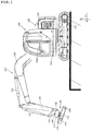
FIG. 1 is a schematic view showing a working machine according to a first embodiment of the present invention. -
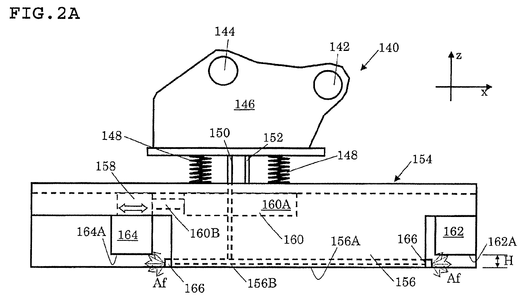
FIG. 2A is a schematic side view showing a radiation detecting attachment used in the working machine ofFIG. 1 . -
FIG 2B is a schematic bottom view showing radiation detecting attachment used in the working machine ofFIG.1 . -
FIG. 3 is a block diagram showing relationships among radiation detectors, a processing device, and a display device used in the working machine ofFIG. 1 . -
FIG. 4A is a schematic view showing radiation detection with the working machine in a structure to be demolished. -
FIG. 4B is a schematic view showing the division with the working machine in a structure to be demolished. -
FIG. 5 is a flow diagram for describing a procedure from the radiation detection to the division in the structure to be demolished, which is shown inFIG. 4 . -
FIG. 6A is a schematic view showing a conveyor and the working machine with the radiation detecting attachment. -
FIG. 6B is a schematic view showing the conveyor with the radiation detecting attachment and the working machine with a working attachment. -
FIG. 6C is a schematic view showing the conveyor on which flexible container packes are disposed and the working machine with the working attachment which sorts the flexible container packs. -
FIG. 7 is a flow diagram for describing a procedure from the preparation of the conveyor belt to the sorting of the flexible container packs, which is shown inFIG. 6 . -
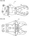
FIG. 8A is a side view showing radiation detecting attachments according to a second embodiment of the present invention. -
FIG. 8B is a side view showing radiation detecting attachments according to a third embodiment of the present invention. -
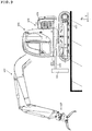
FIG. 9 is a schematic view showing a working machine according to a fourth embodiment of the present invention. - An example of a first embodiment of the present invention will be described below in detail with reference to the drawings.
- First, a configuration of a working
machine 100 according to the present embodiment will be described with reference toFIG. 1 . Note that the workingmachine 100 can be used in the demolition industry, the forest industry, the scrap industry, the waste treatment industry, decontamination work, or the like in an environment with a risk of the presence of radiation due to a radioactive substance or the like leaked from a nuclear power plant or the like. - As shown in
FIG. 1 , the workingmachine 100 includes avehicle body 120, anarm body 127, and aradiation detecting attachment 140. Thevehicle body 120 includes a crawler-type traveling body 122, aturning mechanism 124, and a turningbody 126. The turningbody 126 is configured to be rotatable to the travelingbody 122 by theturning mechanism 124. A driver'scab 126A is established in the turningbody 126. The driver'scab 126A is sealably configured so that radiation can be shielded appropriately while blocking rain and wind. The driver'scab 126A can also be temperature-controlled by an air conditioner. That is, an operator of the workingmachine 100 can operate the workingmachine 100 in a stable manner without being greatly influenced by its working environment. Note that the driver'scab 126A has aprocessing device 170 configured to process outputs fromradiation detectors display device 180 configured to display the processing results produced by the processing device 170 (that is, the driver'scab 126A is equipped with thedisplay device 180 capable of displaying an amount of radiation based on the outputs of theradiation detectors 162 and 164). Theprocessing device 170 and thedisplay device 180 will be described later. Note that the workingmachine 100 may be configured such that the workingmachine 100 is operated remotely from the outside of the vehicle by air and the operator checks the outputs of the radiation detectors from the outside of the vehicle (alternatively, the workingmachine 100 may be unmanned by means of programming, AI, or the like) . Thearm body 127 capable of swinging up and down is attached to the turningbody 126. An air compressor (not shown) is installed in the turningbody 126. An air inlet of the air compressor is provided with an air filter to be able to filter out a radioactive substance wafting through the air. Compressed air provided by the air compressor is supplied, via thearm body 127, to theradiation detecting attachment 140 supported by thearm body 127. While the supply timing of the compressed air is determined by the operator, such timing may automatically coincide with the start of the detection by theradiation detectors - As shown in
FIG. 1 , thearm body 127 includes aboom 128 attached to the turningbody 126, and anarm 132 attached to a leading end of theboom 128. Thearm 132 is configured to be swingable by acylinder mechanism 130. Theradiation detecting attachment 140 is attached removably to a leading end of the arm 132 (that is, theradiation detecting attachment 140 is attached removably to the workingmachine 100 and supported by the workingmachine 100 movably (in such a way as to be capable of moving) when the radiation detecting attachment is attached to the working machine). Theradiation detecting attachment 140 is configured to be capable of swinging by acylinder mechanism 134 via a link mechanism 136 (that is, theradiation detecting attachment 140 is supported by thearm body 127 of the workingmachine 100 swingably (in such a way as to be capable of swinging)). Note that thecylinder mechanisms cylinder mechanism 160 to be described later). - Next, the
radiation detecting attachment 140 will be described mainly with reference toFIGS. 2A and 2B . - The
radiation detecting attachment 140 includes: abracket 146; aframe body 154 supported by thebracket 146 via a plurality of coil springs (elastic members) 148; and fourradiation detectors frame body 154 for detecting radiation from an object W of detection. That is, theradiation detecting attachment 140 supports the fourradiation detectors radiation detectors - The
bracket 146 is provided with apivot shaft 142 and alink shaft 144. Thepivot shaft 142 engages with theaforementioned arm 132, and thelink shaft 144 engages with theaforementioned link mechanism 136. Thus, thebracket 146 is driven to be swingable around thepivot shaft 142. The coil springs 148 are provided at a leading end of thebracket 146, and theframe body 154 is attached to thebracket 146 via the coil springs 148. - The
frame body 154 includes: acasing 156 fixed to and supported by the coil springs 148; and a movingelement 158 supported by thecasing 156 movably. Thecylinder mechanism 160 is disposed in thecasing 156. Acylinder element 160A of thecylinder mechanism 160 is fixed to thecasing 156, and apiston element 160B of thecylinder mechanism 160 supports the movingelement 158. This makes the movingelement 158 movable in an x-direction inFIGS. 2A and 2B . Note that thecasing 156 provide with aflow channel 156B communicated with anair pipe 150, and theflow channel 156B is communicated with fourdischarge nozzles 166. Ahydraulic pipe 152 is communicated with thecylinder mechanism 160. - The
radiation detectors radiation detectors radiation detectors 162 are disposed at two corners of thecasing 156, and theradiation detectors 164 are disposed at both ends of the movingelement 158. Thus, a distance between theradiation detectors 162 and theradiation detectors 164 is changeable (can be modified) by thecylinder mechanism 160. Alower surface 156A of the casing is protruded more than the detection surfaces 162A and 164A by a distance H, thereby providing a level difference between thelower surface 156A of the casing and the detection surfaces 162A and 164A. As a result, even when thelower surface 156A of the casing is brought into contact with the object W of detection in a case where the object W of detection has a planar shape, a gap corresponding to the distance H can be provided between the detection surfaces 162A and 164A of theradiation detectors radiation detectors discharge nozzles 166 for discharging, to the detection surfaces 162A and 164A, the compressed air supplied from thevehicle body 120 are provided. More specifically, theradiation detecting attachment 140 is configured to include the fourdischarge nozzles 166 disposed to be capable of replacing pre-replacement air Ab between theradiation detectors discharge nozzles 166 are configured to discharge post-replacement air Af having a reduced amount of the radioactive substance contained in the pre-replacement air Ab. In the present embodiment, theradiation detectors processing device 170 and thedisplay device 180 via a wireless communication unit (not shown) (this may be implemented via wire communication). The wireless communication unit enables the operator to start and end the detection of theradiation detectors radiation detectors cab 126A. Since the outputs are provided via wireless communication in the present embodiment, theradiation detectors vehicle body 120 may be used, or a dedicated rechargeable battery may be used as a power source for theradiation detectors radiation detectors detection surfaces radiation detectors radiation detectors - Next, the
radiation detectors processing device 170, and thedisplay device 180 will be described mainly with reference toFIG. 3 . Note that input unit (not shown) is provided in theprocessing device 170, thereby allowing the operator to instruct theradiation detectors - The
processing device 170 receives data on the amounts of radiation detected by theradiation detectors processing device 170 includes a radiationamount computing unit 172, amapping processing unit 174, and a sortingdetermination unit 176. - The radiation
amount computing unit 172 obtains a total amount of radiation Ct that can be detected by the entireradiation detecting attachment 140 on the basis of a positional relationship of theradiation detectors radiation detectors radiation detectors radiation detectors amount computing unit 172 can obtain the total amount of radiation Ct that can be detected by the total detection area S1 according to Expression (1).
- That is, in the
radiation detecting attachment 140, the total detection area S1 can be changed (modified) by moving the movingelement 158 so that the detection surface is modified to have a size suitable for the object W of detection. Note that the position of the movingelement 158 can be obtained by monitoring a supplied oil amount for driving the cylinder mechanism 160 (or an encoder or the like). - When the object W of detection is in an individually-separated form (such as a flexible container pack FP to be described later), the radiation
amount computing unit 172 can obtain a specific amount of radiation Ci of the object W of detection by inputting a proportion of the total detection area S1 that covers the entire object W of detection (such as a solid angle). - The
mapping processing unit 174 connects the total amountof radiation Ct to the detection area MA of the object W of detection. For example, a positioning device (navigation system) for pinpointing the current location on a map on the basis of a GPS signal is incorporated into the workingmachine 100. Themapping processing unit 174 can develop the map data. Themapping processing unit 174 further connects, to the map, data on the shapes of individual structures (such as private houses, apartment houses, public facilities and utilities, and infrastructural facilities and utilities) obtained by a laser scanner or a camera (2D or 3D), or from design data (the data on the shapes of individual structures may be inputted in the form of electronic data via an external interface provided in the processing device 170). Themapping processing unit 174 performs mesh processing on the data on the shapes of the individual structures according to the detection area MA having a size corresponding to the total detection area S1 of theradiation detecting attachment 140. Themapping processing unit 174 then assigns the total amount of radiation Ct to the detection area MA corresponding to the detection position of theradiation detecting attachment 140. The detection position of theradiation detecting attachment 140 in this case can be obtained by monitoring a supplied oil amount for driving each cylinder mechanism (or an encoder or the like). Needless to say, the operator himself or herself may manually determine the detection area MA corresponding to the detection position of theradiation detecting attachment 140. Thus, themapping processing unit 174 can obtain radiation amount distributions ranging from a radiation amount distribution in a specific individual structure to a radiation amount distribution over a wide range such as a district or a region. - The sorting
determination unit 176 determines whether the total amount of radiation Ct or the specific amount of radiation Ci exceeds a reference amount Cb of radiation. Based on the determination result, the sortingdetermination unit 176 changes the display information and gives a guidance for aftertreatment. When the specific amount of radiation Ci exceeds the reference radiation amount (e.g., 8000 becquerel per 1 Kg) in unit mass, for example, it is determined as radioactive waste by the sortingdetermination unit 176. Mass data may be estimated in each dividable weight of the object W of detection, or may use outputs of a weight sensor such as a load cell (the weight sensor may be incorporated into a part of a grapple GP or a conveyor BC). Note that the total amount of radiation Ct may be used for sorting determination by converting it in terms of unit area. - The
display device 180 is connected to theprocessing device 170 and capable of directly displaying the amounts of radiation detected by theindividual radiation detectors display unit 182 thereof. Simultaneously, thedisplay unit 182 can also display the results obtained by the radiationamount computing unit 172, themapping processing unit 174, and the sorting determination unit 176 (that is, mapping associating the amount of radiation with the detection area MA of the object W of detection can be displayed at the display device 180). These results may be displayed not only in numerical values but also by color coding. Note that thedisplay device 180 may also serve as a display device for the positioning device. - Next, a sorting procedure of sorting the object W of detection based on the amount of radiation with the
radiation detecting attachment 140 will be described with reference toFIGS. 4 and5 . Note that the object W of detection in this case is a structure BB to be demolished, which is shown inFIG. 4 . - First, the
radiation detecting attachment 140 is attached to the working machine 100 (Step S2 inFIG. 5 ). Theradiation detecting attachment 140 is then brought closer to the detection area MA (Step S4 inFIG. 5 ). More specifically, theradiation detecting attachment 140 is supported by the workingmachine 100, and theradiation detecting attachment 140 is brought closer to the detection area MA of the structure BB to be demolished. At this time, the lower surface of the frame body 154 (thelower surface 156A of the casing) in theradiation detecting attachment 140 is brought into contact with the detection area MA. - Next, the pre-replacement air Ab is replaced by causing the
discharge nozzles 166 to discharge the compressed air (Step S6 inFIG. 5 ). More specifically, the pre-replacement air Ab (present) between theradiation detectors - Next, the total amount (amount) of radiation Ct of the detection area MA is obtained (
FIG. 4A and Step S8 inFIG. 5 ). More specifically, the total amount of radiation Ct of the detection area MA corresponding to the total detection area S1 is obtained by the radiationamount computing unit 172 on the basis of the outputs of theradiation detectors mapping processing unit 174. - Next, mapping associating the obtained total amount of radiation Ct with the detection area MA is displayed at the display device 180 (Step S10 in
FIG. 5 ). - Next, it is determined whether all detection areas MA have been subjected to the detection. If the detection on the all detection areas MA has not been finished yet (No in Step S12 in
FIG. 5 ), the detection is started on another detection area MA (Steps S4 to S10 inFIG. 5 ). - If the all detection areas MA have been subjected to the detection (Yes in Step S12 in
FIG. 5 ), theradiation detecting attachment 140 is replaced by high-powered cross cutter (coarse crushing equipment: working attachment) CT (Step S14 inFIG. 5 ). More specifically, theradiation detecting attachment 140 is detached from the workingmachine 100, and the high-powered cross cutter CT, capable of dividing the structure BB to be demolished into each of the detection areas MA, is attached to the working machine 100 (this transforms the workingmachine 100 into a working machine 101). - Next, the structure BB to be demolished is divided with the high-powered cross cutter CT (
FIG. 4B and Step S16 inFIG. 5 ). More specifically, the structure BB to be demolished is divided with the high-powered cross cutter CT in accordance with the obtained total amounts of radiation Ct. Once divided, the segments of the structure BB to be demolished, having been divided in accordance with the level of the total amounts of radiation Ct, are placed at different locations in order to prevent a level of the total amount of radiation Ct mixing with one another. Also with regard to the dividing procedure, segments of the structure BB to be demolished, having equivalent total amounts of radiation Ct, are divided together as much as possible in accordance with the total amounts of radiation Ct. Note that a mechanism for discharging water jet capable of dividing the structure BB to be demolished into each of the detection areas MA may be attached to the working machine in place of the high-powered cross cutterCT. - As just described, by using the
radiation detecting attachment 140 in the demolition of the structure BB to be demolished, the distribution of the amounts of radiation for all of the structure BB to be demolished can be found out before the demolition work. This allows for efficient demolition work and quick sorting. - The
radiation detecting attachment 140 is detached from the workingmachine 100, high-powered cross cutterCT is attached to the workingmachine 100, and the structure BB to be demolished is divided with the high-powered cross cutter CT in accordance with the obtained total amounts of radiation Ct. Therefore, thevehicle body 120 itself of the workingmachine 100 is shared with the workingmachine 101. Thus, the structure BB to be demolished can be easily sorted even in a narrow working site. - Next, a sorting procedure of sorting another object W of detection on the basis of an amount of radiation with the
radiation detecting attachment 140 will be described with reference toFIGS. 6 and7 . Note that the object W of detection in this case is a flexible container pack FP shown inFIG. 6C . The flexible container pack FP contains, for example, contaminated soil, contaminated plants, or the like resulting from decontamination work, or contaminated waste produced by demolition work or the like. - First, a conveyor (conveying unit) BC capable of conveying a plurality of flexible container packs FP is prepared (
FIG. 6A and Step S20 inFIG. 7 ). At this time, a proportional rate of theradiation detecting attachment 140 that covers the flexible container pack FP is inputted to theprocessing device 170, for example. While the conveyor BC moves the flexible container pack FP simply in one direction without changing its physical orientation in the present embodiment, the present invention is not limited thereto. The conveyor BC may be configured to move the flexible container pack FP in one direction while rotating the flexible container pack FP and to cause the flexible container pack FP to be constantly in contact with one end of the conveyor BC (the side on which theradiation detecting attachment 140 is disposed). - Next, the
radiation detecting attachment 140 is detached from the working machine 100 (Step S22 inFIG. 7 ). Thereafter, the grapple GP capable of supporting the flexible container pack FP is attached to the working machine 100 (Step S24 inFIG. 7 ). This transforms the workingmachine 100 into a workingmachine 102. Note that the grapple GP is provided with a weight sensor and thus includes a configuration for measuring a weight of the supported flexible container pack FP and sending the measured result to the processing device 170 (the working attachment may be a hook, or the like, capable of hanging the flexible container pack FP instead of the grapple GP) . - At the same time, the
radiation detecting attachment 140 is disposed near the conveyor BC so that radiation of the plurality of flexible container packs FP moving on the conveyor BC can be detected sequentially (FIG. 6B and Step S26 inFIG. 7 ). Thereafter, the place at which theradiation detecting attachment 140 is disposed is covered with a box-shaped cover CV (The box-shaped cover CV is provided with, for example, openable and closable doors through which the flexible container pack FP can pass. More specifically, once a single flexible container pack FP moves and enters into the box-shaped cover CV, the openable and closable doors are closed. After its amount of radiation is detected, the openable and closable doors are opened so that the flexible container pack FP moves and exits from the box-shaped cover CV. Needless to say, no box-shaped cover CV may be provided.). Note that theradiation detecting attachment 140 is controlled from the workingmachine 102. In the present embodiment, in disposing theradiation detecting attachment 140 near the conveyor BC with the workingmachine 100, theradiation detecting attachment 140 is detached and installed at the same place. The present invention, however, is not limited thereto. Theradiation detecting attachment 140 detached at another place may be disposed and installed near the conveyor BC with the grapple GP of the workingmachine 102 or by hand. While only oneradiation detecting attachment 140 is disposed on one side of the conveyor BC in the present embodiment, the present invention is not limited thereto. With the use of a plurality of radiation detecting attachments, the radiation detecting attachments may be disposed on the both sides of the conveyor belt BC or above the conveyor belt BC. - Next, the conveyor BC is driven, and the plurality of flexible container packs FP are disposed on the conveyor BC with the grapple GP in order to detect radiation (Step S28 in
FIG. 7 ). Note that the conveyor BC can be driven, for example, by remotely controlling its start, end, and conveying speed as appropriate. - Next, to detect an amount of radiation for each of the flexible container packs FP, the openable and closable doors are closed when the flexible container pack FP enters into the box-shaped cover CV, and at least the pre-replacement air Ab between the
radiation detectors FIG. 7 ). It is more preferable that the pre-replacement air Ab be replaced for all the air inside of the box-shaped cover CV. - Next, radiation is detected for each of the plurality of flexible container packs FP with the
radiation detecting attachment 140. Data on the amounts of radiation is then transmitted to theprocessing device 170 from theradiation detecting attachment 140. The transmitted radiation amount data is processed by the radiationamount computing unit 172 of theprocessing device 170 to obtain a specific amount of radiation (amount) Ci for each of the flexible container packs FP (Step S32 inFIG. 7 ). Thereafter, thedisplay device 180 displays the obtained specific amount of radiation Ci and its process procedure, for example, for each of the flexible container packs FP on the basis of outputs of the sorting determination unit 176 (Step S34 inFIG. 7 ). - Next, the flexible container pack FP having exited from the box-shaped cover CV is sorted with the grapple GP on the basis of the obtained specific amount of radiation Ci (
FIG. 6C and Step S36 inFIG. 7 ). For example, the workingmachine 102 can dispose the flexible container packs FP while varying placement locations between PL1 and PL2 depending on a level of the specific amount of radiation Ci as shown inFIG. 6C . - As just described, in evaluating amounts of radiation of the flexible container packs FP, the use of the conveyor BC and the detached
radiation detecting attachment 140 enables the flexible container packs FP to be handled in a conveyer system, without the flexible container packs FP being individually moved and processed with the working machine one by one. In other words, efficient detection and sorting can be achieved in the handling of a large number of flexible container packs FP. - The
radiation detecting attachment 140 is detached from the workingmachine 100, the grapple GP capable of supporting the flexible container pack FP is attached to the working machine 100 (this transforms the workingmachine 100 into the working machine 102), and the plurality of flexible container packs FP are disposed on the conveyor BC with the grapple GP in order to detect radiation. Therefore, thevehicle body 120 itself of the workingmachine 102 that disposes the flexible container packs FP on the conveyor BC is shared with the workingmachine 100 that detects and processes amounts of radiation. Thus, the flexible container packs FP can be disposed on the conveyor BC even in a narrow working site. Note that the present invention is not limited thereto. In order to achieve quick sorting for a large number of flexible container packs FP, a plurality of flexible container packs FP may be disposed on the conveyor BC with another working machine. - Furthermore, the obtained specific amount of radiation Ci is displayed for each of the flexible container packs FP. This allows the flexible container pack FP to be sorted easily in accordance with the specific amount of radiation Ci.
- The object W of detection is sorted with the grapple GP in accordance with the obtained specific amount of radiation Ci. Therefore, the
vehicle body 120 itself of the workingmachine 102 that disposes the flexible container packs FP on the conveyor BC and sorts the flexible container packs FP on the conveyor BC is shared with the workingmachine 102 that detects and processes amounts of radiation. Thus, the flexible container packs FP can be easily moved from the conveyor BC and sorted even in a narrow working site. Note that the present invention is not limited thereto. In order to achieve quick sorting for a large number of flexible container packs FP, a plurality of flexible container packs FP on the conveyor BC may be sorted with another working machine. - In the present embodiment, the
radiation detecting attachment 140 including the fourradiation detectors machine 100. Furthermore, theradiation detecting attachment 140 is supported by the working machine 100movably. This imposes less limitation on the size of the object W of detection and enables a distance to the object W of detection and a positional relationship with the object W of detection to be adjusted appropriately. Moreover, since the need for personnel to detect radiation can be eliminated, cost reduction in work in an environment with a risk of the presence of radiation due to a radioactive substance or the like leaked from a nuclear power plant or the like can be promoted. - In the present embodiment, the
radiation detecting attachment 140 is supported by thearm body 127 of the workingmachine 100 swingably. This can further broaden the positional flexibility of theradiation detecting attachment 140. - In the present embodiment, a distance between the two
radiation detectors 164 and the other tworadiation detectors 162 is changeable . Thus, radiation can be detected efficiently by changing a clearance between theradiation detectors - In the present embodiment, the four
radiation detectors radiation detectors radiation detectors - In the present embodiment, there are provided the four
discharge nozzles 166 disposed to be capable of replacing the pre-replacement air Ab between theradiation detectors discharge nozzles 166. Thus, even in an environment with a high air dose, for example, the low-amount of radiation from the object W of detection can be detected. That is, the amount from radiation of the object W itself of detection can be accurately detected by reducing the influence of the air dose. Note that the present invention is not limited thereto. No such discharge nozzles may be provided. Alternatively, not a single but two discharge nozzles may be provided for each of the radiation detectors. Alternatively, a single discharge nozzle may be disposed to be used for all of the radiation detectors. Alternatively, the discharge nozzle may be configured to be integral with not the frame body but the radiation detector. - In the present embodiment, the driver's
cab 126A is equipped with thedisplay device 180 capable of displaying amounts of radiation based on outputs of theradiation detectors cab 126A can directly check the amounts of radiation without successively moving to the position of theradiation detecting attachment 140 to check the outputs of theradiation detectors - In the present embodiment, mapping associating the total amounts of radiation Ct with the detection areas MA of the object W of detection, such as the structure BB to be demolished, can be displayed at the
display device 180. Thus, a level of such an amount of radiation can be determined for each of the detection areas MA. Therefore, in demolishing the object W of detection, a required space to dispose waste resulting from the demolition, its demolition procedure, or the like can be predicted before starting the demolition. That is, there is no need to separately check the demolition procedure or the amounts of radiation after the demolition, thereby enabling an improvement in working efficiency. Note that the present invention is not limited thereto. No mapping display for the total amounts of radiation Ct may be provided. - That is, the use of the
radiation detecting attachment 140 in the present embodiment makes it possible to use theradiation detectors - While the present invention has been described with reference to the first embodiment, the present invention is not limited to the first embodiment. That is, it is needless to say that modifications and design changes are possible without departing from the scope of the present invention.
- For example, while the
radiation detecting attachment 140 includes the fourradiation detectors radiation detector 162 and theradiation detector 164 is changeable in the x-direction on the x-y plane in the above-described embodiment, the present invention is not limited thereto. For example, the radiation detecting attachment may be configured as in a second embodiment and a third embodiment shown inFIGS. 8A and 8B , respectively. In the second and third embodiments, radiation detecting attachments each include a plurality of claw members capable of coming closer to each other and separating from each other. Specifically, in the second embodiment shown inFIG. 8A , clawmembers rotating mechanism 248 are grasping members for grasping a specified object, and aradiation detecting attachment 240 constitutes a grapple GP. In the third embodiment shown inFIG. 8B ,claw members radiation detecting attachment 340 constitutes a cutter (theradiation detecting attachment 340 may be high-powered cross cutter CT, normal cross cutter, a crusher, or the like). In such cases, a single radiation detector may be disposed at only any one of a plurality ofpositions different claw members 256 and 258 (356 and 358), a clearance between the radiation detectors may be modified by opening and closing theclaw members 256 and 258 (356 and 358). With the use of theclaw members 256 and 258 (356 and 358) shown inFIGS. 8A and 8B , the radiation detecting attachment 240 (340) can function also as a conventional working attachment such as the cutter or the grapple GP. By grasping the object W of detection with theclaw members 256 and 258 (356 and 358), for example, a distance to the object W of detection can be stabilized, and the object W of detection can be accurately identified for the detected amount of radiation. Note that the present invention is not limited thereto. The opening and closing form of claw members may be configured in such a manner that the claw members come closer to one another from a plurality of axial directions as in what is called a tulip shape. Alternatively, the radiation detecting attachment may include a mechanism for discharging water jet capable of cutting a specified object. - While the
radiation detecting attachment 140 is supported by thearm body 127 of the workingmachine 100 swingably in the above-described embodiment, the present invention is not limited thereto. For example, the radiation detecting attachment may be configured as in a fourth embodiment shown inFIG. 9 . In the fourth embodiment, aradiation detecting attachment 440 is supported by a linear-motion mechanism 425 so as to be capable of being translated with respect to aturning body 426, rather than being supported by anarm body 427 swingably. - Also, in the fourth embodiment, a working
machine 400 is configured to simultaneously include theradiation detecting attachment 440 and a grapple GP capable of supporting an object W of detection and theradiation detecting attachment 440. This enables objects W of detection to be disposed on a conveyor BC with the equipped grapple GP in order to detect radiation. That is, no other working machine is required, and replacement work between theradiation detecting attachment 440 and the grapple GP can be eliminated. Thus, the objects W of detection can be easily moved from the conveyor BC and sorted even in a narrow working site. - Assume that the working
machine 400 includes high-powered cross cutter CT (it may be a cutter) instead of the grapple GP inFIG. 9 . In this case, the object W of detection can be divided with the high-powered cross cutter CT in accordance with the obtained amounts of radiation. That is, no other working machine is required, and replacement work between theradiation detecting attachment 440 and the CT can be eliminated. Thus, the objects W of detection can be quickly sorted even in a narrow working site. - Note that the working machine may include a plurality of arm bodies, and the grapple GP (or the high-powered cross cutter CT or the cutter) and the radiation detecting attachment may be supported by the different arm bodies.
- While the radiation detectors are scintillation detectors in the above-described embodiment, the present invention is not limited thereto. For example, a fluoroglass dosimeter or a thermoluminescence dosimeter utilizing a fluorescence action, a photographic film, a semiconductor dosimeter, a chemical dosimeter, discharge ionization chamber dosimeter, a GM counter, or the like may be employed as a radiation detector.
- The present invention can be widely applied to the demolition industry, the forest industry, the scrap industry, the waste treatment industry, decontamination work, or the like, having a risk of radiation contamination.
-
- 100, 101, 102, 400 ... working machine
- 120, 420 ... vehicle body
- 122, 422 ... traveling body
- 124, 424 ... turning mechanism
- 126, 426 ... turning body
- 126A ... driver's cab
- 127, 427 ... arm body
- 128 ... boom
- 130, 134, 160 ... cylinder mechanism
- 132 ... arm
- 136 ... link mechanism
- 140, 240, 340, 440 ... radiation detecting attachment
- 142 ... pivot shaft
- 144 ... link shaft
- 146, 246, 346 ... bracket
- 148 ... coil spring
- 150 ... air pipe
- 152 ... hydraulic pipe
- 154, 254, 354 ... frame body
- 156 ... casing
- 156A ... lower surface of casing
- 156B ... flow channel
- 158 ... moving element
- 160A ... cylinder element
- 160B ... piston element
- 162, 164 ... radiation detector
- 162A, 164A ... detection surface
- 166 ... discharge nozzle
- 170 ... processing device
- 172 ... radiation amount computing unit
- 174 ... mapping processing unit
- 176 ... sorting determination unit
- 180 ... display device
- 182 ... display unit
- 248 ... rotating mechanism
- 256, 258, 356, 358 ... claw member
- 262A, 262B, 262C, 263, 264A, 264B, 264C, 362, 363, 364 ... position (where a radiation detector may be disposed)
- 425 ... linear-motion mechanism
- Ab ... pre-replacement air
- Af ... post-replacement air
- BB ... structure to be demolished
- BC ... conveyor
- CT ... high-powered cross cutter CV ... box-shaped cover
- FP ... flexible container pack
- GP ... grapple
- MA ... detection area
- PL1, PL2 ... placement location
- W ... object of detection
Claims (20)
- A radiation detecting attachment comprising one or more radiation detectors configured to detect radiation from an object of detection, attached removably to a working machine, wherein
the radiation detecting attachment is supported by the working machine movable when the radiation detecting attachment is attached to the working machine. - The radiation detecting attachment according to claim 1, wherein the radiation detecting attachment is supported by an arm body of the working machine swingably.
- The radiation detecting attachment according to claim 1 or 2, wherein, when a plurality of the radiation detectors are included, a distance between at least one radiation detector and another radiation detector is changeable.
- The radiation detecting attachment according to any one of claims 1 to 3, comprising a plurality of claw members capable of coming closer to each other and separating from each other.
- The radiation detecting attachment according to any one of claims 1 to 4, wherein at least one of the radiation detectors is supported via an elastic member.
- The radiation detecting attachment according to any one of claims 1 to 5, comprising one or more discharge nozzles disposed to be capable of replacing pre-replacement air between the radiation detector and a detection area of the object of detection, wherein
post-replacement air having a reduced amount of a radioactive substance contained in the pre-replacement air is discharged from the one or more discharge nozzles. - The working machine to which the radiation detecting attachment according to any one of claims 1 to 6 is attached.
- The working machine according to claim 7, comprising a driver's cab equipped with a display device capable of displaying an amount of radiation based on an output of the radiation detector.
- The working machine according to claim 8, wherein the display device can display mapping associating the amount of radiation with the detection area of the object of detection.
- A sorting method for sorting, with a radiation detecting attachment including one or more radiation detectors configured to detect radiation from an object of detection, attached removably to a working machine, the object of detection on a basis of an amount of the radiation, the method comprising:a step of supporting the radiation detecting attachment by the working machine and bringing the radiation detecting attachment closer to each of detection areas of the object of detection; anda step of obtaining an amount of radiation of the detection area on a basis of an output of the radiation detector.
- The sorting method according to claim 10, comprising: a step of replacing pre-replacement air between the radiation detector and the detection area with post-replacement air having a reduced amount of a radioactive substance contained in the pre-replacement air before obtaining the amount of radiation of the detection area.
- The sorting method according to claim 10 or 11, comprising a step of displaying mapping associating the obtained amount of radiation with the detection area.
- The sorting method according to any one of claims 10 to 12, comprising:a step of detaching the radiation detecting attachment from the working machine and attaching a working attachment, capable of dividing the object of detection into each of the detection areas, to the working machine; anda step of dividing the object of detection with the working attachment in accordance with the obtained amount of radiation.
- The sorting method according to any one of claims 10 to 12, comprising, when the working machine simultaneously includes the radiation detecting attachment and a working attachment capable of dividing the object of detection into each of the detection areas, a step of dividing the obj ect of detection with the working attachment in accordance with the obtained amount of radiation.
- A sorting method for sorting, with a radiation detecting attachment including one or more radiation detectors configured to detect radiation from an object of detection, attached removably to a working machine, the object of detection on a basis of an amount of the radiation, the method comprising:a step of preparing a conveying unit capable of conveying a plurality of the objects of detection;a step of detaching the radiation detecting attachment from the working machine and disposing the radiation detecting attachment near the conveying unit so that radiation of the plurality of the objects of detection moving on the conveying unit can be detected sequentially; anda step of obtaining an amount of radiation for each of the plurality of the objects of detection moving on the conveying unit.
- The sorting method according to claim 15, comprising a step of replacing, when obtaining the amount of radiation for each of the objects of detection, pre-replacement air between the radiation detector and the object of detection with post-replacement air having a reduced amount of a radioactive substance contained in the pre-replacement air.
- The sorting method according to claim 15 or 16, comprising:a step of detaching the radiation detecting attachment from the working machine and attaching a working attachment, capable of supporting the object of detection, to the working machine; anda step of disposing the plurality of the objects of detection on the conveying unit with the working attachment in order to detect the radiation.
- The sorting method according to claim 15 or 16, comprising, when the working machine simultaneously includes the radiation detecting attachment and a working attachment capable of supporting the object of detection, a step of disposing the plurality of the objects of detection on the conveying unit with the equipped working attachment in order to detect the radiation.
- The sorting method according to any one of claims 15 to 18, comprising a step of displaying the obtained amount of radiation for each of the objects of detection.
- The sorting method according to any one of claims 15 to 19, comprising a step of sorting the object of detection with the working attachment in accordance with the obtained amount of radiation.
Applications Claiming Priority (2)
| Application Number | Priority Date | Filing Date | Title |
|---|---|---|---|
| JP2017012530A JP6881736B2 (en) | 2017-01-26 | 2017-01-26 | Radiation detection attachments, work machines, and sorting methods |
| PCT/JP2018/002005 WO2018139456A1 (en) | 2017-01-26 | 2018-01-23 | Radiation detecting attachment, working machine, and sorting method |
Publications (3)
| Publication Number | Publication Date |
|---|---|
| EP3575834A1 true EP3575834A1 (en) | 2019-12-04 |
| EP3575834A4 EP3575834A4 (en) | 2020-11-11 |
| EP3575834B1 EP3575834B1 (en) | 2026-02-25 |
Family
ID=62979402
Family Applications (1)
| Application Number | Title | Priority Date | Filing Date |
|---|---|---|---|
| EP18744169.6A Active EP3575834B1 (en) | 2017-01-26 | 2018-01-23 | System comprising a radiation detecting attachment and a working machine, and method for dividing an object |
Country Status (4)
| Country | Link |
|---|---|
| US (1) | US11415709B2 (en) |
| EP (1) | EP3575834B1 (en) |
| JP (1) | JP6881736B2 (en) |
| WO (1) | WO2018139456A1 (en) |
Families Citing this family (5)
| Publication number | Priority date | Publication date | Assignee | Title |
|---|---|---|---|---|
| JP7212880B2 (en) * | 2018-09-27 | 2023-01-26 | 株式会社トプコン | Nondestructive inspection system and nondestructive inspection method |
| AT521936B1 (en) * | 2018-12-12 | 2021-09-15 | Lexa Dr Dusan | Device and method for the non-destructive analysis of a radioactive waste package |
| JP7411497B2 (en) * | 2020-04-28 | 2024-01-11 | 株式会社クボタ | Grapple, contained material discharge device, and contained material discharge method |
| JP7345231B2 (en) * | 2020-05-15 | 2023-09-15 | 大成建設株式会社 | Mounting structure of radioisotope measuring device |
| GB202211434D0 (en) * | 2022-08-05 | 2022-09-21 | Create Tech Limited | Radiation imaging robot |
Family Cites Families (12)
| Publication number | Priority date | Publication date | Assignee | Title |
|---|---|---|---|---|
| JPS5553448U (en) * | 1978-10-06 | 1980-04-10 | ||
| FR2641380B1 (en) * | 1988-12-30 | 1991-04-26 | Mokta Cie Fse | DEVICE FOR MEASURING THE RADIOACTIVITY OF A MINERAL LOAD ON AN EXTRACTION MACHINE SUCH AS A BUCKET SHOVEL |
| US5330142A (en) * | 1993-03-29 | 1994-07-19 | Hot-Sci, Inc. | Mobile support frame for radiation detection equipment |
| JPH0894399A (en) * | 1994-09-28 | 1996-04-12 | Toshiba Eng & Constr Co Ltd | Mobile inspection device |
| US6448564B1 (en) | 2000-05-30 | 2002-09-10 | Gtsd Sub Iii | Apparatus, methods, and systems for assaying materials |
| WO2011143151A1 (en) | 2010-05-10 | 2011-11-17 | Nucor Corporation | Centralized detection of radiation in multiple facilities |
| GB2489663B (en) | 2011-03-21 | 2015-07-08 | Bamford Excavators Ltd | A working machine hitch arrangement |
| JP2012229945A (en) * | 2011-04-25 | 2012-11-22 | Hitachi Constr Mach Co Ltd | Working machine equipped with radiation meter |
| JP5753763B2 (en) * | 2011-10-26 | 2015-07-22 | 三井住友建設株式会社 | Radioactive material contaminated soil removal method and radioactive material contaminated soil removal management system |
| JP2014020900A (en) * | 2012-07-18 | 2014-02-03 | Ihi Construction Machinery Ltd | Self-propelled dosimetry device |
| JP6025527B2 (en) * | 2012-11-28 | 2016-11-16 | 鈴健興業株式会社 | Waste sorting facility and waste sorting method |
| JP2015175137A (en) * | 2014-03-14 | 2015-10-05 | 日立建機株式会社 | Fork and hydraulic circuit for the same |
-
2017
- 2017-01-26 JP JP2017012530A patent/JP6881736B2/en active Active
-
2018
- 2018-01-23 WO PCT/JP2018/002005 patent/WO2018139456A1/en not_active Ceased
- 2018-01-23 EP EP18744169.6A patent/EP3575834B1/en active Active
- 2018-01-23 US US16/481,393 patent/US11415709B2/en active Active
Also Published As
| Publication number | Publication date |
|---|---|
| JP2018119890A (en) | 2018-08-02 |
| EP3575834B1 (en) | 2026-02-25 |
| EP3575834A4 (en) | 2020-11-11 |
| WO2018139456A1 (en) | 2018-08-02 |
| JP6881736B2 (en) | 2021-06-02 |
| US11415709B2 (en) | 2022-08-16 |
| US20190391279A1 (en) | 2019-12-26 |
Similar Documents
| Publication | Publication Date | Title |
|---|---|---|
| EP3575834B1 (en) | System comprising a radiation detecting attachment and a working machine, and method for dividing an object | |
| CN110319888B (en) | Petrochemical inspection robot and working method thereof | |
| CN111209610A (en) | Radiation protection intelligent shielding system and method | |
| JP2016080586A (en) | Radiation measurement system and radiation measurement method | |
| GB2586045A (en) | Surveying and dismantling system | |
| JP2012229945A (en) | Working machine equipped with radiation meter | |
| EP2515310A2 (en) | Shielded protective tent assembly | |
| KR101973035B1 (en) | Classification device using radiation measurement systems | |
| CN102265180A (en) | Detector device for monitoring scrap metal for radioactive components | |
| Yoshida et al. | Development of plutonium fuel facility decommissioning technology to accelerate glovebox dismantling and reduce air-fed suits based operations | |
| CN104947952B (en) | Ex-service biological shield demounting process of swimming pool reactors | |
| KR101135850B1 (en) | Remote-wireless weighing scale apparatus for high radiation in hot cell | |
| US5203644A (en) | System to control contamination during retrieval of buried TRU waste | |
| WO2025251163A1 (en) | System and methods for monitoring works or a processing device | |
| Dosmukhamedov et al. | The concept of building a robotic system for monitoring the quality of ores in a natural occurrence | |
| RU94557U1 (en) | LIFTING MACHINE | |
| EP4575423A1 (en) | A method, an apparatus and a program code for indicating a residual load | |
| Tibrea et al. | Robotics in hazardous environments-real deployments by the savannah river national lab | |
| Megson-Smith et al. | Radiological Imaging of the Chornobyl Reactor 4 Shelter with YanDavos II–22371 | |
| Ivanov et al. | Remote measurements of radioactivity distribution with Brokk robotic system | |
| Müller | Long range manipulator development and experiments with dismantling tools | |
| Norman | BARRNON INTEGRATED DECOMMISSIONING SYSTEM (BIDS) | |
| JP2006010108A (en) | Structure for excavation work of containers containing chemical weapons or toxic chemicals | |
| Kwok | Research on the use of robotics in hazardous environments at Sandia National Laboratories | |
| Bacca et al. | An improved out-cell to in-cell rapid transfer system at the HFEF/south [hot fuel examination facility-south] |
Legal Events
| Date | Code | Title | Description |
|---|---|---|---|
| STAA | Information on the status of an ep patent application or granted ep patent |
Free format text: STATUS: THE INTERNATIONAL PUBLICATION HAS BEEN MADE |
|
| PUAI | Public reference made under article 153(3) epc to a published international application that has entered the european phase |
Free format text: ORIGINAL CODE: 0009012 |
|
| STAA | Information on the status of an ep patent application or granted ep patent |
Free format text: STATUS: REQUEST FOR EXAMINATION WAS MADE |
|
| 17P | Request for examination filed |
Effective date: 20190726 |
|
| AK | Designated contracting states |
Kind code of ref document: A1 Designated state(s): AL AT BE BG CH CY CZ DE DK EE ES FI FR GB GR HR HU IE IS IT LI LT LU LV MC MK MT NL NO PL PT RO RS SE SI SK SM TR |
|
| AX | Request for extension of the european patent |
Extension state: BA ME |
|
| DAV | Request for validation of the european patent (deleted) | ||
| DAX | Request for extension of the european patent (deleted) | ||
| A4 | Supplementary search report drawn up and despatched |
Effective date: 20201008 |
|
| RIC1 | Information provided on ipc code assigned before grant |
Ipc: G01T 7/00 20060101AFI20201002BHEP Ipc: E02F 3/36 20060101ALI20201002BHEP Ipc: E04G 23/08 20060101ALI20201002BHEP Ipc: E02F 9/26 20060101ALI20201002BHEP Ipc: G21F 9/30 20060101ALI20201002BHEP Ipc: E04G 23/02 20060101ALI20201002BHEP Ipc: G01T 7/02 20060101ALI20201002BHEP Ipc: G01V 5/02 20060101ALI20201002BHEP Ipc: G01T 1/167 20060101ALI20201002BHEP Ipc: B02C 1/06 20060101ALI20201002BHEP |
|
| STAA | Information on the status of an ep patent application or granted ep patent |
Free format text: STATUS: EXAMINATION IS IN PROGRESS |
|
| 17Q | First examination report despatched |
Effective date: 20220610 |
|
| GRAP | Despatch of communication of intention to grant a patent |
Free format text: ORIGINAL CODE: EPIDOSNIGR1 |
|
| STAA | Information on the status of an ep patent application or granted ep patent |
Free format text: STATUS: GRANT OF PATENT IS INTENDED |
|
| INTG | Intention to grant announced |
Effective date: 20251023 |
|
| GRAS | Grant fee paid |
Free format text: ORIGINAL CODE: EPIDOSNIGR3 |
|
| GRAA | (expected) grant |
Free format text: ORIGINAL CODE: 0009210 |
|
| STAA | Information on the status of an ep patent application or granted ep patent |
Free format text: STATUS: THE PATENT HAS BEEN GRANTED |
|
| AK | Designated contracting states |
Kind code of ref document: B1 Designated state(s): AL AT BE BG CH CY CZ DE DK EE ES FI FR GB GR HR HU IE IS IT LI LT LU LV MC MK MT NL NO PL PT RO RS SE SI SK SM TR |
|
| REG | Reference to a national code |
Ref country code: CH Ref legal event code: F10 Free format text: ST27 STATUS EVENT CODE: U-0-0-F10-F00 (AS PROVIDED BY THE NATIONAL OFFICE) Effective date: 20260225 Ref country code: GB Ref legal event code: FG4D |
|
| REG | Reference to a national code |
Ref country code: DE Ref legal event code: R096 Ref document number: 602018089395 Country of ref document: DE |
|
| REG | Reference to a national code |
Ref country code: IE Ref legal event code: FG4D |