EP3575770A1 - Method for treating volatile liquid and device for treating liquid - Google Patents
Method for treating volatile liquid and device for treating liquid Download PDFInfo
- Publication number
- EP3575770A1 EP3575770A1 EP17893536.7A EP17893536A EP3575770A1 EP 3575770 A1 EP3575770 A1 EP 3575770A1 EP 17893536 A EP17893536 A EP 17893536A EP 3575770 A1 EP3575770 A1 EP 3575770A1
- Authority
- EP
- European Patent Office
- Prior art keywords
- liquid
- suction
- volatile
- low
- tip
- Prior art date
- Legal status (The legal status is an assumption and is not a legal conclusion. Google has not performed a legal analysis and makes no representation as to the accuracy of the status listed.)
- Pending
Links
Images







Classifications
-
- B—PERFORMING OPERATIONS; TRANSPORTING
- B01—PHYSICAL OR CHEMICAL PROCESSES OR APPARATUS IN GENERAL
- B01L—CHEMICAL OR PHYSICAL LABORATORY APPARATUS FOR GENERAL USE
- B01L3/00—Containers or dishes for laboratory use, e.g. laboratory glassware; Droppers
- B01L3/02—Burettes; Pipettes
- B01L3/021—Pipettes, i.e. with only one conduit for withdrawing and redistributing liquids
-
- G—PHYSICS
- G01—MEASURING; TESTING
- G01N—INVESTIGATING OR ANALYSING MATERIALS BY DETERMINING THEIR CHEMICAL OR PHYSICAL PROPERTIES
- G01N1/00—Sampling; Preparing specimens for investigation
-
- G—PHYSICS
- G01—MEASURING; TESTING
- G01N—INVESTIGATING OR ANALYSING MATERIALS BY DETERMINING THEIR CHEMICAL OR PHYSICAL PROPERTIES
- G01N35/00—Automatic analysis not limited to methods or materials provided for in any single one of groups G01N1/00 - G01N33/00; Handling materials therefor
- G01N35/10—Devices for transferring samples or any liquids to, in, or from, the analysis apparatus, e.g. suction devices, injection devices
-
- B—PERFORMING OPERATIONS; TRANSPORTING
- B01—PHYSICAL OR CHEMICAL PROCESSES OR APPARATUS IN GENERAL
- B01L—CHEMICAL OR PHYSICAL LABORATORY APPARATUS FOR GENERAL USE
- B01L2200/00—Solutions for specific problems relating to chemical or physical laboratory apparatus
- B01L2200/14—Process control and prevention of errors
- B01L2200/142—Preventing evaporation
-
- G—PHYSICS
- G01—MEASURING; TESTING
- G01N—INVESTIGATING OR ANALYSING MATERIALS BY DETERMINING THEIR CHEMICAL OR PHYSICAL PROPERTIES
- G01N35/00—Automatic analysis not limited to methods or materials provided for in any single one of groups G01N1/00 - G01N33/00; Handling materials therefor
- G01N35/10—Devices for transferring samples or any liquids to, in, or from, the analysis apparatus, e.g. suction devices, injection devices
- G01N35/1009—Characterised by arrangements for controlling the aspiration or dispense of liquids
- G01N35/1016—Control of the volume dispensed or introduced
Definitions
- the present invention relates to a processing method for a volatile liquid using an air-replacement piston-type pipette and to a liquid processing apparatus that performs the processing method.
- Air-replacement piston-type pipettes are widely used to measure and dispense liquids in physicochemical experiments.
- a piston-type pipette has a structure that can move air into and out of the cylinder by moving the piston up and down in the cylinder, and by adjusting the distance to move the piston up and down, liquid can be measured accurately in a tip attached to the tip end of the cylinder, while being sucked out.
- Devices that operate piston-type pipettes electrically are also sold by various companies, and such devices are capable of continuous suction and continuous discharge.
- automatic dispensing devices include Bravo available from Agilent, NIMBUS available from Affymetrix, epMotion available from Eppendorf, Microlab available from Hamilton, and Biomak available from Beckman Coulter.
- Non-Patent Document 1 Since a piston-type pipette measures a liquid by taking in and out air, there is a problem that, while it is possible to accurately measure a liquid of a low volatility such as water, it is difficult to accurately measure a liquid of a high volatility such as acetonitrile (ACN) or acetone because liquid leakage from a suction/ejection port after suction. The reason for this is considered to be that when a highly volatile liquid is sucked through the suction/ejection port, vapor of the volatile liquid changes the internal pressure of the cylinder of the pipette or the heat of vaporization due to evaporation changes the temperature in the cylinder, and thus, air in the cylinder expands and pushes out the volatile liquid. This is also disclosed in Non-Patent Document 1.
- the liquid when handling a volatile liquid with a pipette or the like, the liquid is volatilized at the time of suction, whereby an air layer in the tip or the cylinder expands to increase the pressure, causing a phenomenon that the liquid is pushed out. This phenomenon is called liquid leak or liquid drip. This prevents accurate measurement of the liquid.
- Non-Patent Documents 2 and 3 As a method to reduce the influence of volatilization of the volatile liquid, saturating the air layer with volatilized liquid molecules by repeatedly sucking and ejecting the liquid several times before measuring the volatile liquid is also proposed (see Non-Patent Documents 2 and 3). However, when such a method is adopted, although it has been possible to reduce the liquid leakage rate from the suction/ejection port, it has not been possible to completely eliminate the liquid leakage.
- the above method intentionally volatilizes the liquid to be measured to saturate the air layer in the cylinder, a problem is that the amount of liquid to be measured is reduced by evaporation.
- the liquid to be measured is present by an amount of 500 ⁇ L, even if about 2 ⁇ L volatilizes and the amount becomes 498 ⁇ L, the reduction amount is about 4%, and the influence is small.
- the amount of liquid to be measured is reduced by about 40%, and the influence is very critical.
- an object of the present invention is to suppress liquid leakage from a pipette due to volatilization of volatile liquid.
- a processing method is a processing method for a volatile liquid using a pipette including a cylinder, a piston that slides in the cylinder, and a tip attached to a tip end of the cylinder, the tip including a suction/ejection port, the pipette performing suction and ejection of a liquid through the suction/ejection port of the tip in accordance with movement of the piston.
- the processing method includes the following steps:
- a liquid processing apparatus is an apparatus configured to perform the processing method described above using a pipette, and includes a pipette including a vertically positioned cylinder, a piston that slides in a vertical direction in the cylinder, and a tip, the tip being attached to a lower end of the cylinder in such a way that an suction/ejection port provided at a tip end of the tip faces downward, the pipette performing suction and ejection of a liquid through the suction/ejection port of the tip in accordance with movement of the piston, a driving mechanism that causes the pipette to operate, a volatile liquid container accommodating a volatile liquid, a low-volatility liquid container accommodating a low-volatility liquid that is less volatile than the volatile liquid and a Control part that controls the driving mechanism.
- the Control part is configured to control the driving mechanism in such a way that a low-volatility liquid suction operation of sucking a preset amount of the low-volatility liquid from the low-volatility liquid container, an air suction operation of sucking a preset amount of air through the suction/ejection port after the low-volatility liquid suction operation, and a volatile liquid suction operation of sucking a predetermined amount of the volatile liquid from the volatile liquid container after the air suction operation are performed in a course of sucking the volatile liquid by the pipette.
- the low-volatility liquid in the present invention is a substance that has a boiling point of 95°C or higher and is in a liquid state at normal temperature (20°C ⁇ 15°C).
- Examples of such a low-volatility liquid include, for example, water, dimethylsulfoxide, glycerol, phenol, and toluene.
- the volatile liquid in the present invention is a substance that has a boiling point in the range of 50 to 95°C and is in a liquid state at normal temperature (20°C. ⁇ 15°C), or a liquid that contains 10% or more of such substance.
- ⁇ 15°C include acetonitrile, methanol, ethanol, acetone, toluene, isopropanol, hexane, butanol, cyclohexane, ethylene glycol, benzene, chloroform, acetaldehyde, triethylamine, phenol, naphthalene, formaldehyde, tetrahydrofuran, and ethyl acetate.
- the volume of an air layer above the volatile liquid sucked into a pipette is smaller than in the case where the pre-suction is not performed.
- the volume expansion of the air layer expanding due to the volatilization of the volatile liquid is reduced, so that liquid leakage of the volatile liquid from the pipette is less likely to occur and thus, the measurement accuracy of the volatile liquid increases as compared with the case where the pre-suction is not performed.
- the Control part that controls the driving mechanism that drives the pipette is configured to perform suction of the volatile liquid after performing the above-described pre-suction in the process of sucking the volatile liquid by the pipette, liquid leakage of the volatile liquid from the pipette is less likely to occur, and the measurement accuracy of the volatile liquid is improved.
- a plurality of pipettes 2 are held by a holder 10 in state of being arranged in a line.
- the pipette 2 includes a cylinder 4 disposed vertically, a piston 6 that slides in the vertical direction in the cylinder 4, and a tip 8 attached to a lower end of the cylinder 4.
- the tip 8 has a suction/ejection port at a tip end thereof, and the suction/ejection port faces vertically downward.
- Each pipette 2 is configured to suck liquid or gas through the suction/ejection portion of the tip 8 in accordance with upward movement of the piston 4, and eject liquid or gas through the suction/ejection portion of the tip 8 in accordance with downward movement of the piston 4.
- the pipette 2 is configured to move in the horizontal in-plane direction and in the vertical direction, and suck and eject a liquid from and to a desired container.
- all the pipettes 2 are held by the common holder 10, and by moving the holder 10 in the horizontal in-plane direction and in the vertical direction, each pipette 2 moves in the horizontal in-plane direction and in the vertical direction.
- a driving mechanism 12 includes a mechanism for moving the piston 4 and a mechanism for moving the holder 10. The operation of the driving mechanism 12 is controlled by the Control part 14.
- a Control part 14 is realized by a general-purpose personal computer or a dedicated computer.
- a plurality of volatile liquid containers 16 accommodating volatile liquids and a plurality of low-volatility liquid containers 18 accommodating low-volatility liquids are provided at positions lower than the pipettes 2 in correspondence with the respective pipettes 2.
- Examples of the volatile liquids accommodated in the volatile liquid containers 16 include liquids such as acetonitrile, methanol, ethanol, acetone, toluene, isopropanol, hexane, butanol, cyclohexane, ethylene glycol, benzene, chloroform, acetaldehyde, triethylamine, phenol, naphthalene, formaldehyde, tetrahydrofuran, and ethyl acetate, and liquids containing 10% or more of such liquids.
- liquids such as acetonitrile, methanol, ethanol, acetone, toluene, isopropanol, hexane, butanol, cyclohexane, ethylene glycol, benzene, chloroform, acetaldehyde, triethylamine, phenol, naphthalene, formaldehyde, tetrahydrofur
- Examples of the low-volatility liquids accommodated in the low-volatility liquid containers 18 include water, dimethylsulfoxide, glycerol, phenol, and toluene.
- the low-volatility liquids contained in the low-volatility liquid containers 18 are used when measuring off the above-mentioned volatile liquids, while sucking them out by the pipettes 2.
- the Control part 14 is configured to control the driving mechanism 12 so that the following operation is performed when the liquid is sucked. A series of operations for sucking liquid will be described with reference to the flowchart of Fig. 2 with Fig. 1
- the liquid suction operation When the liquid suction operation is started, first, it is checked whether or not the liquid to be sucked is a volatile liquid.
- a list of volatile liquids is stored in a storage area of a data memory or the like provided in the Control part 14, and whether or not the liquid to be sucked is a volatile liquid is determined by comparing the liquid to be sucked with the list.
- the liquid to be sucked is not a volatile liquid
- the liquid is sucked by a predetermined amount through the suction/ejection port at the tip end of each pipette 2.
- a predetermined amount of the liquid to be sucked is measured in the tip 8 attached to the tip end of each pipette 2.
- the liquid measured in each tip 8 is then dispensed into a predetermined dispensing container.
- a low-volatility liquid suction operation is performed first.
- the pipette 2 is moved to the position of the corresponding low-volatility liquid container 18 to insert the tip end of each tip 8 into the low-volatility liquid container 18, and from each low-volatility liquid container 18, a preset amount of low-volatility liquid is sucked.
- an air suction operation is performed.
- the air suction operation in a state where the tip 8 at the tip end of each pipette 2 is pulled out from the low-volatility liquid container 18, each pipette 2 is driven to suck, and each pipette 2 is thus caused to suck a preset amount of air.
- an air layer is formed below a low-volatility liquid layer in the pipette 2.
- the volatile liquid suction operation is performed.
- the pipette 2 is moved to the position of the volatile liquid container 16 accommodating the volatile liquid to be sucked, and a predetermined amount of volatile liquid is sucked from each volatile liquid container 16.
- the volume of the air layer that can be expanded by volatilization of the volatile liquid becomes smaller than in the case where the pre-suction is not performed, therefore the expansion volume of the air layer due to the effect of volatilization also decreases, and liquid leakage from the tip end of the tip 8 becomes less likely to occur.
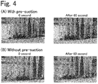
- Fig. 4 is an image diagram obtained by capturing images of tips immediately (0 second) after suction of a 70% ACN solution and 60 seconds after suction of the 70% ACN solution (A) in the case where pre-suction was performed and (B) in the case where pre-suction was not performed.
- an automatic dispensing apparatus Bravo (product of Agilent) was used as a liquid processing apparatus, and tips for 2 to 250 ⁇ L were attached to tip ends of pipettes of the apparatus.
- A representing "with pre-suction”
- 10 ⁇ L of water as a low-volatility liquid was sucked, then 3 ⁇ L of air was sucked (pre-suction), and then 2 ⁇ L of a 70% ACN solution (70% ACN/30% H 2 O v/v) was sucked.
- (B) representing "without pre-suction” 2 ⁇ L of the 70% ACN solution (70% ACN/30% H 2 O v/v) was sucked without performing pre-suction.
- Fig. 5 is a graph showing test results of peptide calibration curves by serial dilution in the cases where pre-suction is performed and where pre-suction is not performed.
- a solid line represents the case where pre-suction is performed, and a broken line represents the case where pre-suction is not performed.
- a ⁇ 1-38 peptide (2000 amol/ ⁇ L) dissolved in a 70% acetonitrile (ACN) solution was serially diluted with the 70% ACN solution. Theoretically, the concentration of A ⁇ 1-38 peptide becomes 1000 amol/ ⁇ L, 500 amol/ ⁇ L, 250 amol/ ⁇ L, 125 amol/ ⁇ L, and 62.5 amol/ ⁇ L.
- concentration of A ⁇ 1-38 peptide becomes 1000 amol/ ⁇ L, 500 amol/ ⁇ L, 250 amol/ ⁇ L, 125 amol/ ⁇ L, and 62.5 amol/ ⁇ L.
- 250 amol/ ⁇ L of stable isotope-labeled A ⁇ 1-38 peptide is dissolved as an internal standard for normalizing A ⁇ 1-38 signals measured by a mass spectrometer (MALDI-TOF MS).
- the solution diluted by each method was added dropwise 1 ⁇ L at a time to ⁇ Focus MALDI plateTM 900 ⁇ m and dried to solidify. 3 wells were dropped for each solution, and then measurement was performed by MALDI-TOF MS.
- Mass spectral data was obtained by Linear TOF in a positive ion mode using AXIMA Performance (Shimadzu/KRATOS, Manchester, UK).
- the m/z value of Linear TOF was indicated by the average mass of the peak.
- the m/z values were calibrated using human angiotensin II, human ACTH fragment 18-39, bovine insulin oxidized beta-chain, and bovine insulin as external standard.
- a signal obtained by normalizing the obtained signal of A ⁇ 1-38 with a signal of SIL-A ⁇ 1-38 was regarded as normalized intensity (Normalized intensity).
- a calibration curve was prepared using the A ⁇ 1-38 concentration and the normalized intensity, and comparison was made between the case where pre-suction was performed and the case where pre-suction was not performed. In the case where the pre-suction was not performed, the normalized intensity when the concentration was diluted by 2 times was reduced by more than a half, and linearity was not shown. In contrast, in the case where the pre-suction was performed, the normalized intensity was also reduced to half when the concentration was diluted by 2 times, and thus, linearity was shown.
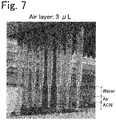
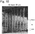
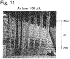
- Figs. 6 to 12 are image diagrams showing results of tests on a relationship between the amount of air suction and the liquid leakage suppressing effect in the pre-suction. These images were obtained by photographing, from obliquely below, tips attached to the lower ends of cylinders. In this test, as the pre-suction, after 10 ⁇ L of water was sucked, 2 ⁇ L ( Fig. 6 ), 3 ⁇ L ( Fig. 7 ), 5 ⁇ L ( Fig. 8 ), 10 ⁇ L ( Fig. 9 ), 50 ⁇ L ( Fig. 10 ), 100 ⁇ L ( Fig. 11 ), or 150 ⁇ L ( Fig. 12 ) of air was sucked, then 2 ⁇ L of 70% ACN solution was sucked, and then the state inside the tip was observed after the elapse of 60 seconds.
- liquid processing apparatus provided with a plurality of pipettes 2
- the processing method and the liquid processing apparatus of the present invention are not limited thereto, and can be also applied to a processing method and a liquid processing apparatus using only one pipette.
- processing method of the present invention is not only implemented in the liquid processing apparatus described in the above embodiment, but can also be implemented in the case where a liquid is processed by manually handling a pipette.
Landscapes
- Chemical & Material Sciences (AREA)
- Health & Medical Sciences (AREA)
- Analytical Chemistry (AREA)
- Chemical Kinetics & Catalysis (AREA)
- Physics & Mathematics (AREA)
- Life Sciences & Earth Sciences (AREA)
- Clinical Laboratory Science (AREA)
- Biochemistry (AREA)
- General Health & Medical Sciences (AREA)
- General Physics & Mathematics (AREA)
- Immunology (AREA)
- Pathology (AREA)
- Sampling And Sample Adjustment (AREA)
- Devices For Use In Laboratory Experiments (AREA)
Abstract
Description
- The present invention relates to a processing method for a volatile liquid using an air-replacement piston-type pipette and to a liquid processing apparatus that performs the processing method.
- Air-replacement piston-type pipettes are widely used to measure and dispense liquids in physicochemical experiments. A piston-type pipette has a structure that can move air into and out of the cylinder by moving the piston up and down in the cylinder, and by adjusting the distance to move the piston up and down, liquid can be measured accurately in a tip attached to the tip end of the cylinder, while being sucked out.
- Devices that operate piston-type pipettes electrically are also sold by various companies, and such devices are capable of continuous suction and continuous discharge. Examples of such automatic dispensing devices include Bravo available from Agilent, NIMBUS available from Affymetrix, epMotion available from Eppendorf, Microlab available from Hamilton, and Biomak available from Beckman Coulter.
- Since a piston-type pipette measures a liquid by taking in and out air, there is a problem that, while it is possible to accurately measure a liquid of a low volatility such as water, it is difficult to accurately measure a liquid of a high volatility such as acetonitrile (ACN) or acetone because liquid leakage from a suction/ejection port after suction. The reason for this is considered to be that when a highly volatile liquid is sucked through the suction/ejection port, vapor of the volatile liquid changes the internal pressure of the cylinder of the pipette or the heat of vaporization due to evaporation changes the temperature in the cylinder, and thus, air in the cylinder expands and pushes out the volatile liquid. This is also disclosed in
Non-Patent Document 1. -
- Non-Patent Document 1: The Joint Symposium of the 82nd Meeting of the Association of Organic Micro-Analysts of the Japan Society for Analytical Chemistry and the 98th Meeting of the Association of Measurement of Mechanical Quantities of the Society of Instrument and Control Engineers (the 32nd, presentation material) Theme: Dispensing operation using a micropipette
- Non-Patent Document 2: https://ocw.kyoto-u.ac.jp/ja/faculty-of-agriculture-jp/51 29000/pdf/03.pdf
- Non-Patent Document 3: https://www.aandd.co.jp/adhome/pdf/tech_doc/analytical/pi pette_guide.pdf
- As described above, when handling a volatile liquid with a pipette or the like, the liquid is volatilized at the time of suction, whereby an air layer in the tip or the cylinder expands to increase the pressure, causing a phenomenon that the liquid is pushed out. This phenomenon is called liquid leak or liquid drip. This prevents accurate measurement of the liquid.
- As a method to reduce the influence of volatilization of the volatile liquid, saturating the air layer with volatilized liquid molecules by repeatedly sucking and ejecting the liquid several times before measuring the volatile liquid is also proposed (see Non-Patent
Documents 2 and 3). However, when such a method is adopted, although it has been possible to reduce the liquid leakage rate from the suction/ejection port, it has not been possible to completely eliminate the liquid leakage. - Further, since the above method intentionally volatilizes the liquid to be measured to saturate the air layer in the cylinder, a problem is that the amount of liquid to be measured is reduced by evaporation. For example, if the liquid to be measured is present by an amount of 500 µL, even if about 2 µL volatilizes and the amount becomes 498 µL, the reduction amount is about 4%, and the influence is small. However, if only a small amount of the liquid to be measured is present, for example, 5 µL, if about 2 µL of 5 µL volatilizes to make 3 µL, the amount of liquid is reduced by about 40%, and the influence is very critical.
- Therefore, the above-mentioned method cannot be adopted when handling a very small amount such as only a few µL of volatile liquid.
- Thus, an object of the present invention is to suppress liquid leakage from a pipette due to volatilization of volatile liquid.
- A processing method according to the present invention is a processing method for a volatile liquid using a pipette including a cylinder, a piston that slides in the cylinder, and a tip attached to a tip end of the cylinder, the tip including a suction/ejection port, the pipette performing suction and ejection of a liquid through the suction/ejection port of the tip in accordance with movement of the piston. The processing method includes the following steps:
- a low-volatility liquid suction step of sucking a low-volatility liquid that is less volatile than the volatile liquid through the suction/ejection port;
- an air suction step of sucking air through the suction/ejection port after the low-volatility liquid suction step; and
- a volatile liquid suction step of sucking the volatile liquid through the suction/ejection port after the air suction step.
- A liquid processing apparatus according to the present invention is an apparatus configured to perform the processing method described above using a pipette, and includes a pipette including a vertically positioned cylinder, a piston that slides in a vertical direction in the cylinder, and a tip, the tip being attached to a lower end of the cylinder in such a way that an suction/ejection port provided at a tip end of the tip faces downward, the pipette performing suction and ejection of a liquid through the suction/ejection port of the tip in accordance with movement of the piston, a driving mechanism that causes the pipette to operate, a volatile liquid container accommodating a volatile liquid, a low-volatility liquid container accommodating a low-volatility liquid that is less volatile than the volatile liquid and a Control part that controls the driving mechanism. The Control part is configured to control the driving mechanism in such a way that a low-volatility liquid suction operation of sucking a preset amount of the low-volatility liquid from the low-volatility liquid container, an air suction operation of sucking a preset amount of air through the suction/ejection port after the low-volatility liquid suction operation, and a volatile liquid suction operation of sucking a predetermined amount of the volatile liquid from the volatile liquid container after the air suction operation are performed in a course of sucking the volatile liquid by the pipette.
- The low-volatility liquid in the present invention is a substance that has a boiling point of 95°C or higher and is in a liquid state at normal temperature (20°C ± 15°C). Examples of such a low-volatility liquid include, for example, water, dimethylsulfoxide, glycerol, phenol, and toluene.
- The volatile liquid in the present invention is a substance that has a boiling point in the range of 50 to 95°C and is in a liquid state at normal temperature (20°C. ± 15°C), or a liquid that contains 10% or more of such substance. Examples of the substance that has a boiling point in the range of 50 to 95°C and is in a liquid state at normal temperature (20°C. ± 15°C) include acetonitrile, methanol, ethanol, acetone, toluene, isopropanol, hexane, butanol, cyclohexane, ethylene glycol, benzene, chloroform, acetaldehyde, triethylamine, phenol, naphthalene, formaldehyde, tetrahydrofuran, and ethyl acetate.
- In the processing method for volatile liquid according to the present invention, since a volatile liquid is sucked after sucking a low-volatility liquid less volatile than the volatile liquid and air (hereinafter referred to as pre-suction), the volume of an air layer above the volatile liquid sucked into a pipette is smaller than in the case where the pre-suction is not performed. As a result, the volume expansion of the air layer expanding due to the volatilization of the volatile liquid is reduced, so that liquid leakage of the volatile liquid from the pipette is less likely to occur and thus, the measurement accuracy of the volatile liquid increases as compared with the case where the pre-suction is not performed.
- In the liquid processing apparatus according to the present invention, since the Control part that controls the driving mechanism that drives the pipette is configured to perform suction of the volatile liquid after performing the above-described pre-suction in the process of sucking the volatile liquid by the pipette, liquid leakage of the volatile liquid from the pipette is less likely to occur, and the measurement accuracy of the volatile liquid is improved.
-
-
Fig. 1 is a schematic configuration diagram illustrating an embodiment of a liquid processing apparatus. -
Fig. 2 is a flowchart showing an example of a series of operations at the time of liquid suction according to the same embodiment. -
Fig. 3 schematically illustrates states inside a tip after liquid suction according to the same embodiment. -
Fig. 4 is an image diagram for comparing the remaining amount of liquid in the tip between the cases where pre-suction is performed and where pre-suction is not performed, (A) represents the case where the pre-suction is performed, and (B) represents the case where the pre-suction is not performed. -
Fig. 5 is a graph showing peptide calibration curves by serial dilution in the cases where pre-suction is performed and where pre-suction is not performed. -
Fig. 6 is an image diagram showing the remaining amount of liquid in the tip when pre-suction is performed with an air layer volume of 2 µL. -
Fig. 7 is an image diagram showing the remaining amount of liquid in the tip when pre-suction is performed with an air layer volume of 3 µL. -
Fig. 8 is an image diagram showing the remaining amount of liquid in the tip when pre-suction is performed with an air layer volume of 5 µL. -
Fig. 9 is an image diagram showing the remaining amount of liquid in the tip when pre-suction is performed with an air layer volume of 10 µL. -
Fig. 10 is an image diagram showing the remaining amount of liquid in the tip when pre-suction is performed with an air layer volume of 50 µL. -
Fig. 11 is an image diagram showing the remaining amount of liquid in the tip when pre-suction is performed with an air layer volume of 100 µL. -
Fig. 12 is an image diagram showing the remaining amount of liquid in the tip when pre-suction is performed with an air layer volume of 150 µL. - Hereinafter, an embodiment of a processing method for a volatile liquid and a liquid processing apparatus that performs the processing method according to the present invention will be described with reference to the drawings.
- First, an embodiment of the liquid processing apparatus will be described with reference to
Fig. 1 . - In the liquid processing apparatus of this embodiment, a plurality of
pipettes 2 are held by aholder 10 in state of being arranged in a line. Thepipette 2 includes acylinder 4 disposed vertically, apiston 6 that slides in the vertical direction in thecylinder 4, and atip 8 attached to a lower end of thecylinder 4. Thetip 8 has a suction/ejection port at a tip end thereof, and the suction/ejection port faces vertically downward. - Each
pipette 2 is configured to suck liquid or gas through the suction/ejection portion of thetip 8 in accordance with upward movement of thepiston 4, and eject liquid or gas through the suction/ejection portion of thetip 8 in accordance with downward movement of thepiston 4. In addition, thepipette 2 is configured to move in the horizontal in-plane direction and in the vertical direction, and suck and eject a liquid from and to a desired container. In this embodiment, all thepipettes 2 are held by thecommon holder 10, and by moving theholder 10 in the horizontal in-plane direction and in the vertical direction, eachpipette 2 moves in the horizontal in-plane direction and in the vertical direction. - A
driving mechanism 12 includes a mechanism for moving thepiston 4 and a mechanism for moving theholder 10. The operation of thedriving mechanism 12 is controlled by theControl part 14. AControl part 14 is realized by a general-purpose personal computer or a dedicated computer. - A plurality of volatile
liquid containers 16 accommodating volatile liquids and a plurality of low-volatility liquid containers 18 accommodating low-volatility liquids are provided at positions lower than thepipettes 2 in correspondence with therespective pipettes 2. - Examples of the volatile liquids accommodated in the volatile
liquid containers 16 include liquids such as acetonitrile, methanol, ethanol, acetone, toluene, isopropanol, hexane, butanol, cyclohexane, ethylene glycol, benzene, chloroform, acetaldehyde, triethylamine, phenol, naphthalene, formaldehyde, tetrahydrofuran, and ethyl acetate, and liquids containing 10% or more of such liquids. - Examples of the low-volatility liquids accommodated in the low-
volatility liquid containers 18 include water, dimethylsulfoxide, glycerol, phenol, and toluene. The low-volatility liquids contained in the low-volatility liquid containers 18 are used when measuring off the above-mentioned volatile liquids, while sucking them out by thepipettes 2. - The
Control part 14 is configured to control thedriving mechanism 12 so that the following operation is performed when the liquid is sucked. A series of operations for sucking liquid will be described with reference to the flowchart ofFig. 2 withFig. 1 - When the liquid suction operation is started, first, it is checked whether or not the liquid to be sucked is a volatile liquid. In order to check whether or not the liquid is a volatile liquid, for example, a list of volatile liquids is stored in a storage area of a data memory or the like provided in the
Control part 14, and whether or not the liquid to be sucked is a volatile liquid is determined by comparing the liquid to be sucked with the list. - If the liquid to be sucked is not a volatile liquid, the liquid is sucked by a predetermined amount through the suction/ejection port at the tip end of each
pipette 2. As a result of this, a predetermined amount of the liquid to be sucked is measured in thetip 8 attached to the tip end of eachpipette 2. The liquid measured in eachtip 8 is then dispensed into a predetermined dispensing container. - In contrast, in the case where the liquid to be sucked is a volatile liquid, a low-volatility liquid suction operation is performed first. In the low-volatility liquid suction operation, the
pipette 2 is moved to the position of the corresponding low-volatility liquid container 18 to insert the tip end of eachtip 8 into the low-volatility liquid container 18, and from each low-volatility liquid container 18, a preset amount of low-volatility liquid is sucked. - After the low-volatility liquid suction operation is completed, an air suction operation is performed. In the air suction operation, in a state where the
tip 8 at the tip end of eachpipette 2 is pulled out from the low-volatility liquid container 18, eachpipette 2 is driven to suck, and eachpipette 2 is thus caused to suck a preset amount of air. As a result, an air layer is formed below a low-volatility liquid layer in thepipette 2. Hereinafter, the low-volatility liquid suction operation and the air suction operation will be collectively referred to as "pre-suction". - After the above-mentioned pre-suction, the volatile liquid suction operation is performed. In the volatile liquid suction operation, the
pipette 2 is moved to the position of the volatileliquid container 16 accommodating the volatile liquid to be sucked, and a predetermined amount of volatile liquid is sucked from each volatileliquid container 16. - By sequentially performing the low-volatility liquid suction operation, the air suction operation, and the volatile liquid suction operation as described above, that is, by performing the pre-suction before the volatile liquid suction operation, a layer of low-volatility liquid, an air layer, and a layer of a volatile liquid are formed in the
tip 8 of thepipette 2 in this order from the proximal end side of thetip 8 as illustrated inFig. 3(A) . - When the volatile liquid is sucked from the tip end of the
tip 8 without performing the above-mentioned pre-suction, an air layer of a huge volume is generated between the volatile liquid and thepiston 6 as illustrated inFig. 3(B) . If the volume of the air layer between the volatile liquid and thepiston 6 is large, the volatilization of the volatile liquid causes the air layer to greatly expand, thereby pushing out the volatile liquid to cause liquid leakage. - In this embodiment, by performing the pre-suction before the volatile liquid suction operation, the volume of the air layer that can be expanded by volatilization of the volatile liquid becomes smaller than in the case where the pre-suction is not performed, therefore the expansion volume of the air layer due to the effect of volatilization also decreases, and liquid leakage from the tip end of the
tip 8 becomes less likely to occur. -
Fig. 4 is an image diagram obtained by capturing images of tips immediately (0 second) after suction of a 70% ACN solution and 60 seconds after suction of the 70% ACN solution (A) in the case where pre-suction was performed and (B) in the case where pre-suction was not performed. - In this test, an automatic dispensing apparatus Bravo (product of Agilent) was used as a liquid processing apparatus, and tips for 2 to 250 µL were attached to tip ends of pipettes of the apparatus. In (A) representing "with pre-suction", first, 10 µL of water as a low-volatility liquid was sucked, then 3 µL of air was sucked (pre-suction), and then 2 µL of a 70% ACN solution (70% ACN/30% H2O v/v) was sucked. In (B) representing "without pre-suction", 2 µL of the 70% ACN solution (70% ACN/30% H2O v/v) was sucked without performing pre-suction.
- As a result of this test, both in the case of "with pre-suction" and in the case of "without pre-suction", 70% ACN solution of about the same amount exists at the tip ends of the tips immediately (0 second) after suction of the 70% ACN solution. However, after 60 seconds have passed (60 seconds later) since the 70% ACN solution was sucked, the amount of the 70% ACN solution at the tip ends of the tips was hardly reduced and no liquid leakage from the tip ends of the tips was observed in the case of "with pre-suction", and the amount of the 70% ACN solution at the tip ends of the tips was significantly reduced and liquid leakage from the tip ends of the tips was observed in the case of "without pre-suction". Therefore, it was confirmed from this test result that the liquid leakage from the tip end of the tip can be suppressed by performing the pre-suction.
-
Fig. 5 is a graph showing test results of peptide calibration curves by serial dilution in the cases where pre-suction is performed and where pre-suction is not performed. A solid line represents the case where pre-suction is performed, and a broken line represents the case where pre-suction is not performed. - In this test, Aβ1-38 peptide (2000 amol/µL) dissolved in a 70% acetonitrile (ACN) solution was serially diluted with the 70% ACN solution. Theoretically, the concentration of Aβ1-38 peptide becomes 1000 amol/µL, 500 amol/µL, 250 amol/µL, 125 amol/µL, and 62.5 amol/µL. In the 70% ACN solution, 250 amol/µL of stable isotope-labeled Aβ1-38 peptide (SIL-Aβ1-38) is dissolved as an internal standard for normalizing Aβ1-38 signals measured by a mass spectrometer (MALDI-TOF MS). The solution diluted by each method was added dropwise 1 µL at a time to µFocus MALDI plate™ 900 µm and dried to solidify. 3 wells were dropped for each solution, and then measurement was performed by MALDI-TOF MS.
- Mass spectral data was obtained by Linear TOF in a positive ion mode using AXIMA Performance (Shimadzu/KRATOS, Manchester, UK). The m/z value of Linear TOF was indicated by the average mass of the peak. The m/z values were calibrated using human angiotensin II, human ACTH fragment 18-39, bovine insulin oxidized beta-chain, and bovine insulin as external standard.
- A signal obtained by normalizing the obtained signal of Aβ1-38 with a signal of SIL-Aβ1-38 was regarded as normalized intensity (Normalized intensity). A calibration curve was prepared using the Aβ 1-38 concentration and the normalized intensity, and comparison was made between the case where pre-suction was performed and the case where pre-suction was not performed. In the case where the pre-suction was not performed, the normalized intensity when the concentration was diluted by 2 times was reduced by more than a half, and linearity was not shown. In contrast, in the case where the pre-suction was performed, the normalized intensity was also reduced to half when the concentration was diluted by 2 times, and thus, linearity was shown. Since the coefficient of determination (R2) in the linear regression equation was R2 = 0.9718 for the conventional method and R2 = 0.9993 for the case where the pre-suction was performed, it was shown that linear fitting can be performed by performing the pre-suction. These results show that only an amount smaller than an intended amount was injected due to liquid leakage in the case where the pre-suction was not performed, and the liquid leakage was suppressed and a liquid of about the same amount as the intended amount was accurately injected in the case where the pre-suction was performed.
- The results described above show that, by performing the pre-suction, liquid leakage from the tip ends of the
pipettes 2 can be suppressed, and the measurement accuracy of the volatile liquid can be improved. -
Figs. 6 to 12 are image diagrams showing results of tests on a relationship between the amount of air suction and the liquid leakage suppressing effect in the pre-suction. These images were obtained by photographing, from obliquely below, tips attached to the lower ends of cylinders. In this test, as the pre-suction, after 10 µL of water was sucked, 2 µL (Fig. 6 ), 3 µL (Fig. 7 ), 5 µL (Fig. 8 ), 10 µL (Fig. 9 ), 50 µL (Fig. 10 ), 100 µL (Fig. 11 ), or 150 µL (Fig. 12 ) of air was sucked, then 2 µL of 70% ACN solution was sucked, and then the state inside the tip was observed after the elapse of 60 seconds. - As a result of this test, it was found that, in the case where the amount of air suction was 10 µL or less, almost no reduction was observed in the amount of 70% ACN solution in the tip even after the elapse of 60 seconds after suction, and liquid leakage was suppressed. However, in the case where the amount of air suction was 50 µL or 100 µL, it was found that reduction of the amount of the 70% ACN solution in the tip was observed 60 seconds after the suction, and liquid leakage occurred.
- From this test, it was confirmed that, although it is possible to suppress the liquid leakage of the volatile liquid by performing the pre-suction, the volume of expansion due to the influence of the volatilization of the volatile liquid becomes greater, and the effect of suppressing liquid leakage is degraded in the case where the volume of the air layer between the low-volatility liquid and the volatile liquid is larger. Under the conditions used in this test, it was confirmed that, if the amount of air suction is 10 µL or less, the amount of reduction of the volatile liquid can be suppressed within 10% of the amount of suction, and a sufficient liquid leakage suppression effect can be achieved. The amount of air suction in the pre-suction can be adjusted to an appropriate amount in accordance with the volatility and the amount of suction of the volatile liquid.
- Although a liquid processing apparatus provided with a plurality of
pipettes 2 is described above as an example, the processing method and the liquid processing apparatus of the present invention are not limited thereto, and can be also applied to a processing method and a liquid processing apparatus using only one pipette. - Further, the processing method of the present invention is not only implemented in the liquid processing apparatus described in the above embodiment, but can also be implemented in the case where a liquid is processed by manually handling a pipette.
-
- 2: Pipette
- 4: Cylinder
- 6: Piston
- 8: Tip
- 10: Holder
- 12: Driving mechanism
- 14: Control part
- 16: Volatile liquid Container
- 18: Low-volatility liquid container
Claims (6)
- A processing method for a volatile liquid using a pipette including a cylinder, a piston that slides in the cylinder, and a tip attached to a tip end of the cylinder, the tip including a suction/ejection port, the pipette performing suction and ejection of a liquid through the suction/ejection port of the tip in accordance with movement of the piston, the processing method comprising:a low-volatility liquid suction step of sucking a low-volatility liquid that is less volatile than the volatile liquid through the suction/ejection port;an air suction step of sucking air through the suction/ejection port after the low-volatility liquid suction step; anda volatile liquid suction step of sucking the volatile liquid through the suction/ejection port after the air suction step.
- The processing method according to claim 1, wherein the low-volatility liquid is any one of water, dimethyl sulfoxide, glycerol, phenol, and toluene.
- The processing method according to claim 1 or 2, wherein the volatile liquid is any one of acetonitrile, methanol, ethanol, acetone, toluene, isopropanol, hexane, butanol, cyclohexane, ethylene glycol, benzene, chloroform, acetaldehyde, triethylamine, phenol, naphthalene, formaldehyde, tetrahydrofuran, and ethyl acetate, or a liquid containing 10% or more of these.
- A liquid processing apparatus comprising:a pipette including a vertically positioned cylinder, a piston that slides in a vertical direction in the cylinder, and a tip, the tip being attached to a lower end of the cylinder in such a way that an suction/ejection port provided at a tip end of the tip faces downward, the pipette performing suction and ejection of a liquid through the suction/ejection port of the tip in accordance with movement of the piston;a driving mechanism that causes the pipette to operate;a volatile liquid container accommodating a volatile liquid;a low-volatility liquid container accommodating a low-volatility liquid that is less volatile than the volatile liquid; anda Control part that controls the driving mechanism,wherein the Control part is configured to control the driving mechanism in such a way that a low-volatility liquid suction operation of sucking a preset amount of the low-volatility liquid from the low-volatility liquid container, an air suction operation of sucking a preset amount of air through the suction/ejection port after the low-volatility liquid suction operation, and a volatile liquid suction operation of sucking a predetermined amount of the volatile liquid from the volatile liquid container after the air suction operation are performed in a course of sucking the volatile liquid by the pipette.
- The liquid processing apparatus according to claim 4, wherein the low-volatility liquid is any one of water, dimethyl sulfoxide, glycerol, phenol, and toluene.
- The liquid processing apparatus according to claim 4 or 5, wherein the volatile liquid is any one of acetonitrile, methanol, ethanol, acetone, toluene, isopropanol, hexane, butanol, cyclohexane, ethylene glycol, benzene, chloroform, acetaldehyde, triethylamine, phenol, naphthalene, formaldehyde, tetrahydrofuran, and ethyl acetate, or a liquid containing 10% or more of these.
Applications Claiming Priority (2)
| Application Number | Priority Date | Filing Date | Title |
|---|---|---|---|
| JP2017012011 | 2017-01-26 | ||
| PCT/JP2017/046065 WO2018139132A1 (en) | 2017-01-26 | 2017-12-22 | Method for treating volatile liquid and device for treating liquid |
Publications (2)
| Publication Number | Publication Date |
|---|---|
| EP3575770A1 true EP3575770A1 (en) | 2019-12-04 |
| EP3575770A4 EP3575770A4 (en) | 2020-06-17 |
Family
ID=62978477
Family Applications (1)
| Application Number | Title | Priority Date | Filing Date |
|---|---|---|---|
| EP17893536.7A Pending EP3575770A4 (en) | 2017-01-26 | 2017-12-22 | VOLATILE LIQUID TREATMENT METHOD AND LIQUID TREATMENT DEVICE |
Country Status (7)
| Country | Link |
|---|---|
| US (1) | US11471875B2 (en) |
| EP (1) | EP3575770A4 (en) |
| JP (3) | JPWO2018139132A1 (en) |
| CN (1) | CN110168342B (en) |
| AU (2) | AU2017396218A1 (en) |
| SG (1) | SG10202109794XA (en) |
| WO (1) | WO2018139132A1 (en) |
Families Citing this family (2)
| Publication number | Priority date | Publication date | Assignee | Title |
|---|---|---|---|---|
| WO2021174044A1 (en) * | 2020-02-28 | 2021-09-02 | Perkinelmer Health Sciences, Inc. | Multiplexed polymerase chain reaction in micropipette format |
| CN115041246B (en) * | 2022-07-15 | 2023-04-18 | 成都瀚辰光翼科技有限责任公司 | Pipette control method and device, pipette control device, and readable storage medium |
Family Cites Families (19)
| Publication number | Priority date | Publication date | Assignee | Title |
|---|---|---|---|---|
| JPS5631650A (en) * | 1979-08-24 | 1981-03-31 | Hitachi Ltd | Partial injection unit of solution |
| JPS62144073A (en) | 1985-12-18 | 1987-06-27 | Hitachi Ltd | Dispensing device |
| JPS62228952A (en) | 1986-03-31 | 1987-10-07 | Toshiba Corp | Suction discharge method for automatic chemical analyzer |
| JPH0316648A (en) * | 1989-06-14 | 1991-01-24 | Hitachi Ltd | Dispenser |
| JPH04329364A (en) * | 1991-05-02 | 1992-11-18 | Olympus Optical Co Ltd | Sample separate injecting method |
| US5312757A (en) | 1991-05-02 | 1994-05-17 | Olympus Optical Co., Ltd. | Sample distributing method |
| JP3152675B2 (en) * | 1991-05-02 | 2001-04-03 | オリンパス光学工業株式会社 | Dispensing method |
| JPH04329365A (en) * | 1991-05-02 | 1992-11-18 | Olympus Optical Co Ltd | Sample separate injecting method |
| JP2939180B2 (en) * | 1996-04-19 | 1999-08-25 | 株式会社大日本精機 | Liquid dispensing method and device |
| JP3410306B2 (en) * | 1996-10-21 | 2003-05-26 | アロカ株式会社 | Sample suction method and sample suction control device |
| US6734424B2 (en) * | 2002-05-16 | 2004-05-11 | Large Scale Proteomics Corporation | Method for microdispensing of fluids from a pipette |
| US8293521B2 (en) * | 2005-03-30 | 2012-10-23 | Shimadzu Corporation | Method of dispensing nonvolatile liquid in reaction vessel and reaction vessel processing apparatus |
| EP1745851B1 (en) * | 2005-07-22 | 2015-02-25 | Tecan Trading AG | Process, device and computerprogramm product for the classification of a liquid |
| DE102006046542A1 (en) * | 2006-09-27 | 2008-04-03 | Weber, Jürgen | Pipette with pipette holder for reception of volatile liquids, comprises an inserted closing element, which locks the pipette tip after filling, so that the pipette is transferred in drip-free manner |
| DE202006015057U1 (en) * | 2006-09-27 | 2006-12-07 | Weber, Jürgen | Pipette and holder are used to transfer volatile liquids to test tubes, pipette having ground surface on inside of its nozzle which is closed by conical ground glass stopper and pipette holder allowing it to be emptied in one or more stages |
| JP5187286B2 (en) | 2009-07-17 | 2013-04-24 | コニカミノルタビジネステクノロジーズ株式会社 | Image forming apparatus |
| JP2011224439A (en) * | 2010-04-16 | 2011-11-10 | Seiko Epson Corp | Pipet device |
| AU2011320358B2 (en) * | 2010-10-29 | 2015-09-03 | Thermo Fisher Scientific Oy | Automated system for sample preparation and analysis |
| CN205462311U (en) * | 2016-04-07 | 2016-08-17 | 四川农业大学 | Liquid moving device |
-
2017
- 2017-12-22 JP JP2018564171A patent/JPWO2018139132A1/en active Pending
- 2017-12-22 AU AU2017396218A patent/AU2017396218A1/en not_active Abandoned
- 2017-12-22 SG SG10202109794X patent/SG10202109794XA/en unknown
- 2017-12-22 WO PCT/JP2017/046065 patent/WO2018139132A1/en not_active Ceased
- 2017-12-22 EP EP17893536.7A patent/EP3575770A4/en active Pending
- 2017-12-22 US US16/480,528 patent/US11471875B2/en active Active
- 2017-12-22 CN CN201780082947.3A patent/CN110168342B/en active Active
-
2021
- 2021-02-02 AU AU2021200667A patent/AU2021200667B2/en active Active
- 2021-06-15 JP JP2021099604A patent/JP7504059B2/en active Active
-
2023
- 2023-06-26 JP JP2023103924A patent/JP2023134511A/en not_active Withdrawn
Also Published As
| Publication number | Publication date |
|---|---|
| SG10202109794XA (en) | 2021-10-28 |
| EP3575770A4 (en) | 2020-06-17 |
| JPWO2018139132A1 (en) | 2019-11-07 |
| US20190376995A1 (en) | 2019-12-12 |
| CN110168342B (en) | 2025-11-04 |
| JP2023134511A (en) | 2023-09-27 |
| AU2017396218A1 (en) | 2019-07-18 |
| WO2018139132A1 (en) | 2018-08-02 |
| AU2021200667B2 (en) | 2022-12-01 |
| JP7504059B2 (en) | 2024-06-21 |
| JP2021154287A (en) | 2021-10-07 |
| AU2021200667A1 (en) | 2021-03-04 |
| CN110168342A (en) | 2019-08-23 |
| US11471875B2 (en) | 2022-10-18 |
Similar Documents
| Publication | Publication Date | Title |
|---|---|---|
| AU2021200667B2 (en) | Method for treating volatile liquid and device for treating liquid | |
| Lozano et al. | Pushing the analytical limits: new insights into complex mixtures using mass spectra segments of constant ultrahigh resolving power | |
| Zhong et al. | Characterizing the resolution and accuracy of a second-generation traveling-wave ion mobility separator for biomolecular ions | |
| US10204776B1 (en) | Tuning multipole RF amplitude for ions not present in calibrant | |
| US8101908B2 (en) | Multi-resolution scan | |
| Rioseras et al. | Secondary electrospray ionization proceeds via gas-phase chemical ionization | |
| US9322814B2 (en) | Mass spectrometer | |
| GB2575726A (en) | Bench-top time of flight mass spectrometer | |
| EP2299471A1 (en) | Quadrupole mass analyzer | |
| US20200103373A1 (en) | Determining the reduced ion mobility of ion species by trapped ion mobility spectrometry (tims) | |
| US9299545B2 (en) | Systems and methods for calibrating mass spectrometers | |
| US12334327B2 (en) | Mass spectrometry device control method, mass spectrometry system, and voltage control device | |
| JP7523527B2 (en) | Methods for Mass Spectrometry | |
| US20220074901A1 (en) | Liquid chromatograph mass spectrometer | |
| US9484192B2 (en) | Data directed storage of imaging mass spectra | |
| WO2020110864A1 (en) | Analysis method and program | |
| US20240077462A1 (en) | Accurate chromatography-mass spectral analysis of mixtures | |
| CN116868305A (en) | Electrode protrusion adjusted to maximize pressure drop across fluid transport conduit | |
| JP7527350B2 (en) | Methods for Mass Spectrometry | |
| US8183525B2 (en) | Method and system for analysing a dose formulation of a metered dose device | |
| JP7652942B2 (en) | How to calibrate a mass spectrometer | |
| JP7364377B2 (en) | Explosives inspection equipment | |
| Musselman et al. | Enabling automated sample analysis by direct analysis in real time (DART) mass spectrometry | |
| GB2517007A (en) | Data directed storage of imaging mass spectra | |
| JP2021096254A (en) | Automated method for maintaining and managing clinical diagnostics system |
Legal Events
| Date | Code | Title | Description |
|---|---|---|---|
| STAA | Information on the status of an ep patent application or granted ep patent |
Free format text: STATUS: THE INTERNATIONAL PUBLICATION HAS BEEN MADE |
|
| PUAI | Public reference made under article 153(3) epc to a published international application that has entered the european phase |
Free format text: ORIGINAL CODE: 0009012 |
|
| STAA | Information on the status of an ep patent application or granted ep patent |
Free format text: STATUS: REQUEST FOR EXAMINATION WAS MADE |
|
| 17P | Request for examination filed |
Effective date: 20190801 |
|
| AK | Designated contracting states |
Kind code of ref document: A1 Designated state(s): AL AT BE BG CH CY CZ DE DK EE ES FI FR GB GR HR HU IE IS IT LI LT LU LV MC MK MT NL NO PL PT RO RS SE SI SK SM TR |
|
| AX | Request for extension of the european patent |
Extension state: BA ME |
|
| DAV | Request for validation of the european patent (deleted) | ||
| DAX | Request for extension of the european patent (deleted) | ||
| A4 | Supplementary search report drawn up and despatched |
Effective date: 20200518 |
|
| RIC1 | Information provided on ipc code assigned before grant |
Ipc: B01L 3/02 20060101ALI20200512BHEP Ipc: G01N 1/00 20060101AFI20200512BHEP Ipc: G01N 35/10 20060101ALI20200512BHEP |
|
| STAA | Information on the status of an ep patent application or granted ep patent |
Free format text: STATUS: EXAMINATION IS IN PROGRESS |
|
| 17Q | First examination report despatched |
Effective date: 20210317 |