EP3575706B1 - Absorberbeschichtung für solarthermische energieerzeugung und herstellungsverfahren dafür - Google Patents
Absorberbeschichtung für solarthermische energieerzeugung und herstellungsverfahren dafür Download PDFInfo
- Publication number
- EP3575706B1 EP3575706B1 EP17893530.0A EP17893530A EP3575706B1 EP 3575706 B1 EP3575706 B1 EP 3575706B1 EP 17893530 A EP17893530 A EP 17893530A EP 3575706 B1 EP3575706 B1 EP 3575706B1
- Authority
- EP
- European Patent Office
- Prior art keywords
- coating
- power generation
- absorber
- solar heat
- heat power
- Prior art date
- Legal status (The legal status is an assumption and is not a legal conclusion. Google has not performed a legal analysis and makes no representation as to the accuracy of the status listed.)
- Active
Links
Images










Classifications
-
- F—MECHANICAL ENGINEERING; LIGHTING; HEATING; WEAPONS; BLASTING
- F24—HEATING; RANGES; VENTILATING
- F24S—SOLAR HEAT COLLECTORS; SOLAR HEAT SYSTEMS
- F24S70/00—Details of absorbing elements
- F24S70/20—Details of absorbing elements characterised by absorbing coatings; characterised by surface treatment for increasing absorption
- F24S70/25—Coatings made of metallic material
-
- C—CHEMISTRY; METALLURGY
- C01—INORGANIC CHEMISTRY
- C01G—COMPOUNDS CONTAINING METALS NOT COVERED BY SUBCLASSES C01D OR C01F
- C01G37/00—Compounds of chromium
-
- C—CHEMISTRY; METALLURGY
- C01—INORGANIC CHEMISTRY
- C01G—COMPOUNDS CONTAINING METALS NOT COVERED BY SUBCLASSES C01D OR C01F
- C01G45/00—Compounds of manganese
-
- C—CHEMISTRY; METALLURGY
- C01—INORGANIC CHEMISTRY
- C01G—COMPOUNDS CONTAINING METALS NOT COVERED BY SUBCLASSES C01D OR C01F
- C01G49/00—Compounds of iron
-
- C—CHEMISTRY; METALLURGY
- C01—INORGANIC CHEMISTRY
- C01G—COMPOUNDS CONTAINING METALS NOT COVERED BY SUBCLASSES C01D OR C01F
- C01G51/00—Compounds of cobalt
-
- C—CHEMISTRY; METALLURGY
- C09—DYES; PAINTS; POLISHES; NATURAL RESINS; ADHESIVES; COMPOSITIONS NOT OTHERWISE PROVIDED FOR; APPLICATIONS OF MATERIALS NOT OTHERWISE PROVIDED FOR
- C09K—MATERIALS FOR MISCELLANEOUS APPLICATIONS, NOT PROVIDED FOR ELSEWHERE
- C09K5/00—Heat-transfer, heat-exchange or heat-storage materials, e.g. refrigerants; Materials for the production of heat or cold by chemical reactions other than by combustion
- C09K5/08—Materials not undergoing a change of physical state when used
- C09K5/14—Solid materials, e.g. powdery or granular
-
- F—MECHANICAL ENGINEERING; LIGHTING; HEATING; WEAPONS; BLASTING
- F24—HEATING; RANGES; VENTILATING
- F24S—SOLAR HEAT COLLECTORS; SOLAR HEAT SYSTEMS
- F24S70/00—Details of absorbing elements
- F24S70/20—Details of absorbing elements characterised by absorbing coatings; characterised by surface treatment for increasing absorption
-
- F—MECHANICAL ENGINEERING; LIGHTING; HEATING; WEAPONS; BLASTING
- F24—HEATING; RANGES; VENTILATING
- F24S—SOLAR HEAT COLLECTORS; SOLAR HEAT SYSTEMS
- F24S70/00—Details of absorbing elements
- F24S70/20—Details of absorbing elements characterised by absorbing coatings; characterised by surface treatment for increasing absorption
- F24S70/225—Details of absorbing elements characterised by absorbing coatings; characterised by surface treatment for increasing absorption for spectrally selective absorption
-
- F—MECHANICAL ENGINEERING; LIGHTING; HEATING; WEAPONS; BLASTING
- F24—HEATING; RANGES; VENTILATING
- F24S—SOLAR HEAT COLLECTORS; SOLAR HEAT SYSTEMS
- F24S70/00—Details of absorbing elements
- F24S70/30—Auxiliary coatings, e.g. anti-reflective coatings
-
- Y—GENERAL TAGGING OF NEW TECHNOLOGICAL DEVELOPMENTS; GENERAL TAGGING OF CROSS-SECTIONAL TECHNOLOGIES SPANNING OVER SEVERAL SECTIONS OF THE IPC; TECHNICAL SUBJECTS COVERED BY FORMER USPC CROSS-REFERENCE ART COLLECTIONS [XRACs] AND DIGESTS
- Y02—TECHNOLOGIES OR APPLICATIONS FOR MITIGATION OR ADAPTATION AGAINST CLIMATE CHANGE
- Y02E—REDUCTION OF GREENHOUSE GAS [GHG] EMISSIONS, RELATED TO ENERGY GENERATION, TRANSMISSION OR DISTRIBUTION
- Y02E10/00—Energy generation through renewable energy sources
- Y02E10/40—Solar thermal energy, e.g. solar towers
Definitions
- the present invention relates to a heat absorber coating usable for solar heat power generation (also referred to as “concentration solar power generation”) and a manufacturing method thereof.
- Solar photovoltaic generation and solar heat power generation are known as a method of generating electricity using sunlight, a representative natural energy.
- Solar photovoltaic generation is a system that converts sunlight directly into electric power, and is now in practical use all over the world.
- solar heat power generation is a method of collecting sunlight and using it as a heat source to generate electricity by turning a turbine. In the case of converting sunlight into heat, solar energy can be converted with higher efficiency than when converting sunlight directly into electricity, which has been brought to attention in recent years (see, for example, Patent Literature 1).
- a coating containing chromium nitride is used as a heat absorber coating used for a heat collector of solar heat power generation, but there is concern that chromium nitride imposes a large environmental burden. Therefore, a titanium oxynitride thin coating having a property of absorbing visible light has been proposed (see, for example, Patent Literature 2).
- a titanium oxynitride thin coating having a property of absorbing visible light has been proposed (see, for example, Patent Literature 2).
- carbon is added to titanium oxynitride to improve the visible spectral absorptance (see, for example, Patent Literature 3).
- the present inventor invented a coating containing titanium oxide and carbon nanotubes and successfully developed a heat absorber coating having higher practical utility than before (refer to Patent Literature 4).
- a central tube for linear concentrating solar thermal power plants having an absorber layer is described in Patent Literature 5.
- the absorber layer is generated by cold gas sputtering.
- titanium oxynitride can absorb visible light.
- the addition of carbon in addition to the visible light absorption of titanium oxynitride, the addition of carbon can improve visible spectral absorptance and infrared light radiation. However, it is desired to efficiently collect heat by further improving the spectral absorptance of the coatings.
- the heat absorber coating developed by the present inventor that is, the coating obtained by adding carbon nanotubes to titanium oxide has superior characteristics to the conventional one.
- carbon may be oxidized and consumed at a high temperature, and in order to promote practical application of solar heat power generation, a coating excellent in thermal oxidation resistance that can be used at a higher temperature is desired.
- An object of the present invention is to provide a heat absorber coating for solar heat power generation having excellent thermal oxidation resistance and high spectral absorptance and a method of manufacturing the same.
- a coating suitable for solar receiver in solar heat power generation can be obtained by coating titanium oxide on the inside and outside of a porous structure (also referred to as a three-dimensional coating, or 3-D coating) in which particles of a metal oxide having a higher thermal oxidation resistance than a carbon nanotube are partially joined to each other, and finally completed the present invention.
- a porous structure also referred to as a three-dimensional coating, or 3-D coating
- the object of the present invention was achieved by the following means.
- an absorber coating for solar heat power generation which has excellent thermal oxidation resistance and high spectral absorptance.
- the absorber coating for solar heat power generation has a network structure of composite particles comprising metal oxide particles and titanium oxide partially or entirely covering the surface of the particles.
- the absorber coating for solar heat power generation preferably has a porous silica coating on its outermost surface. Note that the absorber coating for solar heat power generation may contain a material other than the metal oxide particles, titanium oxide covering the surface thereof, and porous silica coating on the outermost surface of the absorber coating for solar heat power generation.
- Particles of metal oxide forming the absorber coating for solar heat power generation preferably have an average particle size in the range of 0.5 to 5 ⁇ m.
- the particle size including the average particle diameter is measured by laser diffraction scattering method.
- the metal oxide is a metal oxide particle mainly containing two or more metals selected from Mn, Cr, Cu, Zr, Mo, Fe, Co and Bi.
- Preferred metal oxides include:
- the metal oxide may be a mixed oxide of a plurality of simple metal oxides, or may be a composite oxide in which plural kinds of metals constitute oxides.
- a composite oxide having a spinel structure can be suitably exemplified.
- metal oxides those containing mainly two or more metals from Cr, Mn and Cu are particularly preferable.
- Titanium oxide has a form of coating covering the particle surface of the metal oxide.
- the titanium oxide may cover the entire surface of the particle or cover a part of the surface of the particle.
- the metal oxide particles form the skeleton of the absorber coating for solar heat power generation, and constitute a three-dimensional network-like porous body. Titanium oxide may sometimes be present at the junction between the particles, but sometimes it is not interposed.
- the titanium oxide preferably has an anatase type crystal structure when it is not used as a part of the collector for solar heat power generation. However, since it is exposed to high temperatures when used as a condenser, it can be converted to a rutile type crystal structure. Note that the titanium oxide coating may have a rutile type crystal structure from the beginning.
- the porous silica coating is a coating that covers an outermost surface of the absorber coating for solar heat power generation.
- the coating must be resistant to the thermal expansion when the absorber coating for solar heat power generation and the substrate on which the coating is formed thermally expand. The reason why the porous silica coating is formed is to prevent the collapse of the porous three-dimensional coating and to make it resistant to thermal expansion.
- the absorber coating for solar heat power generation is a coating formed on a substrate and is a porous coating (may be called a three-dimensional coating) that has many pores (whether open pores or closed pores).
- a metal material having a high thermal conductivity such as a steel sheet, a copper sheet, an aluminum sheet, an aluminum-plated steel sheet, an aluminum alloy plated steel sheet, a copper-plated steel sheet, a tin-plated steel sheet, a chromium plated steel sheet, a stainless-steel sheet or a nickel-base superalloy.
- the absorber coating for solar heat power generation preferably has a large number of pores so that a surface area thereof is seven times or more, more preferably eight times or more to the projected area of its surface.
- the surface roughness of the absorber coating for solar heat power generation is 1.0 ⁇ m or more in arithmetic average roughness (Ra). Further, the maximum height (Rz) of the surface of the absorber coating for solar heat power generation is preferably 14 ⁇ m or more, more preferably 16 ⁇ m or more.
- Ra is preferably 1.0 ⁇ m or more.
- projected area means the area of a certain measurement area (microscopic field of view) as viewed in a direction perpendicular to the surface of the substrate (thickness direction of the substrate). "The surface area to the projected area is seven times of more” means that the actual surface area in the measurement area is seven times or more to the projected area of the measurement area. "Surface area to the projected area”, “Ra” and “Rz” can be values measured using a shape measuring laser microscope.
- the porous coating obtained by coating a metal oxide particle network with a titanium oxide coating may be formed directly on the substrate, but it is also possible to form, at first, a base material containing a metal oxide and titanium oxide on the substrate, and then to form the porous coating.
- the absorber coating for solar heat power generation is preferably a coating having a spectral reflectance of less than 5% in the visible light region of a wavelength from 400nm to 700nm (synonymous with 400nm or more and 700nm or less, which includes numerical values at both ends. The same applies hereafter.).
- Spectral reflectance is less than 5% means “spectral absorptance is 95% or more”. From the viewpoint of heat collection, it is important that the spectral reflectance is low (that is, the spectral absorptance is high) in the wavelength range of sunlight in a specific range of wavelength from 400 to 700nm.
- the absorber coating When used at high temperature (800 to 900°C) like tower type solar heat power generation, it is considered that heat radiation starts around 700nm in wavelength. Therefore, it is desirable that the absorber coating has a particularly high spectral absorptance in the wavelength range from 400nm to 700nm. In addition, it is desirable to have the spectral reflectance of the absorber coating, not only in the visible light region from 400 to 700nm, but also in the wavelength region exceeding 700nm is preferably less than 20%, more preferably less than 15%, still more preferably less than 10%.
- FIG.1A shows a flow of main steps of a typical process for producing the absorber coating for solar heat power generation according to this embodiment.
- the process for producing the absorber coating for solar heat power generation preferably includes a first mixing step (S100) of mixing a titanium precursor and acetylacetone, a mixture heating step (S200) of heating the mixture mixed in the first mixing step, a second mixing step (S300) of mixing the particles of a metal oxide mainly containing two or more metals selected from Mn, Cr, Cu, Zr, Mo, Fe, Co and Bi, a coating step (S400) of supplying the mixture after the second mixing step on the substrate to form a coating, and a silica coating step (S500) of forming a porous silica coating on the top surface of the absorber coating for solar heat power generation.
- the coating step is preferably a step of spraying the mixture onto a substrate heated at 250 to 400°C, more preferably 280 to 360°C.
- another process for producing the absorber coating for solar heat power generation preferably includes, subsequently to the above S100 to S300, a spraying step (S410) of spraying the mixture onto the substrate at a temperature lower than 250°C, and a heating step (S420) of heating the mixture at 250 to 400°C., more preferably 280 to 360°C., after the spraying step.
- the substrate supplied with the mixture may be heated, or the mixture may be heated by a heat source that is brought into contact with or kept close to.
- the titanium oxide precursor is mixed with at least one of acetylacetone and ethyl acetoacetate.
- the titanium oxide precursor can be thermally decomposed to titanium oxide.
- organic titanium compounds and inorganic titanium compounds are present.
- Mixing may be performed using any equipment such as a stirrer, a magnetic stirrer, an ultrasonic generator and the like.
- organic titanium compound examples include titanium tetramethoxide, titanium tetraethoxide, titanium tetraallyl oxide, titanium tetra n-propoxide, titanium tetraisopropoxide, titanium tetra n-butoxide, titanium tetraisobutoxide, titanium tetra sec-butoxide, titanium tetra t-butoxide, titanium tetra n-pentyl oxide, titanium tetracyclopentyl oxide, titanium tetrahexyl oxide, titanium tetracyclohexyl oxide, titanium tetrabenzyl oxide, titanium tetraoctyl oxide, titanium tetrakis (2-ethylhexyl oxide), titanium tetradecyl oxide, titanium tetradodecyl oxide, titanium tetrastearyl oxide, titanium tetrabutoxydimer, titanium tetrakis(8-hydroxyoctyl
- titanium tetraisopropoxide is more preferably used from the viewpoints of storage stability of the material, selectivity of the solvent, relationship between the thermal decomposition temperature and crystallization temperature, adhesion to the substrate, and the like.
- the inorganic titanium compound include titanium chloride (TiCl 4 ) and the like. Note that an inorganic titanium compound and an organic titanium compound may be mixed and used.
- the titanium oxide precursor may be used as it is, or may be used, with a solvent or a dispersion medium, as a solution or a dispersion such as a colloidal solution, an emulsion or a suspension.
- a solvent or a dispersion medium for using the titanium oxide precursor as a solution or a dispersion, it is preferable to use alcohols such as ethanol, methanol, propanol, and butanol, hexane, toluene, chlorobenzene, methyl chloride, or perchlorethylene, etc.
- the solvent and the dispersion medium may contain a small amount of water.
- At least one of acetylacetone and ethyl acetoacetate contributes to raising the temperature at which the titanium oxide precursor (preferably an organic titanium compound, particularly preferably a titanium alkoxide) thermally decomposes to titanium oxide.
- the titanium oxide precursor preferably an organic titanium compound, particularly preferably a titanium alkoxide
- Acetylacetone or ethyl acetoacetate reacts with the titanium oxide precursor, resulting in the formation of a titanium-acetylacetone complex or a titanium-acetoacetate ethyl complex.
- relatively high temperatures are required.
- diethyl malonate has weaker coordination than acetylacetone and ethyl acetoacetate, and since the decomposition temperature of the complex formed by coordination is low, diethyl malonate is decomposed before the formation of oxide. It is considered that the difference in decomposition temperature of such a titanium complex is involved in the formation of a porous coating.
- the mixture heating step is a step of heating the mixture obtained after the first mixing step to react the titanium oxide precursor and at least one of acetylacetone and ethyl acetoacetate. Through this reaction, titanium acetylacetone complex is formed when acetyl acetone is used, and titanium acetoacetate ethyl complex is formed when ethyl acetoacetate is used.
- the temperature of heating the mixture is 60 to 100°C, preferably 70 to 90°C, more preferably 75 to 85°C.
- the heating time is not particularly limited, but is preferably 2 to 12 hours, more preferably 4 to 8 hours.
- the particles of metal oxide comprising two or more metals selected from Mn, Cr, Cu, Zr, Mo, Fe, Co and Bi are added to the solution after the first mixing step and mixed with each other.
- a reaction solution which may be referred to as a reaction solution
- an alcohol preferably isopropyl alcohol
- Mixing can be carried out using any equipment such as a stirrer, a magnetic stirrer, an ultrasonic generator, as in the first mixing step.
- the coating step is a step of supplying the mixture after the second mixing step onto the substrate to form a coating.
- the mixture of the previous step is sprayed onto the substrate heated at 250 to 400°C, more preferably at 280 to 360°C.
- the spraying step is preferably carried out with a spray.
- the raw material prepared in the second mixing step is sprayed a predetermined number of times with a spray.
- the organic solvent is volatilized, and the titanium oxide produced by thermal decomposition crystallizes on the particle surface of the metal oxide.
- the components bonded to titanium volatilize. Volatilization should occur in a short time rather than gradually occurring with warming. This is because the volatilization in such a short time greatly contributes to the formation of a large number of pores in the coating.
- a coating having both of uniform composition and uniform structure is formed.
- the diameter of the spray nozzle is preferably 0.1 to 0.8mm, more preferably 0.3 to 0.5mm.
- the air pressure during spraying is preferably 0.1 to 0.4MPa, more preferably 0.15 to 0.25MPa.
- the next spraying may be performed after waiting until the temperature of the substrate rises (for example, waiting for 3 seconds).
- the spray time by spraying is preferably in the range of 50 to 280 seconds in the case of spraying on a surface of 3cm ⁇ 3cm.
- the absorber coating for solar heat power generation formed on the substrate by the above production process is formed into a three-dimensional mesh-like configuration having many pores.
- the light receiving area of the absorber coating for solar heat power generation increases, and the light irradiated to the absorber coating for solar heat power generation becomes less likely to occur a specular reflection, and light can be efficiently absorbed.
- the spray coating described above enables to increase the light receiving area of the absorber coating easily and inexpensively without using a technique such as sputtering. Further, as compared with the sputtering technique or the like, the smaller size and larger number of the pores in the absorber coating for solar heat power generation are provided.
- the absorber coating can be formed on the substrate by spraying the raw materials onto the substrate with a spray
- the absorber coating for solar heat power generation can be easily and inexpensively formed compared with, for example, the PVD method (Physical Vapor Deposition method) or the sputtering method.
- the process of forming the absorber coating for solar heat power generation is not limited to spraying, and other methods may be used.
- the coating step not only the spraying but also any coating method such as spin coating, printing, etc. may be used.
- the silica coating step is a step for forming a porous silica coating on the outermost surface of the absorber coating for solar heat power generation. This step is optional and may not be performed. In addition, by forming the porous silica coating on the outermost surface, there is the merit that it can protect the absorber coating for solar heat power generation and prevent collapse and chipping due to use.
- a solution of organosilane represented by, for example, dimethyldichlorosilane, trimethoxyethylethoxysilane, tetraethoxysilane, or the like is sprayed on the outermost surface of the absorber coating, and the porous silica coating is formed by heating.
- an alkoxysilane represented by tetraethylorthosilicate and hydroxyacetone are mixed in the presence of ethanol and/or water, and the obtained solution is further dissolved in ethanol or the like, which is sprayed onto the coating obtained in step S400, and heated at an appropriate temperature within the range of 300 to 500°C.
- the term "absorber coating for solar heat power generation” or "absorber coating” includes a case where the silica coating is included and a case where it is not included, depending on the context.
- the absorber coating for solar heat power generation which does not include the silica coating and is formed in the coating forming step (S400) is particularly referred to as "light absorber coating".
- S100 to S300 and S500 are the same as respective steps described above.
- S400 which is different from the flow shown in FIG.1A will be described.
- the spraying step constitutes a part of the coating step (S400), and is a step of spraying the mixture obtained in the second mixing step onto the substrate at a temperature lower than 250°C.
- the heating step constitutes a part of the coating step (S400), and is a step of heating the mixture to a temperature from 250 to 400°C after the spraying step.
- the absorber coating for solar heat power generation can be produced.
- S100 to S500 are the same as each of the steps in FIG.1A .
- S350 base coating
- S400 coating step
- a base coating (underlayer coating) is applied.
- This step is optional and may not be performed.
- a base coating between a three-dimensional coating (light absorber coating) made of a porous body and the substrate, there is a merit to enhance adhesion between the substrate and the light absorber coating and to further improve durability of the absorber coating for solar heat power generation.
- the material constituting the base coating is not particularly limited as long as it has adhesiveness to the substrate and the light absorber coating and does not lower thermal conduction from the light absorber coating to the substrate, but it is preferable to contain metal oxide particles.
- the degree of blackness of the absorber coating is increased, heat is efficiently transferred to the substrate by thermal conduction of the metal oxide, and heat radiation is suppressed.
- the base coating there is a method of spraying and heating a mixed solution containing the base coating material onto the substrate surface under heating or non-heating conditions.
- a preferable method of forming the base coating there is enumerated a method of mixing an organic titanium polymer mixed with an organic solvent and metal oxide particles used in the mixture heating step (S200), applying the obtained solution onto the substrate by spraying, and heating at an appropriate temperature within the range from 300 to 500°C.
- the organotitanium polymer is not particularly limited as long as it is a generally available material, but for example, it can be produced by thermally crosslinking and polymerizing the above-mentioned organotitanium compound.
- the thickness of the base coating may be about 2 to 15 ⁇ m, preferably 5 to 10 ⁇ m, and more preferably 7 to 9 ⁇ m.
- the absorber coating for solar heat power generation obtained through each of the steps shown in FIG.1C has a three-layer structure of a base coating, a light absorber coating and a silica coating, and its coating thickness is usually 15 to 50 ⁇ m, preferably 20 to 30 ⁇ m.
- metal complexes may be used.
- 4g of an aluminum complex ethyl acetate aluminum diisopropylate manufactured by Kawaken Fine Chemicals Co., Ltd.; active ingredient concentration 75% by weight, solvent IPA
- 6g of isopropyl diglycol (iPDG) manufactured by Nippon Nyukazai Co., Ltd. are mixed by ultrasonic irradiation for 15 minutes with a washer.
- 9g of powdered metal oxide manufactured by Asahi Kasei Kogyo Co., Ltd., No.
- Black 3250LM, particle diameter about 700nm are mixed and heated and stirred at 60°C. for 24 hours. Thereafter, the mixture of repeated ultrasonic treatment for 15 minutes is applied by spin coating or spraying to form a coating on the substrate. After the coating, the base coating (flat coating) can be produced by placing the substrate on a heater heated to 350°C and allowing to stand for 1 hour.
- the solar collector includes the absorber coating for solar heat power generation described above and a substrate for supporting the absorber coating for solar heat power generation. Such a solar collector can efficiently absorb sunlight and collect heat. This is because the absorber coating for solar heat power generation has a high spectral absorptance and is easy to transmit heat to the back-surface side of the coating.
- the solar collector is, for example, configured to receive sunlight to a pipe having the absorber coating for solar heat power generation on its surface and heat a solvent flowing inside the pipe (oil for use at low temperature, or molten salt for use at high temperature). Since the pipe is directly connected to the heat exchanger, the heated molten salt or the like can heat water or the like in the heat exchanger portion.
- each of the above metal oxides is shown in Table 1.
- the mark "%" in the table means the mass% of each metal oxide when the whole metal oxide is taken as 100%.
- the numerical values in Table 1 are merely metal oxide converted values in the left column.
- the metal in the metal oxide may take the form of an oxide other than the left column.
- ⁇ s ⁇ 280 nm 2500 nm ⁇ ⁇ G ⁇ d ⁇ ⁇ 280 nm 2500 nm G ⁇ d ⁇
- Equation (1) This integral was evaluated by a midpoint approximation of the rectangular method.
- the lower limit in Equation (1) was set to 280nm to correspond to the lower bound of G-173 data.
- the measurement of absorptance was done at room temperature, i.e. at 25°C. Based on the studies done with other high-temperature coatings (such as Pyromark), the spectral absorptance does not appear to be dependent on temperature.
- 306.963g of IPA was placed in the reaction mixture to dilute the reaction mixture.
- 12.5g of powdered metal oxide "920" was mixed.
- the mixture (also referred to as the mixed solution) obtained in the above steps was placed in a spray device (spray gun made by HARDER & STEENBECK, 0.4mm nozzle, trade name: Colani).
- the substrate made of SUS304 was heated to 315°C.
- the coating was formed by spraying for 110 seconds on the substrate while moving the spray from one end side of the substrate to the other end side.
- the pressure during spraying was 0.2MPa.
- a mixture of 20.83g of TEOS and 63.36g of ethanol, and a mixture of 7.41g of HA, 63.36g of ethanol and 9.01g of ion exchanged water were mixed to give 40°C.
- the mixture was diluted with ethanol to have a solid content concentration of 0.6% by mass, and the solution was put in the same spray apparatus as above.
- the substrate was sprayed on the above coating for 2 seconds, and the substrate was immediately heated to 400°C. and held for 1 hour to form a porous silica coating on the absorber coating.
- Examples 2 and 3 correspond to comparative examples.
- FIG.4 shows SEM photographs of respective coating surfaces.
- “low magnification” means the magnification of the photograph is 500 times
- “high magnification” means the magnification of the photograph is 5000 times.
- the powdery metal oxide "920" was replaced by each of "3702" (Example 11), “3402” (Example 12), “6331” (Example 13), “965" (Example 14), “1G” (Example 15), “302A” (Example 16), “303B” (Example 17), “6301” (Example 18), “6340” (Example 19) and “444" (Example 20), and coating was carried out under the same conditions as in Example 1 except for the metal oxide.
- Example 1 As a comparison of Example 1, a flat coating was produced under the following conditions. First, 3g of an organotitanium polymer (product number: B-10, tetra-n-butoxytitanium polymer) manufactured by Nippon Soda Co., Ltd., 6g of isopropyl diglycol (iPDG) manufactured by Nippon Nyukazai Co., Ltd. and 1.85g of 1-butanol (first grade reagent) manufactured by Wako Pure Chemical Industries were combined and mixed by ultrasonic irradiation for 15 minutes in an ultrasonic washer (trade name: Bransonic) manufactured by Branson.
- an organotitanium polymer product number: B-10, tetra-n-butoxytitanium polymer manufactured by Nippon Soda Co., Ltd.
- iPDG isopropyl diglycol
- 1-butanol first grade reagent
- the powdery metal oxide "920" was replaced by each of "3702" (Example 22), “3402” (Example 23), “6331” (Example 24), “965" (Example 25), “1G” (Example 26), “302A” (Example 27), “303B” (Example 28), “6301” (Example 29), “6340” (Example 30) and “444" (Example 31), and coating was carried out under the same conditions as in Example 21 except for the metal oxide.
- Table 2 shows various characteristics caused by the morphology of the coatings prepared under the conditions of Examples 1, 11 to 15.
- Table 3 shows various characteristics caused by the morphology of the coating prepared under the conditions of Examples 16 to 20.
- Table 4 shows various characteristics caused by the morphology of the coatings prepared under the conditions of Examples 21 to 26.
- Table 5 shows various characteristics caused by the morphology of the coatings prepared under the conditions of Examples 27 to 31.
- the indication, "3-D” means that a porous coating (three-dimensional coating) is formed.
- the indication, "flat” means that a porous coating (three-dimensional coating) is not formed.
- Example 1 Example 11
- Example 12 Example 13
- Example 14 Example 15 920 (3-D) 3702 (3-D) 3402 (3-D) 6331 (3-D) 965 (3-D) 1G (3-D) Network area ( ⁇ m 2 ) 162192.473 138626.938 136294.079 147933.274 140361.064 151031.629 Projected area ( ⁇ m 2 ) 15649.473 15649.473 15649.473 15649.473 15649.473 15649.473 15649.473 Network area /Projected area 10.3641 8.8582 8.7092 9.4529 8.969 9.6509 Ra ( ⁇ m) 3.759 1.891 1.825 2.590 1.900 3.278 Rz ( ⁇ m) 37.370 30.815 27.105 39.665 31.885 39.170 [Table 3]
- Example 16 Example 17
- Example 18 Example 19
- Example 20 302A (3-D) 303B (3-D) 6301 (3-D
- FIG.5A shows a SEM photograph of the coating surface obtained under the condition of Example 1
- FIG.5B shows a SEM photograph of the coating surface obtained under the condition of Example 21.
- the magnification of the photographs is both 5000 times.
- a porous coating can be formed in Example 1 which has the step of reacting AcAc with TTiP, but a porous coating cannot be formed and a flat coating was formed in Example 21 which has the step of only dispersing a tetra-n-butoxytitanium polymer in iPDG.
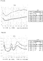
- FIG.6A is a graph showing spectral reflectances(%) of the coatings (920 three-dimensional coating, 920 flat coating) produced under the conditions of Example 1 and Example 21, and FIG.6B is a graph showing the spectral reflectances(%) of the coatings (3702 three-dimensional coating, 3702 flat coating) produced under the conditions of Example 11 and Example 22 in the short wavelength region (250 to 2500nm).
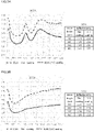
- FIG.7A is a graph showing spectral reflectances(%) of the coatings (3402 three-dimensional coating, 3402 flat coating) produced under each of the conditions of Example 12 and Example 23, and FIG.7B is a graph showing spectral reflectances(%) of the coatings (6331 three-dimensional coating, 6331 flat coating) produced under the conditions of Example 13 and Example 24 in the short wavelength region (250 to 2500nm).
- FIG.8A is a graph showing spectral reflectances(%) of the coatings (965 three-dimensional coating, 965 flat coating) produced under the conditions of Example 14 and Example 25, and FIG.8B is a graph showing spectral reflectances(%) of the coatings (1G three-dimensional coating, 1G flat coating) (250 to 2500 nm) produced under the conditions of Example 15 and Example 26 in the short wavelength region (250 to 2500nm).
- FIG.9A is a graph showing spectral reflectances(%) of the coatings (302A three-dimensional coating, 302A flat coating) produced under each of the conditions of Example 16 and Example 27, and FIG.9B is a graph showing spectral reflectances(%) of the coating (303B three-dimensional coating, 303B flat coating) in the short wavelength region (250 to 2500nm).
- FIG.10A is a graph showing spectral reflectances(%) of the coatings (6301 three-dimensional coating, 6301 flat coating) produced under each of the conditions of Example 18 and Example 29, and FIG.10B is a graph showing spectral reflectances(%) of the coatings (6340 three-dimensional coating, 6340 flat coating) in the short wavelength region (250 to 2500nm).
- FIG.11 is a graph showing the spectral reflectances(%) in the short wavelength region (250 to 2500 nm) of the coatings (444 three-dimensional coating, 444 flat coating) produced under the respective conditions of Example 20 and Example 31.
- the horizontal axis represents the wavelength(nm) and the vertical axis represents the spectral reflectance(%).
- the broken line shows a flat coating and the solid line shows a three-dimensional coating.
- the spectral reflectance of each of the coatings is shown at wavelengths of 400, 500, 600 and 700nm.
- the spectral reflectance of each of the three-dimensional coatings was less than 5% at a wavelength of 400 to 700 nm in the visible light region.
- the three coatings "6331", “303B” and "444" show spectral reflectance of less than 5% at a wavelength of 400 to 700 nm, other flat coatings exhibited a spectral reflectance of 5% or more at any wavelength in the above wavelength range.
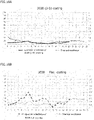
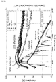
- FIG.12A is a graph showing the spectral reflectance(%) and the thermal emittance in the long wavelength region, of the coating (920 three-dimensional coating) produced under the condition of Example 1
- FIG.12B is a graph showing the spectral reflectance(%) and the thermal emittance in the long wavelength region, of the coating (920 flat coating) produced under the condition of Example 21
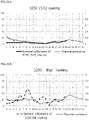
- FIG.13A is a graph showing the spectral reflectance(%) and the thermal emittance in the long wavelength region of the coating (3702 three-dimensional coating) produced under the condition of Example 11
- FIG.13B is a graph showing the spectral reflectance(%) and the thermal emittance in the long wavelength region of the coating (3702 flat coating) produced under the condition of Example 22.
- FIG.14A is a graph showing the spectral reflectance(%) and the thermal emittance in the long wavelength region of the coating (3402 three-dimensional coating) produced under the condition of Example 12
- FIG.14B is a graph showing the spectral reflectance(%) and the thermal emittance in the long wavelength region of the coating (3402 flat coating) produced under the condition of Example 23
- FIG.15A is a graph showing the spectral reflectance(%) and the thermal emittance in the long wavelength region of the coating (6331 stereo coating) produced under the condition of Example 13
- FIG.15B is a graph showing the spectral reflectance(%) and the thermal emittance in the long wavelength region of the coating (6331 flat coating) produced under the condition of Example 24.
- FIG.16A is a graph showing the spectral reflectance(%) and the thermal emittance in the long wavelength region of the coating (965 stereo coating) produced under the condition of Example 14, and FIG.16B is a graph showing the spectral reflectance(%) and the thermal emittance in the long wavelength region of the coating (965 flat coating) produced under the condition of Example 25.
- FIG.17A is a graph showing the spectral reflectance(%) and the thermal emittance in the long wavelength region of the coating (302A three-dimensional coating) produced under the condition of Example 16
- FIG.17B is a graph showing the spectral reflectance(%) and the thermal emittance in the long wavelength region of the coating (302A flat coating) produced under the condition of Example 27.
- FIG.18A is a graph showing the spectral reflectance(%) and the thermal emittance in the long wavelength region of the coating (303B three-dimensional coating) produced under the condition of Example 17, and FIG.18B is a graph showing the spectral reflectance(%) and the thermal emittance in the long wavelength region of the coating (303B flat coating) produced under the condition of Example 28.
- the horizontal axis indicates the wavelength ( ⁇ m)
- the vertical axis on the left side indicates spectral reflectance
- the right side on the vertical axis indicates the thermal emittance (1 at the bottom and 0 at the top).
- the thermal emittance is indicated by the ratio of the thermal emittance of a perfect black body to 1.
- thick lines indicate spectral reflectance and thin lines indicate thermal emittance, respectively.
- the three-dimensional coating is indicated by a solid line on the graph and the flat coating is indicated by a broken line on the graph.
- thermal emittance means that the absorbed solar heat is radiated outward as an electromagnetic wave. For this reason, thermal emittance is preferably close to zero.
- the ideal coating has a light absorptance of 100% as perfect black body and does not radiate heat to the outward direction (the thermal emittance is zero). Such a coating does not actually exist, but the greater the difference between the spectral absorptance and the thermal emittance, the better the coating. In contrast, an undesirable coating has a high the thermal emittance although its spectral absorptance is low and the heat absorbing power is weak, since it is difficult to absorb sunlight but easy to radiate the heat brought by the absorbed light.
- the perfect black body has a spectral absorptance of 100% (spectral reflectance 0%) and a thermal emittance of 1, it is found that the equilibrium can be changed by the structure of the coatings etc.
- the absorber of solar heat power generation has a low spectral reflectance (high spectral absorptance) and low thermal emittance, and it is desirable to have a difference between these numerical values as much as possible.
- the spectral reflectance is slightly lower than the thermal emittance at the wavelength of 2 to 5 ⁇ m, the same or slightly higher.
- the spectral reflectance remarkably tended to exceed the thermal emittance. That is, it is considered that the heat radiation becomes high while the spectral reflectance is high (spectral absorptance is poor), which is unsuitable for solar heat power generation.
- the three-dimensional coatings of "920”, “303B” and “302A” it was confirmed that the spectral absorptance exceeded the thermal emittance. Even the other coatings (for example, "965", "6331” or "3402”) also showed the same tendency by forming the three-dimensional coating.
- An absorber coating having a three-layer structure including a base coating was produced by the following method.
- 3g of an organotitanium polymer (product number: B-10, tetra-n-butoxytitanium polymer) manufactured by Nippon Soda Co., Ltd. 6g of isopropyl diglycol (iPDG) manufactured by Nippon Nyukazai Co., Ltd. and 1.85g of 1-butanol (first grade reagent) manufactured by Wako Pure Chemical Industries were combined and mixed by ultrasonic irradiation for 15 minutes in an ultrasonic washer (trade name: Bransonic) manufactured by Branson.
- 306.963g of 2-propanol was added to the reaction mixture to dilute the reaction solution.
- 12.5g of powdered metal oxide "3250" was mixed and sonicated for 30 minutes.
- the mixture (also referred to as a mixed solution) obtained in the above steps was placed in a spray device (spray gun made by HARDER & STEENBECK, 0.4 mm nozzle, trade name: Colani).
- the coating was formed by spraying on the base coating for 110 seconds while moving the spray from one end side to the other end side of the base coating maintaining the temperature of 350°C.
- the pressure during spraying was 0.2MPa.
- the titanium precursor as the raw material of the absorber coating solidifies the metal oxide particles upon thermal decomposition and crystallization on the heater and pores are produced by evaporation of the organic solvent. This process was repeated several times while maintaining the temperature of the substrate surface.
- a mixed solution of 20.83g of TEOS and 63.36g of ethanol, a mixture of 7.41g of HA, 63.36g of ethanol, and 9.01g of ion exchanged water were mixed and stood at 40°C.
- samples 1 to 8 Eight samples (3 ⁇ 3cm square) (hereinafter referred to as "samples 1 to 8") were prepared for the thermal durability test below.
- Example 32 Absorber coating (3250 (3-D)) Base coating (3250 flat) Network area ( ⁇ m 2) 157770.473 49327.742 Projected area ( ⁇ m 2 ⁇ 15649.473 15491.455 Network area /Projected area 10.0815 3.1842 Ra ( ⁇ m ⁇ 3.019 0.357 Rz ( ⁇ m ⁇ 37.575 10.11
- FIG.20 is a graph showing the spectral reflectance (%) in the short wavelength region (250 to 2500nm) of the absorber coating (3250 (3-D) coating) and the base coating (3250 flat coating) prepared in Example 32. It is similar to the results shown in FIGS.6 to 11 that the three-dimensional coating has a lower spectral reflectance than the flat coating, that is, the spectral absorptance is higher. In addition, the spectral reflectance of the three-dimensional coating was as small as less than 4% at a wavelength of 400 to 700 nm in the visible light region, showing a significant difference as compared with the flat coating.
- FIG.21A is a graph showing the spectral reflectance (%) and the thermal emittance in the long wavelength region (2 to 25 ⁇ m) of the absorber coating (3250 3-D coating) prepared in Example 32.
- FIG.21B is a graph showing the spectral reflectance (%) and the thermal emittance in the long wavelength region (2 to 25 ⁇ m) of the base coating (3250 flat coating) prepared in Example 32.
- the spectral reflectance slightly falls below the thermal emittance in the wavelength region from 2 to 5 ⁇ m, but in the region of 5 ⁇ m or more, the spectral reflectance tends to be significantly higher than the thermal emittance in the specific wavelength region.
- the 3250 three-dimensional coating it was confirmed that the value of the spectral reflectance is small and the spectral absorptance exceeds the thermal emittance.
- Thermal durability test and spectral absorptance measurement were conducted at Australian National University (ANU). The thermal durability tests were carried out for 10 hours, 20 hours or 100 hours at temperatures of 600°C, 750°C or 850°C, respectively, and compared with coatings prepared using Pyromark 2500 which is a highly heat-resistant silicone coating material as a control. Thermal durability test was carried out by placing the sample (coating + substrate) in a programmed muffle furnace. Temperature up and down were set at 3°C/min. In this test, the time to reach the target temperature and return to room temperature is added to the thermal durability test time.
- FIG.22 is the spectral absorptance measurement data of the eight samples (three-layer coating) prepared in Example 32 before the thermal durability test. In the wavelength region of 400 to 2500nm, the solar-weighted absorptance of these eight samples was extremely uniform as 96.91% ⁇ 0.08%.
- FIG.23 shows the results of comparing the spectral absorptance before the thermal durability test of the three-layer coating (Sample 8) (indicated as 3250 in the drawing) prepared in Example 32 with the control coating (indicated as Pyromark in the drawing).
- the horizontal axis represents the measurement wavelength, and the vertical axis represents the spectral absorptance.
- Each coating is coated on the same heat-resistant stainless-steel substrate (SS 253 MA). As shown in FIG.23 , it can be seen that the three-layer coating prepared in Example 32 has a much higher absorptance than that of the control coating.
- FIG.24 shows the spectral absorptances before and after the thermal durability test at 600°C for the three-layer coating (indicated as 3250 in the drawing) prepared in Example 32.
- Samples 7 and 6 were subjected to the thermal durability test at 600°C for 10 hours and 100 hours, respectively.
- Sample 6 was performed at first a thermal durability test for 10 hours at 600°C, measured the spectral absorptance at room temperature, and then heated at 600°C for 90 hours to measure the spectral absorptance again.
- the solar radiation intensity is shown on the second axes.
- Sample 7 and sample 6 also showed a lower spectral absorptance in the lower wavelength range than the control coating (Pyromark).
- FIG.25 shows the measurement results of the spectral absorptance before and after the thermal durability test at 750°C for the three-layer coating (indicated as 3250 in the drawing) prepared in Example 32.
- a thermal durability test (10 hours and 100 hours (10+90 hours) at 750°C was performed for Samples 5 and 4 by the same method as the 600°C thermal durability test.
- Sample 4 was measured for spectral absorptance by adding 90 hours after 10 hours of thermal durability test.
- the solar-weighted absorptance was shown in Table 8. Although the measurement result was similar to 600°C, the spectral absorptance decrease after 100 hours compared with that before the durability test was lower than the test at 600°C.
- FIG.26 shows the measurement results of the spectral absorptance before and after the thermal durability test at 850°C for the three-layer coating (indicated as 3250 in the drawing) prepared in Example 32.
- the thermal durability test was conducted for sample 3 for 10 hours, sample 1 for 20 hours and sample 2 for 100 hours. Sample 1 was initially conducted for 10 hours and an additional 10 hour-thermal durability test was performed. Sample 2 was subjected to a thermal durability test for 10 hours at the beginning and then for an additional 90 hours.
- the solar-weighted absorptance results were shown in Table 9.
- the absorber coating for solar heat power generation according to the present invention can be utilized for concentration solar power generation.
Landscapes
- Engineering & Computer Science (AREA)
- Chemical & Material Sciences (AREA)
- Physics & Mathematics (AREA)
- Organic Chemistry (AREA)
- Combustion & Propulsion (AREA)
- Thermal Sciences (AREA)
- Sustainable Development (AREA)
- Sustainable Energy (AREA)
- Mechanical Engineering (AREA)
- General Engineering & Computer Science (AREA)
- Life Sciences & Earth Sciences (AREA)
- Inorganic Chemistry (AREA)
- Chemical Kinetics & Catalysis (AREA)
- Materials Engineering (AREA)
- Spectroscopy & Molecular Physics (AREA)
- Other Surface Treatments For Metallic Materials (AREA)
- Application Of Or Painting With Fluid Materials (AREA)
- Photometry And Measurement Of Optical Pulse Characteristics (AREA)
- Light Receiving Elements (AREA)
- Inorganic Compounds Of Heavy Metals (AREA)
- Compounds Of Iron (AREA)
- Paints Or Removers (AREA)
Claims (10)
- Absorberbeschichtung für solarthermische Energieerzeugung,wobei die Beschichtung eine Netzwerkstruktur aus Verbundteilchen aufweist, die Teilchen aus einem Metalloxid, das hauptsächlich zwei oder mehr Metalle, ausgewählt aus Mn, Cr, Cu, Zr, Mo, Fe, Co und Bi, aufweist, und Titanoxid umfasst, das teilweise oder vollständig auf die Oberfläche der Teilchen aus Metalloxid aufgebracht ist,wobei die Oberflächenrauigkeit der Beschichtung 1,0 µm oder mehr im arithmetischen Mittel der Rauigkeit (Ra) beträgt,und das Verhältnis einer Netzwerkfläche des Verbundteilchens zu einer ebenen Fläche der Beschichtung 7 oder mehr beträgt.
- Absorberbeschichtung für solarthermische Energieerzeugung nach Anspruch 1, wobei das Metalloxid hauptsächlich zwei oder mehr Metalle aufweist, die aus Cr, Mn und Cu ausgewählt sind.
- Absorberbeschichtung für solarthermische Energieerzeugung nach Anspruch 1 oder 2, die darüber hinaus eine poröse Siliziumdioxidbeschichtung auf deren Oberseite aufweist.
- Absorberbeschichtung für solarthermische Energieerzeugung nach einem der Ansprüche 1 bis 3, deren optischer Reflexionsgrad in einem Bereich des sichtbaren Lichts mit einer Wellenlänge von 400 bis 700 nm weniger als 5,0 % beträgt.
- Verfahren zur Herstellung der Absorberbeschichtung für solarthermische Energieerzeugung nach einem der Ansprüche 1 bis 4, wobei das Verfahren umfasst:einen ersten Mischschritt des Mischens von Titanalkoxid (A) und Acetylaceton und/oder Ethylacetoacetat (B) in einem molaren Verhältnis von A:B = 1:1 oder mehr,einen zweiten Mischschritt des Mischens der Teilchen aus Metalloxid, das hauptsächlich zwei oder mehr Metalle, ausgewählt aus Mn, Cr, Cu, Zr, Mo, Fe, Co und Bi, aufweist, in dem Gemisch nach dem ersten Mischschritt, undeinen Beschichtungsschritt des Aufbringens des Gemischs nach dem zweiten Mischschritt auf einem Substrat zur Bildung einer Beschichtung.
- Verfahren zur Herstellung der Absorberbeschichtung für solarthermische Energieerzeugung nach Anspruch 5, wobei der Beschichtungsschritt ein Schritt des Aufsprühens des Gemischs auf das auf 250 bis 400°C erwärmte Substrat ist.
- Verfahren zur Herstellung der Absorberbeschichtung für solarthermische Energieerzeugung nach Anspruch 5, wobei der Beschichtungsschritt umfasst:einen Sprühschritt des Aufsprühens des Gemischs auf das Substrat bei einer Temperatur von weniger als 250°C, undeinen Erwärmungsschritt des Erwärmens des Gemischs auf 250 bis 400°C nach dem Sprühschritt.
- Verfahren zur Herstellung der Absorberbeschichtung für solarthermische Energieerzeugung nach einem der Ansprüche 5 bis 7, wobei das Metalloxid hauptsächlich zwei oder mehr Metalle aufweist, die aus Cr, Mn und Cu ausgewählt sind.
- Verfahren zur Herstellung der Absorberbeschichtung für solarthermische Energieerzeugung nach einem der Ansprüche 5 bis 8, darüber hinaus mit einem Siliziumdioxid-Beschichtungsschritt zur Bildung einer porösen Siliziumdioxid-Beschichtung auf deren Oberseite.
- Verfahren zur Herstellung der Absorberbeschichtung für solarthermische Energieerzeugung nach einem der Ansprüche 5 bis 9, wobei ein spektraler Reflexionsgrad der Beschichtung in einem Bereich des sichtbaren Lichts einer Wellenlänge von 400 bis 700 nm weniger als 5,0 % beträgt.
Applications Claiming Priority (2)
| Application Number | Priority Date | Filing Date | Title |
|---|---|---|---|
| JP2017010110 | 2017-01-24 | ||
| PCT/JP2017/034545 WO2018138965A1 (ja) | 2017-01-24 | 2017-09-25 | 太陽熱発電用集熱膜およびその製造方法 |
Publications (3)
| Publication Number | Publication Date |
|---|---|
| EP3575706A1 EP3575706A1 (de) | 2019-12-04 |
| EP3575706A4 EP3575706A4 (de) | 2020-07-08 |
| EP3575706B1 true EP3575706B1 (de) | 2022-07-27 |
Family
ID=62978523
Family Applications (1)
| Application Number | Title | Priority Date | Filing Date |
|---|---|---|---|
| EP17893530.0A Active EP3575706B1 (de) | 2017-01-24 | 2017-09-25 | Absorberbeschichtung für solarthermische energieerzeugung und herstellungsverfahren dafür |
Country Status (11)
| Country | Link |
|---|---|
| US (1) | US11002466B2 (de) |
| EP (1) | EP3575706B1 (de) |
| JP (1) | JP6376311B1 (de) |
| AU (1) | AU2017395200B2 (de) |
| CL (1) | CL2019000794A1 (de) |
| DK (1) | DK3575706T3 (de) |
| ES (1) | ES2701573B2 (de) |
| MA (1) | MA45751B1 (de) |
| PT (1) | PT3575706T (de) |
| WO (1) | WO2018138965A1 (de) |
| ZA (1) | ZA201904216B (de) |
Families Citing this family (3)
| Publication number | Priority date | Publication date | Assignee | Title |
|---|---|---|---|---|
| CN116209872A (zh) * | 2020-09-28 | 2023-06-02 | 佳能株式会社 | 储热装置及其制造方法 |
| CN114623605B (zh) * | 2020-12-14 | 2023-08-22 | 清华大学 | 太阳能集热器及太阳能热水器 |
| WO2023282336A1 (en) * | 2021-07-08 | 2023-01-12 | Nano Frontier Technology Co., Ltd. | Improvements to light absorbing surfaces |
Family Cites Families (29)
| Publication number | Priority date | Publication date | Assignee | Title |
|---|---|---|---|---|
| US3496011A (en) * | 1965-09-10 | 1970-02-17 | North American Rockwell | Method of coating thermally emissive surface with a composite radiation control coating and resulting article |
| JPS5296429A (en) * | 1976-02-09 | 1977-08-13 | Agency Of Ind Science & Technol | Solar energy collecting member and production thereof |
| US4268319A (en) * | 1978-03-01 | 1981-05-19 | Exxon Research & Engineering Co. | High temperature solar absorber coating and method of applying same |
| JPS5641383A (en) * | 1979-09-12 | 1981-04-18 | Pentel Kk | Preparation of selective absorbing surface |
| US4356815A (en) * | 1980-08-19 | 1982-11-02 | Owens-Illinois, Inc. | Solar energy collector having an absorber element of coated foil |
| JPS57112640A (en) * | 1980-12-30 | 1982-07-13 | Matsushita Electric Works Ltd | Solar heat absorbent and manufacture thereof |
| JPS57203778A (en) * | 1981-06-09 | 1982-12-14 | Mitsubishi Electric Corp | Manufacture of absorbing surface for solar heat collector |
| JPS5843361A (ja) * | 1981-09-09 | 1983-03-14 | Matsushita Electric Ind Co Ltd | 太陽熱集熱器 |
| US4735861A (en) * | 1987-07-13 | 1988-04-05 | Ford Motor Company | Coated glass substrate |
| DE4344258C1 (de) | 1993-12-23 | 1995-08-31 | Miladin P Lazarov | Material aus chemischen Verbindungen mit einem Metall der Gruppe IV A des Periodensystems, Stickstoff und Sauerstoff, dessen Verwendung und Verfahren zur Herstellung |
| US5670248A (en) | 1994-07-15 | 1997-09-23 | Lazarov; Miladin P. | Material consisting of chemical compounds, comprising a metal from group IV A of the periodic system, nitrogen and oxygen, and process for its preparation |
| US5693134A (en) * | 1994-12-29 | 1997-12-02 | Merck Patent Gesellschaft Mit Beschrankter Haftung | Gray interference pigment and process for producing the same |
| US7507479B2 (en) * | 1998-08-13 | 2009-03-24 | Ppg Industries Ohio, Inc. | Compositions and methods for forming coatings of selected color on a substrate and articles produced thereby |
| JP2001099497A (ja) * | 1999-09-30 | 2001-04-13 | Nisshin Steel Co Ltd | 太陽熱集熱板 |
| DE102004010689B3 (de) * | 2004-02-27 | 2005-06-30 | Schott Ag | Absorber mit einer strahlungsselektiven Absorberbeschichtung und Verfahren zu seiner Herstellung |
| JP2006001820A (ja) * | 2004-06-21 | 2006-01-05 | Dainatsukusu:Kk | カーボン含有チタンオキシナイトライド選択吸収膜 |
| DE102005041763A1 (de) | 2005-09-01 | 2007-03-08 | Basf Ag | Polyisocyanurat Hartschaum und Verfahren zur Herstellung |
| DE102006028429B3 (de) * | 2006-06-21 | 2007-06-28 | Fachhochschule Kiel | Verfahren zur Herstellung einer Absorberbeschichtung auf Sol-Gel-Basis für Solarthermie |
| JP2009023887A (ja) * | 2007-07-20 | 2009-02-05 | Dainatsukusu:Kk | カーボン含有チタンオキシナイトライドと、それを用いた選択吸収膜および太陽光集熱器と、多孔体 |
| ES2316321B2 (es) * | 2008-10-20 | 2010-12-14 | Abengoa Solar New Technologies, S.A. | Recubrimiento absorbente selectivo solar y metodo de fabricacion. |
| EP2243860A3 (de) * | 2009-04-24 | 2011-11-23 | ZYRUS Beteiligungsgesellschaft mbH & Co. Patente I KG | Verfahren zur Herstellung einer Solarabsorberbeschichtung |
| DE102009048672A1 (de) * | 2009-09-30 | 2011-03-31 | Siemens Aktiengesellschaft | Zentralrohr für ein linear konzentrierendes solarthermisches Kraftwerk mit Absorberschicht sowie Verfahren zum Aufbringen dieser Absorberschicht |
| JP5632704B2 (ja) * | 2010-10-25 | 2014-11-26 | イビデン株式会社 | 集熱レシーバー及び太陽熱発電装置 |
| JP5119407B2 (ja) | 2011-03-28 | 2013-01-16 | 国立大学法人信州大学 | 光吸収膜、その製造方法およびそれを用いた太陽光集熱器 |
| WO2012172148A1 (es) * | 2011-06-16 | 2012-12-20 | Consejo Superior De Investigaciones Científicas (Csic) | Recubrimiento absorbente selectivo a la radiación visible e infrarroja y su procedimiento de obtención |
| ITBA20110036A1 (it) * | 2011-06-30 | 2012-12-31 | Solari Srl Costruzioni | Metodo per la realizzazione di un assorbitore solare selettivo mediante tecnica sol-gel |
| US9726402B2 (en) * | 2013-02-08 | 2017-08-08 | Council Of Scientific & Industrial Research | Hybrid multilayer solar selective coating for high temperature solar thermal applications and a process for the preparation thereof |
| JP6302694B2 (ja) | 2014-02-07 | 2018-03-28 | 初一 松本 | 太陽熱発電装置 |
| US10184051B2 (en) | 2014-03-13 | 2019-01-22 | The Regents Of The University Of California | Solar energy absorbing coatings and methods of fabrication |
-
2017
- 2017-09-25 EP EP17893530.0A patent/EP3575706B1/de active Active
- 2017-09-25 WO PCT/JP2017/034545 patent/WO2018138965A1/ja not_active Ceased
- 2017-09-25 US US16/477,954 patent/US11002466B2/en active Active
- 2017-09-25 PT PT178935300T patent/PT3575706T/pt unknown
- 2017-09-25 AU AU2017395200A patent/AU2017395200B2/en active Active
- 2017-09-25 MA MA45751A patent/MA45751B1/fr unknown
- 2017-09-25 JP JP2018516102A patent/JP6376311B1/ja active Active
- 2017-09-25 DK DK17893530.0T patent/DK3575706T3/da active
- 2017-09-25 ES ES201890082A patent/ES2701573B2/es active Active
-
2019
- 2019-03-26 CL CL2019000794A patent/CL2019000794A1/es unknown
- 2019-06-27 ZA ZA2019/04216A patent/ZA201904216B/en unknown
Also Published As
| Publication number | Publication date |
|---|---|
| CL2019000794A1 (es) | 2019-06-28 |
| ES2701573R1 (es) | 2019-03-13 |
| EP3575706A4 (de) | 2020-07-08 |
| ES2701573B2 (es) | 2020-06-01 |
| AU2017395200A1 (en) | 2019-02-21 |
| ZA201904216B (en) | 2022-08-31 |
| ES2701573A2 (es) | 2019-02-22 |
| MA45751A1 (fr) | 2020-03-31 |
| PT3575706T (pt) | 2022-09-23 |
| EP3575706A1 (de) | 2019-12-04 |
| AU2017395200B2 (en) | 2021-10-21 |
| JPWO2018138965A1 (ja) | 2019-01-31 |
| WO2018138965A1 (ja) | 2018-08-02 |
| MA45751B1 (fr) | 2021-02-26 |
| DK3575706T3 (da) | 2022-09-05 |
| US11002466B2 (en) | 2021-05-11 |
| JP6376311B1 (ja) | 2018-08-22 |
| US20190368781A1 (en) | 2019-12-05 |
Similar Documents
| Publication | Publication Date | Title |
|---|---|---|
| Wang et al. | Efficient photothermal deicing employing superhydrophobic plasmonic MXene composites | |
| Atchuta et al. | Nickel doped cobaltite spinel as a solar selective absorber coating for efficient photothermal conversion with a low thermal radiative loss at high operating temperatures | |
| EP2780646B1 (de) | Solarthermisches umwandlungselement, solarthermischer umwandlungsstapel, solarthermische umwandlungsvorrichtung und solarthermisch stromerzeugungsvorrichtung | |
| Dandapat et al. | The fabrication of BiOCl x Br 1− x/alumina composite films with highly exposed {001} facets and their superior photocatalytic activities | |
| Pal et al. | Spectrally selective absorber coating from transition metal complex for efficient photothermal conversion | |
| EP3575706B1 (de) | Absorberbeschichtung für solarthermische energieerzeugung und herstellungsverfahren dafür | |
| Ma et al. | Solution combustion of spinel CuMn2O4 ceramic pigments for thickness sensitive spectrally selective (TSSS) paint coatings | |
| Geng et al. | Low-temperature combustion synthesis of CuCr2O4 spinel powder for spectrally selective paints | |
| Karthick Kumar et al. | Nanostructured CuO thin films prepared through sputtering for solar selective absorbers | |
| KalužA et al. | Structural and IR spectroscopic analysis of sol-gel processed CuFeMnO4 spinel and CuFeMnO4/silica films for solar absorbers | |
| CA2656046A1 (en) | Process for producing a sol-gel-based absorber coating for solar heating | |
| Xu et al. | Spinel Cu–Mn–Cr oxide nanoparticle-pigmented solar selective coatings maintaining> 94% efficiency at 750° C | |
| Ambrosini et al. | Improved high temperature solar absorbers for use in concentrating solar power central receiver applications | |
| Geng et al. | Sol–gel combustion‐derived CoCuMnOx spinels as pigment for spectrally selective paints | |
| Ke et al. | Solar selective coatings with multilayered structure based on thermal spraying WC-Co solar absorption layer | |
| Ma et al. | CuCr2O4 spinel ceramic pigments synthesized by sol-gel self-combustion method for solar absorber coatings | |
| Krins et al. | Thick and crack-free nanocrystalline mesoporous TiO2 films obtained by capillary coating from aqueous solutions | |
| Tong et al. | Synthesis, characterization, and NIR reflectance of highly dispersed NiTiO3 and NiTiO3/TiO2 composite pigments | |
| Ma et al. | Cu1. 5Mn1. 5O4-based ceramic spectrally selective coatings for efficient solar absorber applications | |
| CN103691647B (zh) | 一种具有尖晶石结构的太阳能选择吸收薄膜的制备方法 | |
| Gao et al. | Optical property and thermal performance of hollow glass microsphere/BiOBr1-xIx composites as a novel colored near infrared reflective pigment | |
| AU2013289616B2 (en) | Microwave curing of multi-layer coatings | |
| KR20170023527A (ko) | 습식 공정을 이용한 고효율 태양열 흡수체 박막 및 그 제조방법 | |
| Manjumol et al. | A hybrid sol–gel approach for novel photoactive and hydrophobic titania coatings on aluminium metal surfaces | |
| Warwick et al. | Electric fields in the chemical vapour deposition growth of vanadium dioxide thin films |
Legal Events
| Date | Code | Title | Description |
|---|---|---|---|
| STAA | Information on the status of an ep patent application or granted ep patent |
Free format text: STATUS: THE INTERNATIONAL PUBLICATION HAS BEEN MADE |
|
| PUAI | Public reference made under article 153(3) epc to a published international application that has entered the european phase |
Free format text: ORIGINAL CODE: 0009012 |
|
| STAA | Information on the status of an ep patent application or granted ep patent |
Free format text: STATUS: REQUEST FOR EXAMINATION WAS MADE |
|
| 17P | Request for examination filed |
Effective date: 20190812 |
|
| AK | Designated contracting states |
Kind code of ref document: A1 Designated state(s): AL AT BE BG CH CY CZ DE DK EE ES FI FR GB GR HR HU IE IS IT LI LT LU LV MC MK MT NL NO PL PT RO RS SE SI SK SM TR |
|
| AX | Request for extension of the european patent |
Extension state: BA ME |
|
| DAV | Request for validation of the european patent (deleted) | ||
| DAX | Request for extension of the european patent (deleted) | ||
| A4 | Supplementary search report drawn up and despatched |
Effective date: 20200609 |
|
| RIC1 | Information provided on ipc code assigned before grant |
Ipc: F24S 70/25 20180101ALI20200603BHEP Ipc: F24S 70/225 20180101AFI20200603BHEP |
|
| REG | Reference to a national code |
Ref country code: DE Ref legal event code: R079 Ref document number: 602017060041 Country of ref document: DE Free format text: PREVIOUS MAIN CLASS: F24S0070100000 Ipc: F24S0070225000 |
|
| RIC1 | Information provided on ipc code assigned before grant |
Ipc: C01G 51/00 20060101ALI20220112BHEP Ipc: C01G 49/00 20060101ALI20220112BHEP Ipc: C01G 45/00 20060101ALI20220112BHEP Ipc: C01G 37/00 20060101ALI20220112BHEP Ipc: F24S 70/25 20180101ALI20220112BHEP Ipc: F24S 70/225 20180101AFI20220112BHEP |
|
| GRAP | Despatch of communication of intention to grant a patent |
Free format text: ORIGINAL CODE: EPIDOSNIGR1 |
|
| STAA | Information on the status of an ep patent application or granted ep patent |
Free format text: STATUS: GRANT OF PATENT IS INTENDED |
|
| INTG | Intention to grant announced |
Effective date: 20220222 |
|
| GRAS | Grant fee paid |
Free format text: ORIGINAL CODE: EPIDOSNIGR3 |
|
| GRAA | (expected) grant |
Free format text: ORIGINAL CODE: 0009210 |
|
| STAA | Information on the status of an ep patent application or granted ep patent |
Free format text: STATUS: THE PATENT HAS BEEN GRANTED |
|
| AK | Designated contracting states |
Kind code of ref document: B1 Designated state(s): AL AT BE BG CH CY CZ DE DK EE ES FI FR GB GR HR HU IE IS IT LI LT LU LV MC MK MT NL NO PL PT RO RS SE SI SK SM TR |
|
| REG | Reference to a national code |
Ref country code: CH Ref legal event code: EP |
|
| REG | Reference to a national code |
Ref country code: DE Ref legal event code: R096 Ref document number: 602017060041 Country of ref document: DE |
|
| REG | Reference to a national code |
Ref country code: AT Ref legal event code: REF Ref document number: 1507304 Country of ref document: AT Kind code of ref document: T Effective date: 20220815 |
|
| REG | Reference to a national code |
Ref country code: IE Ref legal event code: FG4D |
|
| REG | Reference to a national code |
Ref country code: DK Ref legal event code: T3 Effective date: 20220829 |
|
| REG | Reference to a national code |
Ref country code: PT Ref legal event code: SC4A Ref document number: 3575706 Country of ref document: PT Date of ref document: 20220923 Kind code of ref document: T Free format text: AVAILABILITY OF NATIONAL TRANSLATION Effective date: 20220919 |
|
| REG | Reference to a national code |
Ref country code: LT Ref legal event code: MG9D |
|
| REG | Reference to a national code |
Ref country code: NL Ref legal event code: MP Effective date: 20220727 |
|
| PG25 | Lapsed in a contracting state [announced via postgrant information from national office to epo] |
Ref country code: SE Free format text: LAPSE BECAUSE OF FAILURE TO SUBMIT A TRANSLATION OF THE DESCRIPTION OR TO PAY THE FEE WITHIN THE PRESCRIBED TIME-LIMIT Effective date: 20220727 Ref country code: RS Free format text: LAPSE BECAUSE OF FAILURE TO SUBMIT A TRANSLATION OF THE DESCRIPTION OR TO PAY THE FEE WITHIN THE PRESCRIBED TIME-LIMIT Effective date: 20220727 Ref country code: NO Free format text: LAPSE BECAUSE OF FAILURE TO SUBMIT A TRANSLATION OF THE DESCRIPTION OR TO PAY THE FEE WITHIN THE PRESCRIBED TIME-LIMIT Effective date: 20221027 Ref country code: NL Free format text: LAPSE BECAUSE OF FAILURE TO SUBMIT A TRANSLATION OF THE DESCRIPTION OR TO PAY THE FEE WITHIN THE PRESCRIBED TIME-LIMIT Effective date: 20220727 Ref country code: LV Free format text: LAPSE BECAUSE OF FAILURE TO SUBMIT A TRANSLATION OF THE DESCRIPTION OR TO PAY THE FEE WITHIN THE PRESCRIBED TIME-LIMIT Effective date: 20220727 Ref country code: LT Free format text: LAPSE BECAUSE OF FAILURE TO SUBMIT A TRANSLATION OF THE DESCRIPTION OR TO PAY THE FEE WITHIN THE PRESCRIBED TIME-LIMIT Effective date: 20220727 Ref country code: FI Free format text: LAPSE BECAUSE OF FAILURE TO SUBMIT A TRANSLATION OF THE DESCRIPTION OR TO PAY THE FEE WITHIN THE PRESCRIBED TIME-LIMIT Effective date: 20220727 Ref country code: ES Free format text: LAPSE BECAUSE OF FAILURE TO SUBMIT A TRANSLATION OF THE DESCRIPTION OR TO PAY THE FEE WITHIN THE PRESCRIBED TIME-LIMIT Effective date: 20220727 |
|
| REG | Reference to a national code |
Ref country code: AT Ref legal event code: MK05 Ref document number: 1507304 Country of ref document: AT Kind code of ref document: T Effective date: 20220727 |
|
| PG25 | Lapsed in a contracting state [announced via postgrant information from national office to epo] |
Ref country code: PL Free format text: LAPSE BECAUSE OF FAILURE TO SUBMIT A TRANSLATION OF THE DESCRIPTION OR TO PAY THE FEE WITHIN THE PRESCRIBED TIME-LIMIT Effective date: 20220727 Ref country code: IS Free format text: LAPSE BECAUSE OF FAILURE TO SUBMIT A TRANSLATION OF THE DESCRIPTION OR TO PAY THE FEE WITHIN THE PRESCRIBED TIME-LIMIT Effective date: 20221127 Ref country code: HR Free format text: LAPSE BECAUSE OF FAILURE TO SUBMIT A TRANSLATION OF THE DESCRIPTION OR TO PAY THE FEE WITHIN THE PRESCRIBED TIME-LIMIT Effective date: 20220727 Ref country code: GR Free format text: LAPSE BECAUSE OF FAILURE TO SUBMIT A TRANSLATION OF THE DESCRIPTION OR TO PAY THE FEE WITHIN THE PRESCRIBED TIME-LIMIT Effective date: 20221028 |
|
| PG25 | Lapsed in a contracting state [announced via postgrant information from national office to epo] |
Ref country code: SM Free format text: LAPSE BECAUSE OF FAILURE TO SUBMIT A TRANSLATION OF THE DESCRIPTION OR TO PAY THE FEE WITHIN THE PRESCRIBED TIME-LIMIT Effective date: 20220727 Ref country code: RO Free format text: LAPSE BECAUSE OF FAILURE TO SUBMIT A TRANSLATION OF THE DESCRIPTION OR TO PAY THE FEE WITHIN THE PRESCRIBED TIME-LIMIT Effective date: 20220727 Ref country code: MC Free format text: LAPSE BECAUSE OF FAILURE TO SUBMIT A TRANSLATION OF THE DESCRIPTION OR TO PAY THE FEE WITHIN THE PRESCRIBED TIME-LIMIT Effective date: 20220727 Ref country code: CZ Free format text: LAPSE BECAUSE OF FAILURE TO SUBMIT A TRANSLATION OF THE DESCRIPTION OR TO PAY THE FEE WITHIN THE PRESCRIBED TIME-LIMIT Effective date: 20220727 Ref country code: AT Free format text: LAPSE BECAUSE OF FAILURE TO SUBMIT A TRANSLATION OF THE DESCRIPTION OR TO PAY THE FEE WITHIN THE PRESCRIBED TIME-LIMIT Effective date: 20220727 |
|
| REG | Reference to a national code |
Ref country code: CH Ref legal event code: PL |
|
| REG | Reference to a national code |
Ref country code: DE Ref legal event code: R097 Ref document number: 602017060041 Country of ref document: DE |
|
| PG25 | Lapsed in a contracting state [announced via postgrant information from national office to epo] |
Ref country code: SK Free format text: LAPSE BECAUSE OF FAILURE TO SUBMIT A TRANSLATION OF THE DESCRIPTION OR TO PAY THE FEE WITHIN THE PRESCRIBED TIME-LIMIT Effective date: 20220727 Ref country code: EE Free format text: LAPSE BECAUSE OF FAILURE TO SUBMIT A TRANSLATION OF THE DESCRIPTION OR TO PAY THE FEE WITHIN THE PRESCRIBED TIME-LIMIT Effective date: 20220727 |
|
| PLBE | No opposition filed within time limit |
Free format text: ORIGINAL CODE: 0009261 |
|
| STAA | Information on the status of an ep patent application or granted ep patent |
Free format text: STATUS: NO OPPOSITION FILED WITHIN TIME LIMIT |
|
| PG25 | Lapsed in a contracting state [announced via postgrant information from national office to epo] |
Ref country code: LU Free format text: LAPSE BECAUSE OF NON-PAYMENT OF DUE FEES Effective date: 20220925 Ref country code: AL Free format text: LAPSE BECAUSE OF FAILURE TO SUBMIT A TRANSLATION OF THE DESCRIPTION OR TO PAY THE FEE WITHIN THE PRESCRIBED TIME-LIMIT Effective date: 20220727 |
|
| 26N | No opposition filed |
Effective date: 20230502 |
|
| PG25 | Lapsed in a contracting state [announced via postgrant information from national office to epo] |
Ref country code: LI Free format text: LAPSE BECAUSE OF NON-PAYMENT OF DUE FEES Effective date: 20220930 Ref country code: IE Free format text: LAPSE BECAUSE OF NON-PAYMENT OF DUE FEES Effective date: 20220925 Ref country code: CH Free format text: LAPSE BECAUSE OF NON-PAYMENT OF DUE FEES Effective date: 20220930 |
|
| PG25 | Lapsed in a contracting state [announced via postgrant information from national office to epo] |
Ref country code: SI Free format text: LAPSE BECAUSE OF FAILURE TO SUBMIT A TRANSLATION OF THE DESCRIPTION OR TO PAY THE FEE WITHIN THE PRESCRIBED TIME-LIMIT Effective date: 20220727 |
|
| PG25 | Lapsed in a contracting state [announced via postgrant information from national office to epo] |
Ref country code: HU Free format text: LAPSE BECAUSE OF FAILURE TO SUBMIT A TRANSLATION OF THE DESCRIPTION OR TO PAY THE FEE WITHIN THE PRESCRIBED TIME-LIMIT; INVALID AB INITIO Effective date: 20170925 |
|
| PG25 | Lapsed in a contracting state [announced via postgrant information from national office to epo] |
Ref country code: CY Free format text: LAPSE BECAUSE OF FAILURE TO SUBMIT A TRANSLATION OF THE DESCRIPTION OR TO PAY THE FEE WITHIN THE PRESCRIBED TIME-LIMIT Effective date: 20220727 |
|
| PG25 | Lapsed in a contracting state [announced via postgrant information from national office to epo] |
Ref country code: MK Free format text: LAPSE BECAUSE OF FAILURE TO SUBMIT A TRANSLATION OF THE DESCRIPTION OR TO PAY THE FEE WITHIN THE PRESCRIBED TIME-LIMIT Effective date: 20220727 |
|
| PG25 | Lapsed in a contracting state [announced via postgrant information from national office to epo] |
Ref country code: BG Free format text: LAPSE BECAUSE OF FAILURE TO SUBMIT A TRANSLATION OF THE DESCRIPTION OR TO PAY THE FEE WITHIN THE PRESCRIBED TIME-LIMIT Effective date: 20220727 |
|
| PG25 | Lapsed in a contracting state [announced via postgrant information from national office to epo] |
Ref country code: MT Free format text: LAPSE BECAUSE OF FAILURE TO SUBMIT A TRANSLATION OF THE DESCRIPTION OR TO PAY THE FEE WITHIN THE PRESCRIBED TIME-LIMIT Effective date: 20220727 |
|
| PGFP | Annual fee paid to national office [announced via postgrant information from national office to epo] |
Ref country code: PT Payment date: 20250911 Year of fee payment: 9 |
|
| PGFP | Annual fee paid to national office [announced via postgrant information from national office to epo] |
Ref country code: DE Payment date: 20250919 Year of fee payment: 9 Ref country code: DK Payment date: 20250923 Year of fee payment: 9 |
|
| PGFP | Annual fee paid to national office [announced via postgrant information from national office to epo] |
Ref country code: IT Payment date: 20250923 Year of fee payment: 9 |
|
| PGFP | Annual fee paid to national office [announced via postgrant information from national office to epo] |
Ref country code: BE Payment date: 20250918 Year of fee payment: 9 Ref country code: GB Payment date: 20250919 Year of fee payment: 9 |
|
| PGFP | Annual fee paid to national office [announced via postgrant information from national office to epo] |
Ref country code: FR Payment date: 20250922 Year of fee payment: 9 |
|
| PG25 | Lapsed in a contracting state [announced via postgrant information from national office to epo] |
Ref country code: TR Free format text: LAPSE BECAUSE OF FAILURE TO SUBMIT A TRANSLATION OF THE DESCRIPTION OR TO PAY THE FEE WITHIN THE PRESCRIBED TIME-LIMIT Effective date: 20220727 |