EP3575656A1 - Method for sealing a sealing layer against edge of through hole and wedge ring used therein - Google Patents
Method for sealing a sealing layer against edge of through hole and wedge ring used therein Download PDFInfo
- Publication number
- EP3575656A1 EP3575656A1 EP19177249.0A EP19177249A EP3575656A1 EP 3575656 A1 EP3575656 A1 EP 3575656A1 EP 19177249 A EP19177249 A EP 19177249A EP 3575656 A1 EP3575656 A1 EP 3575656A1
- Authority
- EP
- European Patent Office
- Prior art keywords
- ring
- clamping ring
- frame
- clamping
- expansion
- Prior art date
- Legal status (The legal status is an assumption and is not a legal conclusion. Google has not performed a legal analysis and makes no representation as to the accuracy of the status listed.)
- Pending
Links
Images


Classifications
-
- F—MECHANICAL ENGINEERING; LIGHTING; HEATING; WEAPONS; BLASTING
- F16—ENGINEERING ELEMENTS AND UNITS; GENERAL MEASURES FOR PRODUCING AND MAINTAINING EFFECTIVE FUNCTIONING OF MACHINES OR INSTALLATIONS; THERMAL INSULATION IN GENERAL
- F16L—PIPES; JOINTS OR FITTINGS FOR PIPES; SUPPORTS FOR PIPES, CABLES OR PROTECTIVE TUBING; MEANS FOR THERMAL INSULATION IN GENERAL
- F16L5/00—Devices for use where pipes, cables or protective tubing pass through walls or partitions
- F16L5/02—Sealing
- F16L5/08—Sealing by means of axial screws compressing a ring or sleeve
-
- E—FIXED CONSTRUCTIONS
- E04—BUILDING
- E04D—ROOF COVERINGS; SKY-LIGHTS; GUTTERS; ROOF-WORKING TOOLS
- E04D13/00—Special arrangements or devices in connection with roof coverings; Protection against birds; Roof drainage; Sky-lights
- E04D13/04—Roof drainage; Drainage fittings in flat roofs, balconies or the like
- E04D13/0404—Drainage on the roof surface
- E04D13/0409—Drainage outlets, e.g. gullies
-
- E—FIXED CONSTRUCTIONS
- E03—WATER SUPPLY; SEWERAGE
- E03C—DOMESTIC PLUMBING INSTALLATIONS FOR FRESH WATER OR WASTE WATER; SINKS
- E03C1/00—Domestic plumbing installations for fresh water or waste water; Sinks
- E03C1/12—Plumbing installations for waste water; Basins or fountains connected thereto; Sinks
- E03C1/20—Connecting baths or bidets to the wastepipe
-
- E—FIXED CONSTRUCTIONS
- E03—WATER SUPPLY; SEWERAGE
- E03F—SEWERS; CESSPOOLS
- E03F5/00—Sewerage structures
- E03F5/04—Gullies inlets, road sinks, floor drains with or without odour seals or sediment traps
- E03F5/0407—Floor drains for indoor use
-
- E—FIXED CONSTRUCTIONS
- E03—WATER SUPPLY; SEWERAGE
- E03F—SEWERS; CESSPOOLS
- E03F5/00—Sewerage structures
- E03F5/04—Gullies inlets, road sinks, floor drains with or without odour seals or sediment traps
- E03F5/0407—Floor drains for indoor use
- E03F5/0409—Devices for preventing seepage around the floor drain
-
- F—MECHANICAL ENGINEERING; LIGHTING; HEATING; WEAPONS; BLASTING
- F16—ENGINEERING ELEMENTS AND UNITS; GENERAL MEASURES FOR PRODUCING AND MAINTAINING EFFECTIVE FUNCTIONING OF MACHINES OR INSTALLATIONS; THERMAL INSULATION IN GENERAL
- F16J—PISTONS; CYLINDERS; SEALINGS
- F16J15/00—Sealings
- F16J15/02—Sealings between relatively-stationary surfaces
- F16J15/021—Sealings between relatively-stationary surfaces with elastic packing
- F16J15/028—Sealings between relatively-stationary surfaces with elastic packing the packing being mechanically expanded against the sealing surface
-
- E—FIXED CONSTRUCTIONS
- E03—WATER SUPPLY; SEWERAGE
- E03F—SEWERS; CESSPOOLS
- E03F5/00—Sewerage structures
- E03F5/04—Gullies inlets, road sinks, floor drains with or without odour seals or sediment traps
- E03F5/0407—Floor drains for indoor use
- E03F5/0408—Floor drains for indoor use specially adapted for showers
Definitions
- the present invention relates to a method according to the preamble of claim 1 for installing a clamping ring to a duct opening in a floor or similar to ensure the tightness of a sealing layer thereon and the opening.
- the invention additionally relates to a clamping ring according to the preamble of claim 8, by means of which the water tightness between the sealing layer of the floor and the duct of the floor is ensured.
- a rigid plastic carpet may also cause the clamping ring to come off, which results in the sealing layer detaching from the floor drain.
- the hardening of the plastic carpet due to aging may cause clamping rings to loosen.
- the tightness, too, with thinner membranes may be insufficient.
- Such a clamping ring becoming detached from the sealing layer may lead to situation where water may find its way under the sealing layer during flooding of a floor drain.
- this installation method of the clamping ring in accordance with the invention is mainly characterised by what is stated in the characterising part of claim 1.
- the inventive clamping ring is, in turn, mainly characterised by what is stated in the characterising part of claim 8.
- Preferred embodiments of the invention are disclosed in the dependent claims.
- the invention is based on the idea that the tightness of a sealing layer and the wall of a floor drain or another duct in the floor is ensured by a member which, when installed in the opening, establishes an adjustable radial pressing force, whereby the pressing force may always be adapted to suit the sealing layer being used.
- the new inventive clamping ring does not, for example, change the dimensioning of the drainage aperture of the floor drain, whereby standard protective floor drain grates may be used to protect the drainage aperture.
- the clamping ring of the invention may also be utilized to squeeze a sealing layer against the wall of any duct, regardless of whether the sealing layer is installed in a floor or wall.
- sealing layer By pressing the sealing layer against an adjacent wall, by utilizing a part protruding from the perimeter of the clamping ring, it is also possible to make sure that sealing layers of different thicknesses may be reliably fastened against the adjacent wall, regardless of their structural thickness.
- the inventive solution provides the additional advantage that the elements affecting the tightness of the joint between the sealing layer and floor drain may be replaced with new parts without replacing the entire floor drain, and thus to be sure of the tightness in the future, too.
- the invention also makes it possible to avoid breaking the frame structures of the floor drain by mechanical fasteners, reducing the leaking risks of the floor drain.
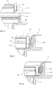
- FIG. 1 The exploded view of Figure 1 shows the first preferred embodiment of the present clamping ring 1.
- the clamping ring assembled in accordance with Figure 2 is shown in Figure 3 , installed in a floor drain 2 known per se.
- the floor drain conventionally comprises a drainage aperture 4 leading to a bowl-like body 3, whereby the body additionally has at least a drain trap 5 and an outlet connection 6 to lead the wastewater led to the floor drain further to a sewage system of the premises.
- the body may comprise one or more side inlets to guide wastewater from a sink and/or washing machine, for instance, to the floor drain. These inlets or the sewage system known per se are not separately shown in the attached drawings.
- the clamping ring 1 according to Figure 1 is thus intended, in particular, to attach a sealing layer 7 to a floor drain 2 or a special extension ring (not shown) adapted to it. Obviously, there is nothing to prevent the use of this clamping ring to seal any floor or wall duct and a sealing layer installed on it against each other.
- Such a sealing layer may be, for example, a sealing flange installed on waterproofing paint, a sealing membrane or a plastic carpet.
- the sealing layer is bent by using work methods known per se in the drainage aperture 4 of the floor drain.
- the waste water led in the floor drain is prevented from getting under the sealing layer surrounding the floor drain by locking the sealing layer 7 by the use of the clamping ring 1 against a collar 8 adjacent to the drainage aperture of the floor drain or the extension ring thereof.
- Such a collar sets on a floor drain arranged in the floor structure so that it is substantially perpendicular to a floor surface 9.
- a mating surface 10 protrudes from the collar, advantageously from the end opposite the floor structure, preventing the clamping ring to be introduced too deep in the body 3.
- the clamping ring has three parts.
- the clamping ring comprises a frame ring 11 and an expansion ring 12 setting against the frame ring.
- a clamping ring seal 13 is arranged between the frame ring and expansion ring coupling thereto.
- the clamping ring seal extends outside an outer mantle of a cylinder formed by the frame ring and expansion ring, whereby its protrusion is adjustable by means of locking means 14, such as screws, mechanically pressing the frame ring and expansion ring against each other.
- locking means 14 such as screws
- clamping ring seal 13 As the clamping ring seal 13 is compressed between the frame ring and expansion ring, it protrudes from the cylindrical outer surface of the clamping ring, enlarging the diameter of the clamping ring seal. At the same time, the clamping ring seal made of elastic material is pressed against the collar of the floor drain, as shown in Figure 6 .
- the frame ring 11 comprises a substantially circular member.
- the member has a face 15 oriented towards the collar 8 of the floor drain 2 or its extension ring, and forming a part of the cylinder outer mantle.
- the frame ring further has a bottom surface 16, which bottom surface, when the frame ring is installed in place in the floor drain, is oriented towards the mating surface 10 protruding from the collar.
- Both the frame ring 11 and expansion ring 12 comprises members 19 and 20 to receive the mechanical locking means. These may include, for example, the perforation that can be seen in Figures 2 and 5 .
- the members receiving the mechanical locking means are placed at intervals along the length of said rings in the corresponding places.
- clamping ring seal 13 When said clamping ring seal 13 is arranged at least partly between the bottom surface 16 and installation surface 17, it may also be provided with members 21 that receive mechanical locking means, to simplify installation.
- the mechanical locking means press both the frame ring 11 and expansion ring 12 against each other, the protrusion of the clamping ring seal outside faces 15 and 18 is achieved.
- the amount of the protrusion may be adjusted, for example, by shaping the faces 15 and 18.
- the frame ring 11 and expansion ring 12 are advantageously made of fibreglass-enforced plastic material, but they may likewise be made of another plastic mixture, metal, or alloy suitable for the purpose.
- the clamping ring seal 13 is advantageously manufactured of a rubber or plastic material having adequate flexibility. As relates to the structure, the frame ring, expansion ring, and clamping ring seal may be solid, but it may also be partly or entirely hollow.
- a pressure ring part 22 present in the clamping ring seal 13 and setting against the faces 15 and 18 may be seen. It is in particular this pressure ring that is adapted to project against the collar 8 of the floor drain as the faces approach each other.
- the faces 15 and 18 sloping against each other that is, by causing a conical recess in the cylindrical part of the outer mantle of the clamping ring 1, the faces that are pressing against each other also achieve a more effective thrust motion, which is exerted on this pressure ring, taking it towards the collar 8.
- the faces orienting against each other are additionally adapted to cause a deformation in the pressure ring, which guides a part of the pressure ring closer to the collar or a sealing ring 23 provided therein, for example.
- the pressure ring 22 surface on the collar side may be provided with a surface profiling that adds to the friction between the pressure ring and collar.
- the pressure ring skirt on the face 18 side may also be formed with a toothing, whereby its deformation, that is, bending towards the collar or, for example, the sealing ring 23 therein is facilitated. Such a toothing is shown in Figure 10 .
- the sealing layer 7 When the sealing layer 7 is installed by the aforementioned embodiment of the present clamping ring 1 to a floor drain 2, for example, the detachment of the sealing layer from the floor drain is prevented by pressing the sealing layer by utilising the clamping ring seal 13 against the collar 8 of the floor drain and/or the sealing ring 23 provided therein, in a manner shown in Figure 4 to 6 , for example.
- the frame ring 11, expansion ring 12, and clamping ring seal 13 with its pressure ring 22 are attached to each other by mechanical locking means 14, as shown in Figure 5 .
- the sealing layer is brought to the duct in a manner known per se, to the drainage aperture of the floor drain, for example, guiding the sealing layer against the collar of the floor drain.
- the clamping ring having a diameter slightly smaller than the diameter of the drainage aperture of the floor drain is pressed into the floor drain.
- the expansion ring pressed into the floor drain advantageously sets against the mating surface 10 in the floor drain while the clamping ring is pressing the sealing layer towards the collar, cf. Figure 6 .
- the frame ring 11 is pressed against the expansion ring 12 by tightening the mechanical locking means 14. Due to the compression, the protrusion of the pressure ring 22 in the clamping ring seal 13 from the cylindrical outer surface of the clamping ring is increased, and the clamping ring seal is pressed against the collar of the floor drain and/or the sealing ring therein.
- a similar working order is utilised when another joint between a duct of a floor or wall and the sealing layer 7 is sealed by pressing the sealing layer against the wall 8 of the duct, such a wall corresponding to the collar of a floor drain as described in the above.
- a second preferred embodiment of the clamping ring 1 comprises two parts partly guided within each other, as shown in Figure 7 .
- Such a clamping ring is hereby formed of the frame ring 11 and expansion ring 12 setting on this frame ring, and the clamping ring seal 13 installed on their outer periphery.
- the frame ring and expansion ring are connected by means of locking means 14, such as screws, mechanically pressing them towards each other.
- both the frame ring and expansion ring have members 19 and 20 to receive the mechanical locking means. These may include, for example, a perforation.
- the members receiving the mechanical locking means are placed at intervals along the length of said rings in the corresponding places.
- These members receiving the locking means are realised so that the members 19 in the frame ring are larger than the locking means, allowing free movement of the locking means in the direction of their longitudinal axis.
- the locking means in the expansion ring are arranged to grab the members 20, whereby the locking means pull the expansion ring against the frame ring.
- the frame ring 11 and expansion ring 12 comprise a base part, from which substantially parallel cylinder means 24 and 25 protrude.
- these cylindrical means set within each other when the frame ring and expansion ring are connected to each other.
- the cylindrical means also define between them a groove 26 in which said clamping ring seal 13 may be arranged.
- the clamping ring seal expands whereby it protrudes and increases the diameter of the clamping ring towards the collar 8 of the floor drain and/or against the sealing ring 23 therein.
- the amount of the protrusion may be adjusted by material selection of the clamping ring seal as well as by selecting different thicknesses for it.
- the third preferred embodiment of the clamping ring 1 comprises two parts partly guidable within each other, as shown in Figures 8 and 9 . Therefore, such a clamping ring is formed exclusively of the frame ring 11 and the expansion ring 12 setting on this frame ring.
- the frame ring and expansion ring are connected by means of locking means 14, such as screws, mechanically pressing them towards each other.
- both the frame ring and expansion ring have members 19 and 20 to receive the mechanical locking means. These may include, for example, the perforation that can be seen in Figures 7 and 8 .
- the members receiving the mechanical locking means are placed at intervals along the length of said rings in the corresponding places.
- These members receiving the locking means are realised so that the members 19 in the frame ring are larger than the locking means, allowing free movement of the locking means in the direction of their longitudinal axis.
- the locking means in the expansion ring are arranged to grab the members 20, whereby the locking means pull the expansion ring against the frame ring.
- the frame ring 11 comprises a substantially circular member.
- the member has a face 15 oriented towards the collar 8 of the floor drain 2 or its extension ring, and forming a part of the cylinder outer mantle.
- the frame ring has a narrowish cylinder part 27 protruding from it in its operational position towards the expansion ring 12, which cylinder part is in its operational position arranged to press by its lower edge against the expansion ring 12 positioned under the frame ring.
- the grip may be further enhanced by arranging a lip 29 at the bottom edge of the cylinder part 27, which presses against the collar 8 or cooperates with the sealing ring 23 in the collar.
- the deformation taking place may in turn be further enhanced by arranging a web 30 in the cylinder part encircling it. Because the material strength of the cylinder part is weaker at such a web, the deformation caused by the compression of the cylindrical surface and directed towards the collar is with a lesser use of force.
- the skirt of the cylinder part 24 on the cylindrical surface 18 side may also be formed toothed or grooved, whereby its deformation, that is, bending towards the collar or the sealing ring 23 therein, is facilitated.
- Such a toothing is shown in Figures 10 and 11.
- the cooperation between the frame ring 11 and expansion ring 12 may be ensured by forming a flange 31 on the expansion ring, which protrudes towards the frame ring and encircles the expansion ring. As shown in Figures 8 and 9 , this flange is arranged to be guided inside the cylinder part 27 of the frame ring as the parts of the clamping ring are connected to each other. When the locking means 14 are being tightened, the cylinder part will thus slide along the flange, hitting the cylindrical surface 28 whereby the outer tip of the cylinder surface is forced in a radial direction towards the collar 8 of the floor drain.
- the sealing layer 7 When the sealing layer 7 is installed by the clamping ring 1 according to the second embodiment present to a floor drain 2, the detachment of the sealing layer from the floor drain is prevented by pressing the sealing layer against the collar 8 of the floor drain and/or the sealing ring 23 present therein, in a manner shown in Figures 7 and 8 .
- the work progresses so that first the frame ring 11 and expansion ring 12 are joined by mechanical locking means 14.
- the clamping ring at this stage has a diameter that is slightly smaller than the diameter of the drainage aperture of the floor drain.
- the clamping ring is pressed into the floor drain and against the sealing layer applied thereto, in a manner known per se.
- a similar working order is utilised when another joint between a duct of a floor or wall and the sealing layer 7 is sealed by pressing the sealing layer against the wall 8 of the duct, such a wall corresponding to the collar of a floor drain as described in the above.
Abstract
Description
- The present invention relates to a method according to the preamble of
claim 1 for installing a clamping ring to a duct opening in a floor or similar to ensure the tightness of a sealing layer thereon and the opening. The invention additionally relates to a clamping ring according to the preamble ofclaim 8, by means of which the water tightness between the sealing layer of the floor and the duct of the floor is ensured. - It is known to connect a sealing membrane or plastic carpet forming the sealing layer of the floor to a floor drain by a so-called clamping ring. In such a case, the sealing membrane or plastic carpet is bent against an inner edge of a drainage aperture on the floor drain. By pressing down a clamping ring in the drain, the sealing membrane or plastic carpet is pressed against a sealing ring on the inner wall of the floor drain. At the same time, the clamping ring is mechanically locked in the claws of the sealing ring or on the inner wall of the floor drain.
- However, there are situations in which a sealing ring cannot achieve a tight enough joint between the sealing membrane or plastic carpet and the inner wall of a floor drain, making it possible for moisture to make it under the sealing layer. The problem arises in the form of the diverse implementations of the sealing layers, whereby their thickness may be notably different from site to site. Therefore, at times thin seal membranes are used, and at times thickish plastic carpets or comparable seals are used. The use of one and same clamping ring to achieve adequate pressing sets major challenges on the dimensioning of the clamping ring. When a sealing layer is made of a plastic carpet, in particular, the thickness of the plastic carpet may make it difficult to press it against the inner wall of a floor drain. A rigid plastic carpet may also cause the clamping ring to come off, which results in the sealing layer detaching from the floor drain. Moreover, it has become apparent that in particular when a plastic carpet is used as a sealing layer, the hardening of the plastic carpet due to aging may cause clamping rings to loosen. The tightness, too, with thinner membranes may be insufficient. Such a clamping ring becoming detached from the sealing layer may lead to situation where water may find its way under the sealing layer during flooding of a floor drain.
- It is thus an object of the invention to establish a new type of clamping ring by means of which water leaks under a sealing layer may be avoided. This object is achieved by the clamping ring and its installation method having the characteristics of the claims in accordance with this invention.
- To be more specific, this installation method of the clamping ring in accordance with the invention is mainly characterised by what is stated in the characterising part of
claim 1. The inventive clamping ring is, in turn, mainly characterised by what is stated in the characterising part ofclaim 8. Preferred embodiments of the invention are disclosed in the dependent claims. - The invention is based on the idea that the tightness of a sealing layer and the wall of a floor drain or another duct in the floor is ensured by a member which, when installed in the opening, establishes an adjustable radial pressing force, whereby the pressing force may always be adapted to suit the sealing layer being used.
- The invention provides considerable advantages. Thus, the new inventive clamping ring does not, for example, change the dimensioning of the drainage aperture of the floor drain, whereby standard protective floor drain grates may be used to protect the drainage aperture.
- The clamping ring of the invention may also be utilized to squeeze a sealing layer against the wall of any duct, regardless of whether the sealing layer is installed in a floor or wall.
- By pressing the sealing layer against an adjacent wall, by utilizing a part protruding from the perimeter of the clamping ring, it is also possible to make sure that sealing layers of different thicknesses may be reliably fastened against the adjacent wall, regardless of their structural thickness.
- When renovating floor drains of bathrooms, for example, the inventive solution provides the additional advantage that the elements affecting the tightness of the joint between the sealing layer and floor drain may be replaced with new parts without replacing the entire floor drain, and thus to be sure of the tightness in the future, too.
- The invention also makes it possible to avoid breaking the frame structures of the floor drain by mechanical fasteners, reducing the leaking risks of the floor drain.
- Other advantages provided by the invention are disclosed in the following more detailed description of specific embodiments of the invention.
- In the following, some preferred embodiments of the invention will be explained in more detail and with reference to the accompanying drawing, in which
-
Figure 1 shows an exploded view of a first embodiment of the present clamping ring; -
Figure 2 shows the clamping ring ofFigure 1 in its assembled form; -
Figure 3 shows a schematic cross-section of the clamping ring according toFigure 1 , installed in a floor drain; -
Figure 4 shows an embodiment of a preassembled clamping ring ofFigure 1 , ready for installation in a floor drain, the clamping ring laying against a sealing layer; -
Figure 5 shows the clamping ring ofFigure 4 pressed with the sealing layer into a floor drain; -
Figure 6 shows the clamping ring ofFigure 4 tightened in place; -
Figure 7 shows a schematic cross-section of a clamping ring according to a second embodiment, installed in a floor drain and with its expanding seals; -
Figure 8 show a schematic cross-section of an expanding clamping ring according to a third embodiment, installed in a floor drain; -
Figure 9 shows the clamping ring ofFigure 8 tightened in place; and -
Figure 10 shows a toothing on a skirt of a cylinder part of the clamping ring according toFigure 8 . - The present figures do not show the clamping in scale but the figures are schematic, illustrating the structure and operation of the preferred embodiments in principle. The structural parts shown by reference numbers in the attached figures then correspond to the structural parts marked by reference numbers in this specification.
- The exploded view of
Figure 1 shows the first preferred embodiment of thepresent clamping ring 1. The clamping ring assembled in accordance withFigure 2 is shown inFigure 3 , installed in afloor drain 2 known per se. The floor drain conventionally comprises adrainage aperture 4 leading to a bowl-like body 3, whereby the body additionally has at least adrain trap 5 and anoutlet connection 6 to lead the wastewater led to the floor drain further to a sewage system of the premises. In addition to the outlet connection, the body may comprise one or more side inlets to guide wastewater from a sink and/or washing machine, for instance, to the floor drain. These inlets or the sewage system known per se are not separately shown in the attached drawings. - The
clamping ring 1 according toFigure 1 is thus intended, in particular, to attach a sealinglayer 7 to afloor drain 2 or a special extension ring (not shown) adapted to it. Obviously, there is nothing to prevent the use of this clamping ring to seal any floor or wall duct and a sealing layer installed on it against each other. - Such a sealing layer may be, for example, a sealing flange installed on waterproofing paint, a sealing membrane or a plastic carpet. Hereby the sealing layer is bent by using work methods known per se in the
drainage aperture 4 of the floor drain. The waste water led in the floor drain is prevented from getting under the sealing layer surrounding the floor drain by locking the sealinglayer 7 by the use of theclamping ring 1 against acollar 8 adjacent to the drainage aperture of the floor drain or the extension ring thereof. Such a collar sets on a floor drain arranged in the floor structure so that it is substantially perpendicular to afloor surface 9. Amating surface 10 protrudes from the collar, advantageously from the end opposite the floor structure, preventing the clamping ring to be introduced too deep in thebody 3. - It is characteristic to the first preferred embodiment of the
clamping ring 1 presented here that the clamping ring has three parts. Thus, the clamping ring comprises aframe ring 11 and anexpansion ring 12 setting against the frame ring. Between the frame ring and expansion ring coupling thereto, aclamping ring seal 13 is arranged. The clamping ring seal extends outside an outer mantle of a cylinder formed by the frame ring and expansion ring, whereby its protrusion is adjustable by means of locking means 14, such as screws, mechanically pressing the frame ring and expansion ring against each other. The diameter of the clamping ring may thus be extended by tightening the frame ring and expansion ring against each other by the locking means. As theclamping ring seal 13 is compressed between the frame ring and expansion ring, it protrudes from the cylindrical outer surface of the clamping ring, enlarging the diameter of the clamping ring seal. At the same time, the clamping ring seal made of elastic material is pressed against the collar of the floor drain, as shown inFigure 6 . - In the present preferred embodiment, the
frame ring 11 comprises a substantially circular member. The member has aface 15 oriented towards thecollar 8 of thefloor drain 2 or its extension ring, and forming a part of the cylinder outer mantle. The frame ring further has abottom surface 16, which bottom surface, when the frame ring is installed in place in the floor drain, is oriented towards themating surface 10 protruding from the collar. Theexpansion ring 12, positioned under the frame ring in its operational position, in turn comprises an mountingsurface 17 oriented towards the bottom surface of the frame ring, and asecond face 18 oriented towards thecollar 8 and forming a part of the cylinder outer mantle. - Both the
frame ring 11 andexpansion ring 12 comprisesmembers Figures 2 and5 . The members receiving the mechanical locking means are placed at intervals along the length of said rings in the corresponding places. - When said clamping
ring seal 13 is arranged at least partly between thebottom surface 16 andinstallation surface 17, it may also be provided withmembers 21 that receive mechanical locking means, to simplify installation. When the mechanical locking means press both theframe ring 11 andexpansion ring 12 against each other, the protrusion of the clamping ring seal outside faces 15 and 18 is achieved. The amount of the protrusion may be adjusted, for example, by shaping thefaces - The
frame ring 11 andexpansion ring 12 are advantageously made of fibreglass-enforced plastic material, but they may likewise be made of another plastic mixture, metal, or alloy suitable for the purpose. The clampingring seal 13 is advantageously manufactured of a rubber or plastic material having adequate flexibility. As relates to the structure, the frame ring, expansion ring, and clamping ring seal may be solid, but it may also be partly or entirely hollow. - The operation of the
clamping ring 1 is described in closer detail inFigures 5 to 7 . In them, apressure ring part 22 present in theclamping ring seal 13 and setting against thefaces collar 8 of the floor drain as the faces approach each other. By making thefaces clamping ring 1, the faces that are pressing against each other also achieve a more effective thrust motion, which is exerted on this pressure ring, taking it towards thecollar 8. In addition, the faces orienting against each other are additionally adapted to cause a deformation in the pressure ring, which guides a part of the pressure ring closer to the collar or a sealingring 23 provided therein, for example. - The
pressure ring 22 surface on the collar side may be provided with a surface profiling that adds to the friction between the pressure ring and collar. The pressure ring skirt on theface 18 side may also be formed with a toothing, whereby its deformation, that is, bending towards the collar or, for example, the sealingring 23 therein is facilitated. Such a toothing is shown inFigure 10 . - When the
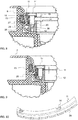
sealing layer 7 is installed by the aforementioned embodiment of thepresent clamping ring 1 to afloor drain 2, for example, the detachment of the sealing layer from the floor drain is prevented by pressing the sealing layer by utilising the clampingring seal 13 against thecollar 8 of the floor drain and/or the sealingring 23 provided therein, in a manner shown inFigure 4 to 6 , for example. At first, theframe ring 11,expansion ring 12, and clampingring seal 13 with itspressure ring 22 are attached to each other by mechanical locking means 14, as shown inFigure 5 . Then, the sealing layer is brought to the duct in a manner known per se, to the drainage aperture of the floor drain, for example, guiding the sealing layer against the collar of the floor drain. Now, the clamping ring having a diameter slightly smaller than the diameter of the drainage aperture of the floor drain is pressed into the floor drain. The expansion ring pressed into the floor drain advantageously sets against themating surface 10 in the floor drain while the clamping ring is pressing the sealing layer towards the collar, cf.Figure 6 . In the final step according toFigure 7 , theframe ring 11 is pressed against theexpansion ring 12 by tightening the mechanical locking means 14. Due to the compression, the protrusion of thepressure ring 22 in theclamping ring seal 13 from the cylindrical outer surface of the clamping ring is increased, and the clamping ring seal is pressed against the collar of the floor drain and/or the sealing ring therein. - A similar working order is utilised when another joint between a duct of a floor or wall and the
sealing layer 7 is sealed by pressing the sealing layer against thewall 8 of the duct, such a wall corresponding to the collar of a floor drain as described in the above. - A second preferred embodiment of the
clamping ring 1 comprises two parts partly guided within each other, as shown inFigure 7 . Such a clamping ring is hereby formed of theframe ring 11 andexpansion ring 12 setting on this frame ring, and theclamping ring seal 13 installed on their outer periphery. The frame ring and expansion ring are connected by means of locking means 14, such as screws, mechanically pressing them towards each other. For this purpose, both the frame ring and expansion ring havemembers members 19 in the frame ring are larger than the locking means, allowing free movement of the locking means in the direction of their longitudinal axis. The locking means in the expansion ring, in turn, are arranged to grab themembers 20, whereby the locking means pull the expansion ring against the frame ring. - In this second preferred embodiment present, the
frame ring 11 andexpansion ring 12 comprise a base part, from which substantially parallel cylinder means 24 and 25 protrude. When the inner diameter of the one of the cylinder means is larger is larger than the outer diameter of the other cylinder means, these cylindrical means set within each other when the frame ring and expansion ring are connected to each other. The cylindrical means also define between them agroove 26 in which said clampingring seal 13 may be arranged. As a result of the frame ring and expansion ring approaching, the clamping ring seal expands whereby it protrudes and increases the diameter of the clamping ring towards thecollar 8 of the floor drain and/or against the sealingring 23 therein. The amount of the protrusion may be adjusted by material selection of the clamping ring seal as well as by selecting different thicknesses for it. - The third preferred embodiment of the
clamping ring 1 comprises two parts partly guidable within each other, as shown inFigures 8 and 9 . Therefore, such a clamping ring is formed exclusively of theframe ring 11 and theexpansion ring 12 setting on this frame ring. The frame ring and expansion ring are connected by means of locking means 14, such as screws, mechanically pressing them towards each other. For this purpose, both the frame ring and expansion ring havemembers Figures 7 and8 . The members receiving the mechanical locking means are placed at intervals along the length of said rings in the corresponding places. These members receiving the locking means are realised so that themembers 19 in the frame ring are larger than the locking means, allowing free movement of the locking means in the direction of their longitudinal axis. The locking means in the expansion ring, in turn, are arranged to grab themembers 20, whereby the locking means pull the expansion ring against the frame ring. - In this second preferred embodiment present, the
frame ring 11 comprises a substantially circular member. The member has aface 15 oriented towards thecollar 8 of thefloor drain 2 or its extension ring, and forming a part of the cylinder outer mantle. The frame ring has anarrowish cylinder part 27 protruding from it in its operational position towards theexpansion ring 12, which cylinder part is in its operational position arranged to press by its lower edge against theexpansion ring 12 positioned under the frame ring. By arranging in the expansion ring acylindrical surface 28 oriented and narrowing towards the frame ring, the tightening of the locking means cause a deformation on the cylinder part. The cylinder part consequently bends, as a result of the frame ring and expansion ring approaching, towards thecollar 8 or the floor drain and/or the sealingring 23 therein. - The grip may be further enhanced by arranging a
lip 29 at the bottom edge of thecylinder part 27, which presses against thecollar 8 or cooperates with the sealingring 23 in the collar. The deformation taking place may in turn be further enhanced by arranging aweb 30 in the cylinder part encircling it. Because the material strength of the cylinder part is weaker at such a web, the deformation caused by the compression of the cylindrical surface and directed towards the collar is with a lesser use of force. - The skirt of the
cylinder part 24 on thecylindrical surface 18 side may also be formed toothed or grooved, whereby its deformation, that is, bending towards the collar or the sealingring 23 therein, is facilitated. Such a toothing is shown inFigures 10 and 11. - The cooperation between the
frame ring 11 andexpansion ring 12 may be ensured by forming aflange 31 on the expansion ring, which protrudes towards the frame ring and encircles the expansion ring. As shown inFigures 8 and 9 , this flange is arranged to be guided inside thecylinder part 27 of the frame ring as the parts of the clamping ring are connected to each other. When the locking means 14 are being tightened, the cylinder part will thus slide along the flange, hitting thecylindrical surface 28 whereby the outer tip of the cylinder surface is forced in a radial direction towards thecollar 8 of the floor drain. - When the
sealing layer 7 is installed by theclamping ring 1 according to the second embodiment present to afloor drain 2, the detachment of the sealing layer from the floor drain is prevented by pressing the sealing layer against thecollar 8 of the floor drain and/or the sealingring 23 present therein, in a manner shown inFigures 7 and8 . The work progresses so that first theframe ring 11 andexpansion ring 12 are joined by mechanical locking means 14. The clamping ring at this stage has a diameter that is slightly smaller than the diameter of the drainage aperture of the floor drain. Next, the clamping ring is pressed into the floor drain and against the sealing layer applied thereto, in a manner known per se. When the clamping ring has settled at the desired depth in the drainage aperture, the pressing offrame ring 11 andexpansion ring 12 against each other is commenced by tightening the mechanical locking means 14. Resulting from the compression, thecylindrical surface 25 of the expansion ring causes an expanding deformation of the clamping ring on thecylinder part 27 of the frame ring. The cylinder part thus bends towards thecollar 8 of the floor drain and/or the sealingring 23 therein. - A similar working order is utilised when another joint between a duct of a floor or wall and the
sealing layer 7 is sealed by pressing the sealing layer against thewall 8 of the duct, such a wall corresponding to the collar of a floor drain as described in the above. - A person skilled in the art will find it obvious that, as technology advances, the basic idea of the invention may be implemented in many different ways. The invention and its embodiments are thus not restricted to the above-described examples but may vary within the scope of the claims.
Claims (15)
- A method for sealing a sealing layer (7) against an edge of a drainage aperture of a duct by using a clamping ring (1), whereby
the sealing layer (7) is pressed against a wall (8) in the duct by means of the clamping ring (1) guided in the duct,
characterised by
forming the clamping ring (1) out of a circular frame ring (11) and expansion ring (12) connected to each other my mechanical locking means (14) so that
as sealing begins, the clamping ring has a diameter that is smaller than the diameter of the drainage aperture of the duct,
guiding the clamping ring to the drainage aperture where it is placed against the sealing layer,
pressing the frame ring (11) and expansion ring (12) of the clamping ring against each other by tightening the mechanical locking means (14),
the frame ring (11) and expansion ring (12) pressed against each other cause a radial expanding deformation of the clamping ring, and the clamping ring presses the sealing layer against the wall (8) and/or a sealing ring (23) therein. - A claim as claimed in claim 1, characterised by
forming on the frame ring (11) in its operational position a cylinder member (24) protruding towards the expansion ring (12) arranged thereto,
forming on the extension frame (12) a cylinder member (25) protruding towards the frame ring,
the cylinder members (24, 25) being guidable in a nested position where they form a groove (26) between them, to which
groove a clamping ring seal (13) is installed, whereby
by tightening the mechanical locking means (14), a deformation takes place in the clamping ring seal (13), as a result of which
the clamping seal ring expands against the wall (8) of the sealing layer and/or the sealing ring (23) therein. - A claim as claimed in claim 1, characterised by
forming on the frame ring (11) in an operational position thereof a cylinder part (27) protruding towards the expansion ring (12) arranged thereto,
forming on the extension frame (12) a cylindrical surface (28) oriented and narrowing towards the frame ring, whereby
by tightening the mechanical locking means (14), a deformation is caused in the cylinder part of the cylinder part and cylindrical part, as a result of which
the cylinder part bends against the wall (8) of the sealing layer and/or the sealing ring (23) therein. - A method as claimed in claim 3, characterised by
arranging, at the bottom edge of the cylinder part (27), a lip (29) which as a result of a force effect caused by the mechanical locking means (14) presses against the wall (8) or is in cooperation with the sealing ring (23) on the wall. - A method as claimed in claim 1, characterised by
arranging a clamping ring seal (13) between the frame ring (11) and expansion ring (12), whereby
the mechanical locking means (14) pressing the frame ring and expansion ring against each other achieve a protrusion in the clamping ring seal (13), developing from the cylindrical outer surface of the clamping ring, and
the clamping ring seal presses against the wall (8) of the duct and/or the sealing ring (23) therein. - A method as claimed in claim 5, characterised by
providing the clamping ring seal (13) with a pressure ring (22) that sets against a face (15) on the frame ring (11) and a face (18) on the expansion ring (12), the
compressing clamping ring seal pushing such a pressure ring towards the wall (8). - A method as claimed in claim 6, characterised by
forming a conical recess in the cylindrical outer mantle part of the clamping ring (1) by making the faces (15) and (18) sloping towards each other, whereby
these faces pressing against each other also exert a pushing movement on the pressure ring, taking it towards the wall (8). - A clamping ring (1) for installation in a floor drain (2) or similar duct,
characterised in that the clamping ring (1) is formed out of
a frame ring (11)
an expansion ring (12) setting against the frame ring,
locking means (14) mechanically pressing the frame ring and expansion ring against each other, and
a part (13, 24) increasing the diameter of the clamping ring by the combined effect of the frame ring and expansion ring. - A clamping ring (1) as claimed in claim 8, characterised in that between the frame ring (11) and expansion ring (13) there is arranged a clamping ring seal (13) extended outside a cylindrical outer mantle formed by the frame ring and expansion ring.
- A clamping ring (1) as claimed in claim 9, characterised in that the clamping ring seal (13) comprises a pressure ring (22) setting against the cylindrical outer mantle of the clamping ring (1).
- A clamping ring (1) as claimed in any one of claims 9 to 10, characterised in that the cylindrical outer mantle of the clamping ring (1) is formed of the face (15) on the frame ring (11) and the face (18) on the expansion ring (12), the faces sloping towards each other, establishing a conical recess in the cylindrical outer mantle of the clamping ring.
- A clamping ring as claimed in any one of claims 8 to 11, characterised in that the clamping ring seal (13) is made of an elastic material.
- A clamping ring (1) as claimed in claim 8, characterised in that
the clamping ring (1) comprises two parts guided partly inside each other so that
the frame ring (11) comprises a substantially circular member, which has a cylinder part (27) protruding towards the expansion ring (12),
the cylinder part is arranged to press in an operational position thereof by its lower edge against the expansion ring and the cylindrical surface (28) oriented and narrowing towards the frame ring contained thereon. - A clamping ring (1) as claimed in claim 13, characterised in that the expansion ring (12) comprises a flange (31) protruding towards the frame ring (11) and encircling the expansion ring, such a
flange being arranged to be guided inside the cylinder part (26) of the frame ring when the parts of the clamping ring (1) are interconnected. - A clamping ring (1) as claimed in claim 14, characterised in that the cylinder part (24) comprises at the lower edge thereof, on the expansion ring (12) side, a lip (29) separated by a web (30) and encircling the expansion ring.
Applications Claiming Priority (1)
| Application Number | Priority Date | Filing Date | Title |
|---|---|---|---|
| FI20185499A FI129847B (en) | 2018-05-31 | 2018-05-31 | Method for sealing a water insulation against the edge of a lead-through hole, and clamping ring for use in the same |
Publications (1)
| Publication Number | Publication Date |
|---|---|
| EP3575656A1 true EP3575656A1 (en) | 2019-12-04 |
Family
ID=67402786
Family Applications (1)
| Application Number | Title | Priority Date | Filing Date |
|---|---|---|---|
| EP19177249.0A Pending EP3575656A1 (en) | 2018-05-31 | 2019-05-29 | Method for sealing a sealing layer against edge of through hole and wedge ring used therein |
Country Status (2)
| Country | Link |
|---|---|
| EP (1) | EP3575656A1 (en) |
| FI (1) | FI129847B (en) |
Citations (4)
| Publication number | Priority date | Publication date | Assignee | Title |
|---|---|---|---|---|
| DE2147489A1 (en) * | 1971-09-23 | 1973-03-29 | Dornier Ag | FLANGE-FREE, SELF-HOLDING THRU SEAL |
| WO1980001701A1 (en) * | 1979-02-09 | 1980-08-21 | G Soederstroem | Floor connection for sewer |
| EP0838623A1 (en) * | 1996-10-24 | 1998-04-29 | Hermann-Heinz Burger Gas- und Wasserarmaturen GmbH | Pressring closure |
| DE202005008176U1 (en) * | 2005-05-20 | 2006-09-28 | Doyma Gmbh & Co | Pipeline duct sealing device for use in building, has sealing body with surface sloped related to edge of body, where material of body is pressed partially and radially for sealing towards wall opening, during axial deforming of body |
-
2018
- 2018-05-31 FI FI20185499A patent/FI129847B/en active IP Right Grant
-
2019
- 2019-05-29 EP EP19177249.0A patent/EP3575656A1/en active Pending
Patent Citations (4)
| Publication number | Priority date | Publication date | Assignee | Title |
|---|---|---|---|---|
| DE2147489A1 (en) * | 1971-09-23 | 1973-03-29 | Dornier Ag | FLANGE-FREE, SELF-HOLDING THRU SEAL |
| WO1980001701A1 (en) * | 1979-02-09 | 1980-08-21 | G Soederstroem | Floor connection for sewer |
| EP0838623A1 (en) * | 1996-10-24 | 1998-04-29 | Hermann-Heinz Burger Gas- und Wasserarmaturen GmbH | Pressring closure |
| DE202005008176U1 (en) * | 2005-05-20 | 2006-09-28 | Doyma Gmbh & Co | Pipeline duct sealing device for use in building, has sealing body with surface sloped related to edge of body, where material of body is pressed partially and radially for sealing towards wall opening, during axial deforming of body |
Also Published As
| Publication number | Publication date |
|---|---|
| FI20185499A1 (en) | 2019-12-01 |
| FI129847B (en) | 2022-09-30 |
Similar Documents
| Publication | Publication Date | Title |
|---|---|---|
| CA2255331C (en) | Undetachable pressed connection between a fitting and a metal pipe end | |
| CA2574678A1 (en) | Hydro penetration prevention sleeve | |
| EP3575656A1 (en) | Method for sealing a sealing layer against edge of through hole and wedge ring used therein | |
| MX2013004506A (en) | Element, preferably a closing element. | |
| US6739597B2 (en) | Drain Gasket | |
| KR101424965B1 (en) | Water pipes for preventing push reward movement of ring-shaped seal | |
| JP4851901B2 (en) | Drain pipe piping structure of building and construction method of the piping structure | |
| US20190010703A1 (en) | Sealing ring and assembly of ducts including said ring | |
| EP2100070B2 (en) | Connection assembly for the connecting of a cylindrical branch of a plastic pipe, and method for the attaching of a cylindrical branch to a plastic pipe | |
| JPH08277538A (en) | Connecting joint for lateral sewer | |
| JP4082550B2 (en) | Manhole flexible joint mounting structure and manhole flexible joint | |
| KR100953158B1 (en) | Branch pipe connector | |
| KR20190139578A (en) | The Construction sleeve with adjustable ring With micro-height control and anti-rotation function | |
| KR101972929B1 (en) | Pipe sealing devices and construction method using the same | |
| JP6086209B2 (en) | Drain pipe connection member | |
| JP3663521B2 (en) | Ground seal anchor head seal structure | |
| JP2737049B2 (en) | Connection method and connection structure between underground structure frame and pipe | |
| KR200482505Y1 (en) | A anchor bolts for Water-proof | |
| KR102299817B1 (en) | Fixed ring for branch pipe in drainage system and coupler of branch pipe in drainage system comprising the same | |
| KR102181963B1 (en) | Waterproof anchor and tunnel waterproofing techniques using that | |
| JP4279278B2 (en) | Wall through structure of wall through pipe and wall through tool of wall through pipe | |
| JPH1089562A (en) | Pipe joint | |
| EP3953633B1 (en) | Sealing assembly | |
| KR20200097468A (en) | Pipe coupling apparatus using quellung reaction | |
| US20060225194A1 (en) | Shower drain assembly |
Legal Events
| Date | Code | Title | Description |
|---|---|---|---|
| PUAI | Public reference made under article 153(3) epc to a published international application that has entered the european phase |
Free format text: ORIGINAL CODE: 0009012 |
|
| STAA | Information on the status of an ep patent application or granted ep patent |
Free format text: STATUS: THE APPLICATION HAS BEEN PUBLISHED |
|
| AK | Designated contracting states |
Kind code of ref document: A1 Designated state(s): AL AT BE BG CH CY CZ DE DK EE ES FI FR GB GR HR HU IE IS IT LI LT LU LV MC MK MT NL NO PL PT RO RS SE SI SK SM TR |
|
| AX | Request for extension of the european patent |
Extension state: BA ME |
|
| STAA | Information on the status of an ep patent application or granted ep patent |
Free format text: STATUS: REQUEST FOR EXAMINATION WAS MADE |
|
| 17P | Request for examination filed |
Effective date: 20200602 |
|
| RBV | Designated contracting states (corrected) |
Designated state(s): AL AT BE BG CH CY CZ DE DK EE ES FI FR GB GR HR HU IE IS IT LI LT LU LV MC MK MT NL NO PL PT RO RS SE SI SK SM TR |
|
| STAA | Information on the status of an ep patent application or granted ep patent |
Free format text: STATUS: EXAMINATION IS IN PROGRESS |
|
| 17Q | First examination report despatched |
Effective date: 20220105 |