EP3575583B1 - Verfahren zur bestimmung einer öffnungszeit eines elektromagnetischen kraftstoffeinspritzers - Google Patents
Verfahren zur bestimmung einer öffnungszeit eines elektromagnetischen kraftstoffeinspritzers Download PDFInfo
- Publication number
- EP3575583B1 EP3575583B1 EP19177134.4A EP19177134A EP3575583B1 EP 3575583 B1 EP3575583 B1 EP 3575583B1 EP 19177134 A EP19177134 A EP 19177134A EP 3575583 B1 EP3575583 B1 EP 3575583B1
- Authority
- EP
- European Patent Office
- Prior art keywords
- time
- voltage
- electromagnetic
- closing
- coil
- Prior art date
- Legal status (The legal status is an assumption and is not a legal conclusion. Google has not performed a legal analysis and makes no representation as to the accuracy of the status listed.)
- Active
Links
Images



Classifications
-
- F—MECHANICAL ENGINEERING; LIGHTING; HEATING; WEAPONS; BLASTING
- F02—COMBUSTION ENGINES; HOT-GAS OR COMBUSTION-PRODUCT ENGINE PLANTS
- F02D—CONTROLLING COMBUSTION ENGINES
- F02D41/00—Electrical control of supply of combustible mixture or its constituents
- F02D41/30—Controlling fuel injection
- F02D41/3082—Control of electrical fuel pumps
-
- F—MECHANICAL ENGINEERING; LIGHTING; HEATING; WEAPONS; BLASTING
- F02—COMBUSTION ENGINES; HOT-GAS OR COMBUSTION-PRODUCT ENGINE PLANTS
- F02D—CONTROLLING COMBUSTION ENGINES
- F02D41/00—Electrical control of supply of combustible mixture or its constituents
- F02D41/20—Output circuits, e.g. for controlling currents in command coils
-
- F—MECHANICAL ENGINEERING; LIGHTING; HEATING; WEAPONS; BLASTING
- F02—COMBUSTION ENGINES; HOT-GAS OR COMBUSTION-PRODUCT ENGINE PLANTS
- F02D—CONTROLLING COMBUSTION ENGINES
- F02D41/00—Electrical control of supply of combustible mixture or its constituents
- F02D41/24—Electrical control of supply of combustible mixture or its constituents characterised by the use of digital means
- F02D41/2406—Electrical control of supply of combustible mixture or its constituents characterised by the use of digital means using essentially read only memories
- F02D41/2425—Particular ways of programming the data
- F02D41/2429—Methods of calibrating or learning
- F02D41/2438—Active learning methods
-
- F—MECHANICAL ENGINEERING; LIGHTING; HEATING; WEAPONS; BLASTING
- F02—COMBUSTION ENGINES; HOT-GAS OR COMBUSTION-PRODUCT ENGINE PLANTS
- F02D—CONTROLLING COMBUSTION ENGINES
- F02D41/00—Electrical control of supply of combustible mixture or its constituents
- F02D41/24—Electrical control of supply of combustible mixture or its constituents characterised by the use of digital means
- F02D41/2406—Electrical control of supply of combustible mixture or its constituents characterised by the use of digital means using essentially read only memories
- F02D41/2425—Particular ways of programming the data
- F02D41/2429—Methods of calibrating or learning
- F02D41/2451—Methods of calibrating or learning characterised by what is learned or calibrated
- F02D41/2464—Characteristics of actuators
- F02D41/2467—Characteristics of actuators for injectors
-
- F—MECHANICAL ENGINEERING; LIGHTING; HEATING; WEAPONS; BLASTING
- F02—COMBUSTION ENGINES; HOT-GAS OR COMBUSTION-PRODUCT ENGINE PLANTS
- F02D—CONTROLLING COMBUSTION ENGINES
- F02D41/00—Electrical control of supply of combustible mixture or its constituents
- F02D41/30—Controlling fuel injection
- F02D41/38—Controlling fuel injection of the high pressure type
- F02D41/40—Controlling fuel injection of the high pressure type with means for controlling injection timing or duration
-
- F—MECHANICAL ENGINEERING; LIGHTING; HEATING; WEAPONS; BLASTING
- F02—COMBUSTION ENGINES; HOT-GAS OR COMBUSTION-PRODUCT ENGINE PLANTS
- F02M—SUPPLYING COMBUSTION ENGINES IN GENERAL WITH COMBUSTIBLE MIXTURES OR CONSTITUENTS THEREOF
- F02M51/00—Fuel-injection apparatus characterised by being operated electrically
- F02M51/06—Injectors peculiar thereto with means directly operating the valve needle
- F02M51/061—Injectors peculiar thereto with means directly operating the valve needle using electromagnetic operating means
- F02M51/0625—Injectors peculiar thereto with means directly operating the valve needle using electromagnetic operating means characterised by arrangement of mobile armatures
- F02M51/0664—Injectors peculiar thereto with means directly operating the valve needle using electromagnetic operating means characterised by arrangement of mobile armatures having a cylindrically or partly cylindrically shaped armature, e.g. entering the winding; having a plate-shaped or undulated armature entering the winding
- F02M51/0671—Injectors peculiar thereto with means directly operating the valve needle using electromagnetic operating means characterised by arrangement of mobile armatures having a cylindrically or partly cylindrically shaped armature, e.g. entering the winding; having a plate-shaped or undulated armature entering the winding the armature having an elongated valve body attached thereto
-
- F—MECHANICAL ENGINEERING; LIGHTING; HEATING; WEAPONS; BLASTING
- F02—COMBUSTION ENGINES; HOT-GAS OR COMBUSTION-PRODUCT ENGINE PLANTS
- F02D—CONTROLLING COMBUSTION ENGINES
- F02D41/00—Electrical control of supply of combustible mixture or its constituents
- F02D41/20—Output circuits, e.g. for controlling currents in command coils
- F02D2041/202—Output circuits, e.g. for controlling currents in command coils characterised by the control of the circuit
-
- F—MECHANICAL ENGINEERING; LIGHTING; HEATING; WEAPONS; BLASTING
- F02—COMBUSTION ENGINES; HOT-GAS OR COMBUSTION-PRODUCT ENGINE PLANTS
- F02D—CONTROLLING COMBUSTION ENGINES
- F02D41/00—Electrical control of supply of combustible mixture or its constituents
- F02D41/20—Output circuits, e.g. for controlling currents in command coils
- F02D2041/202—Output circuits, e.g. for controlling currents in command coils characterised by the control of the circuit
- F02D2041/2051—Output circuits, e.g. for controlling currents in command coils characterised by the control of the circuit using voltage control
-
- F—MECHANICAL ENGINEERING; LIGHTING; HEATING; WEAPONS; BLASTING
- F02—COMBUSTION ENGINES; HOT-GAS OR COMBUSTION-PRODUCT ENGINE PLANTS
- F02D—CONTROLLING COMBUSTION ENGINES
- F02D41/00—Electrical control of supply of combustible mixture or its constituents
- F02D41/20—Output circuits, e.g. for controlling currents in command coils
- F02D2041/202—Output circuits, e.g. for controlling currents in command coils characterised by the control of the circuit
- F02D2041/2055—Output circuits, e.g. for controlling currents in command coils characterised by the control of the circuit with means for determining actual opening or closing time
-
- F—MECHANICAL ENGINEERING; LIGHTING; HEATING; WEAPONS; BLASTING
- F02—COMBUSTION ENGINES; HOT-GAS OR COMBUSTION-PRODUCT ENGINE PLANTS
- F02D—CONTROLLING COMBUSTION ENGINES
- F02D41/00—Electrical control of supply of combustible mixture or its constituents
- F02D41/20—Output circuits, e.g. for controlling currents in command coils
- F02D2041/202—Output circuits, e.g. for controlling currents in command coils characterised by the control of the circuit
- F02D2041/2058—Output circuits, e.g. for controlling currents in command coils characterised by the control of the circuit using information of the actual current value
Definitions
- the invention relates to a method to determine an opening time of an electromagnetic fuel injector.
- An electromagnetic fuel injector (for example like the one described in patent application EP1619384A2 ) normally comprises a cylindrical, tubular body having a central feeding channel which performs the function of a fuel duct and ends with an injection jet controlled by an injection valve operated by an electromagnetic actuator.
- the injection valve is provided with a plunger, which is rigidly connected to a movable armature of the electromagnetic actuator so as to moved by the action of the electromagnetic actuator between a closed position and an open position of the injection jet against the action of a closing spring which pushes the plunger towards the closed position.
- the valve seat is defined in a sealing element, which has the shape of a disc, seals the central channel of the support body on the lower side, and is crossed by the injection jet.
- the electromagnetic actuator comprises a coil, which is arranged on the outside around the tubular body, and a fixed magnetic pole, which is made of a ferromagnetic material and is arranged inside the tubular body so as to magnetically attract the movable armature.
- the injection valve is normally closed due to the closing spring pushing the plunger to the closing position, in which the plunger presses against a valve seat of the injection valve and the movable armature is spaced apart from the fixed magnetic pole.
- the coil of the electromagnetic actuator is energized so as to generate a magnetic field which attracts the movable armature towards the fixed magnetic pole against the elastic force exerted by the closing spring; in the opening phase, the travel of the movable armature stops when the movable armature hits the fixed magnetic pole.
- the law of injection i.e. the law linking the injection time T INJ , or control time, to the injected fuel quantity Q and represented by the injection time T INJ - injected fuel quantity Q curve
- an electromagnetic injector can be divided into three areas: an initial area A of failed opening, in which the injection time T INJ is too small and, hence, the energy delivered to the coil of the electromagnet is not sufficient to overcome the force of the closing spring and the plunger remains still in the closed position of the injection jet; a ballistic area B, in which the plunger moves from the closed position of the injection jet towards a complete open position (in which the movable armature, which is integral to the plunger, strikes against the fixed magnetic pole), but cannot reach the complete open position and, hence, returns to the closed position before having reached the complete open position; and a linear area C, in which the plunger moves from the closed position of the injection jet to the complete open position, which is maintained for a given amount of time.
- the opening time of an electromagnetic injector is the time elapsing between the instant in which the energization of the electromagnetic actuator starts and the instant in which the injection valve actually starts opening; in the law of injection (shown in figure 3 ), the opening time T O establishes the boundary between the initial area A of failed opening and the ballistic operating area B: indeed, if the injection (control) time T INJ is smaller than the opening time T O , the injection valve does not open and, hence, we are in the initial area A of failed opening, whereas, if the injection (control) time is greater than the opening time T O , the injection valve opens and, hence, we are in the ballistic operating area B (or, if the injection time T INJ is long enough, we are in the linear area C).
- Patent application WO2016091848A1 discloses a method to determine an opening time of an electromagnetic fuel injector: the electromagnetic fuel injector is controlled using a series of progressively increasing energization times of the electromagnetic actuator; for each control of the electromagnetic injector, the presence or the absence of a closing of the injection valve is detected; the opening time is identified, which is equal to an intermediate value between the last energization time of the electromagnetic actuator for which the absence of a closing of the injection valve was determined and the first energization time of the electromagnetic actuator for which the presence of a closing of the injection valve was determined.
- the object of the invention is to provide a method to determine an opening time of an electromagnetic fuel injector, said method being capable of determining the opening time with a great precision and, in particular, being easy and economic to be implemented.
- number 1 indicates, as a whole, a common-rail injection system for the direct injection of fuel in an internal combustion engine 2 provided with four cylinders 3.
- the injection system 1 comprises four electromagnetic fuel injectors 4, each injecting the fuel directly into a respective cylinder 3 of the engine 2 and receiving the fuel under pressure from a common-rail 5.
- the injection system 1 comprises a high-pressure pump 6, which feeds the fuel to the common-rail 5 and is directly operated by a drive shaft of the engine 2 by means of a mechanical transmission with a frequency of actuation that is directly proportional to the speed of rotation of the drive shaft.
- the high-pressure pump 6 is supplied by a low-pressure pump 7 arranged inside a fuel tank 8.
- Each electromagnetic injector 4 injects a variable quantity of fuel into the corresponding cylinder 3 under the control of an electronic control unit 9.
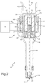
- each electromagnetic fuel injector 4 substantially has a cylindrical symmetry around a longitudinal axis 10 and is controlled so as to inject fuel from an injection nozzle 11.
- the electromagnetic injector 4 comprises a support body 12, which has a cylindrical tubular shape with a variable cross-section along the longitudinal axis 10 and comprises a feeding channel 13 extending along the entire length of the support body 12 so as to feed the fuel under pressure to the injection nozzle 11.
- the support body 12 supports, in the area of an upper portion of its, an electromagnetic actuator 14 and, in the area of a lower portion of its, an injection valve 15, which delimits the feeding channel 13 at the bottom; in use, the injection valve 15 is operated by the electromagnetic actuator 14 so as to adjust the flow of fuel through the injection jet 11, which is obtained in the area of the injection valve 15.
- the electromagnetic actuator 14 comprises a coil 16, which is arranged on the outside around the tubular body 12 and is enclosed in a toroidal casing 17 made of a plastic material, and a fixed magnetic pole 18, which is made of a ferromagnetic material and is arranged inside the tubular body 12 in the area of the coil 16. Furthermore, the electromagnetic actuator 15 comprises a movable armature 19, which has a cylindrical shape, is made of a ferromagnetic material and is designed to be magnetically attracted by the magnetic pole 18 when the coil 16 is energized (i.e. a current flows through it).
- the electromagnetic actuator 15 comprises a tubular magnetic armature 20, which is made of a ferromagnetic material, is arranged on the outside of the tubular body 12 and comprises an annular seat 21 to house, on the inside, the coil 16, and a magnetic washer 22 with an annular shape, which is made of a ferromagnetic material and is arranged above the col 16 to guide the closing of the magnetic flux around the coil 16.
- the movable armature 19 is part of a movable equipment, which comprises, furthermore, a shutter or plunger 23 having an upper portion integral to the movable armature 19 and a lower portion cooperating with a valve seat 24) of the injection valve 15 so as to adjust, in a known manner, the flow of fuel towards the injection nozzle 11.
- the plunger 23 ends with a shutting head with a substantially spherical shape, which is designed to rest against the valve seat in a sealing manner.
- the magnetic pole 18 is perforated at the centre and has a central through hole 25, which partially houses a closing spring 26, which pushes the movable armature 19 towards a closed position of the injection valve 15.
- a striker element 27 which keeps the closing spring 26 compressed against the movable armature 19.
- the movable armature 19 In use, when the electromagnetic actuator 14 is deenergized, the movable armature 19 is not attracted by the magnetic pole 18 and the elastic force of the closing spring 26 pushes the movable armature 19 together with the plunger 23 (i.e. the movable equipment) downwards up to a lower limit position, in which the shutting head of the plunger 23 is pressed against the valve seat 24 of the injection valve 15 insulating the injection nozzle 11 from the fuel under pressure.
- the electromagnetic actuator 14 When the electromagnetic actuator 14 is energized, the movable armature 19 is magnetically attracted by the magnetic pole 18 against the elastic force of the closing spring 26 and the movable armature 19 together with the plunger 23 (i.e.
- the movable equipment move upwards, due to the magnetic attraction exerted by the magnetic pole 18, up to the an upper limit position, in which the movable armature 19 strikes against the magnetic pole 18 and the shutting head of the plunger 23 is lifted relative to the valve seat 24 of the injection valve 15 allowing the fuel under pressure to flow through the injection nozzle 11.
- the coil 16 of the electromagnetic actuator 14 of each electromagnetic fuel injector 4 is powered by the electronic control unit 9, which applies, to the terminals 100 and 101 (namely to the ends) of the coil 16, a voltage v, which is variable in time and determines the circulation, through the coil 16, of a current i, which is variable in time.
- the terminal 100 of the coil 16 is the high-voltage terminal and can be connected to the power supply voltage through at least one first control transistor of the electronic control unit 9; on the other hand, the terminal 101 of the coil 16 is the low-voltage terminal and can be connected to the electric ground through at least one second control transistor of the electronic control unit 9.
- the law of injection i.e. the law linking the injection time T INJ , or control time, to the injected fuel quantity Q and represented by the injection time T INJ - injected fuel quantity Q curve
- each electromagnetic fuel injector 4 can be divided into three areas: an initial area A of failed opening, in which the injection time T INJ is too small and, hence, the energy delivered to the coil 16 of the electromagnetic actuator 14 produces a force that is not sufficient to overcome the force of the closing spring 26 and the plunger 23 remains still in the closed position of the injection valve 15; a ballistic area B, in which the plunger 23 moves from the closed position of the injection valve 15 towards a complete open position (in which the movable armature 19, which is integral to the plunger 23, strikes against the fixed magnetic pole 18), but cannot reach the complete open position and, hence, returns to the closed position before having reached the complete open position; and a linear area C, in which the plunger 23 moves from the closed position of the injection valve 15 to the complete open position, which is maintained for a given amount
- the diagram of figure 4 shows the evolution over time of some physical quantities of an electromagnetic fuel injector 4, which is controlled so as to inject fuel in the ballistic operating area B.
- the injection time T INJ is reduced (by approximately 0.15 - 0.30 ms depending on the pressure of the fuel and on the type of injector) and, hence, due the electromagnetic attraction generated by the electromagnetic actuator 14, the plunger 23 (together with the movable armature 19) moves from the closed position of the injection valve 15 towards a complete open position (in which the movable armature 19, which is integral to the plunger 23, strikes against the fixed magnetic pole 18), which, though, is not reached, as the electromagnetic actuator 14 is turned off before the plunger 23 (together with the movable armature 19) can reach the complete open position of the injection valve 15; as a consequence, when the plunger 23 is still "flying" (i.e.
- the electromagnetic actuator 14 is turned off and the thrust generated by the closing spring 26 interrupts the movement of the plunger 23 towards the complete open position of the injection valve 15, thus moving the plunger 23 in an opposite direction until the plunger 23 reaches the initial closed position of the injection valve 15.
- the logic control command c of the electromagnetic injector 4 involves activating (energizing) the electromagnetic actuator 14 in an instant t 1 (shifting of the logic control command c from the OFF state to the ON state) and deactivating (de-energizing) the electromagnetic actuator 14 in an instant t 3 (shifting of the logic control command from the ON state to the OFF state).
- the injection time T INJ is equal to the time interval elapsing between the instants t 1 and t 3 and is small; as a consequence, the electromagnetic fuel injector 4 operates in the ballistic operating area B.
- the coil 16 of the electromagnetic actuator 14 is energized and, hence, starts producing a drive force, which counters the force of the closing spring 26; when the drive force generated by the coil 16 of the electromagnetic actuator 14 exceeds the force of the closing spring 26, namely in the instant t 2 , the position p of the plunger 23 (which is integral to the movable armature 19) starts changing from the closed position of the injection valve 15 (indicated with "Close” in figure 4 ) to the complete open position of the injection valve 15 (indicated with "Open” in figure 4 ); in other words, the injection valve 15 starts opening in the instant t 2 and the time elapsing between the instants t 1 and t 2 defines the opening time T O (namely, the time elapsing between the instant t 1 in which the energization of the electromagnetic actuator 14 starts and the instant t 2 in which the injection valve 15 actually starts opening).
- the opening time To establishes the boundary between the initial area A of failed opening and the ballistic operating area B: indeed, if the injection time T INJ is smaller than the opening time To, the injection valve 15 does not open and, hence, we are in the initial area A of failed opening, whereas, if the injection time T INJ is greater than the opening time T O , the injection valve 15 opens and, hence, we are in the ballistic operating area B (or, if the injection time T INJ is long enough, we are in the linear area C).
- the position p of the plunger 23 still has not reached the complete open position of the injection valve 15 and, due to the end of the logic control command c of the electromagnetic injector 4, it goes back to the closed position of the injection valve 15, which is reached in the instant t 5 (i.e. in the moment in which the shutting head of the plunger 23 rests against the valve seat of the injection valve 15 is a sealing manner).
- the instant t 4 is identified, in which the current i flowing through the coil 16 is cancelled (namely, reaches a zero value) and in which the voltage v applied to the ends of the coil 16 starts decreasing (in absolute value), moving towards a zero value.
- the closing time Tc is the time interval elapsing between the instants t 3 and t 5 , i.e. the time interval elapsing between the end of the logic control command c of the electromagnetic injector 4 and the closing of the electromagnetic injector 4.
- the closing time T C is also equal to the sum of a zeroing time T Z , which is comprised between the instants t 3 and t 4 and in which the current i flowing through the coil 16 is still present (and, hence, the electromagnetic actuator 14 still produces a magnetic attraction force for the movable armature 19), and a flying time T F , which is comprised between the instants t 4 and t 5 and in which the current i flowing through the coil 16 is equal to zero and, hence, the sole elastic force generated by the closing spring 26 acts upon the movable armature 19.
- the voltage v applied to the ends of the coil 16 of the electromagnetic actuator 14 of the electromagnetic injector 4 is caused to increase until it reaches a positive turning-on peak, which serves the purpose of quickly increasing the current i flowing through the coil 16; at the end of the turning-on peak, the voltage v applied to the ends of the coil 16 is controlled according to the "chopper" technique, which involves cyclically changing the voltage v between a positive value and a zero value so as to keep the current i in the neighbourhood of a desired maintaining value (for the sake of simplicity, the cyclic change in the voltage v is not shown in figure 4 ).
- the voltage v applied to the ends of the coil 16 is caused to quickly decrease until it reaches a negative turning-off peak, which serves the purpose of quickly cancelling the current i flowing through the coil 16.
- the residual voltage v runs down with an exponential law until it is cancelled and, during this voltage v cancellation step, the electromagnetic injector 4 closes (in the instant t 4 , in which the plunger 23 reaches the closed position of the injection valve 15); indeed, the plunger 23 starts the closing travel towards the closed position of the injection valve 15 only when the force of the closing spring 26 exceeds the electromagnetic attraction force which is generated by the electromagnetic actuator 14 and is proportional to the current i (i.e. becomes equal to zero when the current i reaches a zero value).
- the diagram of figure 5 shows the evolution over time of some physical quantities of an electromagnetic fuel injector 4, which is controlled with an injection time T INJ (which, in turn, is equal to the time interval elapsing between the beginning instant t 1 of the injection and the end instant t 3 of the injection) that is so small that it cannot reach the opening of the injection valve 15 (namely, an injection time T INJ which belongs the initial area A of failed opening and is smaller than the opening time To).
- the injection time T INJ is smaller than the opening time To and, hence, is so small (around 0.05 - 0.15 ms) that the electromagnetic attraction generated by the electromagnetic actuator 14 upon the plunger 23 (together with the movable armature 19) always remains smaller than the elastic force generated by the closing spring 26.
- the logic control command c of the electromagnetic injector 4 involves activating (energizing) the electromagnetic actuator 14 in an instant t 1 (shifting of the logic control command c from the OFF state to the ON state) and deactivating (de-energizing) the electromagnetic actuator 14 in an instant t 3 (shifting of the logic control command from the ON state to the OFF state).
- the injection time T INJ is equal to the time interval elapsing between the instants t 1 and t 3 and is small; as a consequence, the electromagnetic fuel injector 4 operates in the initial area A of failed opening.
- the coil 16 of the electromagnetic actuator 14 is energized and, hence, starts producing a drive force, which counters the force of the closing spring 26; however, the drive force generated by the electromagnetic actuator 14 never manages to overcome (exceed) the elastic force generated by the closing spring 26 and, therefore, the plunger 23 (which is integral to the movable armature 19) never moves from the closed position of the injection valve 15 (indicated with "Close” in figure 5 ).
- the current i flowing through the coil 16 is cancelled (namely, reaches a zero value) and the voltage v applied to the ends of the coil 16 starts decreasing (in absolute value), approaching a zero value. Once the current i has reached a zero value in the instant t 4 , the residual voltage v runs down with an exponential law until it is cancelled.
- the electronic control unit 9 applies, to the coil 16 of the electromagnetic actuator 14, a positive voltage v so as to cause an actuation electric current i to circulate through the coil 16, said actuation electric current i determining the opening of the injection valve 15, and, in the end instant t 3 of the injection, the electronic control unit 9 applies, to the coil 16 of the electromagnetic actuator 14, a negative voltage v to cancel (in the instant t 4 ) the actuation electric current i circulating through the coil 16.
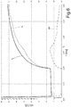
- the electronic control unit 9 detects (measures) a voltage actuation time development v 1 (shown in figure 6 ) at at least one end (i.e. one terminal 100 or 101) of the coil 16 of the electromagnetic actuator 14 after the cancellation of the actuation electric current i circulating through the coil 16 (i.e. after the instant t 4 ) and until the cancellation of the voltage v. Subsequently, the electronic control unit 9 compares the voltage actuation time development v 1 with a voltage comparison time development v 2 previously determined in the ways described below. Finally, the electronic control unit 9 determines the closing instant t 5 of the electromagnetic fuel injector 4 based on the comparison between the voltage actuation time development v 1 and the voltage comparison time development v 2 .
- the electronic control unit 9 carries out beforehand, namely before determining the closing instant t 5 of the electromagnetic injector 4, a test on the electromagnetic injector 4, which is controlled with an injection time T INJ (which, in turn, is equal to the time interval elapsing between the beginning instant t 1 of the injection and the end instant t 3 of the injection) that is so small that it cannot reach the opening of the injection valve 15 (namely, an injection time T INJ which belongs the initial area A of failed opening and is smaller than the opening time T O ), as shown in figure 5 .
- an injection time T INJ which belongs the initial area A of failed opening and is smaller than the opening time T O
- the electronic control unit 9 applies, in a beginning instant t 1 of the test, a positive voltage v to the coil 16 of the electromagnetic actuator 14 so as to cause a test electric current i to circulate through the coil 16, said test electric current i not determining the opening of the injection valve 15, and the electronic control unit 9 applies, in an end instant t 3 of the test, a negative voltage v to the coil 16 of the electromagnetic actuator 14 so as to cancel the test electric current i circulating through the coil 16 without determining the opening of the injection valve 15.
- the electronic control unit 9 detects (measures) a voltage comparison time development v 2 (shown in figure 6 ) at at least one end (namely, one terminal 100 or 101) of the coil 16 of the electromagnetic actuator 14 after the cancellation of the test electric current i circulating through the coil 16 without determining the opening of the injection valve 15; in other words, the electronic control unit 9 identifies the voltage comparison time development v 2 as time development after the cancellation of the test electric current i circulating through the coil 16 without determining the opening of the injection valve 15.
- the electronic control unit 9 is provided with a hardware anti-aliasing filter (namely, a physical anti-aliasing filter acting upon the analogue signal before the digitization), which acts upon the measurement of the voltage v at at least one end (namely, one terminal 100 or 101) of the coil 16 of the electromagnetic actuator 14.
- the anti-aliasing filter is an analogue signal used before the sampling of the signal of the voltage v, so as to narrow the band of the signal in order to approximately fulfil the Nyquist-Shannon sampling theorem.
- the movable armature 19 which is integral to the plunger 23, very quickly changes its law of motion (i.e. it almost instantly shifts from a relatively high speed to a zero speed and, if necessary, it could even make a small bounce which reverses the speed direction) and this basically instantaneous change in the law of motion of the movable armature 19 produces a perturbation in the magnetic field linked to the coil 16 and, hence, also determines a perturbation of the voltage v at the ends of the coil 16.
- the electronic control unit 9 synchronizes the voltage actuation time development v 1 with the voltage comparison time development v 2 by aligning, in a time-wise manner, a first instant t 4 in which the actuation electric current i circulating through the coil 16 is cancelled with a second instant t 4 in which the test electric current i circulating through the coil 16 is cancelled.
- the electronic control unit 9 calculates (by means of a simple subtraction) a voltage difference ⁇ v (shown in figure 6 ) between the voltage actuation time development v 1 and the voltage comparison time development v 2 and determines the closing instant t 5 of the electromagnetic injector 4 based on the voltage difference ⁇ v.
- the electronic control unit 9 preferably, though not necessarily, applies a low-pass filter, in particular a sliding-window filter, to the voltage difference ⁇ v so as to eliminate the high-frequency noise.
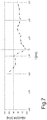
- the electronic control unit 9 calculates a first time derivative d ⁇ v/dt of the voltage difference ⁇ v (shown in figure 7 ) and, therefore, determines the closing instant t 5 of the electromagnetic injector 4 based on the first time derivative d ⁇ v/dt of the voltage difference ⁇ v.
- the electronic control unit 9 determines an absolute minimum of the first time derivative d ⁇ v/dt of the voltage difference ⁇ v and identifies the closing instant t 5 of the electromagnetic injector 4 in the area of the absolute minimum of the first time derivative d ⁇ v/dt of the voltage difference ⁇ v (as shown in figure 7 ).
- a predetermined time advance is applied, which makes up for the phase delays introduced by all the filters to which the voltage v is subjected; in other words, the closing instant t 5 determined as described above is advanced by means of a predefined time interval in order to take into account the phase delays introduced by all the filters to which the voltage v at the ends of the coil 16 is subjected.
- the electronic control unit 9 recognizes the presence of a closing of the electromagnetic injector 4 only if the voltage difference ⁇ v, in absolute value, exceeds a first threshold, and/or recognizes the presence of a closing of the electromagnetic injector 4 only if the first time derivative d ⁇ v/dt of the voltage difference ⁇ v exceeds, in absolute vale, a second threshold. In other words, the electronic control unit 9 recognizes the absence of a closing of the electromagnetic injector 4 only if the voltage difference ⁇ v, in absolute value, is below the first threshold and/or if the first time derivative d ⁇ v/dt of the voltage difference ⁇ v, in absolute vale, is below the second threshold.
- the electronic control unit 9 establishes that the voltage actuation time development v 1 is completely similar to the voltage comparison time development v 2 and, hence, there was no closing of the electromagnetic injector 4 (namely, a closing of the electromagnetic injector 4 is absent).
- the electronic control unit 9 calculates a maximum value of the first time derivative d ⁇ v/dt of the voltage difference ⁇ v, identifies the presence of a closing of the electromagnetic injector 4 if the maximum value of the first time derivative d ⁇ v/dt of the voltage difference ⁇ v exceeds, in absolute value, the second threshold, and identifies the absence of a closing of the electromagnetic injector 4 if the maximum value of the first time derivative d ⁇ v/dt of the voltage difference ⁇ v is, in absolute value, below the second threshold.
- the electronic control unit 9 calculates a maximum value of the voltage difference ⁇ v, identifies the presence of a closing of the electromagnetic injector 4 only if the maximum value of the voltage difference ⁇ v exceeds, in absolute value, the first threshold, and identifies the absence of a closing of the electromagnetic injector 4 if the maximum value of the voltage difference ⁇ v is, in absolute value, below the first threshold.
- the test to detect the voltage comparison time development v 2 is carried out immediately before each fuel injection, so that a voltage comparison time development v 2 is used to determine the closing instant t 5 of the electromagnetic injector 4 of one single corresponding injection taking place immediately after.
- a specific voltage comparison time development v 2 is (immediately) determined and then, right after that, the fuel injection is carried out and the specific voltage comparison time development v 2 is used to determine the closing instant t 5 .
- the test to detect the voltage comparison time development v 2 is carried out every now and then, so that a voltage comparison time development v 2 is used to determine the closing instant t 5 of the electromagnetic fuel injector 4 of different injections.
- a voltage comparison time development v 2 applies to (can be used for) different injections taking place in different moments.
- different voltage comparison time developments v 2 can be stored upon variation of the pressure of the fuel in the common-rail 5.
- different voltage comparison time developments v 2 are detected and then statistically processed and periodically updated.
- the voltage v is measured by the electronic control uni 9 between the two terminals 100 and 101 of the coil 16 when the first and the second voltage time developments v 1 and v 2 are detected; this solution involves a differential measurement, which is more complicated because it requires the use of two distinct voltage sensors connected to the two terminals 100 and 101 of the coil 16.
- the voltage v is measured by the electronic control unit 9 between the low-voltage terminal 101 of the coil 16 and an electric ground when the voltage time developments v 1 and v 2 are detected; this solution is simpler because it involves the use of one single voltage sensor connected to the low-voltage terminal 101 of the coil 16.
- the electronic control unit 9 decides the values of the injection time T INJ for which the corresponding closing time must be known. It is generally unlikely that, in the short term, the engine control requires an electromagnetic injector 4 to be controlled exactly with an injection time T INJ for which the corresponding closing time must be known; as a consequence, the electronic control unit 9 "forces" the situation making sure that, in any case, (at least) one injection is carried out, which has an injection time T INJ for which the corresponding closing time T C must be known.
- the electronic control unit 9 establishes a rotation speed objective and a torque objective to be generated for an internal combustion engine 2 and, then, determines a total quantity Q of fuel to be injected based on the rotation speed objective and on the torque objective to be generated; subsequently, the electronic control unit 9 controls the electromagnetic fuel injector 4 using a first injection time T INJ1 for which a corresponding closing time T C is to be determined and determines a first partial fuel quantity Q 1 which is actually injected using the first injection time T INJ1 .
- the electronic control unit 9 determines a second partial fuel quantity Q 2 equal to the difference between the total fuel quantity Q and the first partial fuel quantity Q 1 and determines a second injection time T INJ2 based on the second partial fuel quantity Q 2 so as to exactly inject the second partial fuel quantity Q 2 ; finally, the electronic control unit 9 controls the electromagnetic fuel injector 4 using the second injection time T INJ2 .
- the electronic control unit 9 chooses the first injection time T INJ1 so that the difference between the total fuel quantity Q and the first partial fuel quantity Q 1 exceeds a predetermined threshold value (namely is great enough to allow the second partial fuel quantity Q 2 to be injected with an acceptable precision).
- the method described above to determine the closing instant t 5 of the electromagnetic injector 4 applies in any operating condition of the electromagnetic injector 4, i.e. both when the electromagnetic injector 4 operates in the ballistic area B, in which, in the end instant t 3 of the injection, the plunger 23 still has not reached the complete open position of the injection valve 15, and when the electromagnetic injector 4 operates in the linear area C, in which, in the end instant t 3 of the injection, the plunger 23 has reached the complete open position of the injection valve 15.
- knowing the closing instant t 5 of the electromagnetic injector 4 is particularly useful when the electromagnetic injector 4 operates in the ballistic area B, in which the injection feature of the electromagnetic injector 4 is strongly nonlinear and dispersed, whereas it generally is not very useful when the electromagnetic injector 4 operates in the linear area C, in which the injection feature of the electromagnetic injector 4 is linear and not very dispersed.
- the electronic control unit 9 controls the electromagnetic fuel injector 4 using a series of progressively increasing energization times T INJ of the electromagnetic actuator 14 and determines, for each control of the electromagnetic injector 4, the presence or the absence of a closing of the injection valve 15 (i.e. whether the injection valve 15 actually opened or did not open) according to the procedure described above; finally, the electronic control unit 9 identifies the opening time To equal to an intermediate value between the last energization time T INJ of the electromagnetic actuator 14 for which the absence of a closing of the injection valve 15 was determined and the first energization time T INJ of the electromagnetic actuator 14 for which the presence of a closing of the injection valve 15 was determined.
- control unit 9 establishes an expected value of the opening time To (for example, equal to a nominal value or equal to the last, previously estimated value) and centres the series of progressively increasing energization times T INJ of the electromagnetic actuator 14 on the expected value of the opening time T O .
- the electronic control unit 9 establishes a time resolution in determining the presence or the absence of a closing of the injection valve 15 and, then, increases the energization times T INJ of the electromagnetic actuator 14 of the series of progressively increasing energization times T INJ of the electromagnetic actuator 14 with an increase which is equal to the time resolution in determining the presence or the absence of a closing of the injection valve 15.
- the resolution in the ability, in the execution of a measurement, to detect small variations of the physical quantity being examined (namely, the ability to detect whether an opening of the injection valve 15 took place or did not take place).
- the presence or the absence of a closing of the injection valve 15 i.e. whether the injection valve 15 actually opened or did not open
- the presence or the absence of a closing of the injection valve 15 namely, whether the injection valve 15 actually opened or did not open
- the presence or the absence of a closing of the injection valve 15 namely, whether the injection valve 15 actually opened or did not open
- the control of an electromagnetic injector 4 can be determined with different procedures from the one described above.
- the method described above to determine a closing instant of an electromagnetic fuel injector 4 allows the actual closing instant of an electromagnetic injector 4 to be identified with a great precision. This result is obtained thanks to the fact that the "behaviour" of an electromagnetic injector 4 in the moment of the closing of the injection valve 15 (namely, the voltage actuation time development v 1 ) is compared with "itself", i.e.
- an electromagnetic fuel injector 4 can also be used in the ballistic area to inject very small quantities of fuel (about 1 milligram), ensuring at the same time an adequate precision of the injection.
- the method described above to determine a closing instant of an electromagnetic fuel injector 4 is simple and economic to be implemented even in an existing electronic control unit 9, because it does not require additional hardware to be added to the hardware already normally present in fuel injection systems, does not need a significant calculation ability and does not involve a large memory space.
- the method described above to determine the opening time To allows the actual opening time To of an electromagnetic injector 4 to be identified with a good precision. Knowing the actual opening time TO of an electromagnetic injector 4 is important because the opening time TO establishes, in the law of injection, the boundary between the initial area A of failed opening and the ballistic operating area B: indeed, if the injection time T INJ is smaller than the opening time T O , the injection valve 15 does not open and, hence, we are in the initial area A of failed opening, whereas, if the injection time T INJ is greater than the opening time To, the injection valve 15 opens and, hence, we are in the ballistic operating area B (or, if the injection time T INJ is long enough, we are in the linear area C). Therefore, knowing the actual opening time To of an electromagnetic injector 4 leads to better knowing of the corresponding law of injection and, hence, allows the electromagnetic injector 4 to be controlled with a greater precision.
- the method described above to determine the opening time To of an electromagnetic fuel injector 4 is simple and economic to be implemented even in an existing electronic control unit 9, because it does not require additional hardware to be added to the hardware already normally present in fuel injection systems, does not need a significant calculation ability and does not involve a large memory space.
Landscapes
- Engineering & Computer Science (AREA)
- Chemical & Material Sciences (AREA)
- Combustion & Propulsion (AREA)
- Mechanical Engineering (AREA)
- General Engineering & Computer Science (AREA)
- Physics & Mathematics (AREA)
- Electromagnetism (AREA)
- Fuel-Injection Apparatus (AREA)
- Electrical Control Of Air Or Fuel Supplied To Internal-Combustion Engine (AREA)
- Magnetically Actuated Valves (AREA)
Claims (9)
- Verfahren zum Bestimmen einer Öffnungszeit (TO) einer elektromagnetischen Kraftstoffeinspritzvorrichtung (4), die einen beweglichen Kolben (23), der sich zwischen einer Schließposition und einer Öffnungsposition bewegt, um ein Einspritzventil (15) zu schließen und zu öffnen, und einen elektromagnetischen Aktor (14) umfasst, der mit einer Spule (16) versehen ist und dazu ausgelegt ist, den Kolben (23) zwischen der Schließposition und der Öffnungsposition zu bewegen; wobei das Verfahren die Schritte umfasst:Ansteuern der elektromagnetischen Kraftstoffeinspritzvorrichtung (4) unter Verwendung einer Reihe von progressiv ansteigenden Erregungszeiten (TINJ) des elektromagnetischen Aktors (14);Feststellen des Vorhandenseins oder des Fehlens eines Schließens des Einspritzventils (15) für jede Ansteuerung der elektromagnetischen Einspritzvorrichtung (4); undErkennen der Öffnungszeit (TO) gleich einem Zwischenwert zwischen der letzten Erregungszeit (TINJ) des elektromagnetischen Aktors (14), für die das Fehlen eines Schließens des Einspritzventils (15) festgestellt wurde, und der ersten Erregungszeit (TINJ) des elektromagnetischen Aktors (14), für die das Vorhandensein eines Schließens des Einspritzventils (15) festgestellt wurde;wobei das Verfahren dadurch gekennzeichnet ist, dass der Schritt des Feststellens des Vorhandenseins oder des Fehlens eines Schließens des Einspritzventils (15) für jede Ansteuerung der elektromagnetischen Einspritzvorrichtung (4) die weiteren Schritte umfasst:Anlegen einer positiven Spannung (v) an die Spule (16) des elektromagnetischen Aktors (14) in einem Anfangszeitpunkt (t1) eines Prüfvorgangs, um zu bewirken, dass ein elektrischer Prüfstrom (i) durch die Spule (16) zirkuliert, wobei der elektrische Prüfstrom (i) sicher nicht das Öffnen des Einspritzventils (15) veranlasst;Anlegen einer negativen Spannung (v) an die Spule (16) des elektromagnetischen Aktors (14) in einem Endzeitpunkt (t3) des Prüfvorgangs, um den elektrischen Prüfstrom (i) zu löschen;Erfassen eines Vergleich-Spannungszeitverlaufs (v2) an wenigstens einem Ende der Spule (16) des elektromagnetischen Aktors (14) nach dem Löschen des elektrischen Prüfstroms (i);Anlegen einer positiven Spannung (V) an die Spule (16) des elektromagnetischen Aktors (14) in einem Anfangszeitpunkt (t1) einer Erregung des elektromagnetischen Aktors (14), um zu bewirken, dass ein elektrischer Betätigungsstrom (i) durch die Spule (16) zirkuliert, wobei der elektrische Betätigungsstrom (i) möglicherweise die Öffnung des Einspritzventils (15) veranlasst;Anlegen einer negativen Spannung (v) an die Spule (16) des elektromagnetischen Aktors (14) in einem Endzeitpunkt (t2) der Erregung des elektromagnetischen Aktors (14), um den elektrischen Betätigungsstrom (i) zu löschen;Erfassen eines Betätigung-Spannungszeitverlaufs (v1) an wenigstens einem Ende der Spule (16) des elektromagnetischen Aktors (14) nach dem Löschen des elektrischen Betätigungsstroms (i);Berechnen einer Spannungsdifferenz (Δv) zwischen dem Betätigung-Spannungszeitverlauf (v1) und dem Vergleich-Spannungszeitverlauf (v2);Berechnen einer ersten zeitlichen Ableitung (dΔv/dt) der Spannungsdifferenz (Δv);Berechnen eines Maximalwertes der ersten zeitlichen Ableitung (dΔv/dt) der Spannungsdifferenz (Δv);Erkennen des Vorhandenseins eines Schließens der elektromagnetischen Einspritzvorrichtung (4) nur dann, wenn der Maximalwert der ersten Zeitableitung (dΔv/dt) der Spannungsdifferenz (Δv) im Absolutwert einen ersten Schwellenwert überschreitet; undErkennen des Fehlens eines Schließens der elektromagnetischen Einspritzvorrichtung (4), wenn der Maximalwert der ersten zeitlichen Ableitung (dΔv/dt) der Spannungsdifferenz (Δv) im Absolutwert unter dem ersten Schwellenwert liegt.
- Verfahren nach Anspruch 1, die weiteren Schritte umfassend:Festlegen eines Erwartungswertes der Öffnungszeit (TO);
undZentrieren der Reihe von progressiv ansteigenden Erregungszeiten (TINJ) des elektromagnetischen Aktors (14) auf den Erwartungswert der Öffnungszeit (TO). - Verfahren nach Anspruch 1 oder 2, die weiteren Schritte umfassend:Festlegen einer Zeitauflösung bei der Feststellung des Vorhandenseins oder des Fehlens eines Schließens des Einspritzventils (15); undErhöhen der Erregungszeiten (TINJ) des elektromagnetischen Aktors (14) in der Reihe von progressiv ansteigenden Erregungszeiten (TINJ) des elektromagnetischen Aktors (14) mit einer Erhöhung, die gleich der Zeitauflösung bei der Feststellung des Vorhandenseins oder des Fehlens eines Schließens des Einspritzventils (15) ist.
- Verfahren nach Anspruch 1, 2 oder 3, umfassend den weiteren Schritt des Synchronisierens des Betätigung-Spannungszeitverlaufs (v1) mit dem Vergleich-Spannungszeitverlauf (v2) durch zeitliches Angleichen eines ersten Zeitpunkts (t4), in dem der elektrische Betätigungsstrom (i) gelöscht ist, an einen zweiten Zeitpunkt (t4), in dem der elektrische Prüfstrom (i) gelöscht ist.
- Verfahren nach einem der Ansprüche 1 bis 4, die weiteren Schritte umfassend:Berechnen eines Maximalwertes der Spannungsdifferenz (Δv) ;Erkennen des Vorhandensein eines Schließens der elektromagnetischen Einspritzvorrichtung (4) nur dann, wenn der Maximalwert der Spannungsdifferenz (Δv) im Absolutwert einen zweiten Schwellenwert überschreitet; undErkennen des Fehlens eines Schließens der elektromagnetischen Einspritzvorrichtung (4), wenn der Maximalwert der Spannungsdifferenz (Δv) im Absolutwert unter dem zweiten Schwellenwert liegt.
- Verfahren nach einem der Ansprüche 1 bis 5, den weiteren Schritt des Anwendens eines Tiefpassfilters, insbesondere eines Gleitfensterfilters, auf die Spannungsdifferenz (Δv) umfassend.
- Verfahren nach einem der Ansprüche 1 bis 6, den weiteren Schritt des Anwendens eines Anti-Aliasing-Filters auf die Spannung (v) umfassend, wenn die Spannungszeitverläufe (v1, v2) erfasst werden.
- Verfahren nach einem der Ansprüche 1 bis 7, wobei:die Spule (16) des elektromagnetischen Aktors (14) einen Hochspannungsanschluss (100) und einen Niederspannungsanschluss (101) aufweist; unddie Spannung (v) zwischen den beiden Anschlüssen (100, 101) der Spule (16) gemessen wird, wenn der erste und der zweite Spannungszeitverlauf (v1, v2) erfasst werden.
- Verfahren nach einem der Ansprüche 1 bis 7, wobei:die Spule (16) des elektromagnetischen Aktors (14) einen Hochspannungsanschluss (100) und einen Niederspannungsanschluss (101) aufweist; unddie Spannung (v) zwischen dem Niederspannungsanschluss (101) der Spule (16) und einer elektrischen Masse gemessen wird, wenn der erste und der zweite Spannungszeitverlauf (v1, v2) erfasst werden.
Applications Claiming Priority (1)
| Application Number | Priority Date | Filing Date | Title |
|---|---|---|---|
| IT102018000005765A IT201800005765A1 (it) | 2018-05-28 | 2018-05-28 | Metodo per determinare un tempo di apertura di un iniettore elettromagnetico di carburante |
Publications (2)
| Publication Number | Publication Date |
|---|---|
| EP3575583A1 EP3575583A1 (de) | 2019-12-04 |
| EP3575583B1 true EP3575583B1 (de) | 2021-06-30 |
Family
ID=63244871
Family Applications (1)
| Application Number | Title | Priority Date | Filing Date |
|---|---|---|---|
| EP19177134.4A Active EP3575583B1 (de) | 2018-05-28 | 2019-05-28 | Verfahren zur bestimmung einer öffnungszeit eines elektromagnetischen kraftstoffeinspritzers |
Country Status (5)
| Country | Link |
|---|---|
| US (1) | US10830172B2 (de) |
| EP (1) | EP3575583B1 (de) |
| JP (1) | JP7330759B2 (de) |
| CN (1) | CN110541770B (de) |
| IT (1) | IT201800005765A1 (de) |
Families Citing this family (3)
| Publication number | Priority date | Publication date | Assignee | Title |
|---|---|---|---|---|
| IT201800005760A1 (it) * | 2018-05-28 | 2019-11-28 | Metodo per determinare un istante di chiusura di un iniettore elettromagnetico di carburante | |
| WO2020110555A1 (ja) * | 2018-11-29 | 2020-06-04 | 日立オートモティブシステムズ株式会社 | 内燃機関用制御装置 |
| IT202000004003A1 (it) | 2020-02-26 | 2021-08-26 | Marelli Europe Spa | Metodo di verifica della ripetibilita' dell'iniezione in un iniettore elettromagnetico di carburante e corrispondente banco di prova |
Family Cites Families (14)
| Publication number | Priority date | Publication date | Assignee | Title |
|---|---|---|---|---|
| US6848626B2 (en) * | 2001-03-15 | 2005-02-01 | Siemens Vdo Automotive Corporation | End of valve motion detection for a spool control valve |
| ITTO20040512A1 (it) | 2004-07-23 | 2004-10-23 | Magneti Marelli Powertrain Spa | Iniettore di carburante provvisto di spillo ad elevata flessibilita' |
| JP4428201B2 (ja) * | 2004-11-01 | 2010-03-10 | 株式会社デンソー | 蓄圧式燃料噴射装置 |
| EP1705355B1 (de) * | 2005-03-25 | 2008-02-20 | Delphi Technologies, Inc. | Verfahren zur Bestimmung von Parametern eines Einspritzsystems |
| DE102006059070A1 (de) * | 2006-12-14 | 2008-06-19 | Robert Bosch Gmbh | Kraftstoffeinspritzsystem und Verfahren zum Ermitteln eines Nadelhubanschlags in einem Kraftstoffeinspritzventil |
| DE102009045307A1 (de) * | 2009-10-02 | 2011-04-07 | Robert Bosch Gmbh | Verfahren und Steuergerät zum Betreiben eines Ventils |
| IT1399311B1 (it) * | 2010-04-07 | 2013-04-16 | Magneti Marelli Spa | Metodo per determinare l'istante di chiusura di un iniettore elettromagnetico di carburante |
| IT1399312B1 (it) * | 2010-04-07 | 2013-04-16 | Magneti Marelli Spa | Metodo di controllo di un iniettore elettromagnetico di carburante |
| DE102010018290B4 (de) * | 2010-04-26 | 2016-03-31 | Continental Automotive Gmbh | Elektrische Ansteuerung eines Ventils basierend auf einer Kenntnis des Schließzeitpunkts des Ventils |
| DE102010022109B3 (de) * | 2010-05-31 | 2011-09-29 | Continental Automotive Gmbh | Bestimmung des Schließzeitpunkts eines Einspritzventils basierend auf einer Auswertung der Ansteuerspannung unter Verwendung eines adaptierten Referenzspannungssignals |
| FR3023875A1 (fr) * | 2014-07-15 | 2016-01-22 | Delphi Int Operations Luxembourg Sarl | Injecteur de carburant |
| GB201421853D0 (en) * | 2014-12-09 | 2015-01-21 | Delphi International Operations Luxembourg S.�.R.L. | Fuel injection control in an internal combustion engine |
| JP6416674B2 (ja) * | 2015-03-24 | 2018-10-31 | 株式会社ケーヒン | 燃料噴射弁の制御装置 |
| IT201800005760A1 (it) * | 2018-05-28 | 2019-11-28 | Metodo per determinare un istante di chiusura di un iniettore elettromagnetico di carburante |
-
2018
- 2018-05-28 IT IT102018000005765A patent/IT201800005765A1/it unknown
-
2019
- 2019-05-28 EP EP19177134.4A patent/EP3575583B1/de active Active
- 2019-05-28 CN CN201910453606.3A patent/CN110541770B/zh active Active
- 2019-05-28 JP JP2019099296A patent/JP7330759B2/ja active Active
- 2019-05-28 US US16/423,906 patent/US10830172B2/en active Active
Also Published As
| Publication number | Publication date |
|---|---|
| JP7330759B2 (ja) | 2023-08-22 |
| US20190360423A1 (en) | 2019-11-28 |
| EP3575583A1 (de) | 2019-12-04 |
| JP2019206966A (ja) | 2019-12-05 |
| IT201800005765A1 (it) | 2019-11-28 |
| CN110541770A (zh) | 2019-12-06 |
| CN110541770B (zh) | 2022-11-08 |
| US10830172B2 (en) | 2020-11-10 |
Similar Documents
| Publication | Publication Date | Title |
|---|---|---|
| EP3575584B1 (de) | Verfahren zur bestimmung eines schliesszeitpunktes eines elektromagnetischen kraftstoffinjektors | |
| US8571821B2 (en) | Method for determining the closing time of an electromagnetic fuel injector | |
| EP2375037B1 (de) | Verfahren zur Steuerung eines elektromagnetischen Kraftstoffinjektors | |
| EP3575583B1 (de) | Verfahren zur bestimmung einer öffnungszeit eines elektromagnetischen kraftstoffeinspritzers | |
| US9435281B2 (en) | Method for reducing performance variation of an electromagnetically-activated actuator | |
| US9932947B2 (en) | Actuator with residual magnetic hysteresis reset | |
| EP2211046B1 (de) | Brennstoffeinspritzsystem mit hoher Betriebswiederholbarkeit und -stabilität für einen Verbrennungsmotor | |
| US20170179865A1 (en) | Optimum current drive for actuator control | |
| EP3781804B1 (de) | Verfahren zur steuerung eines kraftstoffeinspritzventils | |
| GB2293244A (en) | Determining the armature impact time upon de-energising a solenoid valve | |
| CN107304727B (zh) | 用于电磁启动致动器的最佳驱动信号控制的方法和装置 | |
| EP0905719B1 (de) | Steuerungsverfahren | |
| US20190010889A1 (en) | Optimization of current injection profile for solenoid injectors | |
| US9453473B2 (en) | Method for actuating a piezo injector of a fuel injection system | |
| DE102015103891B4 (de) | Aktor mit Zurücksetzen einer magnetischen Resthysterese | |
| CN105545512B (zh) | 用于对燃料喷射器的磁阀通电的方法 | |
| JP6498293B2 (ja) | 流体を噴射させるための噴射弁、噴射弁の使用方法および噴射弁の製造方法 | |
| EP3385527B1 (de) | Verfahren zur erkennung einer fehlgeschlagenen betätigung eines schaltbaren magnetventils, elektronische schaltung zur durchführung des verfahrens, pumpe und kraftfahrzeug | |
| US11608794B2 (en) | Method to estimate the temperature of an electromagnetic actuator |
Legal Events
| Date | Code | Title | Description |
|---|---|---|---|
| PUAI | Public reference made under article 153(3) epc to a published international application that has entered the european phase |
Free format text: ORIGINAL CODE: 0009012 |
|
| STAA | Information on the status of an ep patent application or granted ep patent |
Free format text: STATUS: THE APPLICATION HAS BEEN PUBLISHED |
|
| AK | Designated contracting states |
Kind code of ref document: A1 Designated state(s): AL AT BE BG CH CY CZ DE DK EE ES FI FR GB GR HR HU IE IS IT LI LT LU LV MC MK MT NL NO PL PT RO RS SE SI SK SM TR |
|
| AX | Request for extension of the european patent |
Extension state: BA ME |
|
| STAA | Information on the status of an ep patent application or granted ep patent |
Free format text: STATUS: REQUEST FOR EXAMINATION WAS MADE |
|
| 17P | Request for examination filed |
Effective date: 20200603 |
|
| GRAP | Despatch of communication of intention to grant a patent |
Free format text: ORIGINAL CODE: EPIDOSNIGR1 |
|
| STAA | Information on the status of an ep patent application or granted ep patent |
Free format text: STATUS: GRANT OF PATENT IS INTENDED |
|
| INTG | Intention to grant announced |
Effective date: 20201223 |
|
| GRAS | Grant fee paid |
Free format text: ORIGINAL CODE: EPIDOSNIGR3 |
|
| GRAA | (expected) grant |
Free format text: ORIGINAL CODE: 0009210 |
|
| STAA | Information on the status of an ep patent application or granted ep patent |
Free format text: STATUS: THE PATENT HAS BEEN GRANTED |
|
| AK | Designated contracting states |
Kind code of ref document: B1 Designated state(s): AL AT BE BG CH CY CZ DE DK EE ES FI FR GB GR HR HU IE IS IT LI LT LU LV MC MK MT NL NO PL PT RO RS SE SI SK SM TR |
|
| REG | Reference to a national code |
Ref country code: CH Ref legal event code: EP |
|
| REG | Reference to a national code |
Ref country code: AT Ref legal event code: REF Ref document number: 1406561 Country of ref document: AT Kind code of ref document: T Effective date: 20210715 |
|
| REG | Reference to a national code |
Ref country code: DE Ref legal event code: R096 Ref document number: 602019005695 Country of ref document: DE |
|
| REG | Reference to a national code |
Ref country code: IE Ref legal event code: FG4D |
|
| REG | Reference to a national code |
Ref country code: LT Ref legal event code: MG9D |
|
| PG25 | Lapsed in a contracting state [announced via postgrant information from national office to epo] |
Ref country code: FI Free format text: LAPSE BECAUSE OF FAILURE TO SUBMIT A TRANSLATION OF THE DESCRIPTION OR TO PAY THE FEE WITHIN THE PRESCRIBED TIME-LIMIT Effective date: 20210630 Ref country code: HR Free format text: LAPSE BECAUSE OF FAILURE TO SUBMIT A TRANSLATION OF THE DESCRIPTION OR TO PAY THE FEE WITHIN THE PRESCRIBED TIME-LIMIT Effective date: 20210630 Ref country code: BG Free format text: LAPSE BECAUSE OF FAILURE TO SUBMIT A TRANSLATION OF THE DESCRIPTION OR TO PAY THE FEE WITHIN THE PRESCRIBED TIME-LIMIT Effective date: 20210930 |
|
| REG | Reference to a national code |
Ref country code: NL Ref legal event code: MP Effective date: 20210630 |
|
| REG | Reference to a national code |
Ref country code: AT Ref legal event code: MK05 Ref document number: 1406561 Country of ref document: AT Kind code of ref document: T Effective date: 20210630 |
|
| PG25 | Lapsed in a contracting state [announced via postgrant information from national office to epo] |
Ref country code: GR Free format text: LAPSE BECAUSE OF FAILURE TO SUBMIT A TRANSLATION OF THE DESCRIPTION OR TO PAY THE FEE WITHIN THE PRESCRIBED TIME-LIMIT Effective date: 20211001 Ref country code: LV Free format text: LAPSE BECAUSE OF FAILURE TO SUBMIT A TRANSLATION OF THE DESCRIPTION OR TO PAY THE FEE WITHIN THE PRESCRIBED TIME-LIMIT Effective date: 20210630 Ref country code: NO Free format text: LAPSE BECAUSE OF FAILURE TO SUBMIT A TRANSLATION OF THE DESCRIPTION OR TO PAY THE FEE WITHIN THE PRESCRIBED TIME-LIMIT Effective date: 20210930 Ref country code: SE Free format text: LAPSE BECAUSE OF FAILURE TO SUBMIT A TRANSLATION OF THE DESCRIPTION OR TO PAY THE FEE WITHIN THE PRESCRIBED TIME-LIMIT Effective date: 20210630 Ref country code: RS Free format text: LAPSE BECAUSE OF FAILURE TO SUBMIT A TRANSLATION OF THE DESCRIPTION OR TO PAY THE FEE WITHIN THE PRESCRIBED TIME-LIMIT Effective date: 20210630 |
|
| PG25 | Lapsed in a contracting state [announced via postgrant information from national office to epo] |
Ref country code: AT Free format text: LAPSE BECAUSE OF FAILURE TO SUBMIT A TRANSLATION OF THE DESCRIPTION OR TO PAY THE FEE WITHIN THE PRESCRIBED TIME-LIMIT Effective date: 20210630 Ref country code: CZ Free format text: LAPSE BECAUSE OF FAILURE TO SUBMIT A TRANSLATION OF THE DESCRIPTION OR TO PAY THE FEE WITHIN THE PRESCRIBED TIME-LIMIT Effective date: 20210630 Ref country code: SM Free format text: LAPSE BECAUSE OF FAILURE TO SUBMIT A TRANSLATION OF THE DESCRIPTION OR TO PAY THE FEE WITHIN THE PRESCRIBED TIME-LIMIT Effective date: 20210630 Ref country code: PT Free format text: LAPSE BECAUSE OF FAILURE TO SUBMIT A TRANSLATION OF THE DESCRIPTION OR TO PAY THE FEE WITHIN THE PRESCRIBED TIME-LIMIT Effective date: 20211102 Ref country code: RO Free format text: LAPSE BECAUSE OF FAILURE TO SUBMIT A TRANSLATION OF THE DESCRIPTION OR TO PAY THE FEE WITHIN THE PRESCRIBED TIME-LIMIT Effective date: 20210630 Ref country code: NL Free format text: LAPSE BECAUSE OF FAILURE TO SUBMIT A TRANSLATION OF THE DESCRIPTION OR TO PAY THE FEE WITHIN THE PRESCRIBED TIME-LIMIT Effective date: 20210630 Ref country code: SK Free format text: LAPSE BECAUSE OF FAILURE TO SUBMIT A TRANSLATION OF THE DESCRIPTION OR TO PAY THE FEE WITHIN THE PRESCRIBED TIME-LIMIT Effective date: 20210630 Ref country code: EE Free format text: LAPSE BECAUSE OF FAILURE TO SUBMIT A TRANSLATION OF THE DESCRIPTION OR TO PAY THE FEE WITHIN THE PRESCRIBED TIME-LIMIT Effective date: 20210630 Ref country code: ES Free format text: LAPSE BECAUSE OF FAILURE TO SUBMIT A TRANSLATION OF THE DESCRIPTION OR TO PAY THE FEE WITHIN THE PRESCRIBED TIME-LIMIT Effective date: 20210630 |
|
| PG25 | Lapsed in a contracting state [announced via postgrant information from national office to epo] |
Ref country code: PL Free format text: LAPSE BECAUSE OF FAILURE TO SUBMIT A TRANSLATION OF THE DESCRIPTION OR TO PAY THE FEE WITHIN THE PRESCRIBED TIME-LIMIT Effective date: 20210630 |
|
| REG | Reference to a national code |
Ref country code: DE Ref legal event code: R097 Ref document number: 602019005695 Country of ref document: DE |
|
| PG25 | Lapsed in a contracting state [announced via postgrant information from national office to epo] |
Ref country code: DK Free format text: LAPSE BECAUSE OF FAILURE TO SUBMIT A TRANSLATION OF THE DESCRIPTION OR TO PAY THE FEE WITHIN THE PRESCRIBED TIME-LIMIT Effective date: 20210630 |
|
| PLBE | No opposition filed within time limit |
Free format text: ORIGINAL CODE: 0009261 |
|
| STAA | Information on the status of an ep patent application or granted ep patent |
Free format text: STATUS: NO OPPOSITION FILED WITHIN TIME LIMIT |
|
| PG25 | Lapsed in a contracting state [announced via postgrant information from national office to epo] |
Ref country code: AL Free format text: LAPSE BECAUSE OF FAILURE TO SUBMIT A TRANSLATION OF THE DESCRIPTION OR TO PAY THE FEE WITHIN THE PRESCRIBED TIME-LIMIT Effective date: 20210630 |
|
| 26N | No opposition filed |
Effective date: 20220331 |
|
| REG | Reference to a national code |
Ref country code: CH Ref legal event code: PL |
|
| REG | Reference to a national code |
Ref country code: BE Ref legal event code: MM Effective date: 20220531 |
|
| PG25 | Lapsed in a contracting state [announced via postgrant information from national office to epo] |
Ref country code: MC Free format text: LAPSE BECAUSE OF FAILURE TO SUBMIT A TRANSLATION OF THE DESCRIPTION OR TO PAY THE FEE WITHIN THE PRESCRIBED TIME-LIMIT Effective date: 20210630 Ref country code: LU Free format text: LAPSE BECAUSE OF NON-PAYMENT OF DUE FEES Effective date: 20220528 Ref country code: LI Free format text: LAPSE BECAUSE OF NON-PAYMENT OF DUE FEES Effective date: 20220531 Ref country code: CH Free format text: LAPSE BECAUSE OF NON-PAYMENT OF DUE FEES Effective date: 20220531 |
|
| PG25 | Lapsed in a contracting state [announced via postgrant information from national office to epo] |
Ref country code: LT Free format text: LAPSE BECAUSE OF FAILURE TO SUBMIT A TRANSLATION OF THE DESCRIPTION OR TO PAY THE FEE WITHIN THE PRESCRIBED TIME-LIMIT Effective date: 20210630 Ref country code: IE Free format text: LAPSE BECAUSE OF NON-PAYMENT OF DUE FEES Effective date: 20220528 |
|
| PG25 | Lapsed in a contracting state [announced via postgrant information from national office to epo] |
Ref country code: BE Free format text: LAPSE BECAUSE OF NON-PAYMENT OF DUE FEES Effective date: 20220531 |
|
| GBPC | Gb: european patent ceased through non-payment of renewal fee |
Effective date: 20230528 |
|
| PG25 | Lapsed in a contracting state [announced via postgrant information from national office to epo] |
Ref country code: HU Free format text: LAPSE BECAUSE OF FAILURE TO SUBMIT A TRANSLATION OF THE DESCRIPTION OR TO PAY THE FEE WITHIN THE PRESCRIBED TIME-LIMIT; INVALID AB INITIO Effective date: 20190528 |
|
| PG25 | Lapsed in a contracting state [announced via postgrant information from national office to epo] |
Ref country code: MK Free format text: LAPSE BECAUSE OF FAILURE TO SUBMIT A TRANSLATION OF THE DESCRIPTION OR TO PAY THE FEE WITHIN THE PRESCRIBED TIME-LIMIT Effective date: 20210630 Ref country code: CY Free format text: LAPSE BECAUSE OF FAILURE TO SUBMIT A TRANSLATION OF THE DESCRIPTION OR TO PAY THE FEE WITHIN THE PRESCRIBED TIME-LIMIT Effective date: 20210630 Ref country code: GB Free format text: LAPSE BECAUSE OF NON-PAYMENT OF DUE FEES Effective date: 20230528 |
|
| PG25 | Lapsed in a contracting state [announced via postgrant information from national office to epo] |
Ref country code: MT Free format text: LAPSE BECAUSE OF FAILURE TO SUBMIT A TRANSLATION OF THE DESCRIPTION OR TO PAY THE FEE WITHIN THE PRESCRIBED TIME-LIMIT Effective date: 20210630 |
|
| PGFP | Annual fee paid to national office [announced via postgrant information from national office to epo] |
Ref country code: DE Payment date: 20250423 Year of fee payment: 7 |
|
| PGFP | Annual fee paid to national office [announced via postgrant information from national office to epo] |
Ref country code: IT Payment date: 20250423 Year of fee payment: 7 |
|
| PGFP | Annual fee paid to national office [announced via postgrant information from national office to epo] |
Ref country code: FR Payment date: 20250424 Year of fee payment: 7 |
|
| PG25 | Lapsed in a contracting state [announced via postgrant information from national office to epo] |
Ref country code: TR Free format text: LAPSE BECAUSE OF FAILURE TO SUBMIT A TRANSLATION OF THE DESCRIPTION OR TO PAY THE FEE WITHIN THE PRESCRIBED TIME-LIMIT Effective date: 20210630 |