EP3575558A1 - Ensemble d'étanchéité pour moteurs de turbine à gaz - Google Patents
Ensemble d'étanchéité pour moteurs de turbine à gaz Download PDFInfo
- Publication number
- EP3575558A1 EP3575558A1 EP19177484.3A EP19177484A EP3575558A1 EP 3575558 A1 EP3575558 A1 EP 3575558A1 EP 19177484 A EP19177484 A EP 19177484A EP 3575558 A1 EP3575558 A1 EP 3575558A1
- Authority
- EP
- European Patent Office
- Prior art keywords
- seal
- engagement portion
- seal assembly
- recited
- mate faces
- Prior art date
- Legal status (The legal status is an assumption and is not a legal conclusion. Google has not performed a legal analysis and makes no representation as to the accuracy of the status listed.)
- Granted
Links
- 238000007789 sealing Methods 0.000 claims abstract description 54
- 230000014759 maintenance of location Effects 0.000 claims abstract description 35
- 230000003068 static effect Effects 0.000 claims abstract description 15
- 238000000034 method Methods 0.000 claims abstract description 8
- 238000001816 cooling Methods 0.000 claims description 40
- 238000010276 construction Methods 0.000 claims description 16
- 239000000835 fiber Substances 0.000 claims description 16
- 239000002826 coolant Substances 0.000 claims description 10
- 230000002787 reinforcement Effects 0.000 claims description 10
- 239000000919 ceramic Substances 0.000 claims description 5
- 238000004891 communication Methods 0.000 claims description 5
- 239000012530 fluid Substances 0.000 claims description 3
- 239000007789 gas Substances 0.000 description 23
- 239000000463 material Substances 0.000 description 14
- 239000013256 coordination polymer Substances 0.000 description 5
- 239000000446 fuel Substances 0.000 description 5
- 239000011153 ceramic matrix composite Substances 0.000 description 4
- 230000008901 benefit Effects 0.000 description 3
- PXHVJJICTQNCMI-UHFFFAOYSA-N Nickel Chemical compound [Ni] PXHVJJICTQNCMI-UHFFFAOYSA-N 0.000 description 2
- 229910045601 alloy Inorganic materials 0.000 description 2
- 239000000956 alloy Substances 0.000 description 2
- 239000011248 coating agent Substances 0.000 description 2
- 238000000576 coating method Methods 0.000 description 2
- 238000002485 combustion reaction Methods 0.000 description 2
- 239000002131 composite material Substances 0.000 description 2
- 239000002184 metal Substances 0.000 description 2
- 229910052751 metal Inorganic materials 0.000 description 2
- 230000009467 reduction Effects 0.000 description 2
- 238000011144 upstream manufacturing Methods 0.000 description 2
- 238000010521 absorption reaction Methods 0.000 description 1
- 230000001154 acute effect Effects 0.000 description 1
- 230000008859 change Effects 0.000 description 1
- 230000000295 complement effect Effects 0.000 description 1
- 230000006835 compression Effects 0.000 description 1
- 238000007906 compression Methods 0.000 description 1
- 238000012937 correction Methods 0.000 description 1
- 238000013461 design Methods 0.000 description 1
- 239000000945 filler Substances 0.000 description 1
- 238000004519 manufacturing process Methods 0.000 description 1
- 239000011159 matrix material Substances 0.000 description 1
- 230000007246 mechanism Effects 0.000 description 1
- 238000012986 modification Methods 0.000 description 1
- 230000004048 modification Effects 0.000 description 1
- 229910052759 nickel Inorganic materials 0.000 description 1
- 230000004044 response Effects 0.000 description 1
- 230000000717 retained effect Effects 0.000 description 1
- 229910000601 superalloy Inorganic materials 0.000 description 1
- 230000000930 thermomechanical effect Effects 0.000 description 1
- 238000012546 transfer Methods 0.000 description 1
Images

Classifications
-
- F—MECHANICAL ENGINEERING; LIGHTING; HEATING; WEAPONS; BLASTING
- F01—MACHINES OR ENGINES IN GENERAL; ENGINE PLANTS IN GENERAL; STEAM ENGINES
- F01D—NON-POSITIVE DISPLACEMENT MACHINES OR ENGINES, e.g. STEAM TURBINES
- F01D11/00—Preventing or minimising internal leakage of working-fluid, e.g. between stages
- F01D11/08—Preventing or minimising internal leakage of working-fluid, e.g. between stages for sealing space between rotor blade tips and stator
-
- F—MECHANICAL ENGINEERING; LIGHTING; HEATING; WEAPONS; BLASTING
- F01—MACHINES OR ENGINES IN GENERAL; ENGINE PLANTS IN GENERAL; STEAM ENGINES
- F01D—NON-POSITIVE DISPLACEMENT MACHINES OR ENGINES, e.g. STEAM TURBINES
- F01D25/00—Component parts, details, or accessories, not provided for in, or of interest apart from, other groups
- F01D25/24—Casings; Casing parts, e.g. diaphragms, casing fastenings
- F01D25/246—Fastening of diaphragms or stator-rings
-
- F—MECHANICAL ENGINEERING; LIGHTING; HEATING; WEAPONS; BLASTING
- F01—MACHINES OR ENGINES IN GENERAL; ENGINE PLANTS IN GENERAL; STEAM ENGINES
- F01D—NON-POSITIVE DISPLACEMENT MACHINES OR ENGINES, e.g. STEAM TURBINES
- F01D11/00—Preventing or minimising internal leakage of working-fluid, e.g. between stages
- F01D11/005—Sealing means between non relatively rotating elements
-
- F—MECHANICAL ENGINEERING; LIGHTING; HEATING; WEAPONS; BLASTING
- F01—MACHINES OR ENGINES IN GENERAL; ENGINE PLANTS IN GENERAL; STEAM ENGINES
- F01D—NON-POSITIVE DISPLACEMENT MACHINES OR ENGINES, e.g. STEAM TURBINES
- F01D25/00—Component parts, details, or accessories, not provided for in, or of interest apart from, other groups
- F01D25/005—Selecting particular materials
-
- F—MECHANICAL ENGINEERING; LIGHTING; HEATING; WEAPONS; BLASTING
- F01—MACHINES OR ENGINES IN GENERAL; ENGINE PLANTS IN GENERAL; STEAM ENGINES
- F01D—NON-POSITIVE DISPLACEMENT MACHINES OR ENGINES, e.g. STEAM TURBINES
- F01D25/00—Component parts, details, or accessories, not provided for in, or of interest apart from, other groups
- F01D25/08—Cooling; Heating; Heat-insulation
- F01D25/12—Cooling
-
- F—MECHANICAL ENGINEERING; LIGHTING; HEATING; WEAPONS; BLASTING
- F05—INDEXING SCHEMES RELATING TO ENGINES OR PUMPS IN VARIOUS SUBCLASSES OF CLASSES F01-F04
- F05D—INDEXING SCHEME FOR ASPECTS RELATING TO NON-POSITIVE-DISPLACEMENT MACHINES OR ENGINES, GAS-TURBINES OR JET-PROPULSION PLANTS
- F05D2220/00—Application
- F05D2220/30—Application in turbines
- F05D2220/32—Application in turbines in gas turbines
- F05D2220/323—Application in turbines in gas turbines for aircraft propulsion, e.g. jet engines
-
- F—MECHANICAL ENGINEERING; LIGHTING; HEATING; WEAPONS; BLASTING
- F05—INDEXING SCHEMES RELATING TO ENGINES OR PUMPS IN VARIOUS SUBCLASSES OF CLASSES F01-F04
- F05D—INDEXING SCHEME FOR ASPECTS RELATING TO NON-POSITIVE-DISPLACEMENT MACHINES OR ENGINES, GAS-TURBINES OR JET-PROPULSION PLANTS
- F05D2230/00—Manufacture
- F05D2230/60—Assembly methods
-
- F—MECHANICAL ENGINEERING; LIGHTING; HEATING; WEAPONS; BLASTING
- F05—INDEXING SCHEMES RELATING TO ENGINES OR PUMPS IN VARIOUS SUBCLASSES OF CLASSES F01-F04
- F05D—INDEXING SCHEME FOR ASPECTS RELATING TO NON-POSITIVE-DISPLACEMENT MACHINES OR ENGINES, GAS-TURBINES OR JET-PROPULSION PLANTS
- F05D2240/00—Components
- F05D2240/10—Stators
- F05D2240/11—Shroud seal segments
-
- F—MECHANICAL ENGINEERING; LIGHTING; HEATING; WEAPONS; BLASTING
- F05—INDEXING SCHEMES RELATING TO ENGINES OR PUMPS IN VARIOUS SUBCLASSES OF CLASSES F01-F04
- F05D—INDEXING SCHEME FOR ASPECTS RELATING TO NON-POSITIVE-DISPLACEMENT MACHINES OR ENGINES, GAS-TURBINES OR JET-PROPULSION PLANTS
- F05D2250/00—Geometry
- F05D2250/20—Three-dimensional
- F05D2250/29—Three-dimensional machined; miscellaneous
- F05D2250/294—Three-dimensional machined; miscellaneous grooved
-
- F—MECHANICAL ENGINEERING; LIGHTING; HEATING; WEAPONS; BLASTING
- F05—INDEXING SCHEMES RELATING TO ENGINES OR PUMPS IN VARIOUS SUBCLASSES OF CLASSES F01-F04
- F05D—INDEXING SCHEME FOR ASPECTS RELATING TO NON-POSITIVE-DISPLACEMENT MACHINES OR ENGINES, GAS-TURBINES OR JET-PROPULSION PLANTS
- F05D2260/00—Function
- F05D2260/20—Heat transfer, e.g. cooling
-
- F—MECHANICAL ENGINEERING; LIGHTING; HEATING; WEAPONS; BLASTING
- F05—INDEXING SCHEMES RELATING TO ENGINES OR PUMPS IN VARIOUS SUBCLASSES OF CLASSES F01-F04
- F05D—INDEXING SCHEME FOR ASPECTS RELATING TO NON-POSITIVE-DISPLACEMENT MACHINES OR ENGINES, GAS-TURBINES OR JET-PROPULSION PLANTS
- F05D2300/00—Materials; Properties thereof
- F05D2300/20—Oxide or non-oxide ceramics
-
- F—MECHANICAL ENGINEERING; LIGHTING; HEATING; WEAPONS; BLASTING
- F05—INDEXING SCHEMES RELATING TO ENGINES OR PUMPS IN VARIOUS SUBCLASSES OF CLASSES F01-F04
- F05D—INDEXING SCHEME FOR ASPECTS RELATING TO NON-POSITIVE-DISPLACEMENT MACHINES OR ENGINES, GAS-TURBINES OR JET-PROPULSION PLANTS
- F05D2300/00—Materials; Properties thereof
- F05D2300/60—Properties or characteristics given to material by treatment or manufacturing
- F05D2300/603—Composites; e.g. fibre-reinforced
- F05D2300/6033—Ceramic matrix composites [CMC]
-
- F—MECHANICAL ENGINEERING; LIGHTING; HEATING; WEAPONS; BLASTING
- F05—INDEXING SCHEMES RELATING TO ENGINES OR PUMPS IN VARIOUS SUBCLASSES OF CLASSES F01-F04
- F05D—INDEXING SCHEME FOR ASPECTS RELATING TO NON-POSITIVE-DISPLACEMENT MACHINES OR ENGINES, GAS-TURBINES OR JET-PROPULSION PLANTS
- F05D2300/00—Materials; Properties thereof
- F05D2300/60—Properties or characteristics given to material by treatment or manufacturing
- F05D2300/603—Composites; e.g. fibre-reinforced
- F05D2300/6034—Orientation of fibres, weaving, ply angle
-
- Y—GENERAL TAGGING OF NEW TECHNOLOGICAL DEVELOPMENTS; GENERAL TAGGING OF CROSS-SECTIONAL TECHNOLOGIES SPANNING OVER SEVERAL SECTIONS OF THE IPC; TECHNICAL SUBJECTS COVERED BY FORMER USPC CROSS-REFERENCE ART COLLECTIONS [XRACs] AND DIGESTS
- Y02—TECHNOLOGIES OR APPLICATIONS FOR MITIGATION OR ADAPTATION AGAINST CLIMATE CHANGE
- Y02T—CLIMATE CHANGE MITIGATION TECHNOLOGIES RELATED TO TRANSPORTATION
- Y02T50/00—Aeronautics or air transport
- Y02T50/60—Efficient propulsion technologies, e.g. for aircraft
Definitions
- This disclosure relates to sealing for adjacent components of a gas turbine engine, including a mounting arrangement for seals.
- a gas turbine engine typically includes at least a compressor section, a combustor section and a turbine section.
- the compressor section pressurizes air into the combustion section where the air is mixed with fuel and ignited to generate an exhaust gas flow.
- the exhaust gas flow expands through the turbine section to drive the compressor section and, if the engine is designed for propulsion, a fan section.
- the turbine section may include multiple stages of rotatable blades and static vanes.
- An annular shroud or blade outer air seal may be provided around the blades in close radial proximity to the tips of the blades to reduce the amount of gas flow that escapes around the blades.
- the shroud typically includes a plurality of arc segments that are circumferentially arranged in an array. The arc segments are mounted to the engine static structure. The arc segments are exposed to relatively hot gases in the gas flow path and may be configured to receive cooling airflow to cool portions of the shrouds.
- a seal assembly for a gas turbine engine includes a support mountable to an engine static structure.
- the support has a main body extending axially between leading and trailing edge portions and circumferentially between opposed mate faces, and the main body includes a pair of opposed retention hooks extending inwardly from the leading and trailing edge portions to bound an elongated groove extending circumferentially between the opposed mate faces.
- a seal has a sealing portion that extends from an engagement portion.
- the sealing portion has a sealing face that extends circumferentially between first and second mate faces.
- An overwrap has one or more plies that follow a perimeter of the engagement portion to define an interface between the retention hooks and the engagement portion.
- the perimeter defines a dovetail geometry that mates with the retention hooks along the interface to secure the seal.
- the engagement portion includes a core surrounded by the overwrap.
- the overwrap has a first fiber construction defined by the one or more plies, and the core has a second fiber construction that differs from the first fiber construction.
- the sealing portion comprises ceramic.
- the engagement portion defines an internal cavity that extends circumferentially between the first and second mate faces.
- the one or more plies includes a first set of plies that follow the perimeter of the engagement portion and a second set of plies that follow a perimeter of the internal cavity.
- the seal includes a set of reinforcement plies that extend along the first and second set of plies to define the sealing portion.
- the engagement portion defines one or more cooling passages in fluid communication with the internal cavity, and the main body defines one or more apertures that interconnect the one or more cooling passages with a coolant source.
- the engagement portion defines openings to the internal cavity along the first and second mate faces.
- the support defines a first retention feature along one of the leading edge portion and the trailing edge portion, and the first retention feature cooperates with a clip insertable into the first retention feature and a second retention feature defined in the engagement portion of the seal to limit relative movement.
- the engagement portion defines a backside face opposite the sealing face.
- the seal defines a width between the sealing face and the backside face, the sealing portion defines a length between a leading edge and a trailing edge, and a ratio of the width to the length is less than 1:2.
- the seal is a blade outer air seal (BOAS).
- BOAS blade outer air seal
- a gas turbine engine includes an engine case extending along an engine axis, an array of blades rotatable about the engine axis, and a seal assembly that has an array of supports and an array of blade outer air seals.
- the array of supports are distributed about the engine axis.
- the array of supports are mechanically attached to the engine case.
- Each of the supports has a main body extending axially between leading and trailing edge portions and circumferentially between opposed mate faces with respect to the engine axis, and the main body has a pair of opposed retention hooks that bound an elongated groove extending circumferentially between the opposed mate faces with respect to the engine axis.
- the array of blade outer air seals are distributed about the array of blades.
- Each of the seals include a sealing portion that extends from an engagement portion.
- the sealing portion has a sealing face that extends circumferentially between first and second mate faces to bound a core flow path.
- An overwrap has a plurality of plies that follow a perimeter of the engagement portion to define an interface. The engagement portion is slideably received through an opening defined in one of the opposed mate faces and at least partially into the elongated groove to secure the seal to a respective one of the supports along the interface.
- the perimeter defines a dovetail geometry that mates with the retention hooks along the interface to secure the seal.
- the engagement portion includes a core surrounded by the overwrap.
- the overwrap has a first fiber construction defined by the plurality of plies, and the core has a second fiber construction that differs from the first fiber construction.
- the engagement portion defines an internal cavity that extends circumferentially between the first and second mate faces, and the engagement portion defines one or more cooling passages that interconnect the internal cavity and a cooling plenum defined by the engine case.
- a method of sealing a gas turbine engine includes securing a support to an engine static structure.
- the support has a main body extending axially between leading and trailing edge portions and circumferentially between opposed mate faces.
- the body has a pair of opposed retention hooks that bound an elongated groove extending circumferentially between the opposed mate faces.
- the method includes securing a blade outer air seal to the support.
- the seal includes a sealing portion that extends from an engagement portion.
- the sealing portion has a sealing face that extends circumferentially between first and second mate faces to bound a gas path.
- An overwrap that has one or more plies that follow a perimeter of the engagement portion to define an interface between the retention hooks and the engagement portion.
- the engagement portion is slideably received through an opening defined in one of the opposed mate faces and then at least partially into a circumferentially extending groove to secure the seal to the support along the interface.
- the engagement portion defines an internal cavity that extends circumferentially between the first and second mate faces, and the engagement portion defines one or more cooling passages that interconnect the internal cavity and a coolant source.
- the method includes the step of communicating cooling flow from the coolant source to the one or more cooling passages, and then into the internal cavity.
- a further embodiment of any of the foregoing embodiments includes communicating cooling flow from the internal cavity into an intersegment gap defined by a respective one of the first and second mate faces, and then ejecting the cooling flow into the gas path.
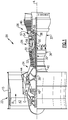
- FIG. 1 schematically illustrates a gas turbine engine 20.
- the gas turbine engine 20 is disclosed herein as a two-spool turbofan that generally incorporates a fan section 22, a compressor section 24, a combustor section 26 and a turbine section 28.
- the fan section 22 drives air along a bypass flow path B in a bypass duct defined within a nacelle 15, while the compressor section 24 drives air along a core flow path C for compression and communication into the combustor section 26 then expansion through the turbine section 28.
- the exemplary engine 20 generally includes a low speed spool 30 and a high speed spool 32 mounted for rotation about an engine central longitudinal axis A relative to an engine static structure 36 via several bearing systems 38. It should be understood that various bearing systems 38 at various locations may alternatively or additionally be provided, and the location of bearing systems 38 may be varied as appropriate to the application.
- the low speed spool 30 generally includes an inner shaft 40 that interconnects a fan 42, a first (or low) pressure compressor 44 and a first (or low) pressure turbine 46.
- the inner shaft 40 is connected to the fan 42 through a speed change mechanism, which in exemplary gas turbine engine 20 is illustrated as a geared architecture 48 to drive the fan 42 at a lower speed than the low speed spool 30.
- the high speed spool 32 includes an outer shaft 50 that interconnects a second (or high) pressure compressor 52 and a second (or high) pressure turbine 54.
- a combustor 56 is arranged in exemplary gas turbine 20 between the high pressure compressor 52 and the high pressure turbine 54.
- a mid-turbine frame 57 of the engine static structure 36 is arranged generally between the high pressure turbine 54 and the low pressure turbine 46.
- the mid-turbine frame 57 further supports bearing systems 38 in the turbine section 28.
- the inner shaft 40 and the outer shaft 50 are concentric and rotate via bearing systems 38 about the engine central longitudinal axis A which is collinear with their longitudinal axes.
- the core airflow is compressed by the low pressure compressor 44 then the high pressure compressor 52, mixed and burned with fuel in the combustor 56, then expanded over the high pressure turbine 54 and low pressure turbine 46.
- the mid-turbine frame 57 includes airfoils 59 which are in the core airflow path C.
- the turbines 46, 54 rotationally drive the respective low speed spool 30 and high speed spool 32 in response to the expansion.
- gear system 48 may be located aft of combustor section 26 or even aft of turbine section 28, and fan section 22 may be positioned forward or aft of the location of gear system 48.
- the engine 20 in one example is a high-bypass geared aircraft engine.
- the engine 20 bypass ratio is greater than about six (6), with an example embodiment being greater than about ten (10)
- the geared architecture 48 is an epicyclic gear train, such as a planetary gear system or other gear system, with a gear reduction ratio of greater than about 2.3
- the low pressure turbine 46 has a pressure ratio that is greater than about five.
- the engine 20 bypass ratio is greater than about ten (10:1)
- the fan diameter is significantly larger than that of the low pressure compressor 44
- the low pressure turbine 46 has a pressure ratio that is greater than about five 5:1.
- Low pressure turbine 46 pressure ratio is pressure measured prior to inlet of low pressure turbine 46 as related to the pressure at the outlet of the low pressure turbine 46 prior to an exhaust nozzle.
- the geared architecture 48 may be an epicycle gear train, such as a planetary gear system or other gear system, with a gear reduction ratio of greater than about 2.3:1. It should be understood, however, that the above parameters are only exemplary of one embodiment of a geared architecture engine and that the present invention is applicable to other gas turbine engines including direct drive turbofans.
- the fan section 22 of the engine 20 is designed for a particular flight condition -- typically cruise at about 0.8 Mach and about 35,000 feet.
- the flight condition of 0.8 Mach and 35,000 ft, with the engine at its best fuel consumption - also known as "bucket cruise Thrust Specific Fuel Consumption ('TSFC')" - is the industry standard parameter of lbm of fuel being burned divided by lbf of thrust the engine produces at that minimum point.
- "Low fan pressure ratio” is the pressure ratio across the fan blade alone, without a Fan Exit Guide Vane (“FEGV”) system.
- the low fan pressure ratio as disclosed herein according to one non-limiting embodiment is less than about 1.45.
- Low corrected fan tip speed is the actual fan tip speed in ft/sec divided by an industry standard temperature correction of [(Tram °R) / (518.7 °R)] ⁇ 0.5 .
- the "Low corrected fan tip speed” as disclosed herein according to one non-limiting embodiment is less than about 1150 ft / second.
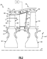
- FIG. 2 shows selected portions of the turbine section 28 including a rotor 60 carrying one or more blades or airfoils 61 that are rotatable about the engine axis A.
- like reference numerals designate like elements where appropriate and reference numerals with the addition of one-hundred or multiples thereof designate modified elements that are understood to incorporate the same features and benefits of the corresponding original elements.
- Each airfoil 61 includes a platform 62 and an airfoil section 65 extending in a radial direction R from the platform 62 to a tip 64.
- the airfoil section 65 generally extends in a chordwise or axial direction X between a leading edge 66 and a trailing edge 68.
- a root section 67 of the airfoil 61 is mounted to, or integrally formed with, the rotor 60.
- a seal assembly 76 includes one or more blade outer air seals (BOAS) 80 that are each spaced radially outward from the tip 64 of the airfoil section 65.
- the BOAS 80 can include a plurality of seal arc segments (one shown in Figure 5 at 180) that are circumferentially arranged in an annulus around the engine axis A to bound the core flow path C.
- a vane 70 is positioned along the engine axis A and adjacent to the airfoil 61.
- the vane 70 includes an airfoil section 71 extending between an inner platform 72 and an outer platform 73 to define a portion of the core flow path C.
- the turbine section 28 includes an array of airfoils 61, vanes 70, and BOAS 80 arranged circumferentially about the engine axis A.
- One or more cooling sources 75 are configured to provide cooling air to one or more cooling cavities or plenums 74 defined by an engine static structure such as the engine case 37 or another portion of the engine static structure 36 ( Figure 1 ).
- the engine case 37 extends along the engine axis A.
- the plenums 74 are defined between an engine case 37 and the outer platform 73 and/or BOAS 80.
- the engine case 37 provides a portion of the engine static structure 36 ( Figure 1 ) and extends along the engine axis A.
- the plenums 74 are configured to receive pressurized cooling flow from the cooling source(s) 75 to cool portions of the airfoil 61, BOAS 80 and/or vane 70.
- Cooling sources 75 can include bleed air from an upstream stage of the compressor section 24 ( Figure 1 ), bypass air, or a secondary cooling system aboard the aircraft, for example.
- Each of the plenums 74 can extend in a circumferential or thickness direction T between adjacent airfoils 61, BOAS 80 and/or vanes 70.
- the tips 64 of each of the airfoil sections 65 and adjacent BOAS 80 are in close radial proximity to reduce the amount of gas flow that escapes around the tips 64 through a corresponding clearance gap.
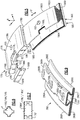
- Figures 3-5 illustrates an exemplary seal assembly 176 for sealing portions a gas turbine engine.
- the seal assembly 176 includes a support 178 and a seal 180.
- the seal assembly 176 can include an array of supports 178 and seals 180 arranged about the engine axis A.
- the seal assembly 176 can be utilized for the seal assembly 76 of Figure 2 or incorporated into a portion of the engine 20 of Figure 1 , for example.
- the seal 180 is a blade outer air seal (BOAS).
- Figure 3 is a sectional view of the seal assembly 176.
- Figure 4 is a perspective view of the seal assembly 176 including the seal 180 in an installed position.
- Figure 5 illustrates an isometric view of the seal assembly 176.
- BOAS blade outer air seal
- the teachings herein can also be utilized for other components of the engine 20, such as one of the platforms 62, 72, 73, an upstream stage of the compressor section 24, or combustor panels or liners defining portions of a combustion chamber located in the combustor section 26.
- the support 178 is mountable to an engine static structure, such as engine case 137 ( Figure 3 ) or another portion of the engine static structure 36 ( Figure 1 ).
- the support 178 includes a main body 178A extends in an axial direction X between leading and trailing edge portions 178B, 178C.
- the main body 178A extends in a circumferential direction T between opposed mate faces 178D, 178E.
- the support 178 includes first and second retention hooks 178F, 178G that extend outwardly from the main body 178A.
- the retention hooks 178F, 178G are omitted from Figures 4 and 5 for illustrative purposes.
- the retention hooks 178F, 178G abut or otherwise engage with portions of the engine case 137 to secure the support 178 to the engine case 137.
- the retention hooks 178F, 178G can be moved in a circumferential direction T along the engine case 137 to mount the support 178 to the engine static structure.
- the support 178 includes a pair of opposed retention hooks 178H for mechanically attaching or otherwise securing the seal 180 to the support 178.
- the retention hooks 178H extend inwardly from the respective leading and trailing edge portions 178B, 178C to bound an elongated circumferential groove 182.
- the retention hooks 178H are integrally formed with the main body 178A of the support. In other examples, the retention hooks 178H are separate and distinct components that are mechanically attached to the main body 178A.
- the groove 182 extends circumferentially between the mate faces 178D, 178E and opens radially inward toward the engine axis A.
- Each of the mate faces 178D, 178E defines a respective opening 184 ( Figures 4 and 5 ) to provide access to the groove 182 for mounting the seal 180.
- An array of the seals 180 is circumferentially distributed about axis A and about an array of blades or airfoils 161 to bound a flow path, such as core flow path C.
- the quantity of supports 178 and quantity of seals 180 in each respective array can be the same or can differ.
- the seal 180 can have a generally elongated and arcuate profile, as illustrated by Figures 4 and 5 .
- the seal 180 includes a main (or seal) body having a sealing portion 180A that extends from an engagement portion 180B.
- the sealing portion 180A can extend radially inward from the engagement portion 180B when in the installed position.
- the sealing portion 180A includes a sealing face 180C that extends in the circumferential direction T between opposed first and second mate faces 180D, 180E.
- the sealing face 180C bounds the core flow path C.
- the sealing face 180C faces radially inward towards the engine axis A and is located in close proximity to a tip 164 of airfoil 161 to define a clearance gap.
- the engagement portion 180B is dimensioned to be secured to the support 178 when in the installed position.
- the engagement portion 180B can extend a full width, or at least half the width, between the mate faces 180D, 180E of the sealing portion 180A, for example.
- the engagement portion 180B can have a dovetail geometry that mates with the retention hooks 178H along an interface 186 ( Figures 3-4 ) to secure the seal 180 to the support 178.
- Each interface 186 is established in the circumferential direction T between the first and second mate faces 180D, 180E.
- the retention hooks 178H can have a complementary geometry with the dovetail geometry along the interface 186 such that the engagement portion 180B can be slideably received along the interface 186 to secure the seal 180, thereby establishing a "bayonetted" circumferential assembly.
- Surfaces of the engagement portion 180B that establish the interface 186 generally face radially outward and away from the engine axis A, with the surfaces along the interface 186 sloping radially inward from the respective leading and trailing edge portions 178B, 178C toward the engine axis A to define a pair of contoured ramps (see Figure 3 ).
- the dovetail geometry and contouring can reduce mechanical stress on the seal 180, including seals made of a ceramic or composite matrix material which can be thermally resilient but relatively brittle.
- the dovetail geometry can define an acute angle, such as between about 30-60 degrees, to reduce mechanical stress.
- the circumferentially extending dovetail geometry also increases a length of engagement along the interface 186 (i.e., larger wheelbase), which can increase circumferential stability of each seal 180 and can reduce intersegment instability or variation in radial positioning between adjacent seals 180 along mate faces 180D, 180E due to thermal loads experienced by the seals 180 during engine operation.
- the dovetail geometry can also reduce deflection along the leading and trailing edges 180F, 180G of each seal 180 due to seal loads and pressure loads during engine operation.
- the engagement portion 180B defines a backside face 180H opposite to, and radially outward of, the sealing face 180C when in the installed position.
- the seal 180 defines a width W between the sealing face 180C and the backside face 180H.
- the sealing portion 180A defines a length L between the leading and trailing edges 180F, 180G.
- the seal 180 can be dimensioned to establish an aspect ratio defined as a ratio of the width W to the length L (W/L). In some examples, the ratio of W/L is less than about 1:1, or more narrowly less than about 2:3. In examples, the ratio of W/L is less than about 1:2 such that a cross-section of the seal 180 is elongated in the axial direction X.
- the exemplary ratios of W/L disclosed herein can establish a relatively smaller radial design space, and can reduce backside areas which influence higher heat transfer and cooling effectiveness, including cavity 298 (see Figures 8-11 ).
- the engine case 137 defines a bore 194, and the support 178 defines a bore 195.
- the bores 194, 195 can be substantially aligned with one another when in the installed position.
- a fastener F can be secured in the bores 194, 195 to mount the support 178 and seal 180 to the engine case 137, as illustrated by Figure 3 .
- the seal assembly 176 can include one or more anti-rotation features to limit movement of the seal 180 in the axial, radial and/or circumferential directions X, R, T.
- the fastener F can provide an anti-rotation feature.
- the engagement portion 180B can define a radially extending bore 193.
- the fastener F is a pin, and each of the bores 193/194/195 can define a spline geometry that mates with a spline geometry of the fastener F.
- the fastener F is a bolt that is threadably received in the bores 194, 195 and protrudes into the bore 193.
- the seal assembly 176 can include anti-rotation features along the leading and/or trailing edge portions 178B, 178C such that the dovetail geometry is interrupted in the circumferential direction T.
- a first retention or locating feature 178L is defined along the leading edge portion 178B.
- the first locating feature 178L cooperates with a second retention or locating feature 180L defined in the engagement portion 180B of the seal 180 to limit relative movement.
- the locating features 178L, 180L define keyways or recesses that are dimensioned to receive a clip or key 196 (shown in dashed lines in Figure 3 ).
- the key 196 includes a main body 196A and a pair of flanges 196B that extend outwardly from the main body 196A.
- the main body 196A has a geometry that complements the locating features 178L, 180L.
- the main body 196A of the key 196 is moved in a direction D2 and is inserted at least partially in the locating features 178L, 180L to oppose relative movement of the support 178 and the seal 180.
- the flanges 196B of the key 196 can be secured to the support 178 utilizing one or more fasteners FF (shown in dashed lines in Figure 3 ).
- main body 196A' defines a spline interface with locating features 178L', 180L', as illustrated by Figure 7 .
- the key 196 and locating features 178L, 180L can reduce rocking of the seal 180 during engine operation.
- the key 196 can be proximally retained by positive assembly of the section of the engine 20, in addition or alternatively to the fasteners FF, including the spline interface or other features of the support 178, abutment with vanes 70 ( Figure 2 ) arranged forward and/or aft of the seal assembly 176 relative to the engine axis A (see, e.g., vane 170' shown in dashed lines in Figure 7 ).
- the support 178 and seal 180 can be exposed to relatively high temperatures due to communication of hot gases along the core flow path C.
- Various materials can be utilized to manufacture the support 178 and seal 180, including a selection of materials to withstand the thermomechanical loads due to the high temperature environment.
- the seal 180 comprises a first material
- the support 178 comprises a second, different material.
- the first material can include a ceramic or ceramic matrix composite (CMC) material, with seal 180 formed of one or more layers of a CMC layup.
- the seal 180 can be made of another material, such as a high temperature metal or alloy.
- the support 178 can be made of a second material such as a high temperature composite, metal, or alloy, such as a nickel-based superalloy.
- the first and second materials can differ.
- the seal 180 is made of a first material
- the support 180 is made of a second material that is the same as the first material, including any of the materials disclosed herein.
- the seal 180 can be formed to have a unitary construction.
- the sealing portion 180A and the engagement portion 180B are separate and distinct components that are mechanically attached to one another.
- the seal 180 is constructed of a CMC material.
- the seal 180 includes an overwrap 188 having one or more layers of overwrap plies OP stacked in layers to define a thickness of the seal 180.
- the overwrap plies OP are oriented to follow a perimeter of the engagement portion 180B between leading and trailing edges 180F, 180G to define the dovetail geometry.
- the overwrap plies OP extend along and establish the interface 186 when the seal 180 is located in the installed position.
- the engagement portion 180B can include a core 190 at least partially surrounded by the overwrap 188.
- the core 190 extends in the circumferential direction T between the mate faces 180D, 180E.
- the overwrap 188 has a first fiber construction defined by the overwrap plies OP.
- the core 190 has second fiber construction, which can be the same or can differ from the first fiber construction.
- the core 190 can be formed from preformed chop fiber strands that extend in different orientations throughout a thickness of the core 190 to define the second fiber construction.
- the overwrap plies OP can be constructed to provide cushioning or absorption of mechanical loads communicated along the interface 186 between the support 178 and the seal 180.
- the core 190 includes a plurality of core plies CP stacked in two-dimensional layers. At least some of the core plies CP can be oriented transversely to the overwrap plies OP. For example, a projection of each the core plies CP in the axial direction X is transverse to an orientation of the overwrap plies OP along the perimeter. A radial projection of the core plies CP can be oriented transversely to a radial projection of the overwrap plies OP along a perimeter of the engagement portion 180B defining the backside face 180H, as illustrated by Figures 3 and 3A .
- Overwrap 188 can include any two dimensional or three dimensional woven construction, including plain or satin two dimensional weaves. An orientation of each of the core plies CP can be the same, or each successive layer can differ from between about 1-15 degrees.
- the seal 180 can include a reinforcement layer 192 that extends radially between the core 190 and sealing portion 180A.
- the reinforcement layer 192 can extend axially between the leading and trailing edges 180F, 180G, and can extend circumferentially between the first and second mate faces 180D, 180E.
- the reinforcement layer 192 can include one or more layers of reinforcement plies RP.
- the sealing portion 180A can comprise a ceramic, which can be applied as a coating to the reinforcement layer 192, for example, to define the sealing face 180C. In other examples, the reinforcement layer 192 defines the sealing face 180C and the coating is omitted.
- the seal assembly 176 can be assembled as follows.
- the engagement portion 180B is moved in a direction D1 and is slideably received through one of the openings 184 and then at least partially into the groove 182 to secure the seal 180 to the support 178 along the interface 186.
- the mate faces 180D, 180E of the seal 180 can be substantially aligned with the respective mate faces 178D, 178E of the support 178 when in the installed position.
- Each set of supports 178 and seals 180 can be mounted to the engine case 137 by moving the supports 178 in the axial direction X to engage retention hooks 178F, 178G with the engine case 137 ( Figure 3 ). Thereafter, the fastener F can be secured in the bores 193, 194, 195 to secure the seal 180 to the engine case 137.
- Dimensioning and assembly of the components of the seal assembly 176 utilizing the teachings disclosed herein can reduce intersegment gap variation along the mate faces 180D, 180E, promote direct circumferential anti-rotation engagement, and reduce axial tipping due to the increased length of engagement along the interfaces 186.
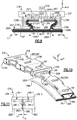
- FIGS 8-11 illustrate a seal assembly 276 according to another example.
- Seal 280 can have a hollow construction to reduce weight and to circulate cooling flow F to cool portions of the seal 280 during engine operation.
- Engagement portion 280B defines an internal cavity 298 that extends circumferentially between mate faces 280D, 280E of the seal 280.
- the seal 280 includes one or more overwrap plies OP including a first (or exterior) set of overwrap plies OP1 that follow a perimeter of the engagement portion 280B and a second (or interior) set of overwrap plies OP2 that follow a perimeter of the internal cavity 298.
- the internal cavity 298 can be free of any core such that cooling flow F from coolant source 275 can be circulated into and through the internal cavity 298 to cool adjacent portions of the seal 280.
- the second set of overwrap plies OP2 can be formed on a mandrel or tool to provide the respective geometry of the internal cavity 298.
- the seal 280 includes reinforcement layer 292 having a set of reinforcement plies RP that extend along the first and second sets of plies OP1, OP2 to define sealing portion 280A.
- a fiber filler such as chopped fiber preform, can be placed in regions RF ( Figure 8 ) between the plies OP1, OP2 and/or RP to reduce voids in a volume of the seal 280.
- the engagement portion 280B defines one or more cooling passages 299 in fluid communication with the internal cavity 298.
- Main body 278A of support 278 defines one or more apertures 297 that interconnect the cooling passages 299 with the coolant source 275.
- the apertures 297 communicate cooling flow F between the coolant source 275 and the internal cavity 298.
- Each engagement portion 280B can define one or more openings 291 along each of the respective mate faces 280D, 280E to provide access to the internal cavity 298.
- the backside face 280H of the seal 280 can be spaced apart from the support 278 to establish a plenum 274, as illustrated by Figure 8 , or can be brought into abutment when in the installed position.
- the support 278 can define one or more apertures 297' (shown in dashed lines in Figure 8 ) offset from the cooling passages 299.
- the apertures 297' can be oriented to eject cooling flow F in a direction towards surfaces of the backside face 280H of the seal 280 to provide impingement cooling for adjacent portions of the seal 280.
- a length of the sealing portion 280A can be dimensioned according to expected pressure loads during engine operation.
- the sealing portion 280A defines a first length L1 between leading edge 280F and the dovetail geometry defined by the engagement portion 280B.
- the sealing portion 280A defines a second length L2 between trailing edge 280G and the dovetail geometry.
- the first length L1 can differ from the second length L2.
- the first length L1 is greater than the second length L2 to accommodate relatively greater pressure loads along the second length L2 of the sealing portion 280A.
- pressurized cooling flow F is communicated from the coolant source 275 to the cooling passages 299 and then into the internal cavity 298.
- a pair of adjacent seals 280 is illustrated as seals 280-1, 280-2.
- Cooling flow F is communicated from the internal cavity 298 and through the through the respective openings 291, and into an intersegment gap G defined by mate faces 280D, 280E of the seals 280-1, 280-2.
- the cooling flow F can be ejected from the intersegment gap G into the gas path radially inward of the sealing faces 280C.
- the cooling arrangement of seal assembly 276 can reduce thermal gradients across the portions of the seals 280 during engine operation and can improve durability, for example.
Landscapes
- Engineering & Computer Science (AREA)
- Mechanical Engineering (AREA)
- General Engineering & Computer Science (AREA)
- Chemical & Material Sciences (AREA)
- Materials Engineering (AREA)
- Turbine Rotor Nozzle Sealing (AREA)
Applications Claiming Priority (1)
| Application Number | Priority Date | Filing Date | Title |
|---|---|---|---|
| US15/995,328 US11035243B2 (en) | 2018-06-01 | 2018-06-01 | Seal assembly for gas turbine engines |
Publications (2)
| Publication Number | Publication Date |
|---|---|
| EP3575558A1 true EP3575558A1 (fr) | 2019-12-04 |
| EP3575558B1 EP3575558B1 (fr) | 2021-03-31 |
Family
ID=66677049
Family Applications (1)
| Application Number | Title | Priority Date | Filing Date |
|---|---|---|---|
| EP19177484.3A Active EP3575558B1 (fr) | 2018-06-01 | 2019-05-30 | Ensemble d'étanchéité pour moteurs à turbine à gaz et méthode d'étancheité correspondante |
Country Status (2)
| Country | Link |
|---|---|
| US (1) | US11035243B2 (fr) |
| EP (1) | EP3575558B1 (fr) |
Cited By (5)
| Publication number | Priority date | Publication date | Assignee | Title |
|---|---|---|---|---|
| EP3712383A1 (fr) * | 2019-03-18 | 2020-09-23 | United Technologies Corporation | Joint d'air extérieur d'aube cmc |
| EP3719264A1 (fr) * | 2019-04-05 | 2020-10-07 | United Technologies Corporation | Joint d'étanchéité à l'air externe d'aube en cmc avec agencement de crochet transversal |
| EP3798420A1 (fr) * | 2019-09-26 | 2021-03-31 | Raytheon Technologies Corporation | Ensemble joint composite à double boîtier pour moteur à turbine à gaz |
| EP3798422A1 (fr) * | 2019-09-26 | 2021-03-31 | Raytheon Technologies Corporation | Ensemble joint composite à double boîtier doté d'un insert pour moteur à turbine à gaz |
| EP3798421A1 (fr) * | 2019-09-26 | 2021-03-31 | Raytheon Technologies Corporation | Ensemble joint composite à double boîte avec agencement de densité de fibres pour moteur à turbine à gaz |
Families Citing this family (5)
| Publication number | Priority date | Publication date | Assignee | Title |
|---|---|---|---|---|
| US11242764B2 (en) * | 2018-05-17 | 2022-02-08 | Raytheon Technologies Corporation | Seal assembly with baffle for gas turbine engine |
| US10634010B2 (en) * | 2018-09-05 | 2020-04-28 | United Technologies Corporation | CMC BOAS axial retaining clip |
| US10934877B2 (en) | 2018-10-31 | 2021-03-02 | Raytheon Technologies Corporation | CMC laminate pocket BOAS with axial attachment scheme |
| US11008894B2 (en) * | 2018-10-31 | 2021-05-18 | Raytheon Technologies Corporation | BOAS spring clip |
| US11365644B2 (en) * | 2019-07-01 | 2022-06-21 | Raytheon Technologies Corporation | Double box boas and carrier system |
Citations (9)
| Publication number | Priority date | Publication date | Assignee | Title |
|---|---|---|---|---|
| JP2007071185A (ja) * | 2005-09-09 | 2007-03-22 | Chugoku Electric Power Co Inc:The | ガスタービン用のシュラウド |
| EP2784272A2 (fr) * | 2013-03-28 | 2014-10-01 | Rolls-Royce plc | Segment d'étanchéité d'une turbine à gaz à materiau composite de matrice céramique |
| WO2015023576A1 (fr) * | 2013-08-15 | 2015-02-19 | United Technologies Corporation | Panneau de protection et cadre à cet effet |
| WO2015109292A1 (fr) * | 2014-01-20 | 2015-07-23 | United Technologies Corporation | Attache de retenue pour un joint de pale étanche à l'air extérieur |
| US20160102572A1 (en) * | 2014-10-14 | 2016-04-14 | Rolls-Royce Corporation | Turbine shroud with biased blade track |
| EP3115559A1 (fr) * | 2015-06-29 | 2017-01-11 | Rolls-Royce Corporation | Viroles de turbine avec système de distribution d'air de refroidissement intégré |
| EP3156606A2 (fr) * | 2015-10-14 | 2017-04-19 | General Electric Company | Anneau de cerclage et procédés de formation de composants de turbine |
| EP3255252A1 (fr) * | 2016-06-07 | 2017-12-13 | United Technologies Corporation | Joint d'air extérieur d'aube constitué d'un composite à matrice céramique |
| EP3444440A1 (fr) * | 2017-05-23 | 2019-02-20 | Rolls-Royce Corporation | Ensemble d'enveloppe de turbine comprenant des segments de piste composites à matrice céramique ayant des caractéristiques de fixation métallique |
Family Cites Families (8)
| Publication number | Priority date | Publication date | Assignee | Title |
|---|---|---|---|---|
| US4087199A (en) * | 1976-11-22 | 1978-05-02 | General Electric Company | Ceramic turbine shroud assembly |
| US6733235B2 (en) | 2002-03-28 | 2004-05-11 | General Electric Company | Shroud segment and assembly for a turbine engine |
| US9039358B2 (en) | 2007-01-03 | 2015-05-26 | United Technologies Corporation | Replaceable blade outer air seal design |
| US8740552B2 (en) | 2010-05-28 | 2014-06-03 | General Electric Company | Low-ductility turbine shroud and mounting apparatus |
| JP5569194B2 (ja) * | 2010-07-02 | 2014-08-13 | 株式会社Ihi | シュラウドセグメントの製造方法 |
| EP2971587B1 (fr) * | 2013-03-12 | 2020-02-05 | Rolls-Royce Corporation | Ensemble de sillages de pales de turbine |
| US10309257B2 (en) | 2015-03-02 | 2019-06-04 | Rolls-Royce North American Technologies Inc. | Turbine assembly with load pads |
| FR3036435B1 (fr) * | 2015-05-22 | 2020-01-24 | Safran Ceramics | Ensemble d'anneau de turbine |
-
2018
- 2018-06-01 US US15/995,328 patent/US11035243B2/en active Active
-
2019
- 2019-05-30 EP EP19177484.3A patent/EP3575558B1/fr active Active
Patent Citations (9)
| Publication number | Priority date | Publication date | Assignee | Title |
|---|---|---|---|---|
| JP2007071185A (ja) * | 2005-09-09 | 2007-03-22 | Chugoku Electric Power Co Inc:The | ガスタービン用のシュラウド |
| EP2784272A2 (fr) * | 2013-03-28 | 2014-10-01 | Rolls-Royce plc | Segment d'étanchéité d'une turbine à gaz à materiau composite de matrice céramique |
| WO2015023576A1 (fr) * | 2013-08-15 | 2015-02-19 | United Technologies Corporation | Panneau de protection et cadre à cet effet |
| WO2015109292A1 (fr) * | 2014-01-20 | 2015-07-23 | United Technologies Corporation | Attache de retenue pour un joint de pale étanche à l'air extérieur |
| US20160102572A1 (en) * | 2014-10-14 | 2016-04-14 | Rolls-Royce Corporation | Turbine shroud with biased blade track |
| EP3115559A1 (fr) * | 2015-06-29 | 2017-01-11 | Rolls-Royce Corporation | Viroles de turbine avec système de distribution d'air de refroidissement intégré |
| EP3156606A2 (fr) * | 2015-10-14 | 2017-04-19 | General Electric Company | Anneau de cerclage et procédés de formation de composants de turbine |
| EP3255252A1 (fr) * | 2016-06-07 | 2017-12-13 | United Technologies Corporation | Joint d'air extérieur d'aube constitué d'un composite à matrice céramique |
| EP3444440A1 (fr) * | 2017-05-23 | 2019-02-20 | Rolls-Royce Corporation | Ensemble d'enveloppe de turbine comprenant des segments de piste composites à matrice céramique ayant des caractéristiques de fixation métallique |
Cited By (9)
| Publication number | Priority date | Publication date | Assignee | Title |
|---|---|---|---|---|
| EP3712383A1 (fr) * | 2019-03-18 | 2020-09-23 | United Technologies Corporation | Joint d'air extérieur d'aube cmc |
| EP3719264A1 (fr) * | 2019-04-05 | 2020-10-07 | United Technologies Corporation | Joint d'étanchéité à l'air externe d'aube en cmc avec agencement de crochet transversal |
| US11047250B2 (en) | 2019-04-05 | 2021-06-29 | Raytheon Technologies Corporation | CMC BOAS transverse hook arrangement |
| EP3798420A1 (fr) * | 2019-09-26 | 2021-03-31 | Raytheon Technologies Corporation | Ensemble joint composite à double boîtier pour moteur à turbine à gaz |
| EP3798422A1 (fr) * | 2019-09-26 | 2021-03-31 | Raytheon Technologies Corporation | Ensemble joint composite à double boîtier doté d'un insert pour moteur à turbine à gaz |
| EP3798421A1 (fr) * | 2019-09-26 | 2021-03-31 | Raytheon Technologies Corporation | Ensemble joint composite à double boîte avec agencement de densité de fibres pour moteur à turbine à gaz |
| EP4219908A1 (fr) * | 2019-09-26 | 2023-08-02 | Raytheon Technologies Corporation | Ensemble joint d'étanchéité composite à double boîte avec agencement de densité de fibres pour moteur à turbine à gaz |
| EP4219909A1 (fr) * | 2019-09-26 | 2023-08-02 | Raytheon Technologies Corporation | Ensemble joint d'étanchéité composite à double boîte avec insert pour moteur à turbine à gaz |
| US11732597B2 (en) | 2019-09-26 | 2023-08-22 | Raytheon Technologies Corporation | Double box composite seal assembly with insert for gas turbine engine |
Also Published As
| Publication number | Publication date |
|---|---|
| US11035243B2 (en) | 2021-06-15 |
| EP3575558B1 (fr) | 2021-03-31 |
| US20190368366A1 (en) | 2019-12-05 |
Similar Documents
| Publication | Publication Date | Title |
|---|---|---|
| EP3575558B1 (fr) | Ensemble d'étanchéité pour moteurs à turbine à gaz et méthode d'étancheité correspondante | |
| US11466585B2 (en) | Blade outer air seal arrangement and method of sealing | |
| US10968761B2 (en) | Seal assembly with impingement seal plate | |
| EP3170981B1 (fr) | Une aube comprennant une chicane, un moteur de turbine à gaz, et procédé de réparation d'une aube | |
| EP3792453B1 (fr) | Ensemble boas cmc | |
| US11021986B2 (en) | Seal assembly for gas turbine engine | |
| US10801351B2 (en) | Seal assembly for gas turbine engine | |
| EP4001592A1 (fr) | Segment d'arc de cercle cmc avec longeron en porte-à-faux | |
| EP3892822B1 (fr) | Système de support d'aube statorique | |
| EP3767075A1 (fr) | Ensemble avec joint d'air extérieur d'aube en composite à matrice céramique | |
| EP3557003B1 (fr) | Ensemble d'étanchéité pour moteur à turbine à gaz | |
| EP3569823B1 (fr) | Ensemble d'étanchéité doté d'un déflecteur pour moteur à turbine à gaz | |
| EP4015771B1 (fr) | Segment d'arc d'aube avec élément d'isolation thermique | |
| EP3825518B1 (fr) | Agencement de rétention d'aube directrice | |
| EP3708784B1 (fr) | Ensemble de joint d'air externe d'aubes (boas) avec alimentation de refroidissement | |
| EP3620611B1 (fr) | Support de joint d'air externe de lame unifié et plateforme de pale | |
| EP3767077B1 (fr) | Agencement boas cmc | |
| US11220917B1 (en) | Diffused cooling arrangement for gas turbine engine components | |
| EP4276278A1 (fr) | Article de moteur à turbine à gaz avec bride ramifiée | |
| EP3808940B1 (fr) | Surface portante en cmc pour un moteur à turbine à gaz comportant des trous de refroidissement | |
| US11125099B2 (en) | Boas arrangement with double dovetail attachments | |
| EP3767076A1 (fr) | Ensemble avec joint d'air extérieur d'aube en composite à matrice céramique | |
| EP4317653A1 (fr) | Multi-aubes avec plate-forme commune reliant des aubes | |
| EP4086434A2 (fr) | Aube en cmc avec couvercle de plateforme | |
| EP3767078A1 (fr) | Agencement boas cmc |
Legal Events
| Date | Code | Title | Description |
|---|---|---|---|
| PUAI | Public reference made under article 153(3) epc to a published international application that has entered the european phase |
Free format text: ORIGINAL CODE: 0009012 |
|
| STAA | Information on the status of an ep patent application or granted ep patent |
Free format text: STATUS: THE APPLICATION HAS BEEN PUBLISHED |
|
| AK | Designated contracting states |
Kind code of ref document: A1 Designated state(s): AL AT BE BG CH CY CZ DE DK EE ES FI FR GB GR HR HU IE IS IT LI LT LU LV MC MK MT NL NO PL PT RO RS SE SI SK SM TR |
|
| AX | Request for extension of the european patent |
Extension state: BA ME |
|
| STAA | Information on the status of an ep patent application or granted ep patent |
Free format text: STATUS: REQUEST FOR EXAMINATION WAS MADE |
|
| 17P | Request for examination filed |
Effective date: 20200603 |
|
| RBV | Designated contracting states (corrected) |
Designated state(s): AL AT BE BG CH CY CZ DE DK EE ES FI FR GB GR HR HU IE IS IT LI LT LU LV MC MK MT NL NO PL PT RO RS SE SI SK SM TR |
|
| GRAP | Despatch of communication of intention to grant a patent |
Free format text: ORIGINAL CODE: EPIDOSNIGR1 |
|
| STAA | Information on the status of an ep patent application or granted ep patent |
Free format text: STATUS: GRANT OF PATENT IS INTENDED |
|
| INTG | Intention to grant announced |
Effective date: 20201109 |
|
| GRAS | Grant fee paid |
Free format text: ORIGINAL CODE: EPIDOSNIGR3 |
|
| GRAA | (expected) grant |
Free format text: ORIGINAL CODE: 0009210 |
|
| STAA | Information on the status of an ep patent application or granted ep patent |
Free format text: STATUS: THE PATENT HAS BEEN GRANTED |
|
| RAP1 | Party data changed (applicant data changed or rights of an application transferred) |
Owner name: RAYTHEON TECHNOLOGIES CORPORATION |
|
| AK | Designated contracting states |
Kind code of ref document: B1 Designated state(s): AL AT BE BG CH CY CZ DE DK EE ES FI FR GB GR HR HU IE IS IT LI LT LU LV MC MK MT NL NO PL PT RO RS SE SI SK SM TR |
|
| REG | Reference to a national code |
Ref country code: GB Ref legal event code: FG4D Ref country code: CH Ref legal event code: EP |
|
| REG | Reference to a national code |
Ref country code: DE Ref legal event code: R096 Ref document number: 602019003546 Country of ref document: DE Ref country code: AT Ref legal event code: REF Ref document number: 1377146 Country of ref document: AT Kind code of ref document: T Effective date: 20210415 |
|
| REG | Reference to a national code |
Ref country code: IE Ref legal event code: FG4D |
|
| REG | Reference to a national code |
Ref country code: LT Ref legal event code: MG9D |
|
| PG25 | Lapsed in a contracting state [announced via postgrant information from national office to epo] |
Ref country code: NO Free format text: LAPSE BECAUSE OF FAILURE TO SUBMIT A TRANSLATION OF THE DESCRIPTION OR TO PAY THE FEE WITHIN THE PRESCRIBED TIME-LIMIT Effective date: 20210630 Ref country code: HR Free format text: LAPSE BECAUSE OF FAILURE TO SUBMIT A TRANSLATION OF THE DESCRIPTION OR TO PAY THE FEE WITHIN THE PRESCRIBED TIME-LIMIT Effective date: 20210331 Ref country code: BG Free format text: LAPSE BECAUSE OF FAILURE TO SUBMIT A TRANSLATION OF THE DESCRIPTION OR TO PAY THE FEE WITHIN THE PRESCRIBED TIME-LIMIT Effective date: 20210630 Ref country code: FI Free format text: LAPSE BECAUSE OF FAILURE TO SUBMIT A TRANSLATION OF THE DESCRIPTION OR TO PAY THE FEE WITHIN THE PRESCRIBED TIME-LIMIT Effective date: 20210331 |
|
| PG25 | Lapsed in a contracting state [announced via postgrant information from national office to epo] |
Ref country code: RS Free format text: LAPSE BECAUSE OF FAILURE TO SUBMIT A TRANSLATION OF THE DESCRIPTION OR TO PAY THE FEE WITHIN THE PRESCRIBED TIME-LIMIT Effective date: 20210331 Ref country code: SE Free format text: LAPSE BECAUSE OF FAILURE TO SUBMIT A TRANSLATION OF THE DESCRIPTION OR TO PAY THE FEE WITHIN THE PRESCRIBED TIME-LIMIT Effective date: 20210331 Ref country code: LV Free format text: LAPSE BECAUSE OF FAILURE TO SUBMIT A TRANSLATION OF THE DESCRIPTION OR TO PAY THE FEE WITHIN THE PRESCRIBED TIME-LIMIT Effective date: 20210331 |
|
| REG | Reference to a national code |
Ref country code: NL Ref legal event code: MP Effective date: 20210331 |
|
| REG | Reference to a national code |
Ref country code: AT Ref legal event code: MK05 Ref document number: 1377146 Country of ref document: AT Kind code of ref document: T Effective date: 20210331 |
|
| PG25 | Lapsed in a contracting state [announced via postgrant information from national office to epo] |
Ref country code: LT Free format text: LAPSE BECAUSE OF FAILURE TO SUBMIT A TRANSLATION OF THE DESCRIPTION OR TO PAY THE FEE WITHIN THE PRESCRIBED TIME-LIMIT Effective date: 20210331 Ref country code: EE Free format text: LAPSE BECAUSE OF FAILURE TO SUBMIT A TRANSLATION OF THE DESCRIPTION OR TO PAY THE FEE WITHIN THE PRESCRIBED TIME-LIMIT Effective date: 20210331 Ref country code: CZ Free format text: LAPSE BECAUSE OF FAILURE TO SUBMIT A TRANSLATION OF THE DESCRIPTION OR TO PAY THE FEE WITHIN THE PRESCRIBED TIME-LIMIT Effective date: 20210331 Ref country code: NL Free format text: LAPSE BECAUSE OF FAILURE TO SUBMIT A TRANSLATION OF THE DESCRIPTION OR TO PAY THE FEE WITHIN THE PRESCRIBED TIME-LIMIT Effective date: 20210331 Ref country code: SM Free format text: LAPSE BECAUSE OF FAILURE TO SUBMIT A TRANSLATION OF THE DESCRIPTION OR TO PAY THE FEE WITHIN THE PRESCRIBED TIME-LIMIT Effective date: 20210331 Ref country code: AT Free format text: LAPSE BECAUSE OF FAILURE TO SUBMIT A TRANSLATION OF THE DESCRIPTION OR TO PAY THE FEE WITHIN THE PRESCRIBED TIME-LIMIT Effective date: 20210331 |
|
| PG25 | Lapsed in a contracting state [announced via postgrant information from national office to epo] |
Ref country code: SK Free format text: LAPSE BECAUSE OF FAILURE TO SUBMIT A TRANSLATION OF THE DESCRIPTION OR TO PAY THE FEE WITHIN THE PRESCRIBED TIME-LIMIT Effective date: 20210331 Ref country code: RO Free format text: LAPSE BECAUSE OF FAILURE TO SUBMIT A TRANSLATION OF THE DESCRIPTION OR TO PAY THE FEE WITHIN THE PRESCRIBED TIME-LIMIT Effective date: 20210331 Ref country code: PT Free format text: LAPSE BECAUSE OF FAILURE TO SUBMIT A TRANSLATION OF THE DESCRIPTION OR TO PAY THE FEE WITHIN THE PRESCRIBED TIME-LIMIT Effective date: 20210802 Ref country code: PL Free format text: LAPSE BECAUSE OF FAILURE TO SUBMIT A TRANSLATION OF THE DESCRIPTION OR TO PAY THE FEE WITHIN THE PRESCRIBED TIME-LIMIT Effective date: 20210331 Ref country code: IS Free format text: LAPSE BECAUSE OF FAILURE TO SUBMIT A TRANSLATION OF THE DESCRIPTION OR TO PAY THE FEE WITHIN THE PRESCRIBED TIME-LIMIT Effective date: 20210731 |
|
| REG | Reference to a national code |
Ref country code: DE Ref legal event code: R097 Ref document number: 602019003546 Country of ref document: DE |
|
| PG25 | Lapsed in a contracting state [announced via postgrant information from national office to epo] |
Ref country code: ES Free format text: LAPSE BECAUSE OF FAILURE TO SUBMIT A TRANSLATION OF THE DESCRIPTION OR TO PAY THE FEE WITHIN THE PRESCRIBED TIME-LIMIT Effective date: 20210331 Ref country code: LU Free format text: LAPSE BECAUSE OF NON-PAYMENT OF DUE FEES Effective date: 20210530 Ref country code: AL Free format text: LAPSE BECAUSE OF FAILURE TO SUBMIT A TRANSLATION OF THE DESCRIPTION OR TO PAY THE FEE WITHIN THE PRESCRIBED TIME-LIMIT Effective date: 20210331 Ref country code: DK Free format text: LAPSE BECAUSE OF FAILURE TO SUBMIT A TRANSLATION OF THE DESCRIPTION OR TO PAY THE FEE WITHIN THE PRESCRIBED TIME-LIMIT Effective date: 20210331 Ref country code: MC Free format text: LAPSE BECAUSE OF FAILURE TO SUBMIT A TRANSLATION OF THE DESCRIPTION OR TO PAY THE FEE WITHIN THE PRESCRIBED TIME-LIMIT Effective date: 20210331 |
|
| PLBE | No opposition filed within time limit |
Free format text: ORIGINAL CODE: 0009261 |
|
| STAA | Information on the status of an ep patent application or granted ep patent |
Free format text: STATUS: NO OPPOSITION FILED WITHIN TIME LIMIT |
|
| REG | Reference to a national code |
Ref country code: BE Ref legal event code: MM Effective date: 20210531 |
|
| 26N | No opposition filed |
Effective date: 20220104 |
|
| PG25 | Lapsed in a contracting state [announced via postgrant information from national office to epo] |
Ref country code: IE Free format text: LAPSE BECAUSE OF NON-PAYMENT OF DUE FEES Effective date: 20210530 |
|
| PG25 | Lapsed in a contracting state [announced via postgrant information from national office to epo] |
Ref country code: IS Free format text: LAPSE BECAUSE OF FAILURE TO SUBMIT A TRANSLATION OF THE DESCRIPTION OR TO PAY THE FEE WITHIN THE PRESCRIBED TIME-LIMIT Effective date: 20210731 |
|
| PG25 | Lapsed in a contracting state [announced via postgrant information from national office to epo] |
Ref country code: IT Free format text: LAPSE BECAUSE OF FAILURE TO SUBMIT A TRANSLATION OF THE DESCRIPTION OR TO PAY THE FEE WITHIN THE PRESCRIBED TIME-LIMIT Effective date: 20210331 Ref country code: BE Free format text: LAPSE BECAUSE OF NON-PAYMENT OF DUE FEES Effective date: 20210531 |
|
| REG | Reference to a national code |
Ref country code: CH Ref legal event code: PL |
|
| PG25 | Lapsed in a contracting state [announced via postgrant information from national office to epo] |
Ref country code: LI Free format text: LAPSE BECAUSE OF NON-PAYMENT OF DUE FEES Effective date: 20220531 Ref country code: CH Free format text: LAPSE BECAUSE OF NON-PAYMENT OF DUE FEES Effective date: 20220531 |
|
| P01 | Opt-out of the competence of the unified patent court (upc) registered |
Effective date: 20230521 |
|
| PG25 | Lapsed in a contracting state [announced via postgrant information from national office to epo] |
Ref country code: CY Free format text: LAPSE BECAUSE OF FAILURE TO SUBMIT A TRANSLATION OF THE DESCRIPTION OR TO PAY THE FEE WITHIN THE PRESCRIBED TIME-LIMIT Effective date: 20210331 |
|
| PG25 | Lapsed in a contracting state [announced via postgrant information from national office to epo] |
Ref country code: HU Free format text: LAPSE BECAUSE OF FAILURE TO SUBMIT A TRANSLATION OF THE DESCRIPTION OR TO PAY THE FEE WITHIN THE PRESCRIBED TIME-LIMIT; INVALID AB INITIO Effective date: 20190530 Ref country code: GR Free format text: LAPSE BECAUSE OF FAILURE TO SUBMIT A TRANSLATION OF THE DESCRIPTION OR TO PAY THE FEE WITHIN THE PRESCRIBED TIME-LIMIT Effective date: 20210331 |
|
| PGFP | Annual fee paid to national office [announced via postgrant information from national office to epo] |
Ref country code: FR Payment date: 20230420 Year of fee payment: 5 Ref country code: DE Payment date: 20230419 Year of fee payment: 5 |
|
| PGFP | Annual fee paid to national office [announced via postgrant information from national office to epo] |
Ref country code: GB Payment date: 20230420 Year of fee payment: 5 |
|
| PG25 | Lapsed in a contracting state [announced via postgrant information from national office to epo] |
Ref country code: MK Free format text: LAPSE BECAUSE OF FAILURE TO SUBMIT A TRANSLATION OF THE DESCRIPTION OR TO PAY THE FEE WITHIN THE PRESCRIBED TIME-LIMIT Effective date: 20210331 |