EP2784272A2 - Segment d'étanchéité d'une turbine à gaz à materiau composite de matrice céramique - Google Patents
Segment d'étanchéité d'une turbine à gaz à materiau composite de matrice céramique Download PDFInfo
- Publication number
- EP2784272A2 EP2784272A2 EP14161521.1A EP14161521A EP2784272A2 EP 2784272 A2 EP2784272 A2 EP 2784272A2 EP 14161521 A EP14161521 A EP 14161521A EP 2784272 A2 EP2784272 A2 EP 2784272A2
- Authority
- EP
- European Patent Office
- Prior art keywords
- body portion
- seal segment
- sub
- component
- slot
- Prior art date
- Legal status (The legal status is an assumption and is not a legal conclusion. Google has not performed a legal analysis and makes no representation as to the accuracy of the status listed.)
- Granted
Links
Images


Classifications
-
- F—MECHANICAL ENGINEERING; LIGHTING; HEATING; WEAPONS; BLASTING
- F01—MACHINES OR ENGINES IN GENERAL; ENGINE PLANTS IN GENERAL; STEAM ENGINES
- F01D—NON-POSITIVE DISPLACEMENT MACHINES OR ENGINES, e.g. STEAM TURBINES
- F01D5/00—Blades; Blade-carrying members; Heating, heat-insulating, cooling or antivibration means on the blades or the members
- F01D5/12—Blades
- F01D5/28—Selecting particular materials; Particular measures relating thereto; Measures against erosion or corrosion
-
- F—MECHANICAL ENGINEERING; LIGHTING; HEATING; WEAPONS; BLASTING
- F01—MACHINES OR ENGINES IN GENERAL; ENGINE PLANTS IN GENERAL; STEAM ENGINES
- F01D—NON-POSITIVE DISPLACEMENT MACHINES OR ENGINES, e.g. STEAM TURBINES
- F01D11/00—Preventing or minimising internal leakage of working-fluid, e.g. between stages
- F01D11/08—Preventing or minimising internal leakage of working-fluid, e.g. between stages for sealing space between rotor blade tips and stator
- F01D11/12—Preventing or minimising internal leakage of working-fluid, e.g. between stages for sealing space between rotor blade tips and stator using a rubstrip, e.g. erodible. deformable or resiliently-biased part
- F01D11/122—Preventing or minimising internal leakage of working-fluid, e.g. between stages for sealing space between rotor blade tips and stator using a rubstrip, e.g. erodible. deformable or resiliently-biased part with erodable or abradable material
-
- F—MECHANICAL ENGINEERING; LIGHTING; HEATING; WEAPONS; BLASTING
- F01—MACHINES OR ENGINES IN GENERAL; ENGINE PLANTS IN GENERAL; STEAM ENGINES
- F01D—NON-POSITIVE DISPLACEMENT MACHINES OR ENGINES, e.g. STEAM TURBINES
- F01D11/00—Preventing or minimising internal leakage of working-fluid, e.g. between stages
- F01D11/08—Preventing or minimising internal leakage of working-fluid, e.g. between stages for sealing space between rotor blade tips and stator
-
- F—MECHANICAL ENGINEERING; LIGHTING; HEATING; WEAPONS; BLASTING
- F01—MACHINES OR ENGINES IN GENERAL; ENGINE PLANTS IN GENERAL; STEAM ENGINES
- F01D—NON-POSITIVE DISPLACEMENT MACHINES OR ENGINES, e.g. STEAM TURBINES
- F01D25/00—Component parts, details, or accessories, not provided for in, or of interest apart from, other groups
- F01D25/005—Selecting particular materials
-
- F—MECHANICAL ENGINEERING; LIGHTING; HEATING; WEAPONS; BLASTING
- F01—MACHINES OR ENGINES IN GENERAL; ENGINE PLANTS IN GENERAL; STEAM ENGINES
- F01D—NON-POSITIVE DISPLACEMENT MACHINES OR ENGINES, e.g. STEAM TURBINES
- F01D5/00—Blades; Blade-carrying members; Heating, heat-insulating, cooling or antivibration means on the blades or the members
- F01D5/12—Blades
- F01D5/28—Selecting particular materials; Particular measures relating thereto; Measures against erosion or corrosion
- F01D5/284—Selection of ceramic materials
-
- F—MECHANICAL ENGINEERING; LIGHTING; HEATING; WEAPONS; BLASTING
- F01—MACHINES OR ENGINES IN GENERAL; ENGINE PLANTS IN GENERAL; STEAM ENGINES
- F01D—NON-POSITIVE DISPLACEMENT MACHINES OR ENGINES, e.g. STEAM TURBINES
- F01D9/00—Stators
- F01D9/02—Nozzles; Nozzle boxes; Stator blades; Guide conduits, e.g. individual nozzles
- F01D9/04—Nozzles; Nozzle boxes; Stator blades; Guide conduits, e.g. individual nozzles forming ring or sector
-
- Y—GENERAL TAGGING OF NEW TECHNOLOGICAL DEVELOPMENTS; GENERAL TAGGING OF CROSS-SECTIONAL TECHNOLOGIES SPANNING OVER SEVERAL SECTIONS OF THE IPC; TECHNICAL SUBJECTS COVERED BY FORMER USPC CROSS-REFERENCE ART COLLECTIONS [XRACs] AND DIGESTS
- Y02—TECHNOLOGIES OR APPLICATIONS FOR MITIGATION OR ADAPTATION AGAINST CLIMATE CHANGE
- Y02T—CLIMATE CHANGE MITIGATION TECHNOLOGIES RELATED TO TRANSPORTATION
- Y02T50/00—Aeronautics or air transport
- Y02T50/60—Efficient propulsion technologies, e.g. for aircraft
Definitions
- the present invention relates to a seal segment for a shroud ring of a rotor of a gas turbine engine, the segment including a body portion formed from continuous fibre reinforced ceramic matrix composite.
- EP 0751104 discloses a ceramic segment having an abradable seal which is suitable for use with nickel base turbine blades
- EP 1965030 discloses a hollow section ceramic seal segment.
- a conventional method of attaching shroud segments to other components is a "birdmouth" type assembly, in which a slot in one component is attached to a hook in another component. When assembled, the two components can then locate across an interface which is perpendicular to the direction of the primary load.
- the present invention provides a seal segment for a shroud ring of a rotor of a gas turbine engine, the seal segment being positioned, in use, radially adjacent the rotor, wherein:
- the present invention provides a shroud ring of a rotor of a gas turbine engine, the shroud ring including an annular array of seal segments of the first aspect.
- the present invention provides a gas turbine engine having the shroud ring of the second aspect.
- the body portion bonded-together sub-components may be bonded using ceramic cement for example.
- a body portion built up from a plurality of sub-components can be easier to manufacture from continuous fibre reinforced ceramic matrix composite than a body portion which is put together as one piece.
- reinforcing fibres of the composite may lie substantially parallel to a radially inward facing surface of the body portion. These fibres can then be appropriately arranged to withstand bending stresses in the body portion (the bending stresses primarily being produced by pressure and temperature differentials across the radial thickness of the seal segment, and reaction loads at the slots), and also to resist crack growth in a radial direction through segment.
- the reinforcing fibres can lie in plys that are dished towards the radially inward facing surface of the body portion. Such dishing can improve the loading performance of the fibres.
- a central sub-component of the body portion may form the central section of the body portion, the central sub-component being bonded at front and rear sides thereof to the C-section sub-components which form the body portion in the vicinity of the slots.
- a separate inner sub-component of the body portion may then form the radially inward facing surface of the body portion, the reinforcing fibres in the inner sub-component being parallel to the radially inward facing surface, and the inner sub-component being bonded at a radially outer surface thereof to the central sub-component.
- the central and C-section sub-components can be bonded together at an interface surface.
- a portion of the interface surface may be radially inclined to the radially inward facing surface.
- the radial inclination may tangential to a radius of a dished ply.
- the radially inclined interface surface may be straight or curved.
- the curvature may have the same curvature as the dished ply.
- the seal segment can include an abradable ceramic coating on the radially inward facing surface of the body portion.
- the coating may comprise hollow ceramic spheres in a ceramic matrix, e.g. as disclosed in EP 0751104 .
- the seal segment may have circumferentially opposing side faces, each side face providing a respective further slot which extends in the fore and aft direction and which, in the shroud ring, contains a respective strip seal for sealing the seal segment to a circumferentially adjacent seal segment.
- a ducted fan gas turbine engine generally indicated at 10 has a principal and rotational axis X-X.
- the engine comprises, in axial flow series, an air intake 11, a propulsive fan 12, an intermediate pressure compressor 13, a high-pressure compressor 14, combustion equipment 15, a high-pressure turbine 16, and intermediate pressure turbine 17, a low-pressure turbine 18 and a core engine exhaust nozzle 19.
- a nacelle 21 generally surrounds the engine 10 and defines the intake 11, a bypass duct 22 and a bypass exhaust nozzle 23.
- the gas turbine engine 10 works in a conventional manner so that air entering the intake 11 is accelerated by the fan 12 to produce two air flows: a first air flow A into the intermediate pressure compressor 13 and a second air flow B which passes through the bypass duct 22 to provide propulsive thrust.
- the intermediate pressure compressor 13 compresses the air flow A directed into it before delivering that air to the high pressure compressor 14 where further compression takes place.
- the compressed air exhausted from the high-pressure compressor 14 is directed into the combustion equipment 15 where it is mixed with fuel and the mixture combusted.
- the resultant hot combustion products then expand through, and thereby drive the high, intermediate and low-pressure turbines 16, 17, 18 before being exhausted through the nozzle 19 to provide additional propulsive thrust.
- the high, intermediate and low-pressure turbines respectively drive the high and intermediate pressure compressors 14, 13 and the fan 12 by suitable interconnecting shafts.
- the high pressure turbine 16 includes an annular array of radially extending rotor aerofoil blades 24, the radially outer part of one of which can be seen if reference is now made to Figure 2 , which shows schematically a sectional elevation through a portion of the high pressure turbine. Hot turbine gases flow over nozzle guide vanes 25 and the aerofoil blades 24 in the direction generally indicated by the arrow.
- a shroud ring 27 in accordance with the present invention is positioned radially outwardly of the shroudless aerofoil blades 24.
- the shroud ring 27 serves to define the radially outer extent of a short length of the gas passage 26 through the high pressure turbine 16.
- the turbine gases flowing over the radially inward facing surface of the shroud ring 27 are at extremely high temperatures. Consequently, at least that portion of the ring 27 must be constructed from a material which is capable of withstanding those temperatures whilst maintaining its structural integrity. Ceramic materials are particularly well suited to this sort of application.
- the shroud ring 27 is formed from an annular array of seal segments 28 attached to a part of the engine casing which takes the form of an annular, metallic backing plate 29 having a central portion and radially inwardly projecting, front and rear flanges, with inwardly directed hooks 30 formed at the ends of the flanges. Cooling air for the ring 27 enters a space 31 formed between the backing plate 29, each segment 28 and a gasket-type sealing ring 33 located between the plate 29 and the segment 28, the air being continuously replenished as it leaks, under a pressure gradient, into the working gas annulus through suitable holes (not shown) in the backing plate 29.
- the backing plate 29 is sealed at its front and rear sides to adjacent parts of the engine casing by piston ring-type sealing formations 32 of conventional design.
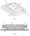
- Figure 3 shows schematically a perspective view of one of the seal segments 28.
- the segment 28 has a lightly curved, plate-like, rectangular shape.
- a radially outer, body portion 34 of the segment 28 is formed from continuous fibre reinforced ceramic matrix composite, as discussed in more detail below.
- An abradable coating 35 comprising hollow ceramic spheres in a ceramic matrix, as disclosed in EP 0751104 is formed on the radially inward facing surface of the body portion 34.
- the abradable coating 35 also acts as a thermal barrier coating.
- the gasket-type sealing ring 33 (not shown in Figure 3 ) runs around the edges of the radially outer surface of the body portion 34. The arrows indicate the general direction of cooling air flow over the radially outer surface.
- Respective slots 36 extend in the circumferential direction along the front and rear sides of the body portion 34.
- the backing plate 29 can be machined as a single piece, and then cut in (typically two) pieces.
- Each seal segment 28 can be mounted to the backing plate by sliding in the circumferential direction onto a respective cut piece of the back plate. The cut pieces are then joined back together again.
- Figure 4 shows schematically a cross-section through the body portion 34, which is formed from a number of sub-components.
- a central sub-component 37 has the reinforcing fibres of the composite arranged in plys that are substantially parallel to the radially inner surface of the body portion 34, but are lightly dished towards that surface.
- To the front and rear sides of the central sub-component 37 are respective C-section sub-components 38 in which the reinforcing fibres wrap around the respective slot 36 so that, at the base of each slot, the fibres are parallel to the surface of the body portion.
- An optional inner sub-component 39 in which the reinforcing fibres are parallel to the radially inward facing surface of the body portion 34, can extend the radially over the radially inner surfaces of the central sub-component 37 and the C-section sub-components 38.
- dished it is meant that the plys are bent or domed towards the radially inner surface towards the centre of the central sub-component.
- the benefit of providing lightly dished plys is that it allows the fibres which are located at the radial centre of the component to extend across the full width of the component without being interrupted by the C-section sub-components.
- the radius of the bend shown in Figure 4 is constant across the width of the component but the skilled person will appreciate that this might not be the case in other embodiments.
- the central sub-component 37 includes recesses in which the C-section sub-components are located.
- the inner surface of the recess corresponds to the outer surface of the C-section sub-component such that the two meet at an interface surface.
- the inner surface of the recess includes a radially inclined portion which slopes relative the radially inward facing surface of the body, and a curved portion which accommodates the curvature of the C-section bend.
- the slope of the radially inclined slope is tangential to the ply which intersects the C-section sub-component where the junction between the radially inclined portion and curved portion. Providing a tangential line like this allows the plys of the dished central sub-component to extend fully from radially outwards of the C-section sub-component to the opposing side whilst maximising the thickness of the C-section sub-component.
- Each sub-component 37, 38, 39 can be produced by using an oxide ceramic matrix composite system by stacking successive plys formed from a cloth of woven continuous reinforcement. As each ply is stacked it is covered in a slurry containing a binder, water and ceramic. The stacked plys are pressed to remove water, the binder acting to form a self-supporting green form. The green is then heated in a furnace to drive off residual moisture and sinter the ceramic particles to form the surrounding matrix.
- Curved or straight-sided blocks can readily be formed in this way.
- the overall shape of the sub-components and features, such as a location recess 40 for sealing ring 33, can be produced by subsequent machining where required.
- the reinforcement fibres can be Nextel720TM alumina silicate fibres available from 3M
- the ceramic particles can be alumina particles or a mixture of alumina and silicate particles.
- the separately produced sub- components are bonded together using ceramic cement.
- the invention is applicably to other ceramic matrix composite systems, such as the so-called SiC/SiC, and these will be manufactured accordingly.
- the sub-components can be formed into the required shape from the SiC fibres and temporarily attached together prior to a chemical vapour infiltration which acts to bond the sub-components together.
- the abradable coating 35 can be moulded directly on the body portion 34, or cast separately to the required shape and then glued to the body portion 34, as discussed in EP 0751104 .
- Figure 5(a) shows, on a cross-section through a modelled seal segment, the inter-laminar tensile stress, as calculated from a finite element stress analysis, resulting from a representative reaction load R applied at the radially upper surface of a slot at the right hand side of the segment and a representative pressure load P applied over the radially outer surface of the segment.
- the segment is notionally formed by a simple stacking 2D plys, and thus corresponds to a conventional segment in which there is no attempt to wrap the reinforcing fibres of the composite around the slot at the right hand side. As a consequence, the plys end abruptly at the base of the slot.
- the peak stress (X MPa) at the base of the slot reaches a value which is too high for this type of material and could lead to crack growth as indicated by the arrow pointing from the base of the slot.
- Figure 5(b) shows, on a corresponding cross-section through a modelled seal segment, the inter-laminar tensile stress resulting from the same loads R, P, again as calculated from a finite element stress analysis.
- the segment has the same external geometry as the segment of Figure 5(a) , but in this case the segment is formed from sub-components 37, 38, 39, whereby the reinforcing fibres of the composite wrap around the slot.
- the bulk stresses in the segment are again acceptable.
- the peak stress at the base of the slot only reaches a more acceptable X/2 MPa.
- the direction of the fibres at the base of the slot would tend to lie across the propagation path of any incipient crack, making it difficult for the crack to grow.
Landscapes
- Engineering & Computer Science (AREA)
- Mechanical Engineering (AREA)
- General Engineering & Computer Science (AREA)
- Chemical & Material Sciences (AREA)
- Materials Engineering (AREA)
- Ceramic Engineering (AREA)
- Turbine Rotor Nozzle Sealing (AREA)
Applications Claiming Priority (1)
| Application Number | Priority Date | Filing Date | Title |
|---|---|---|---|
| GBGB1305702.1A GB201305702D0 (en) | 2013-03-28 | 2013-03-28 | Seal segment |
Publications (3)
| Publication Number | Publication Date |
|---|---|
| EP2784272A2 true EP2784272A2 (fr) | 2014-10-01 |
| EP2784272A3 EP2784272A3 (fr) | 2017-08-09 |
| EP2784272B1 EP2784272B1 (fr) | 2019-03-06 |
Family
ID=48444936
Family Applications (1)
| Application Number | Title | Priority Date | Filing Date |
|---|---|---|---|
| EP14161521.1A Active EP2784272B1 (fr) | 2013-03-28 | 2014-03-25 | Segment d'étanchéité d'une turbine à gaz à matériau composite de matrice céramique |
Country Status (3)
| Country | Link |
|---|---|
| US (1) | US9546562B2 (fr) |
| EP (1) | EP2784272B1 (fr) |
| GB (1) | GB201305702D0 (fr) |
Cited By (5)
| Publication number | Priority date | Publication date | Assignee | Title |
|---|---|---|---|---|
| EP3208428A1 (fr) * | 2016-02-22 | 2017-08-23 | MTU Aero Engines GmbH | Systeme d'etancheification en matiere composite en fibres a ceramique |
| EP3255252A1 (fr) * | 2016-06-07 | 2017-12-13 | United Technologies Corporation | Joint d'air extérieur d'aube constitué d'un composite à matrice céramique |
| CN110005481A (zh) * | 2017-11-13 | 2019-07-12 | 通用电气公司 | 使用机械接头的cmc构件和制作 |
| EP3575558A1 (fr) * | 2018-06-01 | 2019-12-04 | United Technologies Corporation | Ensemble d'étanchéité pour moteurs de turbine à gaz |
| US11686208B2 (en) | 2020-02-06 | 2023-06-27 | Rolls-Royce Corporation | Abrasive coating for high-temperature mechanical systems |
Families Citing this family (17)
| Publication number | Priority date | Publication date | Assignee | Title |
|---|---|---|---|---|
| JP5569194B2 (ja) * | 2010-07-02 | 2014-08-13 | 株式会社Ihi | シュラウドセグメントの製造方法 |
| US9726043B2 (en) | 2011-12-15 | 2017-08-08 | General Electric Company | Mounting apparatus for low-ductility turbine shroud |
| CN105612313B (zh) | 2013-05-17 | 2017-11-21 | 通用电气公司 | 燃气涡轮机的cmc护罩支撑系统 |
| JP6529013B2 (ja) | 2013-12-12 | 2019-06-12 | ゼネラル・エレクトリック・カンパニイ | Cmcシュラウド支持システム |
| EP3155231B1 (fr) | 2014-06-12 | 2019-07-03 | General Electric Company | Ensemble dispositif de suspension de carénage |
| JP6574208B2 (ja) | 2014-06-12 | 2019-09-11 | ゼネラル・エレクトリック・カンパニイ | シュラウドハンガアセンブリ |
| EP3155236A1 (fr) | 2014-06-12 | 2017-04-19 | General Electric Company | Ensemble de suspension de carénage |
| US9874104B2 (en) | 2015-02-27 | 2018-01-23 | General Electric Company | Method and system for a ceramic matrix composite shroud hanger assembly |
| US10703680B2 (en) * | 2015-05-25 | 2020-07-07 | Apple Inc. | Fiber-reinforced ceramic matrix composite for electronic devices |
| WO2017031043A1 (fr) | 2015-08-19 | 2017-02-23 | Henkel IP & Holding GmbH | Fluxage de compositions de remplissage |
| JP6167158B2 (ja) | 2015-12-09 | 2017-07-19 | 三菱日立パワーシステムズ株式会社 | シール構造及びターボ機械 |
| US10801349B2 (en) | 2017-08-25 | 2020-10-13 | Raytheon Technologies Corporation | Ceramic matrix composite blade outer air seal |
| US10822981B2 (en) | 2017-10-30 | 2020-11-03 | General Electric Company | Variable guide vane sealing |
| US10739675B2 (en) | 2018-05-31 | 2020-08-11 | Canon Kabushiki Kaisha | Systems and methods for detection of and compensation for malfunctioning droplet dispensing nozzles |
| US10815821B2 (en) | 2018-08-31 | 2020-10-27 | General Electric Company | Variable airfoil with sealed flowpath |
| US11686210B2 (en) | 2021-03-24 | 2023-06-27 | General Electric Company | Component assembly for variable airfoil systems |
| US11732598B2 (en) * | 2021-12-17 | 2023-08-22 | Rolls-Royce Corporation | Ceramic matrix composite turbine shroud shaped for minimizing abradable coating layer |
Family Cites Families (9)
| Publication number | Priority date | Publication date | Assignee | Title |
|---|---|---|---|---|
| GB9513252D0 (en) | 1995-06-29 | 1995-09-06 | Rolls Royce Plc | An abradable composition |
| US6139257A (en) * | 1998-03-23 | 2000-10-31 | General Electric Company | Shroud cooling assembly for gas turbine engine |
| JP2004036443A (ja) * | 2002-07-02 | 2004-02-05 | Ishikawajima Harima Heavy Ind Co Ltd | ガスタービンシュラウド構造 |
| US6758653B2 (en) * | 2002-09-09 | 2004-07-06 | Siemens Westinghouse Power Corporation | Ceramic matrix composite component for a gas turbine engine |
| US7374395B2 (en) * | 2005-07-19 | 2008-05-20 | Pratt & Whitney Canada Corp. | Turbine shroud segment feather seal located in radial shroud legs |
| GB0703827D0 (en) * | 2007-02-28 | 2007-04-11 | Rolls Royce Plc | Rotor seal segment |
| ES2398727T3 (es) * | 2009-03-09 | 2013-03-21 | Snecma | Conjunto de anillo de turbina |
| US8226361B2 (en) * | 2009-07-08 | 2012-07-24 | General Electric Company | Composite article and support frame assembly |
| JP5569194B2 (ja) | 2010-07-02 | 2014-08-13 | 株式会社Ihi | シュラウドセグメントの製造方法 |
-
2013
- 2013-03-28 GB GBGB1305702.1A patent/GB201305702D0/en not_active Ceased
-
2014
- 2014-03-25 US US14/224,952 patent/US9546562B2/en active Active
- 2014-03-25 EP EP14161521.1A patent/EP2784272B1/fr active Active
Cited By (9)
| Publication number | Priority date | Publication date | Assignee | Title |
|---|---|---|---|---|
| EP3208428A1 (fr) * | 2016-02-22 | 2017-08-23 | MTU Aero Engines GmbH | Systeme d'etancheification en matiere composite en fibres a ceramique |
| US10151209B2 (en) | 2016-02-22 | 2018-12-11 | MTU Aero Engines AG | Sealing system made of ceramic fiber composite materials |
| EP3255252A1 (fr) * | 2016-06-07 | 2017-12-13 | United Technologies Corporation | Joint d'air extérieur d'aube constitué d'un composite à matrice céramique |
| US10196918B2 (en) | 2016-06-07 | 2019-02-05 | United Technologies Corporation | Blade outer air seal made of ceramic matrix composite |
| EP3611349A1 (fr) * | 2016-06-07 | 2020-02-19 | United Technologies Corporation | Joint d'air extérieur d'aube constitué d'un composite à matrice céramique |
| CN110005481A (zh) * | 2017-11-13 | 2019-07-12 | 通用电气公司 | 使用机械接头的cmc构件和制作 |
| EP3575558A1 (fr) * | 2018-06-01 | 2019-12-04 | United Technologies Corporation | Ensemble d'étanchéité pour moteurs de turbine à gaz |
| US11035243B2 (en) | 2018-06-01 | 2021-06-15 | Raytheon Technologies Corporation | Seal assembly for gas turbine engines |
| US11686208B2 (en) | 2020-02-06 | 2023-06-27 | Rolls-Royce Corporation | Abrasive coating for high-temperature mechanical systems |
Also Published As
| Publication number | Publication date |
|---|---|
| GB201305702D0 (en) | 2013-05-15 |
| US20140294571A1 (en) | 2014-10-02 |
| EP2784272B1 (fr) | 2019-03-06 |
| US9546562B2 (en) | 2017-01-17 |
| EP2784272A3 (fr) | 2017-08-09 |
Similar Documents
| Publication | Publication Date | Title |
|---|---|---|
| US9546562B2 (en) | Seal segment | |
| EP2775103B1 (fr) | Composant en CMC pour moteur à turbine | |
| EP2728125A1 (fr) | Procédé de formage de composant en composite à matrice céramique et composant de moteur à turbine à gaz en composite à matrice céramique associé | |
| EP2784269A1 (fr) | Section de paroi de canal d'écoulement annulaire de gaz de travail d'un moteur à turbine à gaz, virole interne et moteur à turbine à gaz associés | |
| US9581038B2 (en) | Seal segment | |
| US11466580B2 (en) | CMC nozzle with interlocking mechanical joint and fabrication | |
| US20230304408A1 (en) | Component for a gas turbine engine | |
| US8118546B2 (en) | Grid ceramic matrix composite structure for gas turbine shroud ring segment | |
| US11441436B2 (en) | Flow path assemblies for gas turbine engines and assembly methods therefore | |
| US10132170B2 (en) | Systems and method for a composite blade with fillet transition | |
| CN108730039B (zh) | 用于燃气涡轮发动机的涡轮喷嘴段和系统 | |
| US10221712B2 (en) | Seal for hardware segments | |
| CN110439626B (zh) | 用于叉指转子的复合翼型组件 | |
| EP3049626B1 (fr) | Pale en cmc à bord de fuite pointu et sa procédé de fabrication | |
| CN110439625B (zh) | 用于叉指转子的复合翼型组件 | |
| CN110863865B (zh) | 涡轮叶片末梢围带 | |
| US20190170013A1 (en) | Discontinuous Molded Tape Wear Interface for Composite Components | |
| EP3572625B1 (fr) | Joint pour éléments de virole de turbine en céramique | |
| CN108730035B (zh) | 用于燃气涡轮发动机的流径组件和装配该组件的方法 | |
| EP4119772A1 (fr) | Ensemble surface portante comportant des anneaux en composite renforcé de fibres et une fente de sortie dentée |
Legal Events
| Date | Code | Title | Description |
|---|---|---|---|
| 17P | Request for examination filed |
Effective date: 20140325 |
|
| AK | Designated contracting states |
Kind code of ref document: A2 Designated state(s): AL AT BE BG CH CY CZ DE DK EE ES FI FR GB GR HR HU IE IS IT LI LT LU LV MC MK MT NL NO PL PT RO RS SE SI SK SM TR |
|
| AX | Request for extension of the european patent |
Extension state: BA ME |
|
| PUAI | Public reference made under article 153(3) epc to a published international application that has entered the european phase |
Free format text: ORIGINAL CODE: 0009012 |
|
| RAP1 | Party data changed (applicant data changed or rights of an application transferred) |
Owner name: ROLLS-ROYCE PLC |
|
| PUAL | Search report despatched |
Free format text: ORIGINAL CODE: 0009013 |
|
| AK | Designated contracting states |
Kind code of ref document: A3 Designated state(s): AL AT BE BG CH CY CZ DE DK EE ES FI FR GB GR HR HU IE IS IT LI LT LU LV MC MK MT NL NO PL PT RO RS SE SI SK SM TR |
|
| AX | Request for extension of the european patent |
Extension state: BA ME |
|
| RIC1 | Information provided on ipc code assigned before grant |
Ipc: F01D 11/08 20060101ALI20170706BHEP Ipc: F01D 11/12 20060101ALI20170706BHEP Ipc: F01D 9/04 20060101ALI20170706BHEP Ipc: F01D 25/00 20060101AFI20170706BHEP Ipc: F01D 5/28 20060101ALI20170706BHEP |
|
| STAA | Information on the status of an ep patent application or granted ep patent |
Free format text: STATUS: REQUEST FOR EXAMINATION WAS MADE |
|
| R17P | Request for examination filed (corrected) |
Effective date: 20180208 |
|
| RBV | Designated contracting states (corrected) |
Designated state(s): AL AT BE BG CH CY CZ DE DK EE ES FI FR GB GR HR HU IE IS IT LI LT LU LV MC MK MT NL NO PL PT RO RS SE SI SK SM TR |
|
| GRAP | Despatch of communication of intention to grant a patent |
Free format text: ORIGINAL CODE: EPIDOSNIGR1 |
|
| STAA | Information on the status of an ep patent application or granted ep patent |
Free format text: STATUS: GRANT OF PATENT IS INTENDED |
|
| INTG | Intention to grant announced |
Effective date: 20181128 |
|
| GRAS | Grant fee paid |
Free format text: ORIGINAL CODE: EPIDOSNIGR3 |
|
| GRAA | (expected) grant |
Free format text: ORIGINAL CODE: 0009210 |
|
| STAA | Information on the status of an ep patent application or granted ep patent |
Free format text: STATUS: THE PATENT HAS BEEN GRANTED |
|
| AK | Designated contracting states |
Kind code of ref document: B1 Designated state(s): AL AT BE BG CH CY CZ DE DK EE ES FI FR GB GR HR HU IE IS IT LI LT LU LV MC MK MT NL NO PL PT RO RS SE SI SK SM TR |
|
| REG | Reference to a national code |
Ref country code: GB Ref legal event code: FG4D |
|
| REG | Reference to a national code |
Ref country code: CH Ref legal event code: EP Ref country code: AT Ref legal event code: REF Ref document number: 1104827 Country of ref document: AT Kind code of ref document: T Effective date: 20190315 |
|
| REG | Reference to a national code |
Ref country code: DE Ref legal event code: R096 Ref document number: 602014042190 Country of ref document: DE |
|
| REG | Reference to a national code |
Ref country code: IE Ref legal event code: FG4D |
|
| REG | Reference to a national code |
Ref country code: NL Ref legal event code: MP Effective date: 20190306 |
|
| REG | Reference to a national code |
Ref country code: LT Ref legal event code: MG4D |
|
| PG25 | Lapsed in a contracting state [announced via postgrant information from national office to epo] |
Ref country code: SE Free format text: LAPSE BECAUSE OF FAILURE TO SUBMIT A TRANSLATION OF THE DESCRIPTION OR TO PAY THE FEE WITHIN THE PRESCRIBED TIME-LIMIT Effective date: 20190306 Ref country code: FI Free format text: LAPSE BECAUSE OF FAILURE TO SUBMIT A TRANSLATION OF THE DESCRIPTION OR TO PAY THE FEE WITHIN THE PRESCRIBED TIME-LIMIT Effective date: 20190306 Ref country code: NO Free format text: LAPSE BECAUSE OF FAILURE TO SUBMIT A TRANSLATION OF THE DESCRIPTION OR TO PAY THE FEE WITHIN THE PRESCRIBED TIME-LIMIT Effective date: 20190606 Ref country code: LT Free format text: LAPSE BECAUSE OF FAILURE TO SUBMIT A TRANSLATION OF THE DESCRIPTION OR TO PAY THE FEE WITHIN THE PRESCRIBED TIME-LIMIT Effective date: 20190306 |
|
| PG25 | Lapsed in a contracting state [announced via postgrant information from national office to epo] |
Ref country code: GR Free format text: LAPSE BECAUSE OF FAILURE TO SUBMIT A TRANSLATION OF THE DESCRIPTION OR TO PAY THE FEE WITHIN THE PRESCRIBED TIME-LIMIT Effective date: 20190607 Ref country code: BG Free format text: LAPSE BECAUSE OF FAILURE TO SUBMIT A TRANSLATION OF THE DESCRIPTION OR TO PAY THE FEE WITHIN THE PRESCRIBED TIME-LIMIT Effective date: 20190606 Ref country code: HR Free format text: LAPSE BECAUSE OF FAILURE TO SUBMIT A TRANSLATION OF THE DESCRIPTION OR TO PAY THE FEE WITHIN THE PRESCRIBED TIME-LIMIT Effective date: 20190306 Ref country code: NL Free format text: LAPSE BECAUSE OF FAILURE TO SUBMIT A TRANSLATION OF THE DESCRIPTION OR TO PAY THE FEE WITHIN THE PRESCRIBED TIME-LIMIT Effective date: 20190306 Ref country code: RS Free format text: LAPSE BECAUSE OF FAILURE TO SUBMIT A TRANSLATION OF THE DESCRIPTION OR TO PAY THE FEE WITHIN THE PRESCRIBED TIME-LIMIT Effective date: 20190306 Ref country code: LV Free format text: LAPSE BECAUSE OF FAILURE TO SUBMIT A TRANSLATION OF THE DESCRIPTION OR TO PAY THE FEE WITHIN THE PRESCRIBED TIME-LIMIT Effective date: 20190306 |
|
| REG | Reference to a national code |
Ref country code: AT Ref legal event code: MK05 Ref document number: 1104827 Country of ref document: AT Kind code of ref document: T Effective date: 20190306 |
|
| PG25 | Lapsed in a contracting state [announced via postgrant information from national office to epo] |
Ref country code: SK Free format text: LAPSE BECAUSE OF FAILURE TO SUBMIT A TRANSLATION OF THE DESCRIPTION OR TO PAY THE FEE WITHIN THE PRESCRIBED TIME-LIMIT Effective date: 20190306 Ref country code: RO Free format text: LAPSE BECAUSE OF FAILURE TO SUBMIT A TRANSLATION OF THE DESCRIPTION OR TO PAY THE FEE WITHIN THE PRESCRIBED TIME-LIMIT Effective date: 20190306 Ref country code: CZ Free format text: LAPSE BECAUSE OF FAILURE TO SUBMIT A TRANSLATION OF THE DESCRIPTION OR TO PAY THE FEE WITHIN THE PRESCRIBED TIME-LIMIT Effective date: 20190306 Ref country code: EE Free format text: LAPSE BECAUSE OF FAILURE TO SUBMIT A TRANSLATION OF THE DESCRIPTION OR TO PAY THE FEE WITHIN THE PRESCRIBED TIME-LIMIT Effective date: 20190306 Ref country code: IT Free format text: LAPSE BECAUSE OF FAILURE TO SUBMIT A TRANSLATION OF THE DESCRIPTION OR TO PAY THE FEE WITHIN THE PRESCRIBED TIME-LIMIT Effective date: 20190306 Ref country code: ES Free format text: LAPSE BECAUSE OF FAILURE TO SUBMIT A TRANSLATION OF THE DESCRIPTION OR TO PAY THE FEE WITHIN THE PRESCRIBED TIME-LIMIT Effective date: 20190306 Ref country code: AL Free format text: LAPSE BECAUSE OF FAILURE TO SUBMIT A TRANSLATION OF THE DESCRIPTION OR TO PAY THE FEE WITHIN THE PRESCRIBED TIME-LIMIT Effective date: 20190306 Ref country code: PT Free format text: LAPSE BECAUSE OF FAILURE TO SUBMIT A TRANSLATION OF THE DESCRIPTION OR TO PAY THE FEE WITHIN THE PRESCRIBED TIME-LIMIT Effective date: 20190706 |
|
| REG | Reference to a national code |
Ref country code: CH Ref legal event code: PL |
|
| PG25 | Lapsed in a contracting state [announced via postgrant information from national office to epo] |
Ref country code: LU Free format text: LAPSE BECAUSE OF NON-PAYMENT OF DUE FEES Effective date: 20190325 Ref country code: SM Free format text: LAPSE BECAUSE OF FAILURE TO SUBMIT A TRANSLATION OF THE DESCRIPTION OR TO PAY THE FEE WITHIN THE PRESCRIBED TIME-LIMIT Effective date: 20190306 Ref country code: PL Free format text: LAPSE BECAUSE OF FAILURE TO SUBMIT A TRANSLATION OF THE DESCRIPTION OR TO PAY THE FEE WITHIN THE PRESCRIBED TIME-LIMIT Effective date: 20190306 |
|
| REG | Reference to a national code |
Ref country code: BE Ref legal event code: MM Effective date: 20190331 |
|
| REG | Reference to a national code |
Ref country code: DE Ref legal event code: R097 Ref document number: 602014042190 Country of ref document: DE |
|
| PG25 | Lapsed in a contracting state [announced via postgrant information from national office to epo] |
Ref country code: AT Free format text: LAPSE BECAUSE OF FAILURE TO SUBMIT A TRANSLATION OF THE DESCRIPTION OR TO PAY THE FEE WITHIN THE PRESCRIBED TIME-LIMIT Effective date: 20190306 Ref country code: IS Free format text: LAPSE BECAUSE OF FAILURE TO SUBMIT A TRANSLATION OF THE DESCRIPTION OR TO PAY THE FEE WITHIN THE PRESCRIBED TIME-LIMIT Effective date: 20190706 |
|
| PLBE | No opposition filed within time limit |
Free format text: ORIGINAL CODE: 0009261 |
|
| STAA | Information on the status of an ep patent application or granted ep patent |
Free format text: STATUS: NO OPPOSITION FILED WITHIN TIME LIMIT |
|
| PG25 | Lapsed in a contracting state [announced via postgrant information from national office to epo] |
Ref country code: LI Free format text: LAPSE BECAUSE OF NON-PAYMENT OF DUE FEES Effective date: 20190331 Ref country code: CH Free format text: LAPSE BECAUSE OF NON-PAYMENT OF DUE FEES Effective date: 20190331 Ref country code: DK Free format text: LAPSE BECAUSE OF FAILURE TO SUBMIT A TRANSLATION OF THE DESCRIPTION OR TO PAY THE FEE WITHIN THE PRESCRIBED TIME-LIMIT Effective date: 20190306 Ref country code: IE Free format text: LAPSE BECAUSE OF NON-PAYMENT OF DUE FEES Effective date: 20190325 Ref country code: MC Free format text: LAPSE BECAUSE OF FAILURE TO SUBMIT A TRANSLATION OF THE DESCRIPTION OR TO PAY THE FEE WITHIN THE PRESCRIBED TIME-LIMIT Effective date: 20190306 |
|
| 26N | No opposition filed |
Effective date: 20191209 |
|
| PG25 | Lapsed in a contracting state [announced via postgrant information from national office to epo] |
Ref country code: SI Free format text: LAPSE BECAUSE OF FAILURE TO SUBMIT A TRANSLATION OF THE DESCRIPTION OR TO PAY THE FEE WITHIN THE PRESCRIBED TIME-LIMIT Effective date: 20190306 Ref country code: BE Free format text: LAPSE BECAUSE OF NON-PAYMENT OF DUE FEES Effective date: 20190331 |
|
| PG25 | Lapsed in a contracting state [announced via postgrant information from national office to epo] |
Ref country code: TR Free format text: LAPSE BECAUSE OF FAILURE TO SUBMIT A TRANSLATION OF THE DESCRIPTION OR TO PAY THE FEE WITHIN THE PRESCRIBED TIME-LIMIT Effective date: 20190306 |
|
| PG25 | Lapsed in a contracting state [announced via postgrant information from national office to epo] |
Ref country code: MT Free format text: LAPSE BECAUSE OF NON-PAYMENT OF DUE FEES Effective date: 20190325 |
|
| PG25 | Lapsed in a contracting state [announced via postgrant information from national office to epo] |
Ref country code: CY Free format text: LAPSE BECAUSE OF FAILURE TO SUBMIT A TRANSLATION OF THE DESCRIPTION OR TO PAY THE FEE WITHIN THE PRESCRIBED TIME-LIMIT Effective date: 20190306 |
|
| PG25 | Lapsed in a contracting state [announced via postgrant information from national office to epo] |
Ref country code: HU Free format text: LAPSE BECAUSE OF FAILURE TO SUBMIT A TRANSLATION OF THE DESCRIPTION OR TO PAY THE FEE WITHIN THE PRESCRIBED TIME-LIMIT; INVALID AB INITIO Effective date: 20140325 |
|
| PG25 | Lapsed in a contracting state [announced via postgrant information from national office to epo] |
Ref country code: MK Free format text: LAPSE BECAUSE OF FAILURE TO SUBMIT A TRANSLATION OF THE DESCRIPTION OR TO PAY THE FEE WITHIN THE PRESCRIBED TIME-LIMIT Effective date: 20190306 |
|
| PGFP | Annual fee paid to national office [announced via postgrant information from national office to epo] |
Ref country code: FR Payment date: 20230323 Year of fee payment: 10 |
|
| PGFP | Annual fee paid to national office [announced via postgrant information from national office to epo] |
Ref country code: GB Payment date: 20230321 Year of fee payment: 10 Ref country code: DE Payment date: 20230328 Year of fee payment: 10 |
|
| P01 | Opt-out of the competence of the unified patent court (upc) registered |
Effective date: 20230528 |