EP3575342A1 - Method and system for laser sintering with pretreated material - Google Patents
Method and system for laser sintering with pretreated material Download PDFInfo
- Publication number
- EP3575342A1 EP3575342A1 EP19182632.0A EP19182632A EP3575342A1 EP 3575342 A1 EP3575342 A1 EP 3575342A1 EP 19182632 A EP19182632 A EP 19182632A EP 3575342 A1 EP3575342 A1 EP 3575342A1
- Authority
- EP
- European Patent Office
- Prior art keywords
- temperature
- thermoplastic polymer
- polyamide
- melting
- specified
- Prior art date
- Legal status (The legal status is an assumption and is not a legal conclusion. Google has not performed a legal analysis and makes no representation as to the accuracy of the status listed.)
- Ceased
Links
Images


Classifications
-
- C—CHEMISTRY; METALLURGY
- C08—ORGANIC MACROMOLECULAR COMPOUNDS; THEIR PREPARATION OR CHEMICAL WORKING-UP; COMPOSITIONS BASED THEREON
- C08G—MACROMOLECULAR COMPOUNDS OBTAINED OTHERWISE THAN BY REACTIONS ONLY INVOLVING UNSATURATED CARBON-TO-CARBON BONDS
- C08G69/00—Macromolecular compounds obtained by reactions forming a carboxylic amide link in the main chain of the macromolecule
- C08G69/02—Polyamides derived from amino-carboxylic acids or from polyamines and polycarboxylic acids
- C08G69/08—Polyamides derived from amino-carboxylic acids or from polyamines and polycarboxylic acids derived from amino-carboxylic acids
- C08G69/14—Lactams
-
- B—PERFORMING OPERATIONS; TRANSPORTING
- B29—WORKING OF PLASTICS; WORKING OF SUBSTANCES IN A PLASTIC STATE IN GENERAL
- B29B—PREPARATION OR PRETREATMENT OF THE MATERIAL TO BE SHAPED; MAKING GRANULES OR PREFORMS; RECOVERY OF PLASTICS OR OTHER CONSTITUENTS OF WASTE MATERIAL CONTAINING PLASTICS
- B29B13/00—Conditioning or physical treatment of the material to be shaped
- B29B13/02—Conditioning or physical treatment of the material to be shaped by heating
- B29B13/021—Heat treatment of powders
-
- B—PERFORMING OPERATIONS; TRANSPORTING
- B33—ADDITIVE MANUFACTURING TECHNOLOGY
- B33Y—ADDITIVE MANUFACTURING, i.e. MANUFACTURING OF THREE-DIMENSIONAL [3-D] OBJECTS BY ADDITIVE DEPOSITION, ADDITIVE AGGLOMERATION OR ADDITIVE LAYERING, e.g. BY 3-D PRINTING, STEREOLITHOGRAPHY OR SELECTIVE LASER SINTERING
- B33Y70/00—Materials specially adapted for additive manufacturing
-
- C—CHEMISTRY; METALLURGY
- C08—ORGANIC MACROMOLECULAR COMPOUNDS; THEIR PREPARATION OR CHEMICAL WORKING-UP; COMPOSITIONS BASED THEREON
- C08F—MACROMOLECULAR COMPOUNDS OBTAINED BY REACTIONS ONLY INVOLVING CARBON-TO-CARBON UNSATURATED BONDS
- C08F10/00—Homopolymers and copolymers of unsaturated aliphatic hydrocarbons having only one carbon-to-carbon double bond
- C08F10/02—Ethene
-
- C—CHEMISTRY; METALLURGY
- C08—ORGANIC MACROMOLECULAR COMPOUNDS; THEIR PREPARATION OR CHEMICAL WORKING-UP; COMPOSITIONS BASED THEREON
- C08F—MACROMOLECULAR COMPOUNDS OBTAINED BY REACTIONS ONLY INVOLVING CARBON-TO-CARBON UNSATURATED BONDS
- C08F10/00—Homopolymers and copolymers of unsaturated aliphatic hydrocarbons having only one carbon-to-carbon double bond
- C08F10/04—Monomers containing three or four carbon atoms
- C08F10/06—Propene
-
- C—CHEMISTRY; METALLURGY
- C08—ORGANIC MACROMOLECULAR COMPOUNDS; THEIR PREPARATION OR CHEMICAL WORKING-UP; COMPOSITIONS BASED THEREON
- C08G—MACROMOLECULAR COMPOUNDS OBTAINED OTHERWISE THAN BY REACTIONS ONLY INVOLVING UNSATURATED CARBON-TO-CARBON BONDS
- C08G69/00—Macromolecular compounds obtained by reactions forming a carboxylic amide link in the main chain of the macromolecule
- C08G69/02—Polyamides derived from amino-carboxylic acids or from polyamines and polycarboxylic acids
- C08G69/26—Polyamides derived from amino-carboxylic acids or from polyamines and polycarboxylic acids derived from polyamines and polycarboxylic acids
- C08G69/265—Polyamides derived from amino-carboxylic acids or from polyamines and polycarboxylic acids derived from polyamines and polycarboxylic acids from at least two different diamines or at least two different dicarboxylic acids
-
- C—CHEMISTRY; METALLURGY
- C08—ORGANIC MACROMOLECULAR COMPOUNDS; THEIR PREPARATION OR CHEMICAL WORKING-UP; COMPOSITIONS BASED THEREON
- C08G—MACROMOLECULAR COMPOUNDS OBTAINED OTHERWISE THAN BY REACTIONS ONLY INVOLVING UNSATURATED CARBON-TO-CARBON BONDS
- C08G85/00—General processes for preparing compounds provided for in this subclass
- C08G85/002—Post-polymerisation treatment
-
- C—CHEMISTRY; METALLURGY
- C08—ORGANIC MACROMOLECULAR COMPOUNDS; THEIR PREPARATION OR CHEMICAL WORKING-UP; COMPOSITIONS BASED THEREON
- C08L—COMPOSITIONS OF MACROMOLECULAR COMPOUNDS
- C08L77/00—Compositions of polyamides obtained by reactions forming a carboxylic amide link in the main chain; Compositions of derivatives of such polymers
- C08L77/02—Polyamides derived from omega-amino carboxylic acids or from lactams thereof
-
- C—CHEMISTRY; METALLURGY
- C08—ORGANIC MACROMOLECULAR COMPOUNDS; THEIR PREPARATION OR CHEMICAL WORKING-UP; COMPOSITIONS BASED THEREON
- C08L—COMPOSITIONS OF MACROMOLECULAR COMPOUNDS
- C08L77/00—Compositions of polyamides obtained by reactions forming a carboxylic amide link in the main chain; Compositions of derivatives of such polymers
- C08L77/06—Polyamides derived from polyamines and polycarboxylic acids
-
- B—PERFORMING OPERATIONS; TRANSPORTING
- B29—WORKING OF PLASTICS; WORKING OF SUBSTANCES IN A PLASTIC STATE IN GENERAL
- B29C—SHAPING OR JOINING OF PLASTICS; SHAPING OF MATERIAL IN A PLASTIC STATE, NOT OTHERWISE PROVIDED FOR; AFTER-TREATMENT OF THE SHAPED PRODUCTS, e.g. REPAIRING
- B29C64/00—Additive manufacturing, i.e. manufacturing of three-dimensional [3D] objects by additive deposition, additive agglomeration or additive layering, e.g. by 3D printing, stereolithography or selective laser sintering
- B29C64/10—Processes of additive manufacturing
- B29C64/141—Processes of additive manufacturing using only solid materials
- B29C64/153—Processes of additive manufacturing using only solid materials using layers of powder being selectively joined, e.g. by selective laser sintering or melting
Landscapes
- Chemical & Material Sciences (AREA)
- Chemical Kinetics & Catalysis (AREA)
- Medicinal Chemistry (AREA)
- Polymers & Plastics (AREA)
- Organic Chemistry (AREA)
- Health & Medical Sciences (AREA)
- Engineering & Computer Science (AREA)
- Manufacturing & Machinery (AREA)
- Materials Engineering (AREA)
- Physics & Mathematics (AREA)
- Mechanical Engineering (AREA)
- Thermal Sciences (AREA)
- Processing And Handling Of Plastics And Other Materials For Molding In General (AREA)
- Processes Of Treating Macromolecular Substances (AREA)
- Treatments Of Macromolecular Shaped Articles (AREA)
Abstract
Description
- The disclosures herein relate in general to powder based additive manufacturing, and in particular to a method and system for heat induced sintering or melting with pretreated material for additive manufacturing.
- A commercial used method for powder based additive manufacturing is selective laser sintering ("SLS") processing. This process is useful for solid freeform fabrication of three-dimensional objects. For SLS processing, viable materials include polymers (e.g., nylon type materials). Nevertheless, a wider range of such materials is desired.
-
-
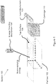
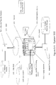
FIG. 1 is a perspective schematic view of an SLS system of the illustrative embodiment (System 100). -
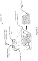
FIG. 2 is a perspective schematic cutaway view of the system ofFIG. 1 . -
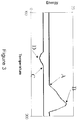
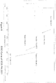
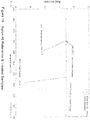
FIG. 3 is a first example differential scanning calorimetry ("DSC") trace of a first material, showing a melting curve and a recrystallization curve for the first material. -
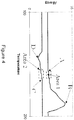
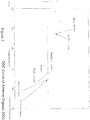
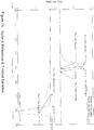
FIG. 4 is a second example DSC trace of a second material, showing a melting curve and a recrystallization curve for the second material. -
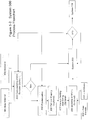
FIG. 5-1 ,5-2 ,5-3 , and5-4 illustrate a treatment system of the illustrative embodiment (System 500). -
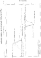
FIG. 6 is an example DSC trace of a sample of EVONIK nylon-12 material. -
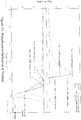
FIG. 7 is an example DSC trace of a sample of ARKEMA ORGASOL 2003 nylon-12 material. -
FIG. 8 is an example DSC trace of the material ofFIG. 7 after treating according to a first version of the illustrative embodiments. -
FIG. 9 is an example DSC trace of the material ofFIG. 6 , the material ofFIG. 7 , and the material ofFIG. 8 , in comparison to one another. -
FIG. 10 is an example DSC trace of the material ofFIG. 7 after pretreating according to a second version of the illustrative embodiments. -
FIG. 11 is an example DSC trace of the material ofFIG. 10 after pretreating according to a third version of the illustrative embodiments. -
FIG. 12 is an example DSC trace of the material ofFIG. 7 after pretreating according to a fourth version of the illustrative embodiments. -
FIG. 13 is a first example DSC trace of the material ofFIG. 7 after pretreating according to a fifth version of the illustrative embodiments. -
FIG. 14 is an example DSC trace of a sample of ARKEMA ORGASOL 2002 nylon-12 material. -
FIG. 15 is an example DSC trace of the material ofFIG. 14 after pretreating according to a sixth version of the illustrative embodiments. -
FIG. 16 is an example DSC trace of the material ofFIG. 14 after pretreating according to a seventh version of the illustrative embodiments. -
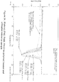
FIG. 17 is an example DSC trace of FARSOON PA3 nylon material, before and after treating according to the illustrative embodiments. -
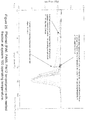
FIG. 18 is an example DSC trace of anylon 46 material, before and after treatment according to the illustrative embodiments. -
FIG. 19 is an example DSC trace of a Nyloteknylon 6 material, before and after treatment according to the illustrative embodiments. -
FIG. 20 is an example DSC trace of anylon 6 material, Arkema Orgasol ES 1002, before and after treatment according to the illustrative embodiments. -
FIG. 21 is an example DSC trace of a Polypropylene material, Polypropylene A, before and after treatment according to the illustrative embodiments. -
FIG. 22 is an example DSC trace of a Polypropylene material, Polypropylene B, before and after treatment according to the illustrative embodiments. -
FIG. 23 is an example DSC trace of a polyethylene material, Petrothene PE HDBM, before and after treatment according to the illustrative embodiments. -
FIG. 24 is an example DSC trace of a polyamide ter-polymer, Platimid M1757 (Polyamide 6, Polyamide 66, Polyamide 12), before and after treatment according to the illustrated embodiments. -
FIG. 25 is an example DSC trace of Platimid M1757 with melted fraction atsystem 100 operating temperature. -
FIG. 1 is a perspective schematic view of an SLS system, indicated generally at 100, of the illustrative embodiment.FIG. 2 is a perspective schematic cutaway view of thesystem 100. Thesystem 100 forms objects by processing powder materials. As shown inFIG. 1 , thesystem 100 includes at least apart bed 102, an energy-directing mechanism 104 (e.g., a C02 laser) for directing energy onto atop surface 106 of thepart bed 102, a feed mechanism 108 (e.g., a roller, blade or other spreader) for distributing smooth layers of unfused powder from acartridge 110 onto thepart bed 102, and acomputer 112 for automatically controlling operation of thesystem 100. For clarity,FIG. 1 does not show various connections between thecomputer 112 and other components of thesystem 100. In turn, thecomputer 112 operates in response to instructions from a human user (not shown inFIG. 1 ). - In the illustrative embodiment, the
part bed 102 is located within an oxygen-controlled cabinet or chamber, and thesystem 100 maintains a suitable temperature for powder on the part bed 102 (e. g., with a heater). Within a first layer of powder on thetop surface 106, in response to signals from the computer 112: (a) the energy-directing mechanism 104 directs energy to hitpowder 202 within across-sectional region 204 as shown inFIG. 2 ; (b) such directed energy elevates a temperature of thecross-sectional region 204 enough to soften and fuse together thepowder 202 within thecross-sectional region 204, so that it becomes fused powder 206 as shown inFIG. 2 ; and (c) in the same manner, thesystem 100 is operable to selectively fuse powder within one or more other cross-sectional regions to form a first layer of an object, which is specified by thecomputer 112. In one example, such fusion is achieved by softening outside surfaces of the powder's particles (e. g., by partially melting them), so that they fuse (or "stick") to one another, irrespective of whether they completely melt. - After the
system 100 forms the first layer of the object, the system 100: (a) lowers thepart bed 102 by a specified layer thickness; (b) raises thecartridge 110 of feed powder by a further specified layer thickness; (c) with thefeed mechanism 108, smoothly distributes (e.g., spreads) a second layer of powder from thecartridge 110 onto the first layer of powder; and (d) selectively fuses powder within one or more cross-sectional regions to form a second layer of the object (within the second layer of powder) and to fuse the second layer of the object to the first layer of the object. In the same manner, thesystem 100 repeats such process to form successive layers of the object (within successive layers of powder), until the object's entire shape is formed. Accordingly, thesystem 100 performs laser sintering as an additive layer digital manufacturing technique, in which thesystem 100 repeatedly: (a) over a horizontal plane, spreads layers of powder, which collectively form a bed ofpowder 208 as shown inFIG. 2 ; and (b) uses the energy-directing mechanism 104 (e. g., an infrared laser beam or electron beam) to selectively use (e. g., sinter) cross-sectional regions within those layers. - The object (or "part") is a three dimensional solid object, and the layers are relatively thin (e. g., typically less than 0.010 inches per layer). During the object's formation, the remaining unfused (e.g., unsintered) powder, which is excluded from the object, remains in place to physically support the various layers of powder. After the object's entire shape is formed, the remaining unfused powder is separated from the object. Accordingly, the remaining unfused powder is soft enough to recover the sintered object from the powder. In one example, the remaining unfused powder is processed (e. g., partially reused, and/or blended with fresh powder) for making another object.
- Preferably, the object is useful, has a desired size and shape, and has other properties (e.g., strength, ductility, hardness and conductance) for achieving the object's intended purpose. To make either prototype or functional objects, successful use of the
system 100 partly depends on the powder's melting behavior. For example, the object's properties are influenced by the powder's base materials, ingredients blended with those base materials, and operating conditions of thesystem 100. - During the object's formation, the
system 100 maintains a specified temperature for the bed ofpowder 208, so that the fused powder 206 remains partially molten as more layers are added to the bed ofpowder 208 and selectively melted. For example, if thesystem 100 maintains a temperature that is too low for the bed of powder 208 (e.g., too near such powder's recrystallization point), then the fused powder 206 may return to a solid state (or "recrystallize") too quickly, which may cause the formed object to warp or deform. However, if thesystem 100 maintains a temperature that is too high for the bed of powder 208 (e.g., too near such powder's melting point), then the remaining unfused powder may partially melt, which may increase the relative difficulty of separating the remaining unfused powder from the formed object. - Preferably, for SLS processing, the powder has a relatively large positive difference between a temperature at which the powder melts ("Tm") and a temperature at which the powder recrystallizes ("Trc"). For example, during the object's formation, if the bed of
powder 208 has a relatively large positive difference between Tm and Trc (ΔT = Tm - Trc), then thesystem 100 is more easily operable to maintain a suitable temperature that: (a) keeps the fused powder 206 partially molten, so that the formed object is less likely to warp or deform; and (b) simultaneously, avoids partial melt of the remaining unfused powder, so that the remaining unfused powder is more easily separable from the formed object. -
FIG. 3 is a first example DSC trace of a first powder, showing a melting curve and a recrystallization curve for the first powder. On the melting curve inFIG. 3 , a point A marks a temperature at which onset of melting occurs for the first powder ("melting onset" or "Tmo"), and a point B marks a temperature at which melting energy peaks for the first powder ("melting pea " or "Tm"). On the recrystallization curve inFIG. 3 , a point C marks a temperature at which onset of recrystallization occurs for the first powder ("recrystallization onset" or "Tro"), and a point D marks a temperature at which recrystallization energy peaks for the first powder ("recrystallization peak" or "Trc"). If the first powder has a relatively large positive difference between the point A and the point C, and a relatively large positive difference between the point B and the point D, then the first powder is relatively well-suited for use in thesystem 100. -
FIG. 4 is a second example DSC trace of a second powder, showing a melting curve and a recrystallization curve for the second powder. On the melting curve inFIG. 4 , a point A marks the melting onset Tmo for the second powder, and a point B marks the melting peak Tm for the second powder. On the recrystallization curve inFIG. 4 , a point C marks the recrystallization onset Tro for the second powder, and a point D marks the recrystallization peak Trc for the second powder. - The second powder includes multiple crystalline morphologies which tend to melt and recrystallize at temperatures that vary from one another on a material-by-material basis. In the example of
FIG. 4 , such variation causes a negative difference between the point A and the point C. Accordingly,FIG. 4 shows anarea 1, which is a range of temperatures at which the second powder's melting overlaps with the second powder's recrystallization. Similarly,FIG. 4 shows anarea 2, which is a range of temperatures at which the second powder's recrystallization overlaps with the second powder's melting. Often, such negative difference between the point A and the point C would make the second powder relatively unsuitable for use in thesystem 100. Nevertheless, if thearea 1 and thearea 2 are relatively small, then the second powder is potentially suitable for use in thesystem 100. - In some cases, a commercial sintering material has: (a) a first Tm ("Tm1") when the material is melted a first time; and (b) a second Tm ("Tm2"), which is lower than Tm1, when the material is melted a second (or subsequent) time. The
system 100 is operable to heat such material at a temperature below Tm1, yet near Tm2, so that the formed object remains in a molten (or partially molten) state without melting the remaining unfused powder, because the formed object has already been melted a first time by the energy-directingmechanism 104. - At least one relatively good commercial sintering powder includes material that melts at a lower temperature than the bulk of such powder. If a powder includes material that melts at a lower temperature than the bulk of such powder, then: (a) such lower temperature is referenced as a melting onset ("Tmo"); and (b) if the difference between Trc and Tmo is too small, then such powder is relatively unsuitable for use in the
system 100. - Preferably, a commercial sintering powder has: (a) a relatively large positive difference between its Tm and Trc; (b) a Tm2 that is lower than its Tm1; and (c) a relatively small difference between its Tmo and Tm, so that none of the powder melts prematurely (which would cause the remaining unfused powder to also partially melt and fuse together).
- For SLS processing,
EOS PA 2201 is a suitable dual melt point material. The material is available from EOS Gmbh of Germany. Also, 3D SYSTEMS, Inc, a US Corporation, supplies the material under the product name "DURAFORM PA". The material has at least two crystalline states. For example, if such material has not been previously melted, then a DSC of such material shows that: (a) its melt temperature ("first melting peak" or "Tm1") is normally ∼186°C; and (b) upon cooling, it recrystallizes at ∼145°C. By comparison, if such material has been previously melted, then a DSC of such material shows that its melt temperature ("second melting peak" or "Tm2") has dropped to ∼178°C and its second melt peak onset temperature ("Tmo (2)" has dropped to ∼172°C. - Examples of conventional SLS materials and their melting behaviors are shown in the following table:
Material First Melting Peak ("Tm1") Second Melting Peak ("Tm2") Recrystallization Peak ("Trc") Melting Onset ("Tmo") Recrystallization Onset ("Tro") DURAFORM PA or EOS PA2200/2201 186°C 178°C 148°C 180 °C 153 ° C ARKEMA ORGASOL 2003 182°C 178°C 149°C 172 °C 153 °C ARKEMA RILSAN D80 186°C 188°C 163°C 182 °C 166 °C - As can be seen from the table and confirmed by processing in the
system 100, the Duraform PA, PA2200/PA2201 material is easier to successfully produce parts with.The Arkema Rilsan D80 is a relatively difficult material to process using thesystem 100. The temperature measurements presented in the table above were produced according to ASTM D3418-03 (Standard Test Method for Transition Temperatures and Enthalpies of Fusion and Crystallization of Polymers by Differential Scanning Calorimetry) with a TA Instruments TA Q10 DSC tool. For the evaluation of the Tm, the Trc, the onset points and the melt enthalpy (ΔHm), standard aluminum pans were used and the heating and cooling was performed as follows: (1) equilibrating at 40 °C, (2) ramping at 10 °C/min to 215 °C, (3) holding isothermal for 5 minutes, (4) ramping at -10 °C/min to 50 °C, (5) holding isothermal for 1 minute, and then (6) ramping at 10 °C/min to 250 °C. - Semi-crystalline materials (e.g., polymers) may have various crystalline states that coexist with one another. The
system 500 treats (e.g., by heating or annealing) polymers that form the powders or the powders themselves.FIG 5-1 . is a perspective view of an example of such a treatment system. Such treatment occurs at particular temperatures, pressures and durations. Such treatment modifies crystalline states for such polymers, which in turn improves their relative suitability for use in the system 100 (e.g., increases their temperature range of processibility for SLS). In one example, such treatment changes a ratio of various crystalline states for such polymers, resulting in observable changes in melting and recrystallization temperatures for such polymers. - In the
system 500, a material source (501) is supplied. The material in inputted into avessel 503 through amaterial transfer system 502 of the vessel, for example a pump, conveyor, or similar such device. The material enters thevessel 503 through aninlet 510. A heat transfer device (505) is then used to apply heat produced from aheat source 504 to the material in the vessel. Examples of such a heat source include, but are not limited to, heated oil and/or electrical heaters. Examples of a heat transfer device include, but are not limited to, an optional jacket around the vessel used to circulate a heated fluid (eg such as a gas or an oil) on the outside of the vessel and/or using heating elements, such as electrical heating elements, applied directly to the outside surface of the vessel. In one embodiment, thesystem 500 treats the material supplied frommaterial source 501 at temperatures near such polymer's Tmo. At such temperatures, thesystem 500 may also keep such material in a fluidized state (e.g., agitated or stirred) using an agitator or stirringdevice 506, so that such material substantially avoids caking or sticking together if the material is a powder or similarly small grain sized material. Such agitation can take many forms, examples include, but are not limited to, fluidizing through pressurized gas flow from thegas source 508 or using a mechanical stirring or agitation device such as a mixer blade powered bypower source 507. Also, such fluidization generally promotes a more uniform temperature distribution throughout a mass of such material being treated resulting in a more consistent final material output from thesystem 500. One embodiment of thesystem 500 may also provide for a gas inlet (509) into the vessel to provide from thegas source 508 either an inerting gas to prevent oxidation of the material and/or provide pressure in the vessel for the treatment. Thesystem 500 also provides for a means of removing the treatedmaterial 513 from thevessel 503 through anoutlet 511 and additionalmaterial transfer device 502. Optionally this material may be transferred to amaterial storage device 514, for example another vessel. The treatment process may be sufficiently automated and controlled through an attached control orcomputer device 512 managing any one or all of the following of time, temperature, pressure, agitation, gas flow, heat, and or material flow in or out of the treatment vessel. - Multiple embodiments of the
system 500 and its use to produce relatively more suitable materials for use in thesystem 100 are possible. Thesystem 500 may be configured to treat materials in multiple forms, such as pellets, flakes, and or powders of varying sizes. The treatment process may also be applied to the material in different stages of the process of preparing a powdered material for use in thesystem 100. -
Figure 5-2 shows an example of a process flowchart of using thesystem 500 in the preparation of a powder suitable for use by thesystem 100. In this process, araw material 601 is provided. This raw material may be pellets, flakes, and or a powder of varying size. It may be advantageous to mixvarious additives 602 into theraw material 601 prior to treatment by commonly known practices of compounding or melt-mixing and extruding theraw materials 601 andadditives 602 using a compounder and extruder other similarsuch device 603. This output compoundedmaterial 604 may be advantageous in thesystem 100 or similar such additive manufacturing processes utilizing powders in that the material, when transformed into a usable powder form byprocess system 100. - The output compounded
material 604 may be powderised by apowderization device 605 before or after treatment by thesystem 500. Examples of such apowderization device 605 include, but are not limited to, such commonly practiced techniques as grinding or milling. Such processes typically produce particles of irregular sizes and shapes that may optionally be rounded instep 606 through any number of commonly available particle rounding processes and/or sorted by particle size by common and well known methods such as mechanical sieving or air classification instep 607.Additional additives 609 orraw materials 610 in powder form or other form may be added by blending or other dry mixing methods instep 608 and at any point processes 605, 606, and/or 607 may be repeated either singly or in any combination. At any point, the powderized, shaped, sorted, and/or additionally mixed or blended may material may be sent for treatment to thesystem 500 for treatment. Theoutput material 513 of thesystem 500 may be subjected to multiple repetitive treatments by thesystem 500, sent for powderisation or further compounding with additional additives or raw materials and or output for use by thesystem 100. - A further embodiment of the use of the
system 500 is presented inFigure 5-3 . In this embodiment, thevessel 503 ofFigure 5-1 has been modified to apipe 701. This pipe contains amaterial transfer mechanism 702, such as an auger or conveyor, that gradually moves powder down the length of the pipe. In this manner, the material stays in thepipe 701 for a length of treatment time governed by the speed of the transfer mechanism and the length of the pipe. Thepipe 701 is heated as in thesystem 500 using aheat transfer mechanism 703 and aheat source 704. Power for the material transfer mechanism is provided via apower source 705 and provisions are made for material transfer devices into and out of the pipe. As inFigure 5-1 , thepipe vessel 701 may be supplied with gas from a gas source and the entire system controlled by acomputer 512. - In another application of the
system 500, the treatedoutput material 513 is transferred into astorage vessel 800 shown inFigure 5-4 using amaterial transfer device 502 through aninlet 810 intovessel 800. The storage vessel may be heavily insulated in order to maintain the treated output material at a relatively high temperature for long periods of time. The material may occasionally be transferred using a secondmaterial transfer device 502 through an outlet (811) in thevessel 800 into thesystem 500'sheating vessel 503 to be reheated to a desired temperature. As inFigure 5-1 , thestorage vessel 800 may be provided with a gas source (808) and a gas inlet (809) in order to maintain an inert atmosphere inside thevessel 800. The output from thesystem 800 vessel may at any time be transferred to further processes for powderization, sizing, shaping, additional mixing or blending of further raw materials or additives, and/or packaged for use in thesystem 100. The entire process may be optionally controlled by acomputer 512. - In the manners above, the
system 500 improves the powder's melting and recrystallization temperatures by any combination of one or more of the following: (a) increasing a difference between the powder's Tm and Trc by increasing the powder's Tm; (b) increasing a difference between the powder's Tm and Trc by reducing the powder's Trc; (c) increasing a difference between the powder's Tm1 and Tm2; (d) increasing a difference between the powder's Tm1 and Trc; (e) increasing the powder's Tmo; and (f) reducing the powder's Tro. Accordingly, the illustrative embodiments: (a) make some powders more suitable for SLS processing (e.g., easier to process by SLS), even if such powders are already relatively suitable for SLS processing; and (b) make some powders relatively suitable for SLS processing, even if such powders are not already relatively suitable for SLS processing. - As a first example, in a closed vessel under nitrogen atmosphere, the
system 500 pretreated a sample of ARKEMA ORGASOL lot 265 ("ORGASOL 2003 Sample") material, which isARKEMA ORGASOL 2003 material.ARKEMA ORGASOL 2003 material is a nylon-12 powder available from ARKEMA Corporation of France. For SLS processing,ARKEMA ORGASOL 2003 material is relatively difficult to use, especially when compared to more commonly used material (e.g.,EOS PA 2201, EOS PA 2200, 3D SYSTEMS Duraform PA). A large percentage of commercially available SLS powders include theEOS PA 2201, EOS PA 2200, and 3D SYSTEMS Duraform PA materials as a base polymer component. -
FIG. 6 is an example DSC trace of a sample of EOS PA2201 lot 919577 ("EOS PA2201 Sample") material.FIG. 6 is an example DSC trace of theORGASOL 2003 Sample material. As shown inFigs. 5 and6 , the EOS PA2201 Sample material has a melting peak Tm1 (FIG. 5 ) that is several degrees higher than a melting peak Tm1 (FIG. 7 ) of thecompetitive ORGASOL 2003 Sample material. The temperature measurements presented above were produced according to ASTM D3418-03 (Standard Test Method for Transition Temperatures and Enthalpies of Fusion and Crystallization of Polymers by Differential Scanning Calorimetry) with a TA Instruments TA Q10 DSC tool. For the evaluation of the Tm, the Trc, the onset points and the melt enthalpy (ΔHm), standard aluminum pans were used and the heating and cooling was performed as follows: (1) equilibrating at 50 °C, (2) ramping at 10 °C/min to 215 °C, (3) holding isothermal for 5 minutes, (4) ramping at -10 °C/min to 50 °C, (5) holding isothermal for 1 minute, and then (6) ramping at 10 °C/min to 250 °C -
FIG. 8 is an example DSC trace of theORGASOL 2003 Sample material, after such material was pretreated with heat ("heat treated") for durations varying between 18 hours and 88 hours by thesystem 500 at 166°C-168°C in a closed vessel under nitrogen atmosphere. Such pretreatment improved theORGASOL 2003 Sample material's temperature range of processibility for SLS, as shown inFIG. 7 and the following table. The temperature measurements presented above were produced according to ASTM D3418-03 (Standard Test Method for Transition Temperatures and Enthalpies of Fusion and Crystallization of Polymers by Differential Scanning Calorimetry) with a TA Instruments TA Q10 DSC tool. For the evaluation of the Tm, the Trc, the onset points and the melt enthalpy (ΔHm), standard aluminum pans were used and the heating and cooling was performed as follows: (1) equilibrating at 50 °C, (2) ramping at 10 °C/min to 215 °C, (3) holding isothermal for 5 minutes, (4) ramping at -10 °C/min to 50 °C, (5) holding isothermal for 1 minute, and then (6) ramping at 10 °C/min to 250 °CSample Melting Peak ("Tm1") Melting Onset ("Tmo") Recryslallization Peak ("Trc") Recrystallisation Onset ("Tro") EOS PA2201 Lot 919577 186.27°C 180.46°C 148.06°C 153.7,5° C ARKEMA ORGASOL 2003 control sample (non-pretreated) 181.66°C 175.14°C 149.78°C 152.74° C ARKEMA ORGASOL 2003 pretreated sample (heat treated 88 hours at 166°C-168°C) 184.39°C 180.29°C 152.03°C 154.55°C - As shown in
FIG. 8 and the table above, such pretreatment of theORGASOL 2003 Sample material causes its melting behavior to approach the EOS PA2201 Sample material's melting behavior, so that such pretreatedORGASOL 2003 Sample material is more suitable for SLS processing.FIG. 9 is an example DSC trace of theORGASOL 2003 Sample material, the pretreatedORGASOL 2003 Sample material, and the EOS PA2201 Sample material, in comparison to one another. As shown inFIG. 9 , the pretreatedORGASOL 2003 Sample material's first melting peak Tm1 is 184.39°C, which is substantially higher than thenon-pretreated ORGASOL 2003 Sample material's first melting peak Tm1 of 181.66°C. The temperature measurements presented above were produced according to ASTM D3418-03 (Standard Test Method for Transition Temperatures and Enthalpies of Fusion and Crystallization of Polymers by Differential Scanning Calorimetry) with a TA Instruments TA Q10 DSC tool. For the evaluation of the Tm, the Trc, the onset points and the melt enthalpy (ΔHm), standard aluminum pans were used and the heating and cooling was performed as follows: (1) equilibrating at 50 °C, (2) ramping at 10 °C/min to 215 °C, (3) holding isothermal for 5 minutes, (4) ramping at -10 °C/min to 50 °C, (5) holding isothermal for 1 minute, and then (6) ramping at 10 °C/min to 250 °C - Furthermore, in comparison to the EOS PA2201 Sample material, such pretreated
ORGASOL 2003 Sample material appears to have an additional advantage in the shape of its melting curve. For example, during formation of an object with the EOS PA2201 Sample material, thesystem 100 maintains a temperature of ∼178°C for the bed ofpowder 208. As shown inFIG. 9 , a percentage of the EOS PA2201 Sample material that melted at 178°C is represented by a shaded area within such material's melting curve for temperatures ranging up to 178°C. Such area indicates that, in comparison to the pretreatedORGASOL 2003 Sample material: (a) a higher percentage of the EOS PA2201 Sample material is molten at 178°C; and (b) accordingly, after the object's entire shape is formed by thesystem 100 with the EOS PA2201 Sample material, the remaining unfused EOS PA2201 Sample material's powder would be relatively more difficult to separate from the object. As can also be seen by theFIG. 9 , a substantially smaller percentage of the treatedORGASOL 2003 material is melted at the temperature of ∼178°C than for theun-treated ORGASOL 2003 material providing a substantially improved ability to remove unfused material from objects produced by thesystem 100. -
FIG. 10 is an example DSC trace of theORGASOL 2003 Sample material, after such material was heat treated for 88 hours by thesystem 500. Such treatedORGASOL 2003 Sample material's second melting curve inFIG. 10 is substantially unchanged in comparison to the example DSC trace of thenon-pretreated ORGASOL 2003 Sample material inFIG. 7 . Furthermore, its recrystallization temperature is also substantially unchanged. However, said sample material's first melting curve is substantially changed by the treatment method of thesystem 500 including substantially increased first melting peak temperatures and first melting onset temperatures. In a test of suitability for SLS processing, a DTM 2500 PLUS laser sintering machine version of thesystem 100 formed: (a) a first object with a batch of theORGASOL 2003 material treated by thesystem 500; (b) a second object with a batch of thenon-pretreated ORGASOL 2003 Sample material. Such batches were relatively small, and such objects included warpage bars (which were formed at a length of 12 inches on the front of each object). The remaining unfused powder (e.g., within the bed ofpowder 208 on the part bed 102) that existed during formation of the first object: (a) was substantially softer (e.g., less caking) than the remaining unfused powder that existed during formation of the second object; and (b) in terms of softness, was approximately the same as the remaining unfused powder that existed during formation of the third object. Moreover, the first object's warpage bars showed substantially less warpage than the second object's warpage bars, which is a factor to be considered in commercial use of such materials. The temperature measurements presented above were produced according to ASTM D3418-03 (Standard Test Method for Transition Temperatures and Enthalpies of Fusion and Crystallization of Polymers by Differential Scanning Calorimetry) with a TA Instruments TA Q10 DSC tool. For the evaluation of the Tm, the Trc, the onset points and the melt enthalpy (ΔHm), standard aluminum pans were used and the heating and cooling was performed as follows: (1) equilibrating at 50 °C, (2) ramping at 10 °C/min to 215 °C, (3) holding isothermal for 5 minutes, (4) ramping at -10 °C/min to 50 °C, (5) holding isothermal for 1 minute, and then (6) ramping at 10 °C/min to 250 °C -
FIG. 11 is an example DSC trace of the pretreatedORGASOL 2003 Sample material ofFIG. 10 , after such material was heat treated for an additional 87 hours by thesystem 100 at 167°C-168°C in a closed vessel under nitrogen atmosphere, so that such material was heat treated for a total of 175 hours (i.e., 88 hours in the example ofFIG. 10 , plus the additional 87 hours in the example ofFIG. 11 ). As shown inFIG. 11 , such pretreatment caused: (a) an increase to 185.23°C in such material's first melting peak Tm1; and (b) a relatively large increase to 183.77°C in such material's melting onset Tmo. The temperature measurements presented above were produced according to ASTM D3418-03 (Standard Test Method for Transition Temperatures and Enthalpies of Fusion and Crystallization of Polymers by Differential Scanning Calorimetry) with a TA Instruments TA Q10 DSC tool. For the evaluation of the Tm, the Trc, the onset points and the melt enthalpy (DHm), standard aluminum pans were used and the heating and cooling was performed as follows: (1) equilibrating at 50 °C, (2) ramping at 10 °C/min to 215 °C, (3) holding isothermal for 5 minutes, (4) ramping at -10 °C/min to 50 °C, (5) holding isothermal for 1 minute, and then (6) ramping at 10 °C/min to 250 °C -
FIG. 12 is an example DSC trace of theORGASOL 2003Lot 059 Sample material, after such material was heat treated for 60 hours by thesystem 500 at 171°C in a closed vessel under nitrogen atmosphere at a pressure of 3,000 psi, which is substantially higher than atmospheric pressure at sea level (e.g., 3,000 psi is more than two orders of magnitude higher than atmospheric pressure at sea level).FIG 12 shows a DSC plot of treated material compared to two reference runs of un-treated material. As shown inFIG. 12 , such treatment caused: (a) an increase of approximately 1°C in such material's first melting peak Tm1; and (b) an increase of approximately 15°C in such material's melting onset Tmo. The temperature measurements presented above were produced according to ASTM D3418-03 (Standard Test Method for Transition Temperatures and Enthalpies of Fusion and Crystallization of Polymers by Differential Scanning Calorimetry) with a TA Instruments TA Q10 DSC tool. For the evaluation of the Tm, the Trc, the onset points and the melt enthalpy (ΔHm), standard aluminum pans were used and the heating and cooling was performed as follows: (1) equilibrating at 50 °C, (2) ramping at 10 °C/min to 215 °C, (3) holding isothermal for 5 minutes, (4) ramping at -10 °C/min to 50 °C, (5) holding isothermal for 1 minute, and then (6) ramping at 10 °C/min to 250 °C -
FIG. 13 is a first example DSC trace of a sample ofARKEMA ORGASOL lot 059 material (which isARKEMA ORGASOL 2003 material), after such material was heat treated by thesystem 500 in a closed vessel under nitrogen atmosphere in three stages, namely: (a) a first stage in which such material was annealed for 24 hours by thesystem 500 at 171°C; (b) a second stage in which such material was annealed for an additional 24 hours by thesystem 500 at 175°C; and (c) a third stage in which such material was annealed for yet another 24 hours by thesystem 500 at 177°C. The temperature measurements presented above were produced according to ASTM D3418-03 (Standard Test Method for Transition Temperatures and Enthalpies of Fusion and Crystallization of Polymers by Differential Scanning Calorimetry) with a TA Instruments TA Q10 DSC tool. For the evaluation of the Tm, the Trc, the onset points and the melt enthalpy (ΔHm), standard aluminum pans were used and the heating and cooling was performed as follows: (1) equilibrating at 50 °C, (2) ramping at 10 °C/min to 215 °C, (3) holding isothermal for 5 minutes, (4) ramping at -10 °C/min to 50 °C, (5) holding isothermal for 1 minute, and then (6) ramping at 10 °C/min to 250 °C - In heat treating a powdered material, the
system 500 gradually increases such material's temperature as it approaches such material's melting onset Tmo. In that manner, such material is: (a) less likely to agglomerate during the heat treating; and (b) more likely to flow within the heat treating vessel. By maintaining relatively good physical flow properties within the heat treating vessel, such powdered material is more easily: (a) removed from the heat treating vessel, so that such material is more readily available for subsequent SLS processing by thesystem 100; and (b) stirred within the heat treating vessel, so that a more uniform temperature distribution is generally promoted throughout a mass of such material. - As shown in the following table, a representative material's melting peak Tm1 and its melting onset Tmo increase correspondingly with each 24-hour heat treatment.
Time and temperature Melting Peak ("Tm1") Melting Onset ("Tmo") Control Sample, non-pretreated 181.33°C 173.45°C Heat treated, 24 hours at 171°C 182.04°C 175-71°C Heat treated, additional 24 hours at 175°C (total 48 hours) 182.42°C 178.35°C Heat treated, yet another 24 hours at 177°C (total 72 hours) 182.87°C 179.91°C. -
FIG. 14 is an example DSC trace of a sample of ARKEMA ORGASOL lot 2110355 ("ORGASOL 2002 Sample") material, which isARKEMA ORGASOL 2002 material.ARKEMA ORGASOL 2002 material is a coating nylon-12 powder available from ARKEMA Corporation of France. As shown inFIG. 14 , such material's first and second melting peaks Tm1 and Tm2 are effectively the same. Accordingly, such material has a relatively small temperature range of processibility for SLS by thesystem 100. Nevertheless, such material has been available in relatively large volumes at relatively low cost, especially in comparison toARKEMA ORGASOL 2003 material and other specialty materials. The temperature measurements presented above were produced according to ASTM D3418-03 (Standard Test Method for Transition Temperatures and Enthalpies of Fusion and Crystallization of Polymers by Differential Scanning Calorimetry) with a TA Instruments TA Q10 DSC tool. For the evaluation of the Tm, the Trc, the onset points and the melt enthalpy (ΔHm), standard aluminum pans were used and the heating and cooling was performed as follows: (1) equilibrating at 50 °C, (2) ramping at 10 °C/min to 215 °C, (3) holding isothermal for 5 minutes, (4) ramping at -10 °C/min to 50 °C, (5) holding isothermal for 1 minute, and then (6) ramping at 10 °C/min to 250 °C -
FIG. 15 is an example DSC trace of theORGASOL 2002 Sample material, after such material was heat treated for durations varying between 18 hours and 88 hours by thesystem 500 at 166°C-168°C in a closed vessel under nitrogen atmosphere. Such pretreatment improved theORGASOL 2002 Sample material's temperature range of processibility for SLS, as shown inFIG. 15 and the following table. The temperature measurements presented above were produced according to ASTM D3418-03 (Standard Test Method for Transition Temperatures and Enthalpies of Fusion and Crystallization of Polymers by Differential Scanning Calorimetry) with a TA Instruments TA Q10 DSC tool. For the evaluation of the Tm, the Trc, the onset points and the melt enthalpy (ΔHm), standard aluminum pans were used and the heating and cooling was performed as follows: (1) equilibrating at 50 °C, (2) ramping at 10 °C/min to 215 °C, (3) holding isothermal for 5 minutes, (4) ramping at -10 °C/min to 50 °C, (5) holding isothermal for 1 minute, and then (6) ramping at 10 °C/min to 250 °CSample Melting Peak ("Tm1") Melting Onset ("Tmo") Recrystallization Peak ("Trc") Recrystallization Onset ("Tro") ORGASOL 2002 - Control Sample, non-pretreated 177.82°C 173.64°C 150.58°C 153.34° C ORGASOL 2002, heat treated 18 hours at 166°C-168°C 180.00°0C 175.19°C 151.02°C 153.65° C ORGASOL 2002. heat treated 46 hours at 160°C-168°C 180.73°C 177.33°C 150.95°C 153.57° C ORGASOL 2002. heat treated 88 hours at 166°C-168°C 180.05°C & 183.53°C 178.67°C 150.56°C 153.45°C -
FIG. 16 is an example DSC trace of theORGASOL 2002 Sample material, after such material was heat treated for 88 hours by thesystem 500 at 167°C-168°C in a closed vessel under nitrogen atmosphere. As shown inFIG. 16 , such pretreatment caused: (a) an increase in such material's first melting peak Tm1; and (b) a relatively large increase in a difference between such material's first melting peak Tm1 and its second melting peak Tm2. Further, as shown inFIG. 16 , such material's first melting peak Tm1 includes two peaks, namely: (a) a first peak at ∼180 °C; and (b) a second higher peak at 183.53°C. To at least some extent, the application of more treatment time by thesystem 500 would continue to gradually move the lower peak towards the higher peak and the higher peak to a greater temperature overall peak. The temperature measurements presented above were produced according to ASTM D3418-03 (Standard Test Method for Transition Temperatures and Enthalpies of Fusion and Crystallization of Polymers by Differential Scanning Calorimetry) with a TA Instruments TA Q10 DSC tool. For the evaluation of the Tm, the Trc, the onset points and the melt enthalpy (ΔHm), standard aluminum pans were used and the heating and cooling was performed as follows: (1) equilibrating at 50 °C, (2) ramping at 10 °C/min to 215 °C, (3) holding isothermal for 5 minutes, (4) ramping at -10 °C/min to 50 °C, (5) holding isothermal for 1 minute, and then (6) ramping at 10 °C/min to 250 °C -
FIG. 17 is an example DSC trace of FARSOON PA3 material, which is a nylon powder available from HUNAN FARSOON COMPANY of China. Such material was heat treated by thesystem 500 at 171°C in a closed vessel under nitrogen atmosphere in two cases, namely: (a) a first case in which a first sample of such material was heat treated for 24 hours by thesystem 100; and (b) a second case in which a second sample of such material was heat treated for 72 hours by thesystem 500. Such pretreatment improved the FARSOON PA3 material's temperature range of processibility for SLS, as shown inFIG. 17 and the following table. The temperature measurements presented above were produced according to ASTM D3418-03 (Standard Test Method for Transition Temperatures and Enthalpies of Fusion and Crystallization of Polymers by Differential Scanning Calorimetry) with a TA Instruments TA Q10 DSC tool. For the evaluation of the Tm, the Trc, the onset points and the melt enthalpy (ΔHm), standard aluminum pans were used and the heating and cooling was performed as follows: (1) equilibrating at 50 °C, (2) ramping at 10 °C/min to 230 °C, (3) holding isothermal for 5 minutes, (4) ramping at -10 °C/min to 50 °C, (5) holding isothermal for 1 minute, and then (6) ramping at 10 °C/min to 230 °CSample Melting Peak ("Tm1") Melting Onset ("Tmo") Recryslallization Peak ("Trc") Recrystallization Onset ("Tro") FARSOON PA3 188.26°C 180.82°C 154.38°C 159.31°C FARSOON PA3, heat treated 24 hours at 171°C 190.87°C 182.70°C 143.69°C 151.37°C FARSOON PA3, heat treated 72 hours at 171°C 191.82°C 184.48°C 142.28°C 150.02°C - Some laser sintering machines have relatively precise requirements for powdered material that is processed by such machines. For example, some laser sintering machines are sensitive to relatively small variations in such material's melting behavior (and/or relatively small variations in temperature). By suitably heat treating such material before SLS processing with the
system 500, the illustrative embodiments are operable to: (a) correct batch-to-batch variations in such material from suppliers; and (b) in that manner, improve consistency of such material's melting behavior for achieving higher quality control and repeatability in SLS processing with thesystem 500. - In a further embodiment, a nylon-46 material (PA46 supplied by DSM) was treated by the
system 500. PA46 is particularly useful for sintering due to its substantially higher melting point compared to other nylons, thus, allowing thesystem 100 to make parts that can be used in higher temperature operating environments.FIG. 18 shows an example DSC trace of the PA46 material before and after treatment. In this example, the PA46 was treated for 15 hours by thesystem 500 at 280°C in a closed vessel under a nitrogen atmosphere. As can be seen fromFIG. 18 , the treatment had a substantial impact on the first melting point of the material, increasing the first melting peak from 288.78 °C to 319.29 °C, an increase of over 30 °C. Furthermore, the first melt onset increased even more, from 280.27 °C to 313.42 °C, an increase of over 33 °C. The recrystallization temperature also decreased, increasing the difference between the melting peak and the recrystallization peak. InFIG 18 . the recrystallization temperature decreased from 254.98 0C to 246.69 °C, further improving the processing window of the material in thesystem 100. The treatment by thesystem 500 shows a substantial increase in the processability of the material by thesystem 100. The temperature measurements presented above were produced according to ASTM D3418-03 (Standard Test Method for Transition Temperatures and Enthalpies of Fusion and Crystallization of Polymers by Differential Scanning Calorimetry) with a TA Instruments TA Q10 DSC tool. For the evaluation of the Tm, the Trc, the onset points and the melt enthalpy (ΔHm), standard aluminum pans were used and the heating and cooling was performed as follows: (1) equilibrating at 50 °C, (2) ramping at 20 °C/min to 350 °C, (3) holding isothermal for 5 minutes, (4) ramping at -20 °C/min to 50 °C, (5) holding isothermal for 1 minute, and then (6) ramping at 20 °C/min to 350 °. - In a further embodiment, a nylon-6 material (supplied by Nylotek) was treated by the
system 500.FIG. 19 shows an example DSC trace of the PA6 material before and after treatment. In this example, the PA66 was treated for 24 hours by thesystem 500 at 212°C in a closed vessel under a nitrogen atmosphere. As can be seen from theFIG. 19 , the treatment by thesystem 500 substantially narrowed the first melting curve of the material. In this example, the melting onset temperature shifted from 209.3 °C to 217.08 °C. This substantially increased melting onset temperature improves the ease of use of the material in thesystem 100. The temperature measurements presented above were produced according to ASTM D3418-03 (Standard Test Method for Transition Temperatures and Enthalpies of Fusion and Crystallization of Polymers by Differential Scanning Calorimetry) with a TA Instruments TA Q10 DSC tool. For the evaluation of the Tm, the Trc, the onset points and the melt enthalpy (ΔHm), standard aluminum pans were used and the heating and cooling was performed as follows: (1) equilibrating at 50 °C, (2) ramping at 10 °C/min to 250 °C, (3) holding isothermal for 5 minutes, (4) ramping at -10 °C/min to 50 °C, (5) holding isothermal for 1 minute, and then (6) ramping at 10 °C/min to 250 °. - A further nylon-6 material sample was tested using the treatment method of the
system 500. This nylon-6 material was produced by Arkema corporation as ES 1002. A sample of this material was treated by thesystem 500 for a period of 24 hours at 200°C under nitrogen.FIG. 20 shows a DSC trace of the untreated and treated material. As can be seen fromFIG. 20 , the melting peak Tm1 of the treated material has clearly shifted up approximately one degree celsius. Furthermore, the melting curve of the treated sample has narrowed considerably compared to the melting curve of the untreated reference sample. The temperature measurements presented above were produced according to ASTM D3418-03 (Standard Test Method for Transition Temperatures and Enthalpies of Fusion and Crystallization of Polymers by Differential Scanning Calorimetry) with a TA Instruments TA Q10 DSC tool. For the evaluation of the Tm, the Trc, the onset points and the melt enthalpy (ΔHm), standard aluminum pans were used and the heating and cooling was performed as follows: (1) equilibrating at 50 °C, (2) ramping at 10 °C/min to 250 °C, (3) holding isothermal for 5 minutes, (4) ramping at -10 °C/min to 50 °C, (5) holding isothermal for 1 minute, and then (6) ramping at 10 °C/min to 250 °. - The method of using the
system 500 to treat materials for use in thesystem 100 process was further applied to material samples of polypropylene. In the first example, a sample of polypropylene powder, Polypropylene A (trade name PropylteX 200S) was treated by thesystem 500 for 24 hours at 145 °C under nitrogen. As can be seen by the DSC trace shown inFIG. 21 , the treated sample showed a noticeable increase in the first melting peak, increasing from 157.84 °C to 159.31 °C. The first melting curve narrowed substantially as reflected by the increase in the melting onset point from 147.13 °C to 152.92 °C. The recrystallization temperatures remained substantially unchanged. The temperature measurements presented above were produced according to ASTM D3418-03 (Standard Test Method for Transition Temperatures and Enthalpies of Fusion and Crystallization of Polymers by Differential Scanning Calorimetry) with a TA Instruments TA Q10 DSC tool. For the evaluation of the Tm, the Trc, the onset points and the melt enthalpy (ΔHm), standard aluminum pans were used and the heating and cooling was performed as follows: (1) equilibrating at 50 °C, (2) ramping at 10 °C/min to 192 °C, (3) holding isothermal for 5 minutes, (4) ramping at -10 °C/min to 50 °C, (5) holding isothermal for 1 minute, and then (6) ramping at 10 °C/min to 192 ° - A second example of polypropylene polymer powder, Polypropylene "B", was acquired from Trial Corporation of Japan and treated by the
system 500.FIG. 22 shows a DSC trace of the treated sample compared to the untreated sample. As was the case with Polypropylene "A", thesystem 500, using a temperature of 115 °C for 24 hours under nitrogren, produced a noticeable improvement in the processing characteristics of the material for thesystem 100 increasing the melting peak temperature by approximately 3 degrees Celsius and the melting onset temperature improved by almost 8 degrees Celsius. The temperature measurements presented above were produced according to ASTM D3418-03 (Standard Test Method for Transition Temperatures and Enthalpies of Fusion and Crystallization of Polymers by Differential Scanning Calorimetry) with a TA Instruments TA Q10 DSC tool. For the evaluation of the Tm, the Trc, the onset points and the melt enthalpy (ΔHm), standard aluminum pans were used and the heating and cooling was performed as follows: (1) equilibrating at 50 °C, (2) ramping at 10 °C/min to 155 °C, (3) holding isothermal for 5 minutes, (4) ramping at -10 °C/min to 50 °C, (5) holding isothermal for 1 minute, and then (6) ramping at 10 °C/min to 155 ° - The method of the
system 500 was further practiced on a sample of polyethylene material, Petrothene PE HDBM. The material sample was treated by thesystem 500 for aperiod 24 hours at 118 °C under nitrogen.FIG. 23 shows a DSC trace of the treated sample compared to the untreated sample. The treatment process of thesystem 500 resulted in an increase of the first melting peak by approximately 2 degrees Celsius and an increase in the melting onset temperature by almost 3 degrees Celsius compared to the untreated control sample. The temperature measurements presented above were produced according to ASTM D3418-03 (Standard Test Method for Transition Temperatures and Enthalpies of Fusion and Crystallization of Polymers by Differential Scanning Calorimetry) with a TA Instruments TA Q10 DSC tool. For the evaluation of the Tm, the Trc, the onset points and the melt enthalpy (ΔHm), standard aluminum pans were used and the heating and cooling was performed as follows: (1) equilibrating at 50 °C, (2) ramping at 10 °C/min to 180 °C, (3) holding isothermal for 5 minutes, (4) ramping at -10 °C/min to 50 °C, (5) holding isothermal for 1 minute, and then (6) ramping at 10 °C/min to 180 ° - The method of the
system 500 was further practiced on a sample of polyamide ter-polymer, Platimid M1757. The material is a ter-polymer ofPolyamide 6, Polyamide 66,Polyamide 12. - The material sample was treated by the
system 500 for periods of 4 hours, 8 hours, 12 hours, and 16 hours at 94 °C under nitrogen.FIG. 24 shows a DSC traces of the treated samples compared to the untreated sample. The DSC traces were generated according to ASTM D3418-03 (Standard Test Method for Transition Temperatures and Enthalpies of Fusion and Crystallization of Polymers by Differential Scanning Calorimetry) with a TA Instruments TA Q10 DSC tool. For the evaluation of the Tm, the Trc, the onset points and the melt enthalpy (ΔHm), standard aluminum pans were used and the heating and cooling was performed as follows: (1) equilibrating at 40 °C, (2) ramping at 10 °C/min to 135 °C, (3) holding isothermal for 1 minute, (4) ramping at -10 °C/min to 40 °C, (5) holding isothermal for 1 minute, and then (6) ramping at 10 °C/min to 135 °. - The treatment process is particularly advantageous for using the material in the
system 100. The untreated ter-polymer has a very broad melting curve and it is difficult to find a specified temperature for thesystem 100 to operate at during object formation. For example, if thesystem 100 maintains a temperature that is too low for the material in the bed ofpowder 208, then the fused powder 206 may return to a solid state (or "recrystallize") too quickly, which may cause the formed object to warp or deform. However, if thesystem 100 maintains a temperature that is too high for the bed of powder 208 (e.g., too near such powder's melting point), then the remaining unfused powder may partially melt, which may increase the relative difficulty of separating the remaining unfused powder from the formed object. In the case of the Platimid M1757, prior to treatment by thesystem 500, substantial percentages of the bed of powder are partially molten at the temperature required by thesystem 100 to form non-warped objects. As can be seen by the DSC traces, the effect of the treatment by thesystem 500 is to substantially narrow the melting curve allowing thesystem 100 to operate at temperatures where the bed ofpowder 208 remains substantially uncaked.FIG. 25 clearly demonstrates that at asystem 100 operating temperatue of 100 °C the untreated material would have a substantial molten fraction (represented by the shaded area under the DSC trace). In the cases of all the treated samples, the fraction of melted material in the bed ofpowder 208 is negligible thus allowing for easier operation of thesystem 100. - The diagrams in the Figures illustrate the architecture, functionality, and operation of possible implementations of systems and methods according to the illustrative embodiments. In some alternative implementations, the operations noted in the block may occur out of the order noted in the Figures. For example, two blocks shown in succession may, in fact, be executed substantially concurrently, or the blocks may sometimes be executed in the reverse order, depending upon the functionality involved.
- The terminology used herein is for the purpose of describing particular embodiments only and is not intended to be limiting of the inventions. As used herein, the singular forms "a," "an" and "the" are intended to include the plural forms as well, unless the context clearly indicates otherwise. It will be further understood that the terms "comprises" and/or "comprising," when used in this specification, specify the presence of stated features, integers, steps, operations, elements, and/or components, but do not preclude the presence or addition of one or more other features, integers, steps, operations, elements, components, and/or groups thereof.
- The corresponding structures, materials, acts, and equivalents of all means or step plus function elements in the claims below are intended to include any structure, material, or act for performing the function in combination with other claimed elements as specifically claimed. The description herein has been presented for purposes of illustration and description, but is not intended to be exhaustive or limited to the inventions in the form disclosed. Many modifications and variations will be apparent to those of ordinary skill in the art without departing from the scope and spirit of the inventions. The embodiment was chosen and described to explain the principles of the inventions and the practical application, and to enable others of ordinary skill in the art to understand the inventions for various embodiments with various modifications as are suited to the particular use contemplated.
Claims (17)
- A material in powdered form, for additive manufacturing, having a narrowed melting curve relative to untreated material, the material comprising:at least one thermoplastic polymer that has been treated after polymerization by heat, starting at a specified temperature, to modify at least one of melting temperature (Tm), recrystallization temperature (Trc) and melt enthalpy (ΔHm),wherein the treatment temperature is not more than 30 degrees C lower than the melting temperature (Tm) of the untreated material and the heat time is at least one hour.
- The material of claim 1 wherein:(a) the treatment temperature is not more than 20 degrees C lower, or not more than 10 degrees C lower, than the melting temperature (Tm) of the untreated material; or(b) the heat treatment time is at least ten hours, optionally at least fifteen hours.
- The material of claim 1 and/or 2, wherein the treatment occurs under inert gas atmosphere, preferably nitrogen and/or at least one thermoplastic polymer has been treated by heat at a specified temperature for a specified duration.
- The material of claim 1, wherein the at least one thermoplastic polymer has been treated by heat, optionally in an inert atmosphere, at a specified pressure, wherein the specified pressure is substantially higher than atmospheric pressure at sea level, and optionally the at least one thermoplastic polymer has been treated by heat at a specified pressure under inert gas atmosphere, preferably nitrogen.
- The material of claim 1, wherein:(a) the temperature specified is near a melting onset;
and/or(b) at least one thermoplastic polymer has been treated by or with heat at the specified temperature by gradually increasing the at least one polymer's temperature as it approaches the melting onset, and optionally wherein the melting onset is a temperature at which onset of melting occurs for the at least one thermoplastic polymer before it has been treated by heat;
and/or(c) the at least one thermoplastic polymer has been treated by heat while it was kept in a fluidized state;
and/or(d) the at least one thermoplastic polymer has been treated by heat at least twice, including at least:
a first time at a first specified temperature for a first specified duration; and a second time at a second specified temperature for a second specified duration, optionally wherein the first specified temperature is different from the second specified temperature or wherein the first specified duration is different from the second specified duration. - The material of claim 1, wherein:(a) the at least one thermoplastic polymer has been treated by heat to increase a difference between the (onset) melting temperature and the (onset) recrystallization temperature;
and/or(b) the melting temperature (Tm) is a first melting temperature when the at least one thermoplastic polymer is melted a first time, wherein the melting temperature is a second melting temperature when the at least one thermoplastic polymer is melted a second time, and wherein the at least one thermoplastic polymer has been treated by heat to increase a difference between the first melting temperature and the second melting temperature;
and/or(c) the least one thermoplastic polymer has been treated by heat to increase a temperature at which onset of melting occurs for the at least one (thermoplastic) polymer;
and/or(d) the at least one thermoplastic polymer has been treated by heat to reduce a temperature at which onset of recrystallization occurs for the at least one thermoplastic polymer. - The material of claim 1, wherein the at least one thermoplastic polymer is a semi-crystalline thermoplastic polymer.
- The material according to claim 1, wherein the thermoplastic polymer or copolymer is selected from polyamide (PA), polyaryletherketone (PAEK), polyarylethersulfone (PAES), polyester, polyether, polyolefine, polystyrene, polyphenylenesulfide, polyvinylidenfluoride, polyphenylenoxid, polyimide and/or copolymers and/or blends comprising at least one of the aforementioned polymers;
optionally wherein the thermoplastic polymer or copolymer is a polyamide, selected from Polyamide 6, Polyamide 11, Polyamide 46, Polyamide 66, Polyamide 1010, Polyamide 1012, Polyamide 1112, Polyamide 1212 as well as their copolymers or other semi-aromatic polyamides including Polyamide PA6T/6I, Poly-m-Xylylenadipamid (PAMXD6), Polyamide 6/6T, Polyamide PA6T/66, and/or PA4T/46;
and/or
wherein the thermoplastic polymer or copolymer is a Polyamide 12,
and/or
wherein the thermoplastic polymer or copolymer is a polyolefine selected from the group of polyethylene and/or polypropylene;
optionally wherein the thermoplastic polymer or copolymer is a Polyamide 6, Polyamide 66, Polyamide 46 and/or Polyamide 11;
preferably wherein the thermoplastic polymer is a Platamid M1757. - The material according to claim 1, wherein at least one additive and/or filler is added to the thermoplastic polymer before and/or after the heat treatment, optionally wherein the additive is compounded into the polymer and/or mixed with the thermoplastic polymer by dry blending and/or fusion joining, optionally wherein the first and second thermoplastic polymer have been treated by heat together.
- The material according to claim 1, wherein the powdered material includes at least first and second thermoplastic polymers, and wherein:the first thermoplastic polymer has been treated by heat to modify at least one of the melting temperature and the recrystallization temperature; andthe second thermoplastic polymer has been treated by heat to modify at least one of the melting temperature, the recrystallization temperature and the melt enthalpy.
- A solid object formed by additive manufacturing of at least one powdered material according to any preceding claim, wherein at least one thermoplastic polymer has been treated by heat to modify at least one of the melting temperature, the recrystallization temperature and the melt enthalpy.
- The solid object of claim 11, wherein the at least one thermoplastic polymer has been treated by heat at a specified temperature for a specified duration;
optionally wherein the specified temperature is near a melting onset, and wherein the melting onset is a temperature at which onset of melting occurs for the at least one thermoplastic polymer before it has been treated by heat;
optionally wherein the at least one thermoplastic polymer has been treated by heat at the specified temperature by gradually increasing the at least one thermoplastic polymer's temperature as it approaches the melting onset;
and/or
wherein the at least one thermoplastic polymer has been treated by heat while it was kept in a fluidized state;
and/or
wherein the at least one thermoplastic polymer has been treated by heat at least twice, including at least: a first time at a first specified temperature for a first specified duration; and a second time at a second specified temperature for a second specified duration;
optionally wherein the first specified temperature is different from the second specified temperature;
and/or
wherein the first specified duration is different from the second specified duration;
and/or
wherein the at least one thermoplastic polymer has been treated by heat to increase a difference between the melting temperature and the recrystallization temperature;
and/or
wherein the melting temperature is a first melting temperature when the at least one thermoplastic polymer is melted a first time, wherein the melting temperature is a second melting temperature when the at least one thermoplastic polymer is melted a second time, and wherein the at least one thermoplastic polymer has been treated by heat to increase a difference between the first melting temperature and the second melting temperature;
and/or
wherein the at least one thermoplastic polymer has been treated by heat to increase a temperature at which onset of melting occurs for the at least one polymer;
and/or
wherein the at least one thermoplastic polymer has been treated by heat to reduce a temperature at which onset of recrystallization occurs for the at least one polymer;
and/or
wherein the at least one thermoplastic polymer is a polyamide, selected from Polyamide 6, Polyamide 11, Polyamide 46, Polyamide 66, Polyamide 1010, Polyamide 1012, Polyamide 1112, Polyamide 1212, copolymers thereof, or other semi-aromatic polyamides including Polyamide PA6T/6I, Poly-m-Xylylenadipamid (PA MXD6), Polyamide 6/6T, Polyamide PA6T/66 and PA4T/46,
preferably Polyamide 12, a polyolefine selected form the group of polyethylene, a polyolefine selected form the group of polypropylene, Polyamide 6, Polyamide 66, Polyamide 46, Polyamide 11 and/or Platamid M1757. - A method of preparing a material in powdered form for additive manufacturing, having a narrowed melting curve relative to untreated material according to any of claims 1 to 10, the method comprising:
heating a thermoplastic polymer, starting at a specified temperature, to modify at least one of melting temperature (Tm), recrystallization temperature (Trc) and the melt enthalpy (ΔHm). - The method of claim 13, wherein:the heating comprises: heating the thermoplastic polymer at a specified pressure, wherein the specified pressure is substantially higher than atmospheric pressure at sea level;optionally wherein heating the thermoplastic polymer comprises: heating the thermoplastic polymer at the specified pressure under inert gas, preferably nitrogen atmosphere.
- The method of claim 13 and/or 14, wherein:(a) heating the thermoplastic polymer comprises: heating the thermoplastic polymer at a specified temperature for a specified duration;
and/or(b) the thermoplastic polymer is exposed to temperature T by heating in an oven;
and/or(c) the thermoplastic polymer is exposed to temperature T by irradiating with electromagnetic radiation, particle radiation, IR radiation or microwave radiation;
and/or(d) the thermal energy for reaching temperature T and keeping the temperature T is supplied to the polymer partially or completely by means of mechanical treatment;
and/or(e) the thermoplastic polymer is exposed to temperature T by heating it in a fluidized bed in inert gas atmosphere;
and/or(f) the specified temperature is near a melting onset, and wherein the melting onset is a temperature at which onset of melting occurs for the polymer before it has been treated by heat;
and/or(g) heating the thermoplastic polymer comprises: heating the thermoplastic polymer at the specified temperature by gradually increasing the polymer's temperature as it approaches melting onset; and/or(h) heating the thermoplastic polymer comprises: heating the thermoplastic polymer while keeping it in a fluidized state;
and/or(i) heating the thermoplastic polymer comprises: heating the thermoplastic polymer at least twice, including at least: a first time at a first specified temperature for a first specified duration; and a second time at a second specified temperature for a second specified duration;
optionally wherein the first specified temperature is different from the second specified temperature and/or the first specified duration is different from the second specified duration;
and/or(j) heating the thermoplastic polymer comprises: heating the thermoplastic polymer to increase a difference between the melting temperature and the recrystallization temperature and/or the melt enthalpy;
and/or(k) the melting temperature is a first melting temperature when the thermoplastic polymer is melted a first time, wherein the melting temperature is a second melting temperature when the thermoplastic polymer is melted a second time, and wherein heating the thermoplastic polymer comprises: heating the thermoplastic polymer to increase a difference between the first melting temperature and the second melting temperature;
and/or(l) heating the thermoplastic polymer comprises: heating the powder to increase a temperature at which onset of melting occurs for the polymer;
and/or(m) heating the thermoplastic polymer comprises: heating the thermoplastic polymer to reduce a temperature at which onset of recrystallization occurs for the polymer. - The method of claim 13, 14 and/or 15, wherein the at least one thermoplastic polymer is a polyamide, selected from Polyamide 6, Polyamide 11, Polyamide 46, Polyamide 66, Polyamide 1010, Polyamide 1012, Polyamide 1112, Polyamide 1212, copolymers thereof and/or other semi-aromatic polyamides including Polyamide PA6T/6I, Poly-mXylylenadipamid (PA MXD6), Polyamide 6/6T, Polyamide PA6T/66, and PA4T/46, preferably a Polyamide 12,
and/or
wherein the at least one thermoplastic polymer or copolymer is a polyolefine selected from the group of polyethylene and/or polyproplylene,
and/or
wherein the at least one thermoplastic polymer is a Polyamide 6, Polyamide 66, Polyamide 46, Polyamide 11 and/or a Platamid M1757. - The method of claim 13,14, 15 and/or 16, wherein the material includes at least first and second thermoplastic polymers, and wherein heating the thermoplastic polymer comprises:heating the first thermoplastic polymer to modify at least one of: the melting temperature, the recrystallization temperature and the melt enthalpy; and heating the second thermoplastic polymer to modify at least one of: the melting temperature, the recrystallization temperature and the melt enthalpy;optionally wherein heating the thermoplastic polymer comprises: heating the first and second thermoplastic polymers together.
Applications Claiming Priority (3)
| Application Number | Priority Date | Filing Date | Title |
|---|---|---|---|
| US201161630443P | 2011-12-12 | 2011-12-12 | |
| PCT/US2012/068697 WO2013090174A1 (en) | 2011-12-12 | 2012-12-10 | Method and system for laser sintering with pretreated material |
| EP12806802.0A EP2791209B1 (en) | 2011-12-12 | 2012-12-10 | Method and system for laser sintering with pretreated material |
Related Parent Applications (2)
| Application Number | Title | Priority Date | Filing Date |
|---|---|---|---|
| EP12806802.0A Division EP2791209B1 (en) | 2011-12-12 | 2012-12-10 | Method and system for laser sintering with pretreated material |
| EP12806802.0A Division-Into EP2791209B1 (en) | 2011-12-12 | 2012-12-10 | Method and system for laser sintering with pretreated material |
Publications (1)
| Publication Number | Publication Date |
|---|---|
| EP3575342A1 true EP3575342A1 (en) | 2019-12-04 |
Family
ID=47436235
Family Applications (2)
| Application Number | Title | Priority Date | Filing Date |
|---|---|---|---|
| EP19182632.0A Ceased EP3575342A1 (en) | 2011-12-12 | 2012-12-10 | Method and system for laser sintering with pretreated material |
| EP12806802.0A Active EP2791209B1 (en) | 2011-12-12 | 2012-12-10 | Method and system for laser sintering with pretreated material |
Family Applications After (1)
| Application Number | Title | Priority Date | Filing Date |
|---|---|---|---|
| EP12806802.0A Active EP2791209B1 (en) | 2011-12-12 | 2012-12-10 | Method and system for laser sintering with pretreated material |
Country Status (9)
| Country | Link |
|---|---|
| US (1) | US9580551B2 (en) |
| EP (2) | EP3575342A1 (en) |
| JP (2) | JP2015500375A (en) |
| CN (1) | CN104169328B (en) |
| AU (1) | AU2012352610A1 (en) |
| CA (1) | CA2858854C (en) |
| IL (1) | IL233060A (en) |
| RU (1) | RU2610870C2 (en) |
| WO (1) | WO2013090174A1 (en) |
Families Citing this family (44)
| Publication number | Priority date | Publication date | Assignee | Title |
|---|---|---|---|---|
| US9718218B2 (en) | 2012-03-13 | 2017-08-01 | Structured Polymers, Inc. | Materials for powder-based additive manufacturing processes |
| US9937667B2 (en) | 2013-08-29 | 2018-04-10 | Hexcel Corporation | Method for analytically determining SLS bed temperatures |
| EP3094669B1 (en) | 2014-01-16 | 2022-11-23 | Hewlett-Packard Development Company, L.P. | Polymeric powder composition for three-dimensional (3d) printing |
| WO2015108543A1 (en) | 2014-01-16 | 2015-07-23 | Hewlett-Packard Development Company, L.P. | Three-dimensional (3d) printing method |
| US10293378B2 (en) * | 2015-02-06 | 2019-05-21 | United Technologies Corporation | Powder processing apparatus for classifying and degassing |
| JP6450862B2 (en) * | 2015-12-22 | 2019-01-09 | ストラクチャード ポリマーズ, インコーポレイテッドStructured Polymers, Inc. | System and method for producing consumable powder |
| US11148319B2 (en) | 2016-01-29 | 2021-10-19 | Seurat Technologies, Inc. | Additive manufacturing, bond modifying system and method |
| FR3048430B1 (en) * | 2016-03-04 | 2019-08-30 | Arkema France | POLY- (ARYL-ETHER-KETONE) POWDER (PAEK) SUITABLE FOR SEVERAL TIMES IN SINTERING PROCESSES |
| US10927242B2 (en) | 2016-03-15 | 2021-02-23 | Nike, Inc. | Foam compositions and uses thereof |
| US10633468B2 (en) * | 2016-04-01 | 2020-04-28 | Arkema Inc. | 3-D printed fluoropolymer structures |
| US11248071B2 (en) | 2016-04-01 | 2022-02-15 | Arkema Inc. | 3-D printed fluoropolymer structures |
| CN105860521A (en) * | 2016-04-13 | 2016-08-17 | 万达集团股份有限公司 | Selective laser sintering-based polyimide powder material and preparation method thereof |
| US20190030800A1 (en) * | 2016-05-12 | 2019-01-31 | Hewlett-Packard Development Company, L.P. | Three-dimensional (3d) printing |
| DE102016209719A1 (en) * | 2016-06-02 | 2017-12-07 | Siemens Aktiengesellschaft | Plastic-based materials for processing by means of generative manufacturing processes |
| CN109563246B (en) * | 2016-06-20 | 2021-05-11 | Sabic环球技术有限责任公司 | Polymer composition for selective sintering |
| JP6402810B1 (en) | 2016-07-22 | 2018-10-10 | 株式会社リコー | Three-dimensional modeling resin powder, three-dimensional model manufacturing apparatus, and three-dimensional model manufacturing method |
| JP6399165B1 (en) | 2016-07-22 | 2018-10-03 | 株式会社リコー | Three-dimensional modeling resin powder, three-dimensional model manufacturing apparatus, and three-dimensional model manufacturing method |
| TW201821535A (en) * | 2016-07-29 | 2018-06-16 | 巴斯夫歐洲公司 | Polyamide blends comprising a reinforcing agent for laser sinter powder |
| DE102016119849A1 (en) * | 2016-10-18 | 2018-04-19 | Cl Schutzrechtsverwaltungs Gmbh | Device for the additive production of three-dimensional components |
| JP7043865B2 (en) | 2017-03-14 | 2022-03-30 | 株式会社リコー | Equipment for manufacturing resin powder for 3D modeling and 3D modeling |
| EP3375608B1 (en) | 2017-03-17 | 2021-05-05 | Ricoh Company, Ltd. | Resin powder for solid freeform fabrication and device for solid freeform fabrication object |
| EP3415563A1 (en) * | 2017-06-13 | 2018-12-19 | Ricoh Company, Limited | Resin powder for solid freeform fabrication, device for fabricating solid freeform fabrication object, and resin powder |
| CN107226915A (en) * | 2017-06-20 | 2017-10-03 | 深圳市业天科技有限公司 | A kind of method for improving polyamide material melting enthalpy |
| US20190039289A1 (en) * | 2017-08-01 | 2019-02-07 | DePuy Synthes Products, Inc. | Manufacture and use of annealed polymer powders suitable for selective laser sintering |
| JP7081350B2 (en) | 2017-11-09 | 2022-06-07 | 株式会社リコー | Resin powder for three-dimensional modeling, manufacturing equipment for three-dimensional modeling, manufacturing method for three-dimensional modeling, and manufacturing method for resin powder for three-dimensional modeling |
| EP3482900B1 (en) | 2017-11-09 | 2021-06-09 | Ricoh Company, Ltd. | Particle for solid freeform fabrication |
| WO2019115455A1 (en) * | 2017-12-15 | 2019-06-20 | Sabic Global Technologies B.V. | Polymer composition for selective sintering |
| FR3076832B1 (en) * | 2018-01-15 | 2019-12-06 | Arkema France | FLUORINATED POLYMER POWDER WITH WIDER THERMAL SINTERING WINDOW AND USE THEREOF IN LASER SINTERING |
| US10814388B2 (en) | 2018-01-24 | 2020-10-27 | General Electric Company | Heated gas circulation system for an additive manufacturing machine |
| US10814395B2 (en) | 2018-01-24 | 2020-10-27 | General Electric Company | Heated gas circulation system for an additive manufacturing machine |
| EP3854575B1 (en) * | 2018-02-16 | 2023-11-08 | NIKE Innovate C.V. | Annealed elastomeric thermoplastic powders for additive manufacturing, methods thereof, and articles including the powder |
| EP3765547A1 (en) | 2018-03-13 | 2021-01-20 | Eastman Chemical Company | Build materials for additive manufacturing applications |
| CN112533506B (en) | 2018-06-04 | 2023-03-28 | 耐克创新有限合伙公司 | Two-part sole structure and use thereof |
| JP2021530375A (en) | 2018-07-11 | 2021-11-11 | アーケマ・インコーポレイテッド | Methods and equipment for heat treatment of polymer powders |
| JP7338316B2 (en) | 2018-08-31 | 2023-09-05 | 株式会社リコー | RESIN POWDER AND METHOD FOR MANUFACTURING 3D MODEL |
| EP3620283B1 (en) | 2018-09-07 | 2022-03-30 | Ricoh Company, Ltd. | Resin powder, as well as method of and device for manufacturing a solid freeform object using said powder |
| US11523655B2 (en) | 2018-12-03 | 2022-12-13 | Nike, Inc. | High energy return foam compositions having improved abrasion resistance and uses thereof |
| WO2020148914A1 (en) * | 2019-01-19 | 2020-07-23 | 株式会社アスペクト | Powder material heat processing method, powder bed fusion method, and objects produced by these methods |
| US20220169785A1 (en) | 2019-07-08 | 2022-06-02 | Eastman Chemical Company | Build materials for additive manufacturing applications |
| US20210115249A1 (en) * | 2019-10-22 | 2021-04-22 | Covestro Llc | Annealed thermoplastic materials |
| JP7137227B2 (en) * | 2020-02-25 | 2022-09-14 | 株式会社micro-AMS | Preforming apparatus, preforming method, resin molding system, and resin molding method |
| WO2022069450A1 (en) | 2020-09-30 | 2022-04-07 | Basf Se | New polyamide-containing powders for powder bed fusion printing process and printed articles thereof |
| US20220134642A1 (en) * | 2020-11-03 | 2022-05-05 | Eos Of North America, Inc. | Pretreated Material for Laser Sintering |
| CN113791111B (en) * | 2021-08-06 | 2023-06-30 | 中国科学院合肥物质科学研究院 | Method for measuring recrystallization temperature by using internal consumption of metal material |
Citations (4)
| Publication number | Priority date | Publication date | Assignee | Title |
|---|---|---|---|---|
| US20040102539A1 (en) * | 2002-10-17 | 2004-05-27 | Degussa Ag | Laser sintering powder with improved recycling properties, process for its production, and use of the laser sintering powder |
| US20040138344A1 (en) * | 2002-10-23 | 2004-07-15 | Jean-Philippe Allen | Increase in the melting point and the enthalpy of melting of polyamides by a water treatment |
| US20050027050A1 (en) * | 2003-07-29 | 2005-02-03 | Degussa Ag | Laser sinter powder with a metal salt and a fatty acid derivative, process for its production, and moldings produced from this laser sinter powder |
| US20060071359A1 (en) * | 2004-10-01 | 2006-04-06 | Degussa Ag | Power with improved recycling properties, process for its production, and use of the power in a process for producing three-dimensional objects |
Family Cites Families (4)
| Publication number | Priority date | Publication date | Assignee | Title |
|---|---|---|---|---|
| FR2846333B1 (en) * | 2002-10-23 | 2004-12-03 | Atofina | INCREASING THE MELTING POINT AND THE POLYAMIDE MELTING ENHALPIA BY WATER TREATMENT |
| DE102007016656B4 (en) * | 2007-04-05 | 2018-10-11 | Eos Gmbh Electro Optical Systems | PAEK powder, in particular for use in a process for producing a three-dimensional object in layers, and method for its production |
| EP2123430B1 (en) * | 2008-05-20 | 2020-07-01 | EOS GmbH Electro Optical Systems | Influencing specific mechanical properties of three-dimensional objects manufactured by a selective sintering by means of electromagnetic radiation from a powder comprising at least one polymer or copolymer |
| EP2627687B1 (en) * | 2010-09-27 | 2021-09-22 | Arkema, Inc. | Heat treated polymer powders |
-
2012
- 2012-12-10 AU AU2012352610A patent/AU2012352610A1/en not_active Abandoned
- 2012-12-10 US US14/364,697 patent/US9580551B2/en not_active Expired - Fee Related
- 2012-12-10 JP JP2014546167A patent/JP2015500375A/en active Pending
- 2012-12-10 EP EP19182632.0A patent/EP3575342A1/en not_active Ceased
- 2012-12-10 CN CN201280068971.9A patent/CN104169328B/en active Active
- 2012-12-10 CA CA2858854A patent/CA2858854C/en not_active Expired - Fee Related
- 2012-12-10 WO PCT/US2012/068697 patent/WO2013090174A1/en active Application Filing
- 2012-12-10 RU RU2014125188A patent/RU2610870C2/en active
- 2012-12-10 EP EP12806802.0A patent/EP2791209B1/en active Active
-
2014
- 2014-06-10 IL IL233060A patent/IL233060A/en not_active IP Right Cessation
-
2017
- 2017-09-14 JP JP2017176865A patent/JP2018040003A/en active Pending
Patent Citations (4)
| Publication number | Priority date | Publication date | Assignee | Title |
|---|---|---|---|---|
| US20040102539A1 (en) * | 2002-10-17 | 2004-05-27 | Degussa Ag | Laser sintering powder with improved recycling properties, process for its production, and use of the laser sintering powder |
| US20040138344A1 (en) * | 2002-10-23 | 2004-07-15 | Jean-Philippe Allen | Increase in the melting point and the enthalpy of melting of polyamides by a water treatment |
| US20050027050A1 (en) * | 2003-07-29 | 2005-02-03 | Degussa Ag | Laser sinter powder with a metal salt and a fatty acid derivative, process for its production, and moldings produced from this laser sinter powder |
| US20060071359A1 (en) * | 2004-10-01 | 2006-04-06 | Degussa Ag | Power with improved recycling properties, process for its production, and use of the power in a process for producing three-dimensional objects |
Also Published As
| Publication number | Publication date |
|---|---|
| JP2015500375A (en) | 2015-01-05 |
| AU2012352610A1 (en) | 2014-06-26 |
| WO2013090174A1 (en) | 2013-06-20 |
| RU2610870C2 (en) | 2017-02-17 |
| JP2018040003A (en) | 2018-03-15 |
| CA2858854C (en) | 2018-03-13 |
| RU2014125188A (en) | 2016-02-10 |
| IL233060A (en) | 2017-01-31 |
| IL233060A0 (en) | 2014-07-31 |
| EP2791209A1 (en) | 2014-10-22 |
| US9580551B2 (en) | 2017-02-28 |
| EP2791209B1 (en) | 2019-07-31 |
| CN104169328B (en) | 2018-09-14 |
| CA2858854A1 (en) | 2013-06-20 |
| CN104169328A (en) | 2014-11-26 |
| US20160215092A1 (en) | 2016-07-28 |
Similar Documents
| Publication | Publication Date | Title |
|---|---|---|
| EP2791209B1 (en) | Method and system for laser sintering with pretreated material | |
| US20210292544A1 (en) | Heat treated polymer powders | |
| EP2788170B1 (en) | Method for processing paek and articles manufactured from the same | |
| EP2409797B1 (en) | Injection molding composition | |
| JP2015500375A5 (en) | ||
| JP5754876B2 (en) | Copolyamide powder and production thereof, use of copolyamide powder in molding method, and molded product produced from said copolyamide powder | |
| US20210284854A1 (en) | Precipitation of polyether block amide and thermoplastic polyethylene to enhance operational window for three dimensional printing | |
| JP6906526B2 (en) | Method for producing polymer powder | |
| CN110041539A (en) | Polymer powder and its application method | |
| JP6161230B2 (en) | Method and system for processing flame retardant materials | |
| KR20060066712A (en) | Powdery composition of a polymer and a flameproofing agent containing ammonium polyphosphate, method for the production thereof, and moulded body produced from said powder | |
| KR20150023668A (en) | Method for heat-treating powders | |
| AU2015268738B2 (en) | Method And System For Laser Sintering With Pretreated Material | |
| KR100867984B1 (en) | Laser sintering powders using nylon 6, Manufacturing method thereof and molded product obtained from the same powder | |
| JP7071865B2 (en) | Polymer powder and how to use it | |
| EP3638723A1 (en) | Composite material and its use in additive manufacturing methods | |
| JP2022122255A (en) | Polymer filament comprising metal precursor for additive manufacturing and method associated therewith | |
| JP2011127148A (en) | Method of melt-forming metal ingot | |
| EP4352136A1 (en) | Methods of making biodegradable and/or compostable biobased powders for additive manufacturing | |
| JP4085202B2 (en) | Solid phase polymerization method for powdered polymer | |
| Vidal et al. | Development of 70/30 Poly-l-dl-Lactic Acid Filaments for 3D Printers (Part 1): Filament Manufacturing and Characterization of Printed Samples for Use as Bioabsorbable Products. |
Legal Events
| Date | Code | Title | Description |
|---|---|---|---|
| PUAI | Public reference made under article 153(3) epc to a published international application that has entered the european phase |
Free format text: ORIGINAL CODE: 0009012 |
|
| STAA | Information on the status of an ep patent application or granted ep patent |
Free format text: STATUS: THE APPLICATION HAS BEEN PUBLISHED |
|
| AC | Divisional application: reference to earlier application |
Ref document number: 2791209 Country of ref document: EP Kind code of ref document: P |
|
| AK | Designated contracting states |
Kind code of ref document: A1 Designated state(s): AL AT BE BG CH CY CZ DE DK EE ES FI FR GB GR HR HU IE IS IT LI LT LU LV MC MK MT NL NO PL PT RO RS SE SI SK SM TR |
|
| STAA | Information on the status of an ep patent application or granted ep patent |
Free format text: STATUS: REQUEST FOR EXAMINATION WAS MADE |
|
| STAA | Information on the status of an ep patent application or granted ep patent |
Free format text: STATUS: EXAMINATION IS IN PROGRESS |
|
| 17P | Request for examination filed |
Effective date: 20200528 |
|
| RBV | Designated contracting states (corrected) |
Designated state(s): AL AT BE BG CH CY CZ DE DK EE ES FI FR GB GR HR HU IE IS IT LI LT LU LV MC MK MT NL NO PL PT RO RS SE SI SK SM TR |
|
| 17Q | First examination report despatched |
Effective date: 20200630 |
|
| STAA | Information on the status of an ep patent application or granted ep patent |
Free format text: STATUS: EXAMINATION IS IN PROGRESS |
|
| STAA | Information on the status of an ep patent application or granted ep patent |
Free format text: STATUS: THE APPLICATION HAS BEEN REFUSED |
|
| 18R | Application refused |
Effective date: 20220722 |