EP3575060B1 - Method for operating a multi-nozzle extruder using zig-zag patterns that provide improved structual integrity - Google Patents
Method for operating a multi-nozzle extruder using zig-zag patterns that provide improved structual integrity Download PDFInfo
- Publication number
- EP3575060B1 EP3575060B1 EP19170354.5A EP19170354A EP3575060B1 EP 3575060 B1 EP3575060 B1 EP 3575060B1 EP 19170354 A EP19170354 A EP 19170354A EP 3575060 B1 EP3575060 B1 EP 3575060B1
- Authority
- EP
- European Patent Office
- Prior art keywords
- extruder
- swaths
- pattern
- zig
- controller
- Prior art date
- Legal status (The legal status is an assumption and is not a legal conclusion. Google has not performed a legal analysis and makes no representation as to the accuracy of the status listed.)
- Active
Links
Images


Classifications
-
- B—PERFORMING OPERATIONS; TRANSPORTING
- B29—WORKING OF PLASTICS; WORKING OF SUBSTANCES IN A PLASTIC STATE IN GENERAL
- B29C—SHAPING OR JOINING OF PLASTICS; SHAPING OF MATERIAL IN A PLASTIC STATE, NOT OTHERWISE PROVIDED FOR; AFTER-TREATMENT OF THE SHAPED PRODUCTS, e.g. REPAIRING
- B29C64/00—Additive manufacturing, i.e. manufacturing of three-dimensional [3D] objects by additive deposition, additive agglomeration or additive layering, e.g. by 3D printing, stereolithography or selective laser sintering
- B29C64/10—Processes of additive manufacturing
- B29C64/106—Processes of additive manufacturing using only liquids or viscous materials, e.g. depositing a continuous bead of viscous material
- B29C64/118—Processes of additive manufacturing using only liquids or viscous materials, e.g. depositing a continuous bead of viscous material using filamentary material being melted, e.g. fused deposition modelling [FDM]
-
- B—PERFORMING OPERATIONS; TRANSPORTING
- B29—WORKING OF PLASTICS; WORKING OF SUBSTANCES IN A PLASTIC STATE IN GENERAL
- B29C—SHAPING OR JOINING OF PLASTICS; SHAPING OF MATERIAL IN A PLASTIC STATE, NOT OTHERWISE PROVIDED FOR; AFTER-TREATMENT OF THE SHAPED PRODUCTS, e.g. REPAIRING
- B29C64/00—Additive manufacturing, i.e. manufacturing of three-dimensional [3D] objects by additive deposition, additive agglomeration or additive layering, e.g. by 3D printing, stereolithography or selective laser sintering
- B29C64/10—Processes of additive manufacturing
- B29C64/106—Processes of additive manufacturing using only liquids or viscous materials, e.g. depositing a continuous bead of viscous material
- B29C64/112—Processes of additive manufacturing using only liquids or viscous materials, e.g. depositing a continuous bead of viscous material using individual droplets, e.g. from jetting heads
-
- B—PERFORMING OPERATIONS; TRANSPORTING
- B29—WORKING OF PLASTICS; WORKING OF SUBSTANCES IN A PLASTIC STATE IN GENERAL
- B29C—SHAPING OR JOINING OF PLASTICS; SHAPING OF MATERIAL IN A PLASTIC STATE, NOT OTHERWISE PROVIDED FOR; AFTER-TREATMENT OF THE SHAPED PRODUCTS, e.g. REPAIRING
- B29C64/00—Additive manufacturing, i.e. manufacturing of three-dimensional [3D] objects by additive deposition, additive agglomeration or additive layering, e.g. by 3D printing, stereolithography or selective laser sintering
- B29C64/20—Apparatus for additive manufacturing; Details thereof or accessories therefor
- B29C64/205—Means for applying layers
- B29C64/209—Heads; Nozzles
-
- B—PERFORMING OPERATIONS; TRANSPORTING
- B29—WORKING OF PLASTICS; WORKING OF SUBSTANCES IN A PLASTIC STATE IN GENERAL
- B29C—SHAPING OR JOINING OF PLASTICS; SHAPING OF MATERIAL IN A PLASTIC STATE, NOT OTHERWISE PROVIDED FOR; AFTER-TREATMENT OF THE SHAPED PRODUCTS, e.g. REPAIRING
- B29C64/00—Additive manufacturing, i.e. manufacturing of three-dimensional [3D] objects by additive deposition, additive agglomeration or additive layering, e.g. by 3D printing, stereolithography or selective laser sintering
- B29C64/30—Auxiliary operations or equipment
- B29C64/386—Data acquisition or data processing for additive manufacturing
- B29C64/393—Data acquisition or data processing for additive manufacturing for controlling or regulating additive manufacturing processes
-
- B—PERFORMING OPERATIONS; TRANSPORTING
- B33—ADDITIVE MANUFACTURING TECHNOLOGY
- B33Y—ADDITIVE MANUFACTURING, i.e. MANUFACTURING OF THREE-DIMENSIONAL [3-D] OBJECTS BY ADDITIVE DEPOSITION, ADDITIVE AGGLOMERATION OR ADDITIVE LAYERING, e.g. BY 3-D PRINTING, STEREOLITHOGRAPHY OR SELECTIVE LASER SINTERING
- B33Y10/00—Processes of additive manufacturing
-
- B—PERFORMING OPERATIONS; TRANSPORTING
- B33—ADDITIVE MANUFACTURING TECHNOLOGY
- B33Y—ADDITIVE MANUFACTURING, i.e. MANUFACTURING OF THREE-DIMENSIONAL [3-D] OBJECTS BY ADDITIVE DEPOSITION, ADDITIVE AGGLOMERATION OR ADDITIVE LAYERING, e.g. BY 3-D PRINTING, STEREOLITHOGRAPHY OR SELECTIVE LASER SINTERING
- B33Y30/00—Apparatus for additive manufacturing; Details thereof or accessories therefor
-
- B—PERFORMING OPERATIONS; TRANSPORTING
- B33—ADDITIVE MANUFACTURING TECHNOLOGY
- B33Y—ADDITIVE MANUFACTURING, i.e. MANUFACTURING OF THREE-DIMENSIONAL [3-D] OBJECTS BY ADDITIVE DEPOSITION, ADDITIVE AGGLOMERATION OR ADDITIVE LAYERING, e.g. BY 3-D PRINTING, STEREOLITHOGRAPHY OR SELECTIVE LASER SINTERING
- B33Y50/00—Data acquisition or data processing for additive manufacturing
- B33Y50/02—Data acquisition or data processing for additive manufacturing for controlling or regulating additive manufacturing processes
-
- B—PERFORMING OPERATIONS; TRANSPORTING
- B33—ADDITIVE MANUFACTURING TECHNOLOGY
- B33Y—ADDITIVE MANUFACTURING, i.e. MANUFACTURING OF THREE-DIMENSIONAL [3-D] OBJECTS BY ADDITIVE DEPOSITION, ADDITIVE AGGLOMERATION OR ADDITIVE LAYERING, e.g. BY 3-D PRINTING, STEREOLITHOGRAPHY OR SELECTIVE LASER SINTERING
- B33Y70/00—Materials specially adapted for additive manufacturing
-
- B—PERFORMING OPERATIONS; TRANSPORTING
- B29—WORKING OF PLASTICS; WORKING OF SUBSTANCES IN A PLASTIC STATE IN GENERAL
- B29K—INDEXING SCHEME ASSOCIATED WITH SUBCLASSES B29B, B29C OR B29D, RELATING TO MOULDING MATERIALS OR TO MATERIALS FOR MOULDS, REINFORCEMENTS, FILLERS OR PREFORMED PARTS, e.g. INSERTS
- B29K2101/00—Use of unspecified macromolecular compounds as moulding material
- B29K2101/12—Thermoplastic materials
Definitions
- This disclosure is directed to multi-nozzle extruders used in three-dimensional object printers and, more particularly, to the formation of structural features in fill-in areas to support a surface.
- Three-dimensional printing also known as additive manufacturing, is a process of making a three-dimensional solid object from a digital model of virtually any shape.
- Many three-dimensional printing technologies use an additive process in which an additive manufacturing device forms successive layers of the part on top of previously deposited layers.
- Some of these technologies use extruders that soften or melt extrusion material, such as ABS plastic, into thermoplastic material and then emit the thermoplastic material in a predetermined pattern.
- the printer typically operates the extruder to form successive layers of the thermoplastic material that form a three-dimensional printed object with a variety of shapes and structures. After each layer of the three-dimensional printed object is formed, the thermoplastic material cools and hardens to bond the layer to an underlying layer of the three-dimensional printed object.
- This additive manufacturing method is distinguishable from traditional object-forming techniques, which mostly rely on the removal of material from a work piece by a subtractive process, such as cutting or drilling.
- an extruder with a larger nozzle diameter can form a three-dimensional printed object more quickly but loses the ability to emit build material in finer shapes for higher detailed features while nozzles with narrower diameters can form detailed structures but require more time to build the three-dimensional object.
- multi-nozzle extruders have been developed.
- the nozzles are formed in a common faceplate and the materials extruded through the nozzles can come from one or more manifolds.
- all of the nozzles extrude the same material, but the fluid path from the manifold to each nozzle can include a valve that is operated to open and close the nozzles selectively. This ability enables the shape of the swath of thermoplastic material extruder from the nozzles to be varied by changing the number of nozzles extruding material and which ones are extruding material.
- each nozzle can extrude a different material with the fluid path from one of the manifolds to its corresponding nozzle including a valve that can be operated to open and close the nozzle selectively.
- This ability enables the composition of the material in a swath to vary as well as the shape of the swath of thermoplastic material extruder from the nozzles to be varied. Again, these variations are achieved by changing the number of nozzles extruding material and which ones are extruding material.
- These multi-nozzle extruders enable different materials to be extruded from different nozzles and used to form an object without having to coordinate the movement of different extruder bodies.
- the size of the swaths produced can be altered to provide narrow swaths in areas where precise feature formation is required, such as object edges, and to provide broader swaths to quickly form areas of an object, such as its interior regions.
- a "swath” refers to the extrusion of material from any opened nozzle in a multi-nozzle extruder as an aggregate as long as at least one nozzle remains open and material is extruded from any opened nozzle. That is, even if multiple nozzles are opened, but not all of the emitted extrusions contact one another, the discrete extrusions constitute a swath.
- a contiguous swath is one in which all of the extrusions from multiple nozzles are in contiguous contact across the swath in a cross-process direction.
- the interior regions of an object can be sparsely filled since they are not observable. These regions must have enough structure and rigidity that they can support transition and surface structures that need to be formed over the interior regions. Additionally, having these interior regions contribute to the overall rigidity of the object is advantageous. Finding an appropriate balance between the amount of extruded material required in these different types of regions is important in object manufacture. In manufacturing systems that form objects with a multi-nozzle extruder, the extruder can be moved along the 0°-180° (X) axis or the 90°-270° (Y) axis, as shown in FIG. 8 .
- the term "0°-180° axis" means movement in either the 0° direction or the 180° direction with the faceplate of the extruder oriented so if all of the nozzles are open, then the most efficiently produced contiguous swath that the extruder can produce is formed and the term "90°-270° axis” means movement in either the 90° or the 270° direction with the faceplate of the extruder oriented so if all of the nozzles are open, then the most efficiently produced contiguous swath that the extruder can produce is formed.
- the contiguous swath is produced efficiently because all of the nozzles are equally spaced apart perpendicular to the direction of movement.
- the extruder can be moved bidirectionally in the 0° direction for one layer and bidirectionally in the 90° direction in the next layer.
- Printing these interior regions with sparse patterns presents problems because this orthogonal alternating printing pattern for the layers requires swaths in different layers to cross one another perpendicularly. Without solid support beneath crossing swaths, the current extrusion tends to be discontinuous after passing over the perpendicular swath. This lack of continuity compromises the structural integrity of the region and adversely impacts its ability to support a surface formed over the region.
- US 2017/0157828 A1 discloses a three-dimensional object printer including a multi-nozzle extruder, at least one extrusion material supply, and a dispenser that provides extrusion material from the extrusion material supply to each of the plurality of channels, each channel supplying material to at least one nozzle in the multi-nozzle extruder.
- the dispenser includes an inlet to receive extrusion material from at least one extrusion material supply, an outlet configured to direct the extrusion material to a channel in the plurality of channels, and an actuator configured to move the outlet into alignment with each channel in the plurality of channels.
- WO 2017/130515 A1 discloses a moulded article having a repeated structure of a first layer and a second layer, wherein the first layer has a resin material that continuously extends in a first direction, the second layer provided above the first layer has a resin material that continuously extends in a second direction intersecting the first direction, and the resin material of the first layer and resin material of the second layer extend, at their intersection, in a third direction that intersects at least one of the first direction and the second direction.
- a new method of operating a multi-nozzle extruder enables interior regions to be formed sparsely in a manner that provides structural integrity previously unknown.
- the method is defined by appended claim 1. Further embodiments are defined by the dependent claims. Embodiments not falling in the scope of the claims are exemplary.
- extrusion material refers to a material that is typically softened or melted to form thermoplastic material to be emitted by an extruder in an additive manufacturing system.
- the extrusion materials include, but are not strictly limited to, both "build materials” that form permanent portions of the three-dimensional printed object and “support materials” that form temporary structures to support portions of the build material during a printing process and are then optionally removed after completion of the printing process.
- build materials include, but are not limited to, acrylonitrile butadiene styrene (ABS) plastic, polylactic acid (PLA), aliphatic or semi-aromatic polyamides (Nylon), plastics that include suspended carbon fiber or other aggregate materials, electrically conductive polymers, and any other form of material that can be thermally treated to produce thermoplastic material suitable for emission through an extruder.
- support materials include, but are not limited to, high-impact polystyrene (HIPS), polyvinyl alcohol (PVA), and other materials capable of extrusion after being thermally treated. Extrusion materials also include materials other than thermoplastic polymers, such as chocolate.
- the extrusion material is supplied as continuous elongated length of material commonly known as a "filament.”
- This filament is provided in a solid form by one or more rollers pulling the extrusion material filament from a spool or other supply and feeding the filament into a heater that is fluidly connected to a manifold within the extruder.
- the illustrated examples use extrusion material that is supplied as filament to the heaters, other extrusion material supplies can be used, such as particulate or spherical ball extrusion materials.
- the heater softens or melts the extrusion material filament to form a thermoplastic material that flows into the manifold.
- thermoplastic material When a valve positioned between a nozzle and the manifold is opened, a portion of the thermoplastic material flows from the manifold through the nozzle and is emitted as a stream of thermoplastic material.
- the term "melt" as applied to extrusion material refers to any elevation of temperature for the extrusion material that softens or changes the phase of the extrusion material to enable extrusion of the thermoplastic material through one or more nozzles in an extruder during operation of a three-dimensional object printer.
- the melted extrusion material is also denoted as "thermoplastic material" in this document.
- certain amorphous extrusion materials do not transition to a pure liquid state during operation of the printer.
- extruder refers to a component of a printer that melts extrusion material in a single fluid chamber and provides the melted extrusion material to a manifold connected to one or more nozzles.
- Some extruders include a valve assembly that can be electronically operated to enable thermoplastic material to flow through nozzles selectively. The valve assembly enables the one or more nozzles to be connected to the manifold independently to extrude the thermoplastic material.
- nozzle refers to an orifice in an extruder that is fluidly connected to the manifold in an extruder and through which thermoplastic material is emitted towards a material receiving surface.
- the nozzle can extrude a substantially continuous linear swath of the thermoplastic material along the process path of the extruder.
- a controller operates the valves in the valve assembly to control which nozzles connected to the valve assembly extrude thermoplastic material.
- the diameter of the nozzle affects the width of the line of extruded thermoplastic material.
- Different extruder embodiments include nozzles having a range of orifice sizes with wider orifices producing lines having widths that are greater than the widths of lines produced by narrower orifices.
- the term "manifold” refers to a cavity formed within a housing of an extruder that holds a supply of thermoplastic material for delivery to one or more nozzles in the extruder during a three-dimensional object printing operation.
- the term “swath” refers to any pattern of the extrusion material that the extruder forms on a material receiving surface during a three-dimensional object printing operation. Common swaths include straight-line linear arrangements of extrusion material and curved swaths.
- the extruder extrudes the thermoplastic material in a continuous manner to form the swath with a contiguous mass of the extrusion material in both process and cross-process directions, while in other configurations the extruder operates in an intermittent manner to form smaller groups of thermoplastic material that are arranged along a linear or curved path.
- the three-dimensional object printer forms various structures using combinations of different swaths of the extrusion material.
- a controller in the three-dimensional object printer uses object image data and extruder path data that correspond to different swaths of extrusion material prior to operating the extruder to form each swath of extrusion material. As described below, the controller optionally adjusts the operation of the valve assembly and the speed at which the extruder is moved to form multiple swaths of thermoplastic material through one or more nozzles during a three-dimensional printing operation.
- process direction refers to a direction of relative movement between an extruder and a material receiving surface that receives thermoplastic material extruded from one or more nozzles in the extruder.
- the material receiving surface is either a support member that holds a three-dimensional printed object or a surface of the partially formed three-dimensional object during an additive manufacturing process.
- one or more actuators move the extruder about the support member, but alternative system embodiments move the support member to produce the relative motion in the process direction while the extruder remains stationary.
- cross process direction refers to an axis that is perpendicular to the process direction and parallel to the extruder faceplate and the material receiving surface.
- the process direction and cross-process direction refer to the relative path of movement of the extruder and the surface that receives the thermoplastic material.
- the extruder includes an array of nozzles that can extend in the process direction, the cross-process direction, or both. Adjacent nozzles within the extruder are separated by a predetermined distance in the cross-process direction.
- the system rotates the extruder to adjust the cross-process direction distance that separates different nozzles in the extruder to adjust the corresponding cross-process direction distance that separates the lines of thermoplastic material that are extruded from the nozzles in the extruder as the lines form a swath.
- an extruder moves in the process direction along both straight and curved paths relative to a surface that receives thermoplastic material during the three-dimensional object printing process. Additionally, an actuator in the system optionally rotates the extruder about the Z axis to adjust the effective cross-process distance that separates nozzles in the extruder to enable the extruder to form two or more lines of thermoplastic material with predetermined distances between each line of the thermoplastic material. The extruder moves both along the outer perimeter to form outer walls of a two-dimensional region in a layer of the printed object and within the perimeter to fill all or a portion of the two-dimensional region with the thermoplastic material.
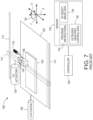
- FIG. 7 depicts a prior art three-dimensional object additive manufacturing system or printer 100 that is configured to operate an extruder 108 to form a three-dimensional printed object 140.
- the printer 100 includes a support member 102, a multi-nozzle extruder 108, extruder support arm 112, controller 128, memory 132, X/Y actuators 150, an optional Z ⁇ actuator 154, and a Z actuator 158.
- the X/Y actuators 150 move the extruder 108 to different locations in a two-dimensional plane (the "X-Y plane") along the X and Y axes to extrude swaths of thermoplastic material that form one layer in a three-dimensional printed object, such as the object 140 that is depicted in FIG. 7 .
- the X/Y actuators 150 translate the support arm 112 and extruder 108 along guide rails 113 to move the arm and extruder along the Y axis while the X/Y actuators 150 translate the extruder 108 along the length of the support arm 112 to move the extruder along the X axis.
- the extruded patterns include both outlines of one or more regions in the layer and swaths of the thermoplastic material that fill the regions within the outline of thermoplastic material patterns.
- the Z actuator 158 controls the distance between the extruder 108 and the support member 102 along the Z axis to ensure that the nozzles in the extruder 108 remain at a suitable height to extrude thermoplastic material onto the object 140 as the object is formed during the printing process.
- the Z ⁇ actuator 154 controls an angle of rotation of the extruder 108 about the Z axis for some embodiments of the extruder 108 that rotate about the Z axis. This movement controls the process and cross-process separation between nozzles in the extruder 108, although some extruders do not require rotation during the manufacturing process.
- the X/Y actuators 150, Z ⁇ actuator 154, and the Z actuator 158 are embodied as electromechanical actuators, such as electric motors, stepper motors, or any other suitable electromechanical device.
- the three-dimensional object printer 100 is depicted during formation of a three-dimensional printed object 140 that is formed from a plurality of layers of thermoplastic material.
- the support member 102 is a planar member, such as a glass plate, polymer plate, or foam surface, which supports the three-dimensional printed object 140 during the manufacturing process.
- the Z actuator 158 also moves the support member 102 in the direction Z away from the extruder 108 after application of each layer of thermoplastic material to ensure that the extruder 108 maintains a predetermined distance from the upper surface of the object 140.
- the extruder 108 includes a plurality of nozzles and each nozzle extrudes thermoplastic material onto the surface of the support member 102 or a surface of a partially formed object, such the object 140.
- extrusion material is provided as a filament from extrusion material supply 110, which is a spool of ABS plastic or another suitable extrusion material filament that unwinds from the spool to supply extrusion material to the extruder 108.
- the support arm 112 includes a support member and one or more actuators that move the extruder 108 during printing operations.
- one or more actuators 150 move the support arm 112 and extruder 108 along the X and Y axes during the printing operation.
- one of the actuators 150 moves the support arm 112 and the extruder 108 along the Y axis while another actuator moves the extruder 108 along the length of the support arm 112 to move along the X axis.
- the X/Y actuators 150 optionally move the extruder 108 along both the X and Y axes simultaneously along either straight or curved paths.
- the controller 128 controls the movements of the extruder 108 in both linear and curved paths that enable the nozzles in the extruder 108 to extrude thermoplastic material onto the support member 102 or onto previously formed layers of the object 140.
- the controller 128 optionally moves the extruder 108 in a rasterized motion along the X axis or Y axis, but the X/Y actuators 150 can also move the extruder 108 along arbitrary linear or curved paths in the X-Y plane.
- the controller 128 is a digital logic device such as a microprocessor, microcontroller, field programmable gate array (FPGA), application specific integrated circuit (ASIC) or any other digital logic that is configured to operate the printer 100.
- the term "controller” means one or more controllers, processors, or computers configured with programmed instructions to form a plurality of tasks to achieve a function.
- a controller for a printer can be multiple controllers that operate the extruder, move the extruder, process the object data, and optimize the filling of regions within an object being manufactured, as well as other tasks and functions.
- the controller 128 is operatively connected to one or more actuators that control the movement of the support member 102 and the support arm 112.
- the controller 128 is also operatively connected to a memory 132.
- the memory 132 includes volatile data storage devices, such as random access memory (RAM) devices, and non-volatile data storage devices such as solid-state data storage devices, magnetic disks, optical disks, or any other suitable data storage devices.
- the memory 132 stores programmed instruction data 134 and three-dimensional (3D) object image data 136.
- the controller 128 executes the stored program instructions 134 to operate the components in the printer 100 to form the three-dimensional printed object 140 and print two-dimensional images on one or more surfaces of the object 140.
- the 3D object image data 136 includes, for example, data defining cross-sectional views of an object on a layer-by-layer basis.
- Each data layer represents a layer of thermoplastic material that the printer 100 forms during the three-dimensional object printing process.
- the extruder path control data 138 include sets of geometric data or actuator control commands that the controller 128 processes to control the path of movement of the extruder 108 using the X/Y actuators 150 and to control the orientation of the extruder 108 using the Z ⁇ actuator 154.
- the controller 128 operates the actuators to move the extruder 108 above the support member 102 as noted above while the extruder extrudes thermoplastic material to form an object.
- FIG. 1 depicts an additive manufacturing system 100' having an extruder 108 that extrudes a plurality of thermoplastic materials through apertures in a faceplate.
- the printer 100' is depicted as a printer that uses planar motion to form an object, other printer architectures can be used with the extruder and the controller configured to regulate speed of the extruder with reference to the angular orientation of the extruder as described in this document. These architectures include delta-bots, selective compliance assembly robot arms (SCARAs), multi-axis printers, non-Cartesian printers, and the like.
- SCARAs selective compliance assembly robot arms
- each manifold 216 in the extruder 108 is operatively connected to a different heater 208 that is fed by a different extrusion material supply 110 in a one-to-one correspondence.
- each manifold 216 can be coupled to a single heater 208' that houses a plurality of channels 232' that are fed by a plurality of extrusion material supplies 110 as shown in the embodiment 100" of FIG. 2 .
- Each channel 232' in FIG. 2 supplies thermoplastic material to a manifold 216 in the extruder 108 to enable each manifold to receive a material that is different than a material that the other manifolds are receiving.
- each nozzle 218 is fluidly connected to only one of the manifolds within the extruder 108 so each nozzle can extrude a thermoplastic material that is different than the materials extruded from nozzles connected to other manifolds.
- Extrusion from each nozzle is selectively and independently activated and deactivated by controller 128 operating the valves in the valve assembly 204.
- Each nozzle 218 is also aligned with an aperture in a faceplate 260 to configure the nozzles for more flexible formation of swaths of the materials in an object.
- a valve assembly 204 positions a valve between the manifolds in the extruder 108 and each of the nozzles connected to the manifolds in the extruder 108.
- the valve assembly 204 is operatively connected to the controller 128 so the controller can open and close the valves for extruding thermoplastic material from the plurality of nozzles in the extruder 108.
- the controller 128 activates and deactivates different actuators in the assembly 204 connected to the valves in the extruder 108 to extrude thermoplastic material from the nozzles and form swaths of different thermoplastic materials in each layer of a three-dimensional printed object, such as object 140 in FIG. 6 .
- the system 100' of FIG. 1 also includes an extrusion material dispensing system 212 for each heater 208 that is connected to a manifold in the extruder 108.
- the extrusion material from each separate supply 110 is fed to the corresponding heater 208 at a rate that maintains the pressure of the thermoplastic material in the manifold connected to the heater within a predetermined range during operation of the system 100'.
- the dispensing system 212 is one embodiment that is suitable for regulating pressure of the thermoplastic material in each manifold of the extruder 108.
- a plurality of extrusion material dispensing systems 212 are operatively connected between a plurality of extrusion material supplies 110 and a channel 232' in the heater 208' in a one-to-one correspondence. Additionally, in both embodiments, the controller 128 is operatively connected to an actuator each dispensing system 212 to control the rate at which the dispensing system 212 delivers extrusion material from a supply 110 to the heater fed by the supply.
- the dispensing systems 212 of FIG. 2 can be configured as the dispensing system 212 of FIG. 1 .
- the heaters 208 and 208' soften or melt the extrusion material 220 fed to the heater 208 via drive roller 224 ( FIG. 1 ).
- Actuator 240 drives the roller 224 and is operatively connected to the controller 128 so the controller can regulate the speed at which the actuator drives the roller 224.
- Another roller opposite roller 224 is free-wheeling so it follows the rate of rotation at which roller 224 is driven.
- FIG. 1 depicts a feed system that uses an electromechanical actuator and the driver roller 224 as a mechanical mover to move the filament 220 into the heater 208 or 208'
- alternative embodiments of the dispensing system 212 use one or more actuators to operate a mechanical mover in the form of a rotating auger or screw.
- the auger or screw moves solid phase extrusion material from a supply 110 in the form of extrusion material powder or pellets into a heater 208 or 208'.
- each heater has a body formed from stainless steel that includes one or more heating elements 228, such as electrically resistive heating elements, which are operatively connected to the controller 128.
- Controller 128 is configured to connect the heating elements 228 to electrical current selectively to soften or melt the filament of extrusion material 220 in the channel or channels within the heater 208 or 208'.
- FIG. 1 and FIG. 2 show heater 208 and heater 208' receiving extrusion material in a solid phase as solid filament 220, in alternative embodiments, the heaters receive the extrusion material in solid phase as powdered or pelletized extrusion material.
- Cooling fins 236 attenuate heat in the channels upstream from the heater.
- a portion of the extrusion material that remains solid in a channel at or near the cooling fins 236 forms a seal in the channel that prevents thermoplastic material from exiting the heater from any opening than the connection to the manifold 216, which maintains a temperature that keeps the extrusion material in a thermoplastic state as it enters the manifold.
- the extruder 108 can also include additional heating elements to maintain an elevated temperature for the thermoplastic material within each manifold within the extruder.
- a thermal insulator covers portions of the exterior of the extruder 108 to maintain a temperature within the manifolds within the extruder. Again, the regions around the nozzles in FIG. 2 are maintained at a temperature that keeps the material in a thermoplastic state so it does not begin solidifying as it travels to the apertures in the faceplate.
- a slip clutch 244 is operatively connected to the drive shaft of each actuator 240 that feeds filament from a supply 110 to a heater.
- the term "slip clutch” refers to a device applies frictional force to an object to move the object up to a predetermined set point. When the range about the predetermined set point for the frictional force is exceeded, the device slips so it no longer applies the frictional force to the object.
- the slip clutch enables the force exerted on the filament 220 by the roller 224 to remain within the constraints on the strength of the filament no matter how frequently, how fast, or how long the actuator 240 is driven.
- This constant force can be maintained by either driving the actuator 240 at a speed that is higher than the fastest expected rotational speed of the filament drive roller 224 or by ⁇ utting an encoder wheel 248 on the roller 224 and sensing the rate of rotation with a sensor 252.
- the signal generated by the sensor 252 indicates the angular rotation of the roller 224 and the controller 128 receives this signal to identify the speed of the roller 224.
- the controller 128 is further configured to adjust the signal provided to the actuator 240 to control the speed of the actuator.
- the controller 128 When the controller is configured to control the speed of the actuator 240, the controller 128 operates the actuator 240 so its average speed is slightly faster than the rotation of the roller 224. This operation ensures that the torque on the drive roller 224 is always a function of the slip clutch torque.
- the controller 128 has a set point stored in memory connected to the controller that identifies the slightly higher speed of the actuator output shaft over the rotational speed of the roller 224.
- the term "set point" means a parameter value that a controller uses to operate components to keep the parameter corresponding to the set point within a predetermined range about the set point.
- the controller 128 changes a signal that operates the actuator 240 to rotate the output shaft at a speed identified by the output signal in a predetermined range about the set point.
- the number of valves opened or closed in the valve assembly 204 and the torque set point for the clutch also affect the filament drive system 212 operation.
- the resulting rotational speed of the roller 224 is identified by the signal generated by the sensor 252.
- a proportional-integral-derivative (PID) controller within controller 128 identifies an error from this signal with reference to the differential set point stored in memory and adjusts the signal output by the controller to operate the actuator 240.
- the controller 128 can alter the torque level for the slip clutch or the controller 128 can both alter the torque level and adjust the signal with which the controller operates the actuator.
- the slip clutch 244 can be a fixed or adjustable torque friction disc clutch, a magnetic particle clutch, a magnetic hysteresis clutch, a ferro-fluid clutch, an air pressure clutch, or permanent magnetic clutch.
- the clutch types that operate magnetically can have their torque set points adjusted by applying a voltage to the clutches. This feature enables the torque set point on the clutch to be changed with reference to print conditions.
- print conditions refers to parameters of the currently ongoing manufacturing operation that affect the amount of thermoplastic material required in the manifold for adequate formation of the object.
- These print conditions include the type of extrusion material being fed to the extruder, the temperature of the thermoplastic material being emitted from the extruder, the speed at which the extruder is being moved in the X-Y plane, the position of the feature being formed on the object, the angle at which the extruder is being moved relative to the platform, and the like.
- the controller 128 is configured as described above with program instructions 134, object image data 136, and extruder head path control data 138 to identify a path of movement for the extruder in different regions of a layer and to transmit one or more signals to the X/Y actuators 150 to move the extruder 108 and to regulate the speed at which the extruder 108 is moved above platform 102.
- the controller 128 in FIG. 1 and FIG. 2 is configured with program instructions and head control data that includes sparse fill patterns and transition patterns that are used with object layer data as discussed in more detail below.
- the controller 128 is configured to regulate the speed of the extruder 108 with reference to the angle of the path at which the extruder 108 is to be moved and the orientation of the extruder faceplate as it moves along that path.
- the controller 128 is also configured with programmed instructions stored in a memory operatively connected to the controller that, when executed by the controller, enable the controller to generate signals for the X-Y actuators 150 that move the extruder 108 along a path that corresponds to the sparse fill and transition patterns as described more fully below.
- the controller 128 retrieves a layer of object data, it identifies the regions within the layer as solid fill regions, transition regions, and interior regions.
- Solid fill regions typically correspond to external surface regions, although they could also correspond to structures that need to be particularly rigid.
- Interior regions are typically sparsely filled regions since they are not observable and to the extent that the extrusion of build material in the region can be avoided, a cost and resource savings is achieved. Solid fill regions, however, cannot be formed directly over sparsely filled interior regions since much of the solid fill region would be unsupported and would fall into the sparsely filled region.
- transition regions are regions were extrusion material is placed at a density that is greater than a sparsely filled region, but not so great that extruded material would fall into the underlying sparsely filled area and be wasted. Transition regions increase in density in the Z-axis direction as they approach a solid fill region.
- the controller 128 identifies a distance between a top layer of a sparsely filled region and a position where a solid fill region is to be formed that corresponds to a number of transition regions needed to provide a top layer with sufficient support for the formation of the solid fill region at its intended position. Since the transition regions rely on the underlying sparsely filled regions for support, the sparsely filled regions need to provide adequate support structure without requiring amounts of extruded material beyond the identified fill percentage for the sparsely filled interior region.
- the controller 128 retrieves object layer data to form a layer of an object
- the controller identifies solid fill regions, transition regions, and sparsely filled regions in the layer data.
- zig-zag patterns are used to guide the extruder and form support structure in these regions.
- FIG. 3A and FIG. 3B illustrate two zig-zag patterns that are used together to sparsely fill an interior area of an object layer and together they form improved supporting structure in sparsely filled areas.
- the term "sparsely fill” means to fill a three-dimensional (3D) interior region of an object to less than 100% and typically less than approximately 50% or less of the volume of the interior region with extruded material.
- FIG. 3A is oriented to form lines that are oriented on average along a 45°-225° axis to the horizontal orientation of the extruder along the 0°-180° axis, as shown in FIG. 8
- the pattern 308 in FIG. 3B is oriented to form lines that are oriented on average at a -45°-135° axis to the horizontal orientation of the extruder along the 0°-180° axis shown in FIG. 8
- the extruder is guided along a zig-zag path that extends from the lower left to the upper right at an average orientation of 45° off the horizontal.
- each path within a zig-zag pattern is comprised of straight portions 312 and angled portions 316.
- the straight portions 312 are oriented for extruder movement along the 0°-180° axis or the 90°-270° axis.
- the length of extruder movement performed with reference to the straight portions 312 in the zig-zag patterns can be altered to correspond with a fill percentage for the region being formed.
- the angled portions 316 are oriented with the 45°-225° axis or the -45°-135° axis.
- the controller 128 selects one of these patterns to form a layer of a support structure in an identified sparsely filled interior region and moves the extruder along a path corresponding to the selected pattern to form swaths.
- swaths formed by the extruder following a line that proceeds from a lower left position to an upper right position in pattern 304 is wide enough to contact the adjacent swath at the angled portions 316 and that the adjacent swaths are typically printed with the extruder following a line that proceeds from the upper right to the lower left.
- the separation shown in the patterns 304 and 308 at the angled positions merely represents the path that the extruder is following and not the widths of the swaths actually produced by the extruder.
- all of the nozzles are open while using either pattern in FIG. 3A and FIG. 3B , although less than all of the nozzles could be open depending upon the size of the interior area and the percentage of fill to be achieved with the two patterns.
- the first selected pattern which can be the pattern in FIG. 3A or FIG. 3B , is used to sparsely fill a portion of a layer within an identified interior region with the swaths identified by the pattern.
- the controller 128 Prior to forming the swaths, the dimensions of the interior region are identified to correspond with the boundaries of an identified interior region in the object layer.
- the controller 128 operates the extruder in the other identified solid fill, sparsely filled, and transition regions of the current layer to finish formation of the object layer.
- the controller 128 retrieves the next layer of the object and the next set of head control data to identify the various types of regions in the layer.
- the controller 128 selects the other zig-zag pattern and operates the extruder in the same manner to form swaths in the complementary direction on the swaths formed during use of the first selected pattern.
- the controller 128 After the second pattern is used for the formation of the swaths in the identified interior region of the current layer, the controller 128 operates the extruder in the other identified solid fill, sparsely filled, and transition regions of the current layer to finish formation of the object layer. The controller 128 then retrieves the next layer of the object and the next set of head control data to identify the various types of regions in the layer. For the interior region in the previous layer where the pattern of FIG. 3B was used, the controller uses the first selected pattern to form the swaths associated with it and then uses the second pattern to form the swaths associated with it.
- This alternation of the two patterns for sparsely filling the interior area in the adjacent layers continues until the top layer of the support structure being formed by the swaths produced with reference to the two zig-zag patterns reaches a predetermined distance from a position where a solid fill structure is to be formed. Once this position is reached, the controller 128 identifies the interior region as a transition region and a set of transition patterns are used to fill in the remaining volume of the interior region area in subsequent layers at an increasing percentage of fill for each layer to provide a supporting surface for the solid fill structure or surface when the solid fill position is reached.
- the alternating building of the swaths formed with reference to the complementary patterns in FIG. 3A or FIG. 3B forms structure with build material extruded at sparsely filled percentages that has greater rigidity and integrity than those previously known formed with material extruded at the same percentages.
- An example of an interior region formed using the pattern 304 from FIG. 3A and the complementary pattern 308 of FIG. 3B is shown from the bottom in FIG. 5A .
- the swaths printed with the first selected pattern and the swaths formed with the second selected pattern form solid corners at the angled portions of the patterns.
- complementary zigzag patterns avoid crossing one another in a manner that makes the swaths discontinuous so the extrusion remains continuous during printing.
- the word "complementary" means swaths oriented at two different angles, one of which is a positive angle deviation from one of the two orthogonal axes for straight line movement of the extruder during swath formation and the other of which is a negative angle deviation from the same orthogonal axis.
- the two patterns shown in FIG. 3A and FIG. 3B are used in an alternating fashion as described above to fill an interior area sparsely. Alternating the use of the patterns ensures that the angled portions of the swaths in the two patterns cross each other to form strong joints between the straight portions. These crossing angled portions help ensure that stronger joints are formed than by using either pattern alone to form joints with the straight portions only.
- the joints formed with the crossing angled portions enable the straight portions of zig-zag swaths to provide significant linear structural support across an interior region of a part at sparsely filled percentages. The strength of each linear structural support is determined by the width of the swaths, which is determined by the number of contiguous open valves in the extruder.
- the number and width of the swaths in a region of a part determines the strength of the structural support in that region. The wider the swaths, the fewer the number of swaths needed to provide a particular level of strength.
- the lengths of the straight portions need not be the same in all straight sections of a pattern. Furthermore, the length of the straight portions of swaths need not be the same in the two directions, horizontal and vertical. That is, the straight swath portions in the horizontal direction can be longer than the straight swath portions in the vertical direction or vice versa. The longer the straight portions of the swaths are in one of either the horizontal or the vertical direction, the fewer supporting structures are necessary in the other of the vertical and horizontal directions. Thus, shorter vertical or horizontal straight portions can be chosen across an interior region of a part where more strength is needed in either the horizontal or vertical directions.
- any square within a zig-zag pattern can be filled with some extrusion pattern.
- This extrusion pattern may be a smaller zig-zag pattern configured to provide some additional strength in a critical portion of a part.
- the extrusion pattern within a square might be some support pattern that does not necessarily provide additional structural strength, but could be useful for reducing the number of transition layers in an interior region or the quality of the transition layers to a solid surface of the part.
- the controller 128 is also configured to operate the actuators to move the extruder differently at the angled portions 316 than it does at the straight portions 312. For one, the controller operates the actuators to move the extruder at the angles for the corners without rotating the extruder. To ensure a solid fill during this movement of the extruder at an angle other than 0° or 90°, the controller 128 operates the actuators 150 to slow the extruder as the opened nozzles extrude material. In an alternative embodiment, the controller 128 and the actuators 150 are configured to rotate the extruder to the optimum angle for the direction of extruder movement at the corners. In this embodiment, the movement of the extruder need not be slowed at the corners.
- the controller 128 alternates the use of the two patterns shown in FIG. 3A and FIG. 3B until a predetermined distance between a top layer of the support structure formed using the two patterns and a bottom layer where a solid fill structure is to be formed over the sparsely filled support structure is detected. At that position, the controller 128 identifies the interior region as a transition region and begins increasing the density of the swaths formed in subsequent layers until the position where the bottom layer of the solid fill structure is reached. Using a variety of techniques, these transition regions are formed in the subsequent layers until the solid fill layer is reached.
- transition region layer formation is now discussed.
- Other techniques or combinations of techniques can be used to achieve a supporting structure capable of resting on structure formed in sparsely filled interior regions and capable of fully supporting the solid fill layers.
- a plurality of different patterns is used to form the transition regions in different layers. These patterns differ from one another in type and in the number of swaths formed with the various patterns.
- a pattern can be used multiple times to extend the widths of the swaths within a layer by increasing the number of open nozzles used to form a swath and by offsetting the extruder from one use in the layer to another use in the layer.
- the extruder can be used to form bridges between swaths.
- transition pattern refers to data used by a controller to move an extruder to form swaths in a volume of an interior region of an object between a sparsely filled interior region and a solid fill structure or surface.
- the patterns 408, 412, 416, and 420 are transition patterns, while pattern 424 is a pattern for formed a solid fill surface.
- pattern 424 is not a transition pattern, but is included for completeness to show the extruder movement for the first solid fill layer.
- the transition patterns are selected by the controller 128 in the order of 408, 412, 416, and 420. Afterwards, pattern 424 is selected to form a solid layer or surface over the swaths formed with the transition patterns.
- the patterns 412 and 420 are used for moving the extruder 108 to form an odd number of swaths in the transition region of a layer for the horizontal and vertical portions of the patterns.
- the patterns 408 and 416 are used for moving the extruder 108 to form an even number of swaths in the transition region of a layer for the horizontal and vertical portions of the patterns.
- the patterns 412 and 420 are zig-zag patterns since they contain angled paths. Though not shown, each zig-zag pattern 412 and 420 has a complementary zig-zag pattern, like FIG. 3A and FIG. 3B as described above, and these complementary patterns can be alternated in the same manner as the sparse fill zig-zag patterns of 3A and 3B to fill the interior region in multiple layers.
- the patterns 408, 416, and 424 are rectilinear patterns since they only contain horizontal and vertical straight paths.
- a square path within these patterns is printed in sequential swaths before moving on to another square.
- the term "zig-zag pattern” means data stored in a memory operatively connected to a controller that operates one or more actuators that move an extruder to enable the controller to guide the extruder along a path corresponding to the data and the path includes movement at an angle other than movement along the 0° or 90° paths.
- the term "rectilinear pattern” means data stored in a memory operatively connected to a controller that operates one or more actuators that move an extruder to enable the controller to guide the extruder along a path corresponding to the data and the path includes movement only along the 0° or 90° paths. Fewer patterns than the ones depicted in FIG. 4 may be needed to build transition structure to a solid surface if the sparse fill percentage is greater and more patterns may be needed if the sparse fill percentage is smaller.
- the same pattern is used a second time to guide the movement of the extruder and form another group of swaths within the same layer with a second set of nozzles open.
- the second set of nozzles includes the first set of nozzles as well as additional nozzles in the extruder.
- the first set of nozzles place material on the material deposited in the layer previously and the additional nozzles in the second set of nozzles deposit material adjacent to the material emitted from the first set of nozzles. Since this additional material is not supported by material previously emitted in the layer, it may sag slightly, but it has enough coherency that it makes the swath formed during the second pattern use slightly wider than the swath formed during the first pattern use. In this manner, the width of swaths in the transition region of a layer can be increased. Subsequent uses of the pattern in this same layer either open the same nozzles of the immediately previous use or additional nozzles are opened.
- the extruder path can be offset by a predetermined amount from the path followed during the immediately previous use of the selected pattern. This offset coupled with the material emitted from the additional nozzles opened that may be added during a use of the pattern aid in joint formation.
- the controller moves the extruder to other regions in the layer to either extrude material at solid fill, sparsely filled, or transition filled percentages.
- the controller 128 is configured with programmed instructions to select pattern 408 for moving the extruder 108 within a transition region of an object being manufactured. As noted above, this pattern is used to form an even number of swaths, namely, two, in the areas between squares in the pattern to enable widening transition swaths conforming to the pattern 408 to be formed as previously described. Once both swaths have been formed for a predetermined number of layers, the controller 128 selects the pattern 412 for extruder movement over the previously generated transition swaths. This pattern is used to form an odd number of swaths, namely, three, to enable widening transition swaths conforming to the pattern 412 to be formed in the layer.
- the controller 128 selects the pattern 416 for extruder movement over the previously generated transition swaths. This pattern is used to form an even number of swaths, namely, four, to enable widening transition swaths conforming to the pattern 416 to be formed in the layer. Once the three swaths have been formed, the controller 128 selects the pattern 420 for extruder movement over the previously generated transition swaths. This pattern is used to form an odd number of swaths, namely, five, to enable widening transition swaths conforming to the pattern 420 to be formed on one another.
- the controller 128 selects the pattern 424 for extruder movement over the previously generated transition swaths.
- This pattern is used to form a solid fill surface that covers the transition swaths in the transition regions and the sparsely filled swaths in the interior region.
- the pattern 424 can also be used to bridge open areas between swaths. Using the pattern 424 to move the extruder with all nozzles opened for each swath formed and slowing movement of the extruder over open regions between underlying swaths forms bridges between swaths.
- This process of bridging is typical in known 3D extrusion manufacturing and can be used to bridge openings between any layers in an object as long as the opening is not so large as to enable the bridging material to fall into the opening.
- An example of a sparsely filled interior region covered by material corresponding to the transition patterns 408 to 420 as described above is shown from the bottom in FIG. 5B .
- FIG. 6 depicts a block diagram of a process 600 for moving and operating an extruder with reference to sparsely fill zig-zag patterns and transition patterns to fill interior regions of a 3D object and form supporting structure in those regions.
- a reference to the process 600 performing a function or action refers to the operation of a controller, such as controller 128, to execute stored program instructions to perform the function or action in association with other components in the printer.
- the process 600 is described in conjunction with the printer 100' of FIG. 1 and printer 100" of FIG. 2 for illustrative purposes.
- the process 600 begins with the controller retrieving object layer data and extruder control data from the memory operatively connected to the controller (block 604).
- the controller identifies a region within the object layer as a solid fill region, a sparsely filled region, or a transition region (block 608).
- a region within the object layer as a solid fill region, a sparsely filled region, or a transition region (block 608).
- an appropriate solid fill pattern is selected and used to guide the extruder while the extruder valves are operated (block 612).
- an appropriate zig-zag pattern is selected and used to guide the extruder while the extruder valves are operated (block 616).
- an appropriate transition pattern is selected and used to guide the extruder while the extruder valves are operated (block 620).
- the process determines whether another region is to be formed in the layer (block 624). If another region is to be formed in the layer, the region type is identified (block 608) and the appropriate pattern is selected and used to form swaths in the identified region (blocks 612, 616, or 620). If no other region is to be formed in the layer, the process determines whether another layer is to be formed (block 628). If so, then the object layer data and extruder control data is retrieved (block 604) and the regions within the layer are processed (blocks 608 to 624). When all of the object layer data has been processed (block 628), the process stops.
Landscapes
- Chemical & Material Sciences (AREA)
- Engineering & Computer Science (AREA)
- Materials Engineering (AREA)
- Manufacturing & Machinery (AREA)
- Physics & Mathematics (AREA)
- Mechanical Engineering (AREA)
- Optics & Photonics (AREA)
- Extrusion Moulding Of Plastics Or The Like (AREA)
Applications Claiming Priority (1)
| Application Number | Priority Date | Filing Date | Title |
|---|---|---|---|
| US15/961,256 US10870235B2 (en) | 2018-04-24 | 2018-04-24 | Method for operating a multi-nozzle extruder using zig-zag patterns that provide improved structural integrity |
Publications (2)
| Publication Number | Publication Date |
|---|---|
| EP3575060A1 EP3575060A1 (en) | 2019-12-04 |
| EP3575060B1 true EP3575060B1 (en) | 2023-03-01 |
Family
ID=66239956
Family Applications (1)
| Application Number | Title | Priority Date | Filing Date |
|---|---|---|---|
| EP19170354.5A Active EP3575060B1 (en) | 2018-04-24 | 2019-04-18 | Method for operating a multi-nozzle extruder using zig-zag patterns that provide improved structual integrity |
Country Status (5)
| Country | Link |
|---|---|
| US (1) | US10870235B2 (enExample) |
| EP (1) | EP3575060B1 (enExample) |
| JP (1) | JP7195997B2 (enExample) |
| KR (1) | KR102493840B1 (enExample) |
| CN (1) | CN110394989B (enExample) |
Families Citing this family (5)
| Publication number | Priority date | Publication date | Assignee | Title |
|---|---|---|---|---|
| US10894358B2 (en) * | 2018-09-13 | 2021-01-19 | Xerox Corporation | Optimized nozzle arrangement for an extruder head used in an additive manufacturing system |
| US20230012165A1 (en) * | 2019-12-03 | 2023-01-12 | Board Of Regents, The University Of Texas System | Seamless printing in fused-filament fabrication of additive manufacturing |
| US11338523B2 (en) * | 2020-06-10 | 2022-05-24 | Xerox Corporation | System and method for operating a multi-nozzle extruder during additive manufacturing |
| US12017409B2 (en) * | 2020-06-10 | 2024-06-25 | Xerox Corporation | Multi-nozzle extruder and method for operating a multi-nozzle extruder during additive manufacturing |
| CN117382170A (zh) * | 2022-07-05 | 2024-01-12 | 苏州美梦机器有限公司 | 3d打印装置及方法 |
Family Cites Families (31)
| Publication number | Priority date | Publication date | Assignee | Title |
|---|---|---|---|---|
| US5740051A (en) | 1991-01-25 | 1998-04-14 | Sanders Prototypes, Inc. | 3-D model making |
| US6129872A (en) * | 1998-08-29 | 2000-10-10 | Jang; Justin | Process and apparatus for creating a colorful three-dimensional object |
| US6682684B1 (en) | 2000-09-07 | 2004-01-27 | Honeywell International Inc. | Procedures for rapid build and improved surface characteristics in layered manufacture |
| US8349239B2 (en) | 2009-09-23 | 2013-01-08 | Stratasys, Inc. | Seam concealment for three-dimensional models |
| US10093039B2 (en) * | 2013-03-08 | 2018-10-09 | Stratasys, Inc. | Three-dimensional parts having interconnected Hollow patterns, method of manufacturing and method of producing composite part |
| US9688028B2 (en) * | 2013-03-22 | 2017-06-27 | Markforged, Inc. | Multilayer fiber reinforcement design for 3D printing |
| US10201929B2 (en) * | 2013-06-12 | 2019-02-12 | Makerbot Industries, Llc | Raft techniques in three-dimensional printing |
| US9669586B2 (en) * | 2013-10-01 | 2017-06-06 | Autodesk, Inc. | Material dispensing system |
| US10618217B2 (en) * | 2013-10-30 | 2020-04-14 | Branch Technology, Inc. | Cellular fabrication and apparatus for additive manufacturing |
| US8827684B1 (en) * | 2013-12-23 | 2014-09-09 | Radiant Fabrication | 3D printer and printhead unit with multiple filaments |
| WO2015102938A1 (en) * | 2013-12-31 | 2015-07-09 | 3M Innovative Properties Company | Volume based gradient index lens by additive manufacturing |
| CN104274867B (zh) * | 2014-03-10 | 2019-09-17 | 北京阿迈特医疗器械有限公司 | 可降解聚合物支架及其成形加工方法与应用 |
| EP3186732B1 (en) * | 2014-08-29 | 2021-11-10 | Microsoft Technology Licensing, LLC | Fabricating three-dimensional objects |
| US20170329878A1 (en) * | 2015-01-30 | 2017-11-16 | Hewlett- Packard Development Company, L.P. | Variable density modeling |
| US20160325498A1 (en) * | 2015-05-04 | 2016-11-10 | Daniel Gelbart | 3D Printer Based on a Staggered Nozzle Array |
| US10532511B2 (en) * | 2015-05-27 | 2020-01-14 | Makerbot Industries, Llc | Infill techniques in three-dimensional printing |
| US20170002467A1 (en) * | 2015-07-02 | 2017-01-05 | Fei Company | Adaptive control for charged particle beam processing |
| US10532552B2 (en) * | 2015-10-23 | 2020-01-14 | Makerbot Industries, Llc | Build patterns for surfaces of a three-dimensionally printed object |
| US10201940B2 (en) * | 2015-11-12 | 2019-02-12 | The Boeing Company | Apparatus and method to predetermine a mechanical property of a three-dimensional object built by additive manufacturing |
| US10456968B2 (en) * | 2015-12-08 | 2019-10-29 | Xerox Corporation | Three-dimensional object printer with multi-nozzle extruders and dispensers for multi-nozzle extruders and printheads |
| US10335991B2 (en) * | 2015-12-08 | 2019-07-02 | Xerox Corporation | System and method for operation of multi-nozzle extrusion printheads in three-dimensional object printers |
| US10625466B2 (en) * | 2015-12-08 | 2020-04-21 | Xerox Corporation | Extrusion printheads for three-dimensional object printers |
| US20190030822A1 (en) * | 2016-01-25 | 2019-01-31 | Mutoh Industries Ltd. | Three-dimensional molding device, method for controlling same, and article molded by same |
| US20180065317A1 (en) * | 2016-09-06 | 2018-03-08 | Cc3D Llc | Additive manufacturing system having in-situ fiber splicing |
| US10682796B2 (en) * | 2016-10-26 | 2020-06-16 | Xerox Corporation | Constant pressure filament driver for extruder heads in three-dimensional object printers |
| US10591897B2 (en) * | 2017-02-21 | 2020-03-17 | Autodesk, Inc. | Systems and methods of reducing curl and wrap in additive manufacturing |
| US11072065B2 (en) * | 2017-03-30 | 2021-07-27 | Wipro Limited | Robotic apparatus for building a multidimensional object |
| CN107876766A (zh) | 2017-11-23 | 2018-04-06 | 攀钢集团攀枝花钢铁研究院有限公司 | 激光烧结扫描方法 |
| CN107932947A (zh) * | 2017-12-18 | 2018-04-20 | 福建铁工机智能机器人有限公司 | 一种3d打印鞋的设备及其使用方法 |
| US10611079B2 (en) * | 2018-02-19 | 2020-04-07 | Arevo, Inc. | Quadrilateral sparse infill made of linear segments of filament |
| US10183442B1 (en) * | 2018-03-02 | 2019-01-22 | Additive Device, Inc. | Medical devices and methods for producing the same |
-
2018
- 2018-04-24 US US15/961,256 patent/US10870235B2/en active Active
-
2019
- 2019-03-29 JP JP2019067205A patent/JP7195997B2/ja active Active
- 2019-04-03 KR KR1020190038867A patent/KR102493840B1/ko active Active
- 2019-04-04 CN CN201910270679.9A patent/CN110394989B/zh active Active
- 2019-04-18 EP EP19170354.5A patent/EP3575060B1/en active Active
Also Published As
| Publication number | Publication date |
|---|---|
| US20190322043A1 (en) | 2019-10-24 |
| CN110394989A (zh) | 2019-11-01 |
| EP3575060A1 (en) | 2019-12-04 |
| KR20190130474A (ko) | 2019-11-22 |
| KR102493840B1 (ko) | 2023-01-30 |
| US10870235B2 (en) | 2020-12-22 |
| JP2019188801A (ja) | 2019-10-31 |
| CN110394989B (zh) | 2022-02-01 |
| JP7195997B2 (ja) | 2022-12-26 |
Similar Documents
| Publication | Publication Date | Title |
|---|---|---|
| EP3486068B1 (en) | System for adjusting the speed of a multi-nozzle extruder during additive manufacturing with reference to an angular orientation of the extruder | |
| EP3575060B1 (en) | Method for operating a multi-nozzle extruder using zig-zag patterns that provide improved structual integrity | |
| KR20180045800A (ko) | 3차원 물체 프린터에서 압출기 헤드용 일정 압력 필라멘트 구동기 | |
| EP3715093B1 (en) | Method for operating an extruder in a three-dimensional (3d) object printer to improve layer formation ane three-diemensional (3d) object printer | |
| JP7416584B2 (ja) | マルチノズル押出機を用いて三次元物体に構造的支持体を提供するシステム及び方法 | |
| US10882250B2 (en) | Additive manufacturing apparatus | |
| EP3922438B1 (en) | System and method for operating a multi-nozzle extruder during additive manufacturing | |
| EP3882004A1 (en) | System and method for operating a multi-nozzle extruder during additive manufacturing |
Legal Events
| Date | Code | Title | Description |
|---|---|---|---|
| PUAI | Public reference made under article 153(3) epc to a published international application that has entered the european phase |
Free format text: ORIGINAL CODE: 0009012 |
|
| STAA | Information on the status of an ep patent application or granted ep patent |
Free format text: STATUS: THE APPLICATION HAS BEEN PUBLISHED |
|
| AK | Designated contracting states |
Kind code of ref document: A1 Designated state(s): AL AT BE BG CH CY CZ DE DK EE ES FI FR GB GR HR HU IE IS IT LI LT LU LV MC MK MT NL NO PL PT RO RS SE SI SK SM TR |
|
| AX | Request for extension of the european patent |
Extension state: BA ME |
|
| STAA | Information on the status of an ep patent application or granted ep patent |
Free format text: STATUS: REQUEST FOR EXAMINATION WAS MADE |
|
| 17P | Request for examination filed |
Effective date: 20200604 |
|
| RBV | Designated contracting states (corrected) |
Designated state(s): AL AT BE BG CH CY CZ DE DK EE ES FI FR GB GR HR HU IE IS IT LI LT LU LV MC MK MT NL NO PL PT RO RS SE SI SK SM TR |
|
| STAA | Information on the status of an ep patent application or granted ep patent |
Free format text: STATUS: EXAMINATION IS IN PROGRESS |
|
| 17Q | First examination report despatched |
Effective date: 20211108 |
|
| GRAP | Despatch of communication of intention to grant a patent |
Free format text: ORIGINAL CODE: EPIDOSNIGR1 |
|
| STAA | Information on the status of an ep patent application or granted ep patent |
Free format text: STATUS: GRANT OF PATENT IS INTENDED |
|
| INTG | Intention to grant announced |
Effective date: 20220923 |
|
| GRAS | Grant fee paid |
Free format text: ORIGINAL CODE: EPIDOSNIGR3 |
|
| GRAA | (expected) grant |
Free format text: ORIGINAL CODE: 0009210 |
|
| STAA | Information on the status of an ep patent application or granted ep patent |
Free format text: STATUS: THE PATENT HAS BEEN GRANTED |
|
| AK | Designated contracting states |
Kind code of ref document: B1 Designated state(s): AL AT BE BG CH CY CZ DE DK EE ES FI FR GB GR HR HU IE IS IT LI LT LU LV MC MK MT NL NO PL PT RO RS SE SI SK SM TR |
|
| REG | Reference to a national code |
Ref country code: GB Ref legal event code: FG4D |
|
| REG | Reference to a national code |
Ref country code: CH Ref legal event code: EP Ref country code: AT Ref legal event code: REF Ref document number: 1550679 Country of ref document: AT Kind code of ref document: T Effective date: 20230315 |
|
| REG | Reference to a national code |
Ref country code: DE Ref legal event code: R096 Ref document number: 602019025737 Country of ref document: DE |
|
| REG | Reference to a national code |
Ref country code: IE Ref legal event code: FG4D |
|
| REG | Reference to a national code |
Ref country code: LT Ref legal event code: MG9D |
|
| REG | Reference to a national code |
Ref country code: NL Ref legal event code: MP Effective date: 20230301 |
|
| PG25 | Lapsed in a contracting state [announced via postgrant information from national office to epo] |
Ref country code: RS Free format text: LAPSE BECAUSE OF FAILURE TO SUBMIT A TRANSLATION OF THE DESCRIPTION OR TO PAY THE FEE WITHIN THE PRESCRIBED TIME-LIMIT Effective date: 20230301 Ref country code: NO Free format text: LAPSE BECAUSE OF FAILURE TO SUBMIT A TRANSLATION OF THE DESCRIPTION OR TO PAY THE FEE WITHIN THE PRESCRIBED TIME-LIMIT Effective date: 20230601 Ref country code: LV Free format text: LAPSE BECAUSE OF FAILURE TO SUBMIT A TRANSLATION OF THE DESCRIPTION OR TO PAY THE FEE WITHIN THE PRESCRIBED TIME-LIMIT Effective date: 20230301 Ref country code: LT Free format text: LAPSE BECAUSE OF FAILURE TO SUBMIT A TRANSLATION OF THE DESCRIPTION OR TO PAY THE FEE WITHIN THE PRESCRIBED TIME-LIMIT Effective date: 20230301 Ref country code: HR Free format text: LAPSE BECAUSE OF FAILURE TO SUBMIT A TRANSLATION OF THE DESCRIPTION OR TO PAY THE FEE WITHIN THE PRESCRIBED TIME-LIMIT Effective date: 20230301 Ref country code: ES Free format text: LAPSE BECAUSE OF FAILURE TO SUBMIT A TRANSLATION OF THE DESCRIPTION OR TO PAY THE FEE WITHIN THE PRESCRIBED TIME-LIMIT Effective date: 20230301 |
|
| REG | Reference to a national code |
Ref country code: AT Ref legal event code: MK05 Ref document number: 1550679 Country of ref document: AT Kind code of ref document: T Effective date: 20230301 |
|
| PG25 | Lapsed in a contracting state [announced via postgrant information from national office to epo] |
Ref country code: SE Free format text: LAPSE BECAUSE OF FAILURE TO SUBMIT A TRANSLATION OF THE DESCRIPTION OR TO PAY THE FEE WITHIN THE PRESCRIBED TIME-LIMIT Effective date: 20230301 Ref country code: PL Free format text: LAPSE BECAUSE OF FAILURE TO SUBMIT A TRANSLATION OF THE DESCRIPTION OR TO PAY THE FEE WITHIN THE PRESCRIBED TIME-LIMIT Effective date: 20230301 Ref country code: NL Free format text: LAPSE BECAUSE OF FAILURE TO SUBMIT A TRANSLATION OF THE DESCRIPTION OR TO PAY THE FEE WITHIN THE PRESCRIBED TIME-LIMIT Effective date: 20230301 Ref country code: GR Free format text: LAPSE BECAUSE OF FAILURE TO SUBMIT A TRANSLATION OF THE DESCRIPTION OR TO PAY THE FEE WITHIN THE PRESCRIBED TIME-LIMIT Effective date: 20230602 Ref country code: FI Free format text: LAPSE BECAUSE OF FAILURE TO SUBMIT A TRANSLATION OF THE DESCRIPTION OR TO PAY THE FEE WITHIN THE PRESCRIBED TIME-LIMIT Effective date: 20230301 |
|
| PG25 | Lapsed in a contracting state [announced via postgrant information from national office to epo] |
Ref country code: SM Free format text: LAPSE BECAUSE OF FAILURE TO SUBMIT A TRANSLATION OF THE DESCRIPTION OR TO PAY THE FEE WITHIN THE PRESCRIBED TIME-LIMIT Effective date: 20230301 Ref country code: RO Free format text: LAPSE BECAUSE OF FAILURE TO SUBMIT A TRANSLATION OF THE DESCRIPTION OR TO PAY THE FEE WITHIN THE PRESCRIBED TIME-LIMIT Effective date: 20230301 Ref country code: PT Free format text: LAPSE BECAUSE OF FAILURE TO SUBMIT A TRANSLATION OF THE DESCRIPTION OR TO PAY THE FEE WITHIN THE PRESCRIBED TIME-LIMIT Effective date: 20230703 Ref country code: EE Free format text: LAPSE BECAUSE OF FAILURE TO SUBMIT A TRANSLATION OF THE DESCRIPTION OR TO PAY THE FEE WITHIN THE PRESCRIBED TIME-LIMIT Effective date: 20230301 Ref country code: CZ Free format text: LAPSE BECAUSE OF FAILURE TO SUBMIT A TRANSLATION OF THE DESCRIPTION OR TO PAY THE FEE WITHIN THE PRESCRIBED TIME-LIMIT Effective date: 20230301 Ref country code: AT Free format text: LAPSE BECAUSE OF FAILURE TO SUBMIT A TRANSLATION OF THE DESCRIPTION OR TO PAY THE FEE WITHIN THE PRESCRIBED TIME-LIMIT Effective date: 20230301 |
|
| PG25 | Lapsed in a contracting state [announced via postgrant information from national office to epo] |
Ref country code: SK Free format text: LAPSE BECAUSE OF FAILURE TO SUBMIT A TRANSLATION OF THE DESCRIPTION OR TO PAY THE FEE WITHIN THE PRESCRIBED TIME-LIMIT Effective date: 20230301 Ref country code: IS Free format text: LAPSE BECAUSE OF FAILURE TO SUBMIT A TRANSLATION OF THE DESCRIPTION OR TO PAY THE FEE WITHIN THE PRESCRIBED TIME-LIMIT Effective date: 20230701 |
|
| REG | Reference to a national code |
Ref country code: CH Ref legal event code: PL |
|
| REG | Reference to a national code |
Ref country code: DE Ref legal event code: R097 Ref document number: 602019025737 Country of ref document: DE |
|
| PG25 | Lapsed in a contracting state [announced via postgrant information from national office to epo] |
Ref country code: LU Free format text: LAPSE BECAUSE OF NON-PAYMENT OF DUE FEES Effective date: 20230418 |
|
| PLBE | No opposition filed within time limit |
Free format text: ORIGINAL CODE: 0009261 |
|
| STAA | Information on the status of an ep patent application or granted ep patent |
Free format text: STATUS: NO OPPOSITION FILED WITHIN TIME LIMIT |
|
| REG | Reference to a national code |
Ref country code: BE Ref legal event code: MM Effective date: 20230430 |
|
| PG25 | Lapsed in a contracting state [announced via postgrant information from national office to epo] |
Ref country code: MC Free format text: LAPSE BECAUSE OF FAILURE TO SUBMIT A TRANSLATION OF THE DESCRIPTION OR TO PAY THE FEE WITHIN THE PRESCRIBED TIME-LIMIT Effective date: 20230301 |
|
| PG25 | Lapsed in a contracting state [announced via postgrant information from national office to epo] |
Ref country code: SI Free format text: LAPSE BECAUSE OF FAILURE TO SUBMIT A TRANSLATION OF THE DESCRIPTION OR TO PAY THE FEE WITHIN THE PRESCRIBED TIME-LIMIT Effective date: 20230301 Ref country code: MC Free format text: LAPSE BECAUSE OF FAILURE TO SUBMIT A TRANSLATION OF THE DESCRIPTION OR TO PAY THE FEE WITHIN THE PRESCRIBED TIME-LIMIT Effective date: 20230301 Ref country code: LI Free format text: LAPSE BECAUSE OF NON-PAYMENT OF DUE FEES Effective date: 20230430 Ref country code: DK Free format text: LAPSE BECAUSE OF FAILURE TO SUBMIT A TRANSLATION OF THE DESCRIPTION OR TO PAY THE FEE WITHIN THE PRESCRIBED TIME-LIMIT Effective date: 20230301 Ref country code: CH Free format text: LAPSE BECAUSE OF NON-PAYMENT OF DUE FEES Effective date: 20230430 |
|
| 26N | No opposition filed |
Effective date: 20231204 |
|
| REG | Reference to a national code |
Ref country code: IE Ref legal event code: MM4A |
|
| PG25 | Lapsed in a contracting state [announced via postgrant information from national office to epo] |
Ref country code: BE Free format text: LAPSE BECAUSE OF NON-PAYMENT OF DUE FEES Effective date: 20230430 |
|
| PG25 | Lapsed in a contracting state [announced via postgrant information from national office to epo] |
Ref country code: IE Free format text: LAPSE BECAUSE OF NON-PAYMENT OF DUE FEES Effective date: 20230418 |
|
| PG25 | Lapsed in a contracting state [announced via postgrant information from national office to epo] |
Ref country code: IE Free format text: LAPSE BECAUSE OF NON-PAYMENT OF DUE FEES Effective date: 20230418 |
|
| PGFP | Annual fee paid to national office [announced via postgrant information from national office to epo] |
Ref country code: GB Payment date: 20240321 Year of fee payment: 6 |
|
| PG25 | Lapsed in a contracting state [announced via postgrant information from national office to epo] |
Ref country code: IT Free format text: LAPSE BECAUSE OF FAILURE TO SUBMIT A TRANSLATION OF THE DESCRIPTION OR TO PAY THE FEE WITHIN THE PRESCRIBED TIME-LIMIT Effective date: 20230301 |
|
| PGFP | Annual fee paid to national office [announced via postgrant information from national office to epo] |
Ref country code: FR Payment date: 20240320 Year of fee payment: 6 |
|
| PGFP | Annual fee paid to national office [announced via postgrant information from national office to epo] |
Ref country code: DE Payment date: 20240320 Year of fee payment: 6 |
|
| PG25 | Lapsed in a contracting state [announced via postgrant information from national office to epo] |
Ref country code: BG Free format text: LAPSE BECAUSE OF FAILURE TO SUBMIT A TRANSLATION OF THE DESCRIPTION OR TO PAY THE FEE WITHIN THE PRESCRIBED TIME-LIMIT Effective date: 20230301 |
|
| PG25 | Lapsed in a contracting state [announced via postgrant information from national office to epo] |
Ref country code: BG Free format text: LAPSE BECAUSE OF FAILURE TO SUBMIT A TRANSLATION OF THE DESCRIPTION OR TO PAY THE FEE WITHIN THE PRESCRIBED TIME-LIMIT Effective date: 20230301 |
|
| PG25 | Lapsed in a contracting state [announced via postgrant information from national office to epo] |
Ref country code: CY Free format text: LAPSE BECAUSE OF FAILURE TO SUBMIT A TRANSLATION OF THE DESCRIPTION OR TO PAY THE FEE WITHIN THE PRESCRIBED TIME-LIMIT; INVALID AB INITIO Effective date: 20190418 |
|
| PG25 | Lapsed in a contracting state [announced via postgrant information from national office to epo] |
Ref country code: HU Free format text: LAPSE BECAUSE OF FAILURE TO SUBMIT A TRANSLATION OF THE DESCRIPTION OR TO PAY THE FEE WITHIN THE PRESCRIBED TIME-LIMIT; INVALID AB INITIO Effective date: 20190418 |