EP3574654B1 - System and method for controlling media content capture for live video broadcast production - Google Patents
System and method for controlling media content capture for live video broadcast production Download PDFInfo
- Publication number
- EP3574654B1 EP3574654B1 EP18702247.0A EP18702247A EP3574654B1 EP 3574654 B1 EP3574654 B1 EP 3574654B1 EP 18702247 A EP18702247 A EP 18702247A EP 3574654 B1 EP3574654 B1 EP 3574654B1
- Authority
- EP
- European Patent Office
- Prior art keywords
- media streams
- video
- encoding format
- production
- media content
- Prior art date
- Legal status (The legal status is an assumption and is not a legal conclusion. Google has not performed a legal analysis and makes no representation as to the accuracy of the status listed.)
- Active
Links
Images


Classifications
-
- H—ELECTRICITY
- H04—ELECTRIC COMMUNICATION TECHNIQUE
- H04N—PICTORIAL COMMUNICATION, e.g. TELEVISION
- H04N21/00—Selective content distribution, e.g. interactive television or video on demand [VOD]
- H04N21/20—Servers specifically adapted for the distribution of content, e.g. VOD servers; Operations thereof
- H04N21/21—Server components or server architectures
- H04N21/218—Source of audio or video content, e.g. local disk arrays
- H04N21/21805—Source of audio or video content, e.g. local disk arrays enabling multiple viewpoints, e.g. using a plurality of cameras
-
- H—ELECTRICITY
- H04—ELECTRIC COMMUNICATION TECHNIQUE
- H04N—PICTORIAL COMMUNICATION, e.g. TELEVISION
- H04N21/00—Selective content distribution, e.g. interactive television or video on demand [VOD]
- H04N21/20—Servers specifically adapted for the distribution of content, e.g. VOD servers; Operations thereof
- H04N21/21—Server components or server architectures
- H04N21/218—Source of audio or video content, e.g. local disk arrays
- H04N21/2187—Live feed
-
- H—ELECTRICITY
- H04—ELECTRIC COMMUNICATION TECHNIQUE
- H04N—PICTORIAL COMMUNICATION, e.g. TELEVISION
- H04N21/00—Selective content distribution, e.g. interactive television or video on demand [VOD]
- H04N21/20—Servers specifically adapted for the distribution of content, e.g. VOD servers; Operations thereof
- H04N21/21—Server components or server architectures
- H04N21/222—Secondary servers, e.g. proxy server, cable television Head-end
-
- H—ELECTRICITY
- H04—ELECTRIC COMMUNICATION TECHNIQUE
- H04N—PICTORIAL COMMUNICATION, e.g. TELEVISION
- H04N21/00—Selective content distribution, e.g. interactive television or video on demand [VOD]
- H04N21/20—Servers specifically adapted for the distribution of content, e.g. VOD servers; Operations thereof
- H04N21/23—Processing of content or additional data; Elementary server operations; Server middleware
- H04N21/234—Processing of video elementary streams, e.g. splicing of video streams or manipulating encoded video stream scene graphs
- H04N21/23418—Processing of video elementary streams, e.g. splicing of video streams or manipulating encoded video stream scene graphs involving operations for analysing video streams, e.g. detecting features or characteristics
-
- H—ELECTRICITY
- H04—ELECTRIC COMMUNICATION TECHNIQUE
- H04N—PICTORIAL COMMUNICATION, e.g. TELEVISION
- H04N21/00—Selective content distribution, e.g. interactive television or video on demand [VOD]
- H04N21/20—Servers specifically adapted for the distribution of content, e.g. VOD servers; Operations thereof
- H04N21/23—Processing of content or additional data; Elementary server operations; Server middleware
- H04N21/234—Processing of video elementary streams, e.g. splicing of video streams or manipulating encoded video stream scene graphs
- H04N21/2343—Processing of video elementary streams, e.g. splicing of video streams or manipulating encoded video stream scene graphs involving reformatting operations of video signals for distribution or compliance with end-user requests or end-user device requirements
- H04N21/234363—Processing of video elementary streams, e.g. splicing of video streams or manipulating encoded video stream scene graphs involving reformatting operations of video signals for distribution or compliance with end-user requests or end-user device requirements by altering the spatial resolution, e.g. for clients with a lower screen resolution
-
- H—ELECTRICITY
- H04—ELECTRIC COMMUNICATION TECHNIQUE
- H04N—PICTORIAL COMMUNICATION, e.g. TELEVISION
- H04N21/00—Selective content distribution, e.g. interactive television or video on demand [VOD]
- H04N21/20—Servers specifically adapted for the distribution of content, e.g. VOD servers; Operations thereof
- H04N21/23—Processing of content or additional data; Elementary server operations; Server middleware
- H04N21/242—Synchronisation processes, e.g. processing of PCR [Programme Clock References]
-
- H—ELECTRICITY
- H04—ELECTRIC COMMUNICATION TECHNIQUE
- H04N—PICTORIAL COMMUNICATION, e.g. TELEVISION
- H04N21/00—Selective content distribution, e.g. interactive television or video on demand [VOD]
- H04N21/20—Servers specifically adapted for the distribution of content, e.g. VOD servers; Operations thereof
- H04N21/25—Management operations performed by the server for facilitating the content distribution or administrating data related to end-users or client devices, e.g. end-user or client device authentication, learning user preferences for recommending movies
- H04N21/262—Content or additional data distribution scheduling, e.g. sending additional data at off-peak times, updating software modules, calculating the carousel transmission frequency, delaying a video stream transmission, generating play-lists
-
- H—ELECTRICITY
- H04—ELECTRIC COMMUNICATION TECHNIQUE
- H04N—PICTORIAL COMMUNICATION, e.g. TELEVISION
- H04N21/00—Selective content distribution, e.g. interactive television or video on demand [VOD]
- H04N21/60—Network structure or processes for video distribution between server and client or between remote clients; Control signalling between clients, server and network components; Transmission of management data between server and client, e.g. sending from server to client commands for recording incoming content stream; Communication details between server and client
- H04N21/63—Control signaling related to video distribution between client, server and network components; Network processes for video distribution between server and clients or between remote clients, e.g. transmitting basic layer and enhancement layers over different transmission paths, setting up a peer-to-peer communication via Internet between remote STB's; Communication protocols; Addressing
- H04N21/643—Communication protocols
- H04N21/64322—IP
-
- H—ELECTRICITY
- H04—ELECTRIC COMMUNICATION TECHNIQUE
- H04N—PICTORIAL COMMUNICATION, e.g. TELEVISION
- H04N21/00—Selective content distribution, e.g. interactive television or video on demand [VOD]
- H04N21/80—Generation or processing of content or additional data by content creator independently of the distribution process; Content per se
- H04N21/85—Assembly of content; Generation of multimedia applications
- H04N21/854—Content authoring
- H04N21/8547—Content authoring involving timestamps for synchronizing content
-
- H—ELECTRICITY
- H04—ELECTRIC COMMUNICATION TECHNIQUE
- H04N—PICTORIAL COMMUNICATION, e.g. TELEVISION
- H04N5/00—Details of television systems
- H04N5/222—Studio circuitry; Studio devices; Studio equipment
- H04N5/262—Studio circuits, e.g. for mixing, switching-over, change of character of image, other special effects ; Cameras specially adapted for the electronic generation of special effects
- H04N5/268—Signal distribution or switching
Definitions
- the present disclosure generally relates to video and media production, and, more particularly, to a system and method for bending time of live production.
- US2012/320196 discloses methods, systems, apparatus, means and computer program products which allow the remote production of live events by capturing, at a remote event site, event video data in a first time horizon.
- US2014/320662 discloses a computer-implemented method in which cameras at a live event can be remotely controlled by a user device having one or more processors and memory storing one or more programs for execution by the one or more processor.
- WO2014/191990 discloses a method for producing a stream of desired image frames derived from a panoramic capturing of a scene by an array of video cameras.
- Live television broadcasting typically involves capturing media content from a live scene (e.g., a sports venue, news broadcast, etc.), transmitting the captured content to a remote production facility where the video and audio signals are managed by production switchers, and then encoding the signals for transport to a distribution network.
- a live scene e.g., a sports venue, news broadcast, etc.
- Each step in this process involves a certain level of delay, which, as a result, means that live television broadcasts today are far from being actually “live” or in "real-time”.
- typical transmission delay times can range from a few seconds to tens of seconds, which is the time delay between when media content is captured to when a program is transmitted and ultimately viewed by the end consumer. Moreover, this delay can be variable.
- Fig. 1 illustrates a block diagram of a conventional system for producing a live television broadcast.
- the system can include a plurality of cameras 21A and 21B (two cameras are shown, but there can be multiple media streams generated by cameras) that capture media content from a venue 10 (e.g., a sports venue) and provide media streams 22A and 22B to a local encoder 30.
- the encoder 30 in turn encodes the media streams and provides the media as contribution feeds to a remote production facility 31 using satellite communication, for example.
- the production facility 31 will typically include video production equipment 11 that can be composed of production switches, controllers, processors, timing modules, a codec, and other equipment provided to process the incoming media streams for a television broadcast production.
- a technical director 12 can be located at the remote production facility 31 to control the video switcher(s) and make editorial and artistic decisions for the video production.
- One significant technical problem with this arrangement is limited available bandwidth at venues to transmit the contribution feeds to the remote production facility.
- the available bandwidth may only be 1 GbE, for example.
- broadcast production will necessarily be limited to a minimum number of media streams that can provided by cameras 21A and 22B and may even be limited in the resolution of the video production that can be transmitted to the facility.
- encoded high definition (HD) signals may consume too much bandwidth and create unacceptable latency periods.
- the broadcast system shown in Fig. 1 is quite limited in video production capabilities for live broadcast and cannot handle many cameras and/or incoming media streams.
- Fig. 2 illustrates a block diagram of another system for producing a conventional live television broadcast.
- a television network may move both the video production equipment 11 and technical director 12 to the location of the venue 10 using a production truck 10, for example.
- this arrangement is also not ideal from a live video production perspective.
- the technical director 12 may have difficulty within the small confines of the truck 10 viewing the many media streams from the various cameras and manage/control the video switcher accordingly.
- the technical director 12 will typically operate the video switcher (and associated devices) and also serve as the chief of the production crew. Using the video switcher, the technical director 12 will switch video sources and also perform live digital effects and transitions, and insert prerecorded material, graphics and titles. In live video broadcast productions, the technical director 12 must coordinate the production and make rapid decisions. Thus, referring back to the configuration shown in Fig. 1 , if the technical director 12 is located in a production control room of the remote production facility 31, the technical director 12 will often issue control decisions 32 that are fed back to cameras 21A and/or 21B to adjust the capture of media content, such as shading, video capture angles, etc. However, this control process creates further time delay in the video broadcast.
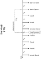
- Fig. 3 illustrates a timing diagram of a conventional system for producing a live television broadcast. Time is shown along the X axis with the starting point in time being the real time event, which would be from a perspective of a person actually attending the sporting event at the venue 10, for example. Albeit small, there will even be a first delay T 1 from when light is captured by the camera lens and the pixel data is output. Moreover, as further shown, there are delays at each stage of the process. For example, there is a second delay T 2 from the camera(s) to the encoder 30 and a third delay T 3 when the signal is decoded at the remote production facility 31 before each media stream can be presented to the technical director after a fourth delay T 4 . Although each delay is shown as being identical, it should be appreciated that the delays will vary according to bandwidth constraints and other propagation delays, such as device processing, conductor impedance of network links, and the like.
- the technical director 12 can then operate the video switcher to issue control commands back to the local equipment (e.g., cameras 21A and 21B) at the venue 10.
- these command signals will also experience an effective delay T control when they are fed back to the devices.
- each subsequent step of production, encoding at the production facility, decoding (by a STB, for example) and ultimate playout by an end consumer device each experiences an additional delay.
- the time delay T control is unacceptable from the consuming perspective as the technical director's editorial decisions will not be based on the actual live events (in real time or close thereto), but only after viewing a delayed image of the events. This results in uncertainty, and missing certain actions during the event, which then detracts from the end consumer's experience.
- a live video broadcasting environment is needed that exploits virtualization techniques so that the end consumer is provided with the illusion that the live event is being produced in real time.
- a system and method that "bends" time of live production. More particularly, the system and method disclosed herein exploits time shifting at the point of origination where cameras capture media in real time, but all media streams are presented coherently to the creative talent (e.g., a technical director) with as short a delay as possible, and preferably, only a few frames.
- creative talent e.g., a technical director
- the production environment provided by the disclosed system and method is a proxy of live, but so close to real time it is perceived as live.
- the use of video optimized equipment and leased data services provides the ability to generate the proxy environment, with a very short delay, and also provides the ability for the video production optimized data center to be reused by many different events and at many different times.
- final live video broadcast production can occur with an additional delay at a generic data center, which can save costs and provide wider scale of resources.
- the disclosed system and method is implemented in order to co-locate final transmission with final production enabling cloud streaming distribution.
- the disclosed system effectively provides a true cloud based data center which can then provide a proxy back to the original production control center, which would be equivalent to a typical broadcast, or satellite, turn around.
- a typical broadcast, or satellite In the case of satellite, it will be faster while in the case of a tower, the turnaround delay will be slower, but only by a few hundred milliseconds.
- using emerging, low latency streaming technologies enables the production engine to reside in a true cloud, not just a private cloud.
- the exemplary system and method provides for the once "on-site production" control room (e.g., a production truck described above serving as both production engine and control room) to become both a virtualized control room, operating with proxies and minimal latency, and a virtualized production engine, operating with high quality media, albeit longer delay than the control room. Therefore, either the control room or the production engine, can be located anywhere provided the delays associated with original content delivery and control decision responsiveness are acceptable.
- a production truck described above serving as both production engine and control room
- the present invention as claimed is directed to a system for minimizing delay time for controlling media content capture during live video broadcast production, the system comprising:
- processors include microprocessors, microcontrollers, graphics processing units (GPUs), central processing units (CPUs), application processors, digital signal processors (DSPs), reduced instruction set computing (RISC) processors, systems on a chip (SoC), baseband processors, field programmable gate arrays (FPGAs), programmable logic devices (PLDs), state machines, gated logic, discrete hardware circuits, and other suitable hardware configured to perform the various functionality described throughout this disclosure.
- processors in the processing system may execute software.
- Software shall be construed broadly to mean instructions, instruction sets, code, code segments, program code, programs, subprograms, software components, applications, software applications, software packages, routines, subroutines, objects, executables, threads of execution, procedures, functions, etc., whether referred to as software, firmware, middleware, microcode, hardware description language, or otherwise.
- the functions and algorithms described herein may be implemented in hardware, software, or any combination thereof. If implemented in software, the functions may be stored on or encoded as one or more instructions or code on a computer-readable medium.
- Computer-readable media may include transitory or non-transitory computer storage media for carrying or having computer-executable instructions or data structures stored thereon. Both transitory and non-transitory storage media may be any available media that can be accessed by a computer as part of the processing system.
- such computer-readable media can comprise a random-access memory (RAM), a read-only memory (ROM), an electrically erasable programmable ROM (EEPROM), optical disk storage, magnetic disk storage, other magnetic storage devices, combinations of the aforementioned types of computer-readable media, or any other medium that can be used to store computer executable code in the form of instructions or data structures that can be accessed by a computer.
- RAM random-access memory
- ROM read-only memory
- EEPROM electrically erasable programmable ROM
- optical disk storage magnetic disk storage
- magnetic disk storage other magnetic storage devices
- combinations of the aforementioned types of computer-readable media or any other medium that can be used to store computer executable code in the form of instructions or data structures that can be accessed by a computer.
- RAM random-access memory
- ROM read-only memory
- EEPROM electrically erasable programmable ROM
- optical disk storage magnetic disk storage
- magnetic disk storage other magnetic storage devices
- Fig. 4A illustrates a block diagram of a system for controlling media content capture for live television production according to an exemplary embodiment.
- certain components illustrated in system 100 correspond to components utilized in existing broadcast production environments as described above.
- a plurality of cameras e.g., cameras 21A and 21B
- a venue 10 such as a sports venue.
- the cameras 21A and 21B as shown as the exemplary media capture devices, one or more of these devices could also include microphones or other types of media originating devices, for example, configured to capture audio data from the live event, in one exemplary aspect.
- the technical director 12 can be located at a remote control center 130 that can include certain video production equipment 11, including a video switcher, for example.
- the media streams of the captured media content which can include image data, graphics and/or replays, for example, generated by the cameras 21A and 22B (and possibly other media capture devices) are provided to one or more encoders 120A and 120B.
- encoders 120A and 120B can be considered broadcast control encoders in that they are configured to encode the data streams from the plurality of cameras 21A and 21B in a first encoding format, such as having a first resolution, for example, to generate high speed proxy signals.
- these high speed proxy signals will include the encoded media content that is suitable for broadcast production control, but not in a format suitable video broadcast production that is presented on consumer devices.
- the design for encoding the media content in a first encoding format enables higher speeds of transmission than if the captured content is transmitted in a format (e.g., high definition or 4K resolution) suitable for consumption by end users.
- the encoders 120A and 120B can be codec devices configured to encode the video data (i.e., the video streams 22A and 22B) into data packets for transmission over IP in the media processing network. More particularly, the encoders 120A and 120B are configured to generate high speed proxy signals that are fed to the video control center 130 where they can be decoded and presented to the technical director 12. In other words, unlike conventional broadcast environments, the encoders 120A and 120B are configured to generate low latency proxy streams that consume minimal bandwidth and, therefore, can be provided to the technical director 12 with minimal latency.
- the high speed encoding by encoders 120A and 120B should be based on a much lower resolution image (compared with the final high resolution output), and then encoded using intra frame coding.
- the encoding can be based on standard-definition television resolution, running at 270 Mb/s, and Q-CIF (quarter common intermediate format) in one exemplary aspect, for example.
- This pre-scale of media followed by encoding compression using H.264 and/or H.265 (HVEC) compression can provide significant reduction in bandwidth consumption, which facilitates the transmission of the high speed media proxies.
- the high speed proxy streams can be transmitted using existing streaming technologies over the Internet, cloud, etc.
- technologies such as Aspera's Fasp or ZiXi streaming, can be implemented to manage network traffic across the Internet, providing minimal latency such as 100 to 200 millisecond.
- these transmission technologies are fast enough to stream either lightly compressed media, such as the proxy streams, or heavily compressed media to a cloud computing resource for video production, if desired.
- the encoders 120A and 120B are configured to generate the high speed proxy signals as standard or low resolution signals.
- the cameras 21A and/or 21B or the encoders 120A and 120B can perform object based analysis of the objects (e.g., people, players, etc.) in the captured media content and provide a real-time, ultra-low bandwidth, and, therefore, low latency proxy signal to the video control center 130.
- the received information i.e., the high speed media proxies
- the technical director 12 can be presented on a multi-view interface at the control center in a first resolution that corresponds to first encoding format of the generated media streams.
- the content can be presented on the interface as avatars that are rendered on the equipment interfaces/monitors based on their spatial orientation and relative motion, which can be continuously observed.
- each media stream can be rendered as part of a workstation having an interface with a multi-viewer display with integrated tally.
- the system can generate simultaneous proxy content that can be remotely viewed and controlled.
- the technical director 12 can make the control decisions based on this rendering using the video switcher controller.
- video production equipment 11 located at the video control center 130 is operated by the user (e.g., the technical director 12) to control the operation of the plurality of cameras 21A and 21B to control media capture content.
- the video production equipment 11 can include a video switch controller coupled to the multi-view interface that receive control instructions generated from a user input via the multi-view interface to control capture of the media content.
- controls are transmitted back to the cameras 21A and 21B via command paths, which reflect the editorial and artistic decisions made by the technical director 12.
- the disclosed system 100 presents the technical director 12 with the necessary media stream proxies with minimal signal delay, such as 100 millisecond or 200 milliseconds, or less, for example.
- the technical director 12 will be able to make the artistic and editorial decisions using the video switcher, much closer to real time.
- the video production equipment 11 can include, for example, a video production receiver that receives the encoded media content streams (e.g., the high speed proxies) from the encoders 120A and 120B coupled to the field cameras, where the encoded media content streams include live media content captured by the cameras and that is encoded in the first high speed encoding format.
- the video production equipment 11 includes the multi-view interface that displays the captured media content from media content streams based on the first encoding format (e.g., in a first resolution as discussed above).
- the video production equipment 11 can further include a video production controller that generates the control instructions, as discussed above, that are based on inputs (e.g., by the technical director 12) to the multi-view interface in order to make on the fly changes to control and modify the operation of the cameras during the capture of the media content at the live event, such as camera control operations like zoom, pan, or the like, as would be appreciated to one skilled in the art.
- the video production equipment 11 can also include a camera controller (or content capture controller) that in turn transmits the generated control instructions to the cameras (or operators of the cameras) that control and change the operation for capturing the media content.
- the video production controller of the video production equipment 11 controls production of the live video stream for video broadcast production using the media content that is captured from the cameras and that is encoded in the second encoding format, which is different than the first encoding format and is suitable for video broadcast production to end consumer devices.
- the system 100 includes a standard encoder 140 (preferably located at the venue 10) that is coupled to encoders 120A and 120B, which can provide high quality signals (e.g., high definition, 4K resolution, etc.) for the production engine in the production environment.
- the standard encoder 140 is a broadcast production encoder that encodes, as a video broadcast media streams, the respective media stream generated by the plurality of cameras, which are controlled by the control instructions, for example, with the video broadcast media stream being encoded in a second encoding format at a second resolution higher than the first resolution used for the high speed media proxies.
- the production environment e.g., the production truck 10
- the production environment can separately feed back to the video control center 130 a high resolution signal that will reflect editorial decisions previously made by the technical director 12 using the low bandwidth, high speed proxy signals.
- the high resolution signal or more typically signals, can arrive at the video production engine(s), with the correct mutual time alignment, and now latency is irrelevant.
- the high resolution signals can be encoded as contribution feeds and the encoder 140 may encode video and audio data using existing video compression techniques, such as, for example, high efficiency video coding ("HEVC"), MPEG-4, or the like using high level high profile settings, such as 4:2:2 10 bit encoding.
- HEVC high efficiency video coding
- MPEG-4 MPEG-4
- the audio and video maybe encoded on a "per stream" basis using the appropriate technology to align with the decoder located at the receiver which requested the stream.
- the encoder 140 can receive the media content directly from the media capturing devices (e.g., cameras 21A and 21B) rather than as encoded signals from encoders 120A and 120B.
- the video control center 130 based on the command instructions issued by the technical director 12 using the video production equipment 11 (e.g., the video switcher controller), provides control decisions that need to be time aligned to the media streams, which are then mutually time aligned at the point of production, in time alignment and processing component 150, which can be located at the venue 10 in a production truck 10 or, alternatively, in the cloud.
- the time alignment and processing component 150 also receives the high resolution signals from standard encoder 140 and is configured to generate the video production, i.e., the live video broadcast production.
- the production truck 10 can be communicatively coupled to one or a plurality of remote distribution nodes, which may distribute the video production using existing distribution techniques to end consumer devices, including a final feedback to the video control center 130 (shown as the high resolution signal being transmitted from production 10 to video control center 130).
- the cameras e.g., cameras 21A and 21B
- the technical director 12 located at a control center 130 remote to the venue 10 can make editorial decisions using the video switcher that are essentially in real-time (e.g., 100 to 200 millisecond latency, or shorter) because the low latency signals are received with minimal delay.
- the system 100 provides full resolution output of the video broadcast while enabling the remote control center 130 to edit the show using the proxy content received from encoders 120A and 120B, while simultaneously controlling the full resolution production equipment (e.g., time alignment and processing component 150) at the venue 10.
- a production environment could provide for a 4K production with, for example, six cameras, four channels of replay and two channels of graphics, using minimal outgoing bandwidth
- the actual video production engine can be located anywhere, such as a central production facility or data center, for example. Either embodiment would also greatly reduce the required production crew personnel at the venue.
- virtualization uses time shifting and masking techniques to provide the illusion of real time.
- virtual reality relies on providing an immersive experience to recreate the necessary senses, in the correct combination, to optimize the virtual experience.
- the technical director's senses are correctly immersed, the entire control room environment may be time shifted from real-time without affecting their user experience and perception.
- the technical director's virtual experience is time-shifted by a small amount, then the end users experience may be substantially time shifted from that of the technical director.
- command signals enable the mutual alignment of media and control to ensure the desired production is carried out, based on real time decisions, but at some arbitrary later point in time that can be a measured or preset offset. This same logic is applied to the technical director's experience, except that their offset, measured or preset, can be set to much less than that of the production media since the media signal are transmitted as high speed proxy signals to the video control center 130.
- the virtualization effect from the perspective of the end consumer is lost due to the length in time of the control signal T control from the video switcher back to the media capture devices, such as the cameras.
- conventional remote live broadcast environments for example, as shown in Fig. 1 , inherently have significant latency between the actual real-time event and when the technical director 12 makes the editorial decisions due to the bandwidth limitations at the venue, for example.
- the unacceptable delay in the generation and transmission of the control signals back to media capture devices creates a delay that can be perceived by the end consumer, especially if the end user is consuming the live event using two separate channels, broadcasts, etc.
- the disclosed system effectively minimizes the time delay T control of the control signal by providing high speed proxy signals of the media streams to the video control center 130 enabling the technical director 12 to make editorial decisions very close to real time.
- these low latency proxy signals can be generated using object detection rather than encoding the full high resolution signals.
- the disclosed design preferably provides a latency below 100 to 200 milliseconds, or less. Therefore, the time delay T control of the control signal can be minimized (assuming the editorial decision is made quickly by the technical director).
- the high speed media proxies are preferably generated by encoders 120A and 120B and transmitted to the control center 130 within 200 milliseconds from media content capture by the plurality of cameras 21A and 21B.
- the multi-view interface can effectively create a virtual reality environment for the technical director 12 of the live video broadcast production when responding generating the control instructions to control the capture of the media content by the plurality of cameras 21A and 21B.
- the system and method disclosed herein enables the user (e.g., the technical director 12) to receive the captured content and the control center and make control decisions in close to real time as possible.
- the technical director 12 is able to control cameras 21A and 21B to capture and modify content capture with minimized delay between the actual live event and the controlled content capture.
- the disclosed system can provide a true cloud based data center using emerging, low latency streaming technologies.
- the once "on-site production" control room e.g., a production truck described above
- the proxy can be located anywhere provided the delay associated with original content delivery is acceptable.
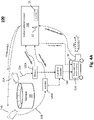
- Fig. 4B illustrates a block diagram of a system for controlling media content capture for live television production according to another exemplary embodiment.
- the exemplary system shown utilizes the low latency streaming technologies to provide a true cloud-based production environment.
- the cloud 160 can be considered Internet-based computing that provides shared computer processing resources and data to computers and other devices on demand.
- the system 200 can utilize public cloud services, such Amazon Web Services (AWS), Microsoft and Google, who own and operate the infrastructure at their data center and providing access to computing resources via the Internet.
- AWS Amazon Web Services
- Azure Microsoft and Google
- the time alignment and processing components 150 can be moved to the cloud computing services to perform the final processing steps for the live video broadcast production.
- the video production can be encoded and transmits by the Internet, for example, to end consumer devices 170, such as computing devices, televisions, set-top boxes, tablets, and the like.
- end consumer devices 170 such as computing devices, televisions, set-top boxes, tablets, and the like.
- This environment can utilize the same fast transfer technology discussed above to transmit the high bandwidth media streams as well, including transmitting the high resolution signals back to the remotely located video control center.
- Fig. 5 illustrates a conceptual flow diagram of a method for bending time of live television production according to an exemplary embodiment. It is noted that the exemplary method can be implemented using the systems described above. Thus, the following description will make reference to the components of the exemplary system.
- cameras e.g., cameras 21A and 21B located at a venue, such as a sports stadium or the like, are configured to capture media content of the live scene in real time.
- the cameras are communicatively coupled to one or a plurality of encoders that receive the media content as data streams and are configured to encode the content and transmit the encoded media streams at step 510 as high speed, low latency proxy streams to a remote control center, for example.
- these low latency proxy streams are received at the control center with very little delay and can be presented on a multi-viewer interface to a technical director or other such user that can make artistic and editorial command decisions that can be transmitted back to the cameras as control decisions.
- the cameras Concurrently (or close to real time), based on the command signals the cameras continue to capture media content, which is processed as a high resolution media signal at step 520 and transmitted to a standard encoder at step 525, which can be located at the venue or at an independent production site, for example.
- the high resolution media signal is provided to a time alignment device at step 530, which also receives control comments from issued by the technical director.
- a time alignment device at step 530, which also receives control comments from issued by the technical director.
- time alignment processing based on PTP and RTP signals, for example, a final production of the broadcast where it is produced and distributed as a live video broadcast at step 535.
- the aspects of the present disclosure are presented with reference to systems and methods used to configure various components of a video production system that may be used for production of television programming or at sports events.
- the various concepts presented throughout this disclosure may be implemented across a broad variety of imaging applications, including systems that capture and process video and/or still images, video conferencing systems and so on. It is understood that the specific order or hierarchy of blocks in the processes/flowcharts disclosed is an illustration of exemplary approaches. Based upon design preferences, it is understood that the specific order or hierarchy of blocks in the processes/flowcharts may be rearranged. Further, some blocks may be combined or omitted.
- the accompanying method claims present elements of the various blocks in a sample order, and are not meant to be limited to the specific order or hierarchy presented.
Landscapes
- Engineering & Computer Science (AREA)
- Multimedia (AREA)
- Signal Processing (AREA)
- Databases & Information Systems (AREA)
- Computer Security & Cryptography (AREA)
- Two-Way Televisions, Distribution Of Moving Picture Or The Like (AREA)
- Studio Circuits (AREA)
- Studio Devices (AREA)
Priority Applications (1)
| Application Number | Priority Date | Filing Date | Title |
|---|---|---|---|
| PL18702247T PL3574654T3 (pl) | 2017-01-27 | 2018-01-27 | System i sposób sterowania przechwytywaniem zawartości medialnej do produkcji transmisji wideo na żywo |
Applications Claiming Priority (3)
| Application Number | Priority Date | Filing Date | Title |
|---|---|---|---|
| US201762451477P | 2017-01-27 | 2017-01-27 | |
| US15/880,988 US10440403B2 (en) | 2017-01-27 | 2018-01-26 | System and method for controlling media content capture for live video broadcast production |
| PCT/EP2018/052023 WO2018138300A1 (en) | 2017-01-27 | 2018-01-27 | System and method for controlling media content capture for live video broadcast production |
Publications (2)
| Publication Number | Publication Date |
|---|---|
| EP3574654A1 EP3574654A1 (en) | 2019-12-04 |
| EP3574654B1 true EP3574654B1 (en) | 2022-05-18 |
Family
ID=61094514
Family Applications (1)
| Application Number | Title | Priority Date | Filing Date |
|---|---|---|---|
| EP18702247.0A Active EP3574654B1 (en) | 2017-01-27 | 2018-01-27 | System and method for controlling media content capture for live video broadcast production |
Country Status (9)
| Country | Link |
|---|---|
| US (4) | US10440403B2 (pl) |
| EP (1) | EP3574654B1 (pl) |
| JP (1) | JP7249946B2 (pl) |
| CN (2) | CN114390298B (pl) |
| AU (1) | AU2018211492A1 (pl) |
| BR (1) | BR112019015465A2 (pl) |
| CA (2) | CA3254521A1 (pl) |
| PL (1) | PL3574654T3 (pl) |
| WO (1) | WO2018138300A1 (pl) |
Families Citing this family (25)
| Publication number | Priority date | Publication date | Assignee | Title |
|---|---|---|---|---|
| US10440403B2 (en) * | 2017-01-27 | 2019-10-08 | Gvbb Holdings S.A.R.L. | System and method for controlling media content capture for live video broadcast production |
| US11303689B2 (en) * | 2017-06-06 | 2022-04-12 | Nokia Technologies Oy | Method and apparatus for updating streamed content |
| US10462203B2 (en) * | 2017-06-13 | 2019-10-29 | Wowza Media Systems, LLC | Hardware encoder |
| US10397518B1 (en) * | 2018-01-16 | 2019-08-27 | Amazon Technologies, Inc. | Combining encoded video streams |
| US11463747B2 (en) | 2018-04-05 | 2022-10-04 | Tvu Networks Corporation | Systems and methods for real time control of a remote video production with multiple streams |
| US10966001B2 (en) | 2018-04-05 | 2021-03-30 | Tvu Networks Corporation | Remote cloud-based video production system in an environment where there is network delay |
| US11470041B2 (en) | 2019-06-20 | 2022-10-11 | Disney Enterprises, Inc. | Software defined network orchestration to manage media flows for broadcast with public cloud networks |
| US10965963B2 (en) | 2019-07-30 | 2021-03-30 | Sling Media Pvt Ltd | Audio-based automatic video feed selection for a digital video production system |
| US11722706B2 (en) * | 2019-12-23 | 2023-08-08 | Dish Network Technologies India Private Limited | Automated optimization of video settings in a digital video production system having multiple video capture devices |
| SE544753C2 (en) * | 2020-01-14 | 2022-11-01 | Net Insight Ab | Network offset adjustment in remote media production |
| US20230063215A1 (en) * | 2020-01-23 | 2023-03-02 | Sony Group Corporation | Information processing apparatus, information processing method, and program |
| KR102922301B1 (ko) * | 2020-04-20 | 2026-02-04 | 사운드하운드, 인코포레이티드 | 미디어 재생 디바이스에서의 콘텐츠 필터링 |
| EP3908006A3 (en) * | 2020-05-01 | 2022-01-26 | TVU Networks Corporation | Systems and methods for real time control of a remote video production with multiple streams |
| IT202000012292A1 (it) * | 2020-05-25 | 2021-11-25 | BLT Italia SRL | Sistema di produzione audiovisiva in remoto |
| CN112333528B (zh) * | 2020-10-24 | 2023-01-10 | 北京华亿创新信息技术股份有限公司 | 一种体育场馆信息发布方法及装置 |
| CN112104894B (zh) * | 2020-11-18 | 2021-03-09 | 成都索贝数码科技股份有限公司 | 一种基于幅面变换的超高清视频编辑方法 |
| US12356053B2 (en) | 2020-12-31 | 2025-07-08 | Koninklijke Kpn N.V. | Multi-view video streaming |
| WO2022144302A1 (en) * | 2020-12-31 | 2022-07-07 | Koninklijke Kpn N.V. | Processing of multi-view video |
| CN113453086A (zh) * | 2021-03-29 | 2021-09-28 | 北京国际云转播科技有限公司 | 多机位同步云导播方法、系统、存储介质和视频编码器 |
| US20240314375A1 (en) * | 2021-07-07 | 2024-09-19 | Nippon Telegraph And Telephone Corporation | Media processing apparatus, media processing method, and media processing program |
| US11849244B2 (en) * | 2021-07-22 | 2023-12-19 | Grass Valley Canada | System and method for temporal keying in a camera |
| CN114500908B (zh) * | 2021-12-31 | 2025-05-09 | 北京三快在线科技有限公司 | 车辆周围环境数据处理方法、系统、装置和车辆 |
| US12401851B1 (en) * | 2022-06-23 | 2025-08-26 | Amazon Technologies, Inc. | Computer-implemented methods for a time synchronized switch across live feeds and channels |
| US20240406503A1 (en) * | 2023-05-30 | 2024-12-05 | Apple Inc. | Presentation Track for Editorial Live Streaming |
| WO2025185825A1 (en) * | 2024-03-07 | 2025-09-12 | Ateliere Creative Technologies Ab | Proxy editing of data streams |
Family Cites Families (29)
| Publication number | Priority date | Publication date | Assignee | Title |
|---|---|---|---|---|
| JP2610227B2 (ja) * | 1994-05-30 | 1997-05-14 | 株式会社ノバックス | 公営競技場の実況中継装置 |
| JP3519191B2 (ja) | 1995-12-15 | 2004-04-12 | 花王株式会社 | 皮膚外用剤 |
| US20020108115A1 (en) * | 2000-12-11 | 2002-08-08 | The Associated Press | News and other information delivery system and method |
| US8063929B2 (en) * | 2007-05-31 | 2011-11-22 | Eastman Kodak Company | Managing scene transitions for video communication |
| US20090089162A1 (en) * | 2007-09-28 | 2009-04-02 | Yahoo!, Inc. | Distributed live multimedia monetization mechanism and network |
| US20090187826A1 (en) * | 2008-01-22 | 2009-07-23 | Reality Check Studios Inc. | Data control and display system |
| WO2010026496A1 (en) * | 2008-09-07 | 2010-03-11 | Sportvu Ltd. | Method and system for fusing video streams |
| US8300114B2 (en) * | 2009-01-30 | 2012-10-30 | Intersil Americas, Inc. | Mixed format media transmission systems and methods |
| US20110202967A1 (en) | 2010-02-12 | 2011-08-18 | Voice The Game, Llc | Apparatus and Method to Broadcast Layered Audio and Video Over Live Streaming Activities |
| US20110205355A1 (en) | 2010-02-19 | 2011-08-25 | Panasonic Corporation | Data Mining Method and System For Estimating Relative 3D Velocity and Acceleration Projection Functions Based on 2D Motions |
| SE535910E (sv) | 2010-11-09 | 2017-09-05 | Twentyfourseven Holding Ab | Videoproduktion via ett fjärrtrafiknät |
| US9357141B2 (en) * | 2011-06-15 | 2016-05-31 | Disney Enterprises, Inc. | Method and apparatus for remotely controlling a live TV production |
| US8515241B2 (en) * | 2011-07-07 | 2013-08-20 | Gannaway Web Holdings, Llc | Real-time video editing |
| CN102340689B (zh) * | 2011-09-20 | 2014-04-30 | 成都索贝数码科技股份有限公司 | 电视台生产系统中业务子系统的配置装置及方法 |
| US9584774B2 (en) * | 2011-10-24 | 2017-02-28 | Motorola Solutions, Inc. | Method and apparatus for remotely controlling an image capture position of a camera |
| WO2013066347A1 (en) * | 2011-11-04 | 2013-05-10 | Russo Paul M | Method and system for remote video monitoring and remote video broadcast |
| US9661047B2 (en) * | 2012-04-30 | 2017-05-23 | Mobilatv Ltd. | Method and system for central utilization of remotely generated large media data streams despite network bandwidth limitations |
| US9497424B2 (en) * | 2012-12-05 | 2016-11-15 | At&T Mobility Ii Llc | System and method for processing streaming media of an event captured by nearby mobile phones |
| US9338480B2 (en) * | 2013-03-01 | 2016-05-10 | Disney Enterprises, Inc. | Systems and methods to compensate for the effects of transmission delay |
| US9318149B2 (en) * | 2013-03-01 | 2016-04-19 | Gvbb Holdings S.A.R.L. | Method and system of composite broadcast control |
| US9681028B2 (en) * | 2013-03-15 | 2017-06-13 | Red.Com, Inc. | Digital camera with wireless connectivity |
| WO2014145925A1 (en) | 2013-03-15 | 2014-09-18 | Moontunes, Inc. | Systems and methods for controlling cameras at live events |
| WO2014168833A1 (en) * | 2013-04-08 | 2014-10-16 | Shafron Thomas | Camera assembly, system, and method for intelligent video capture and streaming |
| CA2949005C (en) * | 2013-05-26 | 2021-06-29 | Pixellot Ltd. | Method and system for low cost television production |
| US20150110166A1 (en) * | 2013-10-23 | 2015-04-23 | Paladin Innovators | Mechanics and Processes for Remote Control of Live Video Production |
| CN105208110B (zh) * | 2015-08-31 | 2019-11-01 | 小米科技有限责任公司 | 资源控制方法及装置 |
| CA3007355C (en) * | 2015-12-04 | 2021-05-04 | Sling Media, Inc. | Network-based event recording |
| CN105828216B (zh) * | 2016-03-31 | 2019-04-26 | 北京奇艺世纪科技有限公司 | 一种直播视频字幕合成系统及方法 |
| US10440403B2 (en) * | 2017-01-27 | 2019-10-08 | Gvbb Holdings S.A.R.L. | System and method for controlling media content capture for live video broadcast production |
-
2018
- 2018-01-26 US US15/880,988 patent/US10440403B2/en active Active
- 2018-01-27 BR BR112019015465-5A patent/BR112019015465A2/pt not_active Application Discontinuation
- 2018-01-27 WO PCT/EP2018/052023 patent/WO2018138300A1/en not_active Ceased
- 2018-01-27 AU AU2018211492A patent/AU2018211492A1/en not_active Abandoned
- 2018-01-27 CN CN202210050465.2A patent/CN114390298B/zh not_active Expired - Fee Related
- 2018-01-27 CA CA3254521A patent/CA3254521A1/en active Pending
- 2018-01-27 EP EP18702247.0A patent/EP3574654B1/en active Active
- 2018-01-27 CA CA3051631A patent/CA3051631C/en active Active
- 2018-01-27 CN CN201880017521.4A patent/CN110402581B/zh not_active Expired - Fee Related
- 2018-01-27 PL PL18702247T patent/PL3574654T3/pl unknown
- 2018-01-27 JP JP2019540522A patent/JP7249946B2/ja active Active
-
2019
- 2019-10-07 US US16/594,942 patent/US10728586B2/en active Active
-
2020
- 2020-07-24 US US16/938,382 patent/US11140423B2/en not_active Expired - Fee Related
-
2021
- 2021-09-30 US US17/449,656 patent/US11695970B2/en active Active
Also Published As
| Publication number | Publication date |
|---|---|
| US10440403B2 (en) | 2019-10-08 |
| US20180220166A1 (en) | 2018-08-02 |
| EP3574654A1 (en) | 2019-12-04 |
| BR112019015465A2 (pt) | 2020-03-31 |
| CN110402581A (zh) | 2019-11-01 |
| CN114390298A (zh) | 2022-04-22 |
| US11140423B2 (en) | 2021-10-05 |
| JP7249946B2 (ja) | 2023-03-31 |
| US10728586B2 (en) | 2020-07-28 |
| CA3254521A1 (en) | 2025-02-25 |
| CA3051631C (en) | 2025-07-22 |
| PL3574654T3 (pl) | 2022-07-04 |
| CN110402581B (zh) | 2022-02-18 |
| US20200359057A1 (en) | 2020-11-12 |
| US11695970B2 (en) | 2023-07-04 |
| CA3051631A1 (en) | 2018-08-02 |
| CN114390298B (zh) | 2023-10-17 |
| WO2018138300A1 (en) | 2018-08-02 |
| US20200145700A1 (en) | 2020-05-07 |
| AU2018211492A1 (en) | 2019-08-22 |
| US20220021909A1 (en) | 2022-01-20 |
| JP2020509646A (ja) | 2020-03-26 |
Similar Documents
| Publication | Publication Date | Title |
|---|---|---|
| US11695970B2 (en) | System and method for controlling media content capture for live video broadcast production | |
| US11201903B1 (en) | Time synchronization between live video streaming and live metadata | |
| US12483612B2 (en) | Immersive viewport dependent multiparty video communication | |
| US9860572B2 (en) | Spatially segmented content delivery | |
| US12108097B2 (en) | Combining video streams in composite video stream with metadata | |
| JP2013516847A (ja) | クライアントデバイスへのマネージドネットワーク上でのテレビ放送およびアンマネージドネットワーク上での双方向コンテンツの提供 | |
| JP2023078280A (ja) | データ・ストリーム変更を制御するシステムおよび方法 | |
| US20210160563A1 (en) | Method and apparatus for preview decoding for joint video production | |
| US20160014417A1 (en) | Methods and apparatuses for stripe-based temporal and spatial video processing | |
| TWI531244B (zh) | 視訊會議資料處理方法及系統 | |
| Lange et al. | A complete multi-view video streaming system |
Legal Events
| Date | Code | Title | Description |
|---|---|---|---|
| STAA | Information on the status of an ep patent application or granted ep patent |
Free format text: STATUS: UNKNOWN |
|
| STAA | Information on the status of an ep patent application or granted ep patent |
Free format text: STATUS: THE INTERNATIONAL PUBLICATION HAS BEEN MADE |
|
| PUAI | Public reference made under article 153(3) epc to a published international application that has entered the european phase |
Free format text: ORIGINAL CODE: 0009012 |
|
| STAA | Information on the status of an ep patent application or granted ep patent |
Free format text: STATUS: REQUEST FOR EXAMINATION WAS MADE |
|
| 17P | Request for examination filed |
Effective date: 20190730 |
|
| AK | Designated contracting states |
Kind code of ref document: A1 Designated state(s): AL AT BE BG CH CY CZ DE DK EE ES FI FR GB GR HR HU IE IS IT LI LT LU LV MC MK MT NL NO PL PT RO RS SE SI SK SM TR |
|
| AX | Request for extension of the european patent |
Extension state: BA ME |
|
| DAV | Request for validation of the european patent (deleted) | ||
| DAX | Request for extension of the european patent (deleted) | ||
| STAA | Information on the status of an ep patent application or granted ep patent |
Free format text: STATUS: EXAMINATION IS IN PROGRESS |
|
| 17Q | First examination report despatched |
Effective date: 20200727 |
|
| GRAP | Despatch of communication of intention to grant a patent |
Free format text: ORIGINAL CODE: EPIDOSNIGR1 |
|
| STAA | Information on the status of an ep patent application or granted ep patent |
Free format text: STATUS: GRANT OF PATENT IS INTENDED |
|
| RIC1 | Information provided on ipc code assigned before grant |
Ipc: H04N 5/268 20060101ALI20220216BHEP Ipc: H04N 5/222 20060101ALI20220216BHEP Ipc: H04N 21/2187 20110101ALI20220216BHEP Ipc: H04N 21/242 20110101ALI20220216BHEP Ipc: H04N 21/2343 20110101AFI20220216BHEP |
|
| GRAS | Grant fee paid |
Free format text: ORIGINAL CODE: EPIDOSNIGR3 |
|
| GRAA | (expected) grant |
Free format text: ORIGINAL CODE: 0009210 |
|
| STAA | Information on the status of an ep patent application or granted ep patent |
Free format text: STATUS: THE PATENT HAS BEEN GRANTED |
|
| INTG | Intention to grant announced |
Effective date: 20220321 |
|
| AK | Designated contracting states |
Kind code of ref document: B1 Designated state(s): AL AT BE BG CH CY CZ DE DK EE ES FI FR GB GR HR HU IE IS IT LI LT LU LV MC MK MT NL NO PL PT RO RS SE SI SK SM TR |
|
| REG | Reference to a national code |
Ref country code: GB Ref legal event code: FG4D |
|
| REG | Reference to a national code |
Ref country code: CH Ref legal event code: EP |
|
| REG | Reference to a national code |
Ref country code: IE Ref legal event code: FG4D |
|
| REG | Reference to a national code |
Ref country code: DE Ref legal event code: R096 Ref document number: 602018035723 Country of ref document: DE |
|
| REG | Reference to a national code |
Ref country code: AT Ref legal event code: REF Ref document number: 1493810 Country of ref document: AT Kind code of ref document: T Effective date: 20220615 |
|
| REG | Reference to a national code |
Ref country code: NL Ref legal event code: FP |
|
| REG | Reference to a national code |
Ref country code: NL Ref legal event code: PD Owner name: GRASS VALLEY CANADA; CA Free format text: DETAILS ASSIGNMENT: CHANGE OF OWNER(S), ASSIGNMENT; FORMER OWNER NAME: GVBB HOLDINGS S.A.R.L Effective date: 20220723 |
|
| RAP2 | Party data changed (patent owner data changed or rights of a patent transferred) |
Owner name: GRASS VALLEY CANADA |
|
| REG | Reference to a national code |
Ref country code: LT Ref legal event code: MG9D |
|
| REG | Reference to a national code |
Ref country code: AT Ref legal event code: MK05 Ref document number: 1493810 Country of ref document: AT Kind code of ref document: T Effective date: 20220518 |
|
| PG25 | Lapsed in a contracting state [announced via postgrant information from national office to epo] |
Ref country code: SE Free format text: LAPSE BECAUSE OF FAILURE TO SUBMIT A TRANSLATION OF THE DESCRIPTION OR TO PAY THE FEE WITHIN THE PRESCRIBED TIME-LIMIT Effective date: 20220518 Ref country code: PT Free format text: LAPSE BECAUSE OF FAILURE TO SUBMIT A TRANSLATION OF THE DESCRIPTION OR TO PAY THE FEE WITHIN THE PRESCRIBED TIME-LIMIT Effective date: 20220919 Ref country code: NO Free format text: LAPSE BECAUSE OF FAILURE TO SUBMIT A TRANSLATION OF THE DESCRIPTION OR TO PAY THE FEE WITHIN THE PRESCRIBED TIME-LIMIT Effective date: 20220818 Ref country code: LT Free format text: LAPSE BECAUSE OF FAILURE TO SUBMIT A TRANSLATION OF THE DESCRIPTION OR TO PAY THE FEE WITHIN THE PRESCRIBED TIME-LIMIT Effective date: 20220518 Ref country code: HR Free format text: LAPSE BECAUSE OF FAILURE TO SUBMIT A TRANSLATION OF THE DESCRIPTION OR TO PAY THE FEE WITHIN THE PRESCRIBED TIME-LIMIT Effective date: 20220518 Ref country code: GR Free format text: LAPSE BECAUSE OF FAILURE TO SUBMIT A TRANSLATION OF THE DESCRIPTION OR TO PAY THE FEE WITHIN THE PRESCRIBED TIME-LIMIT Effective date: 20220819 Ref country code: FI Free format text: LAPSE BECAUSE OF FAILURE TO SUBMIT A TRANSLATION OF THE DESCRIPTION OR TO PAY THE FEE WITHIN THE PRESCRIBED TIME-LIMIT Effective date: 20220518 Ref country code: ES Free format text: LAPSE BECAUSE OF FAILURE TO SUBMIT A TRANSLATION OF THE DESCRIPTION OR TO PAY THE FEE WITHIN THE PRESCRIBED TIME-LIMIT Effective date: 20220518 Ref country code: BG Free format text: LAPSE BECAUSE OF FAILURE TO SUBMIT A TRANSLATION OF THE DESCRIPTION OR TO PAY THE FEE WITHIN THE PRESCRIBED TIME-LIMIT Effective date: 20220818 Ref country code: AT Free format text: LAPSE BECAUSE OF FAILURE TO SUBMIT A TRANSLATION OF THE DESCRIPTION OR TO PAY THE FEE WITHIN THE PRESCRIBED TIME-LIMIT Effective date: 20220518 |
|
| PG25 | Lapsed in a contracting state [announced via postgrant information from national office to epo] |
Ref country code: RS Free format text: LAPSE BECAUSE OF FAILURE TO SUBMIT A TRANSLATION OF THE DESCRIPTION OR TO PAY THE FEE WITHIN THE PRESCRIBED TIME-LIMIT Effective date: 20220518 Ref country code: LV Free format text: LAPSE BECAUSE OF FAILURE TO SUBMIT A TRANSLATION OF THE DESCRIPTION OR TO PAY THE FEE WITHIN THE PRESCRIBED TIME-LIMIT Effective date: 20220518 Ref country code: IS Free format text: LAPSE BECAUSE OF FAILURE TO SUBMIT A TRANSLATION OF THE DESCRIPTION OR TO PAY THE FEE WITHIN THE PRESCRIBED TIME-LIMIT Effective date: 20220918 |
|
| PG25 | Lapsed in a contracting state [announced via postgrant information from national office to epo] |
Ref country code: SM Free format text: LAPSE BECAUSE OF FAILURE TO SUBMIT A TRANSLATION OF THE DESCRIPTION OR TO PAY THE FEE WITHIN THE PRESCRIBED TIME-LIMIT Effective date: 20220518 Ref country code: SK Free format text: LAPSE BECAUSE OF FAILURE TO SUBMIT A TRANSLATION OF THE DESCRIPTION OR TO PAY THE FEE WITHIN THE PRESCRIBED TIME-LIMIT Effective date: 20220518 Ref country code: RO Free format text: LAPSE BECAUSE OF FAILURE TO SUBMIT A TRANSLATION OF THE DESCRIPTION OR TO PAY THE FEE WITHIN THE PRESCRIBED TIME-LIMIT Effective date: 20220518 Ref country code: EE Free format text: LAPSE BECAUSE OF FAILURE TO SUBMIT A TRANSLATION OF THE DESCRIPTION OR TO PAY THE FEE WITHIN THE PRESCRIBED TIME-LIMIT Effective date: 20220518 Ref country code: DK Free format text: LAPSE BECAUSE OF FAILURE TO SUBMIT A TRANSLATION OF THE DESCRIPTION OR TO PAY THE FEE WITHIN THE PRESCRIBED TIME-LIMIT Effective date: 20220518 Ref country code: CZ Free format text: LAPSE BECAUSE OF FAILURE TO SUBMIT A TRANSLATION OF THE DESCRIPTION OR TO PAY THE FEE WITHIN THE PRESCRIBED TIME-LIMIT Effective date: 20220518 |
|
| REG | Reference to a national code |
Ref country code: DE Ref legal event code: R097 Ref document number: 602018035723 Country of ref document: DE |
|
| PLBE | No opposition filed within time limit |
Free format text: ORIGINAL CODE: 0009261 |
|
| STAA | Information on the status of an ep patent application or granted ep patent |
Free format text: STATUS: NO OPPOSITION FILED WITHIN TIME LIMIT |
|
| PG25 | Lapsed in a contracting state [announced via postgrant information from national office to epo] |
Ref country code: AL Free format text: LAPSE BECAUSE OF FAILURE TO SUBMIT A TRANSLATION OF THE DESCRIPTION OR TO PAY THE FEE WITHIN THE PRESCRIBED TIME-LIMIT Effective date: 20220518 |
|
| 26N | No opposition filed |
Effective date: 20230221 |
|
| PG25 | Lapsed in a contracting state [announced via postgrant information from national office to epo] |
Ref country code: SI Free format text: LAPSE BECAUSE OF FAILURE TO SUBMIT A TRANSLATION OF THE DESCRIPTION OR TO PAY THE FEE WITHIN THE PRESCRIBED TIME-LIMIT Effective date: 20220518 |
|
| REG | Reference to a national code |
Ref country code: CH Ref legal event code: PL |
|
| PG25 | Lapsed in a contracting state [announced via postgrant information from national office to epo] |
Ref country code: LU Free format text: LAPSE BECAUSE OF NON-PAYMENT OF DUE FEES Effective date: 20230127 |
|
| REG | Reference to a national code |
Ref country code: BE Ref legal event code: MM Effective date: 20230131 |
|
| PG25 | Lapsed in a contracting state [announced via postgrant information from national office to epo] |
Ref country code: LI Free format text: LAPSE BECAUSE OF NON-PAYMENT OF DUE FEES Effective date: 20230131 Ref country code: CH Free format text: LAPSE BECAUSE OF NON-PAYMENT OF DUE FEES Effective date: 20230131 |
|
| PG25 | Lapsed in a contracting state [announced via postgrant information from national office to epo] |
Ref country code: FR Free format text: LAPSE BECAUSE OF NON-PAYMENT OF DUE FEES Effective date: 20230131 Ref country code: BE Free format text: LAPSE BECAUSE OF NON-PAYMENT OF DUE FEES Effective date: 20230131 |
|
| PG25 | Lapsed in a contracting state [announced via postgrant information from national office to epo] |
Ref country code: IE Free format text: LAPSE BECAUSE OF NON-PAYMENT OF DUE FEES Effective date: 20230127 |
|
| PGFP | Annual fee paid to national office [announced via postgrant information from national office to epo] |
Ref country code: NL Payment date: 20240126 Year of fee payment: 7 |
|
| PGFP | Annual fee paid to national office [announced via postgrant information from national office to epo] |
Ref country code: DE Payment date: 20240129 Year of fee payment: 7 Ref country code: GB Payment date: 20240129 Year of fee payment: 7 |
|
| PGFP | Annual fee paid to national office [announced via postgrant information from national office to epo] |
Ref country code: PL Payment date: 20240103 Year of fee payment: 7 Ref country code: IT Payment date: 20240122 Year of fee payment: 7 |
|
| PG25 | Lapsed in a contracting state [announced via postgrant information from national office to epo] |
Ref country code: MC Free format text: LAPSE BECAUSE OF FAILURE TO SUBMIT A TRANSLATION OF THE DESCRIPTION OR TO PAY THE FEE WITHIN THE PRESCRIBED TIME-LIMIT Effective date: 20220518 |
|
| PG25 | Lapsed in a contracting state [announced via postgrant information from national office to epo] |
Ref country code: MC Free format text: LAPSE BECAUSE OF FAILURE TO SUBMIT A TRANSLATION OF THE DESCRIPTION OR TO PAY THE FEE WITHIN THE PRESCRIBED TIME-LIMIT Effective date: 20220518 |
|
| PG25 | Lapsed in a contracting state [announced via postgrant information from national office to epo] |
Ref country code: BG Free format text: LAPSE BECAUSE OF FAILURE TO SUBMIT A TRANSLATION OF THE DESCRIPTION OR TO PAY THE FEE WITHIN THE PRESCRIBED TIME-LIMIT Effective date: 20220518 |
|
| PG25 | Lapsed in a contracting state [announced via postgrant information from national office to epo] |
Ref country code: BG Free format text: LAPSE BECAUSE OF FAILURE TO SUBMIT A TRANSLATION OF THE DESCRIPTION OR TO PAY THE FEE WITHIN THE PRESCRIBED TIME-LIMIT Effective date: 20220518 |
|
| PG25 | Lapsed in a contracting state [announced via postgrant information from national office to epo] |
Ref country code: CY Free format text: LAPSE BECAUSE OF FAILURE TO SUBMIT A TRANSLATION OF THE DESCRIPTION OR TO PAY THE FEE WITHIN THE PRESCRIBED TIME-LIMIT; INVALID AB INITIO Effective date: 20180127 |
|
| REG | Reference to a national code |
Ref country code: DE Ref legal event code: R119 Ref document number: 602018035723 Country of ref document: DE |
|
| PG25 | Lapsed in a contracting state [announced via postgrant information from national office to epo] |
Ref country code: HU Free format text: LAPSE BECAUSE OF FAILURE TO SUBMIT A TRANSLATION OF THE DESCRIPTION OR TO PAY THE FEE WITHIN THE PRESCRIBED TIME-LIMIT; INVALID AB INITIO Effective date: 20180127 |
|
| REG | Reference to a national code |
Ref country code: NL Ref legal event code: MM Effective date: 20250201 |
|
| GBPC | Gb: european patent ceased through non-payment of renewal fee |
Effective date: 20250127 |
|
| PG25 | Lapsed in a contracting state [announced via postgrant information from national office to epo] |
Ref country code: DE Free format text: LAPSE BECAUSE OF NON-PAYMENT OF DUE FEES Effective date: 20250801 |
|
| PG25 | Lapsed in a contracting state [announced via postgrant information from national office to epo] |
Ref country code: NL Free format text: LAPSE BECAUSE OF NON-PAYMENT OF DUE FEES Effective date: 20250201 |
|
| PG25 | Lapsed in a contracting state [announced via postgrant information from national office to epo] |
Ref country code: GB Free format text: LAPSE BECAUSE OF NON-PAYMENT OF DUE FEES Effective date: 20250127 |
|
| PG25 | Lapsed in a contracting state [announced via postgrant information from national office to epo] |
Ref country code: TR Free format text: LAPSE BECAUSE OF FAILURE TO SUBMIT A TRANSLATION OF THE DESCRIPTION OR TO PAY THE FEE WITHIN THE PRESCRIBED TIME-LIMIT Effective date: 20220518 |
|
| PG25 | Lapsed in a contracting state [announced via postgrant information from national office to epo] |
Ref country code: IT Free format text: LAPSE BECAUSE OF NON-PAYMENT OF DUE FEES Effective date: 20250127 |