EP3574261B1 - Boilereinheit - Google Patents
Boilereinheit Download PDFInfo
- Publication number
- EP3574261B1 EP3574261B1 EP18702535.8A EP18702535A EP3574261B1 EP 3574261 B1 EP3574261 B1 EP 3574261B1 EP 18702535 A EP18702535 A EP 18702535A EP 3574261 B1 EP3574261 B1 EP 3574261B1
- Authority
- EP
- European Patent Office
- Prior art keywords
- chamber
- gas cleaning
- heat exchange
- integrated unit
- gases
- Prior art date
- Legal status (The legal status is an assumption and is not a legal conclusion. Google has not performed a legal analysis and makes no representation as to the accuracy of the status listed.)
- Active
Links
Images


Classifications
-
- F—MECHANICAL ENGINEERING; LIGHTING; HEATING; WEAPONS; BLASTING
- F23—COMBUSTION APPARATUS; COMBUSTION PROCESSES
- F23G—CREMATION FURNACES; CONSUMING WASTE PRODUCTS BY COMBUSTION
- F23G5/00—Incineration of waste; Incinerator constructions; Details, accessories or control therefor
- F23G5/02—Incineration of waste; Incinerator constructions; Details, accessories or control therefor with pretreatment
- F23G5/027—Incineration of waste; Incinerator constructions; Details, accessories or control therefor with pretreatment pyrolising or gasifying stage
- F23G5/0276—Incineration of waste; Incinerator constructions; Details, accessories or control therefor with pretreatment pyrolising or gasifying stage using direct heating
-
- F—MECHANICAL ENGINEERING; LIGHTING; HEATING; WEAPONS; BLASTING
- F23—COMBUSTION APPARATUS; COMBUSTION PROCESSES
- F23J—REMOVAL OR TREATMENT OF COMBUSTION PRODUCTS OR COMBUSTION RESIDUES; FLUES
- F23J15/00—Arrangements of devices for treating smoke or fumes
- F23J15/02—Arrangements of devices for treating smoke or fumes of purifiers, e.g. for removing noxious material
-
- C—CHEMISTRY; METALLURGY
- C10—PETROLEUM, GAS OR COKE INDUSTRIES; TECHNICAL GASES CONTAINING CARBON MONOXIDE; FUELS; LUBRICANTS; PEAT
- C10J—PRODUCTION OF PRODUCER GAS, WATER-GAS, SYNTHESIS GAS FROM SOLID CARBONACEOUS MATERIAL, OR MIXTURES CONTAINING THESE GASES; CARBURETTING AIR OR OTHER GASES
- C10J3/00—Production of combustible gases containing carbon monoxide from solid carbonaceous fuels
- C10J3/46—Gasification of granular or pulverulent flues in suspension
- C10J3/48—Apparatus; Plants
- C10J3/52—Ash-removing devices
-
- C—CHEMISTRY; METALLURGY
- C10—PETROLEUM, GAS OR COKE INDUSTRIES; TECHNICAL GASES CONTAINING CARBON MONOXIDE; FUELS; LUBRICANTS; PEAT
- C10J—PRODUCTION OF PRODUCER GAS, WATER-GAS, SYNTHESIS GAS FROM SOLID CARBONACEOUS MATERIAL, OR MIXTURES CONTAINING THESE GASES; CARBURETTING AIR OR OTHER GASES
- C10J3/00—Production of combustible gases containing carbon monoxide from solid carbonaceous fuels
- C10J3/72—Other features
- C10J3/82—Gas withdrawal means
- C10J3/84—Gas withdrawal means with means for removing dust or tar from the gas
-
- F—MECHANICAL ENGINEERING; LIGHTING; HEATING; WEAPONS; BLASTING
- F23—COMBUSTION APPARATUS; COMBUSTION PROCESSES
- F23C—METHODS OR APPARATUS FOR COMBUSTION USING FLUID FUEL OR SOLID FUEL SUSPENDED IN A CARRIER GAS OR AIR
- F23C10/00—Fluidised bed combustion apparatus
- F23C10/002—Fluidised bed combustion apparatus for pulverulent solid fuel
-
- F—MECHANICAL ENGINEERING; LIGHTING; HEATING; WEAPONS; BLASTING
- F23—COMBUSTION APPARATUS; COMBUSTION PROCESSES
- F23G—CREMATION FURNACES; CONSUMING WASTE PRODUCTS BY COMBUSTION
- F23G5/00—Incineration of waste; Incinerator constructions; Details, accessories or control therefor
- F23G5/30—Incineration of waste; Incinerator constructions; Details, accessories or control therefor having a fluidised bed
-
- F—MECHANICAL ENGINEERING; LIGHTING; HEATING; WEAPONS; BLASTING
- F23—COMBUSTION APPARATUS; COMBUSTION PROCESSES
- F23G—CREMATION FURNACES; CONSUMING WASTE PRODUCTS BY COMBUSTION
- F23G5/00—Incineration of waste; Incinerator constructions; Details, accessories or control therefor
- F23G5/44—Details; Accessories
- F23G5/46—Recuperation of heat
-
- F—MECHANICAL ENGINEERING; LIGHTING; HEATING; WEAPONS; BLASTING
- F23—COMBUSTION APPARATUS; COMBUSTION PROCESSES
- F23G—CREMATION FURNACES; CONSUMING WASTE PRODUCTS BY COMBUSTION
- F23G7/00—Incinerators or other apparatus for consuming industrial waste, e.g. chemicals
- F23G7/10—Incinerators or other apparatus for consuming industrial waste, e.g. chemicals of field or garden waste or biomasses
-
- F—MECHANICAL ENGINEERING; LIGHTING; HEATING; WEAPONS; BLASTING
- F23—COMBUSTION APPARATUS; COMBUSTION PROCESSES
- F23J—REMOVAL OR TREATMENT OF COMBUSTION PRODUCTS OR COMBUSTION RESIDUES; FLUES
- F23J15/00—Arrangements of devices for treating smoke or fumes
- F23J15/02—Arrangements of devices for treating smoke or fumes of purifiers, e.g. for removing noxious material
- F23J15/022—Arrangements of devices for treating smoke or fumes of purifiers, e.g. for removing noxious material for removing solid particulate material from the gasflow
- F23J15/025—Arrangements of devices for treating smoke or fumes of purifiers, e.g. for removing noxious material for removing solid particulate material from the gasflow using filters
-
- C—CHEMISTRY; METALLURGY
- C10—PETROLEUM, GAS OR COKE INDUSTRIES; TECHNICAL GASES CONTAINING CARBON MONOXIDE; FUELS; LUBRICANTS; PEAT
- C10J—PRODUCTION OF PRODUCER GAS, WATER-GAS, SYNTHESIS GAS FROM SOLID CARBONACEOUS MATERIAL, OR MIXTURES CONTAINING THESE GASES; CARBURETTING AIR OR OTHER GASES
- C10J2300/00—Details of gasification processes
- C10J2300/16—Integration of gasification processes with another plant or parts within the plant
- C10J2300/1625—Integration of gasification processes with another plant or parts within the plant with solids treatment
- C10J2300/1628—Ash post-treatment
-
- F—MECHANICAL ENGINEERING; LIGHTING; HEATING; WEAPONS; BLASTING
- F23—COMBUSTION APPARATUS; COMBUSTION PROCESSES
- F23G—CREMATION FURNACES; CONSUMING WASTE PRODUCTS BY COMBUSTION
- F23G2201/00—Pretreatment
- F23G2201/30—Pyrolysing
- F23G2201/301—Treating pyrogases
-
- F—MECHANICAL ENGINEERING; LIGHTING; HEATING; WEAPONS; BLASTING
- F23—COMBUSTION APPARATUS; COMBUSTION PROCESSES
- F23G—CREMATION FURNACES; CONSUMING WASTE PRODUCTS BY COMBUSTION
- F23G2201/00—Pretreatment
- F23G2201/40—Gasification
-
- F—MECHANICAL ENGINEERING; LIGHTING; HEATING; WEAPONS; BLASTING
- F23—COMBUSTION APPARATUS; COMBUSTION PROCESSES
- F23J—REMOVAL OR TREATMENT OF COMBUSTION PRODUCTS OR COMBUSTION RESIDUES; FLUES
- F23J2217/00—Intercepting solids
- F23J2217/10—Intercepting solids by filters
- F23J2217/101—Baghouse type
Definitions
- This invention relates to a solid fuel fired boiler unit including gasifiers and pyrolisers, and methods and apparatus for cooling and cleaning gas from such units.
- the method and apparatus can be used in combination with a fluid bed boiler or in combination with a grate style combustion unit or any other solid fuel fired boiler combustion, gasification or pyrolising system.
- Boiler, gasifier and pyrolising units such as fluid beds are well known.
- a fluid bed boiler is provided, the fluid bed boiler having a combustion, gasification or pyrolising chamber and fuel is fed to that chamber.
- Waste gases or syngas pass from the chamber to a radiant chamber then pass to a convector section or chamber to cool the gases.
- Gases exiting the chamber are typically transferred to a separate cleaner unit.
- Sorbent is injected into the gas flow prior to entry to the cleaner unit.
- the cleaner unit typically comprises a bag filter and a baffle system arranged to direct flow of the waste gases into the bag filters. On exit from the cleaning unit gases are transferred by pipes to a chimney.
- FR2310530 discloses apparatus for using exhaust heat from burning refuse is described wherein a heat exchanger constructed as a self-supporting unit is mounted, inside an enclosure, directly on the combustion chamber.
- the heat exchanger consists of at least two co-axial, vertical, cylindrical, single-layer packs of helical tubes with their convolutions in close contact with one another and located so that they lie nearly perpendicular to the direction of flow of the smoke and gases of combustion.
- One or each of the packs consists of a plurality of tubes with the convolutions of the respective tubes arranged in repeated series along the length of the pack.
- the packs of helical tubes may be connected in series or in parallel for heating water.
- the sections may be divided individually into sections for any one of a number of alternative boiler configurations in which the sections can provide preheaters, evaporators and superheaters.
- the hot smoke and gases passes upwards inside the innermost pack heating it by radiant heat, is deflected through 180 DEG to pass downwards between that pack and the next one to be deflected again at the bottom through 180 DEG to pass upwards past the said next one and any outer pack to surrender further heat by radiation before being discharged from the enclosure.
- FR1276975 discloses improvements in combustion stoves arranged to have a hearth or the like heating a boiler.
- the hearth is formed as a truncated cone with a vertical axis diverging upwards, the angle of the wall with the vertical being around 15° and the voluime of the truncated cone being substantially equal, to within 2%, to that of the corresponding cone.
- the invention essentially consists in the pooling of the surfaces of the boiler and of the hearth, that is to say the frustoconical surface characteristic of this type of hearth is constituted by a part of the heating surface of the boiler.
- US4974411 discloses a gas and steam turbine power plant having a gas turbine with a gas side, a waste heat steam generator having a steam side and being connected downstream of the gas side of the gas turbine, and a steam turbine connected to the steam side of the waste heat steam generator.
- a super-charged, coal-fired steam generator has an exhaust gas vent line connected to the gas turbine.
- the coal-fired steam generator includes at least one sub stoichiometrically operated fluidized bed furnace system, an integrated dust separator connected downstream of the at least one fluidized bed furnace system, and a steam generator slag tap or wet tap furnace having burners with a gas side connected downstream of the dust separator.
- the boiler is a fluid bed boiler.
- the boiler may be a combustion grate boiler, gasifier or pyroliser.
- the boiler may comprise a combustion fluid bed boiler.
- the boiler may comprise a pyrolysis boiler or a gasification boiler.
- a radiant zone and a convection zone are provided within the integrated unit in fluid communication with gas cleaning apparatus within the integrated unit.
- the radiant zone may be a radiant chamber.
- the convection zone may be a convection chamber.
- the convection chamber is contiguous with the radiant chamber.
- each section of plant fluid bed boiler comprising a radiation chamber and a convection chamber, sorbent injector, gas cleaner comprising a filter chamber, and coolant chimney have been separately designed and built.
- Each section is the responsibility of a separate supplier and the gases are transferred from one section to the next by pipework.
- Such an arrangement lacks cohesiveness and prevents achievement of a compact and efficient design.
- the inventor has realised that designing an integrated unit combining and integrating a boiler unit and gas cleaning apparatus can lead to significant improvements in design and to a compact integrated unit that provides all the functions previously supplied by a number of separate components.
- the integrated unit comprising a unitary boiler and gas cleaning apparatus provides a single component instead of several separate components and transfer of the gases from one section to another is made efficiently and within a compact footprint. Further advantages and improvements are described below.
- the integrated unit and improved design provides an advantageous layout and increases the efficiency of extraction of heat energy and reuse of the heat energy in the system or to generate heat energy. Further the integrated unit can be installed on the power generation site as a single unit with a compact footprint, so providing significant advantages over the existing multi-section systems.
- the boiler comprises a reaction unit comprising a chamber in which combustion, gasification or pyrolysis occurs.
- the reaction unit comprises a combustion zone which may in come embodiments comprise a fluid bed burner, which will be described in more detail below.
- the fluid bed is arranged to combust or gasify solid fuels such as landfill waste, biomass or coal.
- the reaction unit is connected to a radiant zone which desirably is in the form of a radiant chamber.
- the radiant zone is positioned above the reaction unit.
- gases can flow freely from a combustion zone of the reaction unit to the radiant zone.
- the radiant zone comprises a radiant chamber acting as a cold black body and absorbing heat from the reaction unit into the boiler fluid.
- the radiant chamber is preferably arranged to facilitate maintenance of a temperature of the reaction unit at a desired temperature or in a desired temperature range.
- the radiant chamber facilitates maintenance of the temperature in the fluid bed in a desired temperature range by extracting heat into the boiler fluid.
- the temperature in the fluid bed is held between 600°C and 1200°C and more preferably between 700°C and 1100°C and most preferably between 800°C and 1000°C.
- the temperature in the radiant chamber is between 800° C and 1000°C.
- gases passing from the fluid bed are resident in the radiant chamber for a period of time.
- the gases may be resident in the radiant chamber for between 0.5 seconds and 5 seconds or between 1 and 4 seconds.
- the gases are resident in the radiant chamber for at least 1 to 3 seconds.
- the gases are held at a temperature of at least 850°C for at least 2 seconds following injection of secondary combustion air.
- a portion of the time at a temperature of greater than 850° C may be in the fluid bed and a portion of the time may be in the radiant chamber.
- the gases are held at a temperature of greater than 850C for a period of time long enough to combust products such as hydrocarbons, dioxin and furans. Desirably the period of time is sufficient to comply with legal requirements.
- the system complies with current legal requirements on treatment of waste and so may ensure that waste products are fully combusted such that hydrocarbons, dioxins and furans are destroyed.
- the radiant zone is fluidly connected to the convection zone. Desirably the radiant chamber is located above the reaction unit. Preferably the convection zone is fluidly connected to the radiant zone and is desirably distal from the reaction unit. The radiant zone and the convection zone may be freely connected.
- the convection zone comprises a convection chamber.
- the radiant zone and the convection zone may be regarded as separate zones of a single chamber. The skilled person will appreciate that the radiant zone and the convention zone have separate functions that will be well known to and understood by the person skilled in the art.
- the radiant chamber comprises a chamber surrounded by a heat exchange means.
- the heat exchange means may comprise a helically wound heat exchange coil.
- the convection chamber comprises a chamber surrounded by a heat exchange means.
- the heat exchange means comprises a helically wound heat exchange coil.
- the heat exchange coil which extends around the convection chamber may be fluidly connected to or continuous with the heat exchange coil surrounding the radiant chamber.
- Gases flowing from the fluid bed and into the radiant chamber flow on to the convection chamber and a directing means diverts the flow of the gases to flow through the or each heat exchange means surrounding the convection chamber and the radiant chamber.
- the heat exchange means is provided in an annular heat exchange chamber which surrounds the radiant and the convection chambers.
- a direction of flow of the gases through the heat exchange chamber is substantially downward and substantially parallel to a direction of flow of the gases from the fluid bed to the radiant chamber and the convection chamber.
- the gas cleaning means is provided around at least part of the heat exchange means.
- the gas cleaning means is provided in an annular gas cleaning chamber surrounding the heat exchange chamber. Desirably gases flowing from the heat exchange chamber are directed to flow around a U-turn and into the gas cleaning chamber such that the gases preferably flow upwardly through the gas cleaning chamber parallel to gases flowing downwardly through the heat exchange chamber.
- sorbents may be injected into the gas flow as the gases exit from the heat exchanger chamber and are directed into the gas cleaning means in the gas cleaning chamber.
- the gas cleaning means comprises a number of bag filters arranged in the gas cleaning chamber.
- the bag filters are arranged in groups around the annular chamber.
- a number of bag filters may be provided in or along a notional radially extending line which may be considered to be extending from a centre of the convection chamber.
- Further bag filters may be arranged along additional radially extending lines such that a segment of an arc around the gas cleaning chamber may contain a number of bag filters spaced regularly around an arc of the gas cleaning chamber.
- the gas cleaning chamber comprises a number of sub-chambers. Each sub-chamber may comprise an arc of the annular chamber.
- bag filters are provided in each sub-chamber.
- one or more sub-chambers may not have bag filters.
- each sub-chamber is provided with a gas flow control means.
- the gas flow control means is provided downstream of the bag filters.
- the gas flow control means may comprise a baffle or alternatively a valve.
- each bag filter comprises a fabric filter fitted around a metal support and arranged to hang within the annular gas cleaning chamber.
- Suitable bag cleaning filters are well known in the art.
- the bag filter may be formed from a ceramic material or a metallic materiel for use with higher temperature gases.
- the bag filter may comprise a metal material.
- the metal material may be in the form of a metal fibre or thread coiled in a random manner.
- the metal support may be arranged downstream of the filter material in order to prevent the fabric filter from collapsing.
- the metal support may be formed from stainless steel.
- the fabric filters are arranged to remove particulate material from the gases.
- the particulate material may be ash.
- the particulate material may comprise other solid materials.
- the filters are arranged to remove any particulate material having a diameter above 0.1 microns.
- sorbents typically in powder form, are injected into the gas flow and desirably the sorbents react with components within the gases to remove sulphur, chlorine and other pollutants from the gas flow.
- Sorbents typically form compounds with the sulphur, chlorine etc. and these solid components are then collected by the bag filters as the gases pass through the filters.
- the sorbents may be any suitable sorbent. Typically the sorbent may be one of sodium bicarbonate, activated carbon, or lime. Other suitable sorbents may be used as is well known to the person skilled in the art.
- the bag filters preferably also remove dust and any other particulate material from the gasses as they pass through the bag filter. There may be a significant amount of particulate material in the gases when the fuel is biomass or landfill waste. The particulate material may typically be ash.
- the sorbent material is drawn towards the bag filters.
- the sorbent material may react with pollutants in the gases prior to reaching the bag filters.
- the sorbent material can desirably collect on the filter material of the bag filters and that the gases can be drawn through the sorbent material and then through the bag filter before passing downstream towards a cooling chimney. It has therefore been appreciated that an increased flow of gases through the sorbent material may increase the amount of sorbent material that is able to react with the pollutants in the gases and desirably locks more pollutants into a solid compound that preferably is not able to pass through the filter material.
- the arrangement of the heat exchange chamber and the gas cleaning chamber are particularly advantageous.
- the heat exchange chamber is arranged as an annular chamber around the radiant and/or convection chamber or chambers.
- the gas cleaning means is provided in an annular gas cleaning chamber.
- the gas cleaning chamber surrounds the heat exchange chamber.
- the gases exiting from the heat exchange chamber may be directed by the U turn at the bottom of the heat exchange chamber such that they may flow upwardly around the annular chamber and the direction of flow is desirably arranged to be directly towards the bag filters.
- the sorbent material may be directed toward the flow of gases and towards the bag filters such that the sorbent material may be held in the direct path of the gases, in contrast to existing gas cleaning units in which sorbent material tends to fall to the floor of the filter unit due to the complex gas flow path.
- particulate material may build up on the upstream side of the bag filters.
- This particulate material may be removed from the bag filters using a pulse of compressed air applied to a downstream side of the bag filter and which passes through the bag filter.
- the compressed air may be arranged to push the bag filter in a reverse direction and force the particulate material off the filter material of the bag filter.
- the particulate material preferably falls from the bag filters to a floor of the gas cleaning chamber and desirably collects at a base of the gas cleaning chamber.
- a means for removing the particulate material may be provided and will be described in more detail below.
- the means for removing the particulate material may comprise a moving floor as will be further described in more detail.
- the described removal means overcomes a particular difficulty with removing particulate material from an annular floor of the chamber.
- Traditional gas cleaning chambers typically utilise an Archimedes screw arrangement to remove waste particulate material from a hopper and it will be appreciated that such an arrangement cannot be used in an annular chamber.
- a downstream side of each of the bag filters is preferably connected to an air pressure source which can be arranged to supply pulse air jets to one or more of the bag filters.
- a suitable solenoid valve and air supply is preferably provided downstream from the bag filters.
- the solenoid valve and air supply is desirably controlled by control means which may be connected to a central control means.
- the bag filters may be cleaned in response to a cleaning schedule or in response to signals from a flow meter.
- bag filters are arranged in groups within the or each sub chamber forming an arc of the gas cleaning chamber.
- the valve or baffle or other flow control means may be provided downstream of the or each sub-chamber.
- pulse air may be provided to a group of bag filters within each sub-chamber of the gas cleaning chamber.
- pulse air may be supplied to a group of 1 to 50 bag filters, or from 2 to 40 bag filters, or from 5 to 20 or most preferably from 8 to 16 bag filters.
- the group of bag filters to which air is supplied may be arranged in a radial line or may comprise a number of radial lines such that a portion of an arc is cleaned at a time.
- the pulsed air may be supplied to all bag filters in a sub-chamber.
- the flow control means may be closed before pulse air is supplied to the bag filters.
- the flow control means may be closed before pulse air is supplied to the bag filters.
- the flow control means is closed cooled exhaust air flows through the remaining sub-chambers in gas cleaning chambers.
- the flow of gas is diverted away from the closed sub-chamber.
- the pulsed air applied to the bag filters dislodges the particulate material which readily falls to the moving floor.
- Gases which pass through the bag filters in normal operation may be deflected and directed to a central outlet point.
- An induced draught fan is preferably provided in the outlet.
- the induced draught fan is preferably arranged to draw gases through the bag filters.
- Desirably the induced draught fan also controls flow of the gases through the outlet and into a chimney.
- the chimney is mounted directly above the integrated unit.
- the chimney extends centrally above the outlet. It will be appreciated that the overall footprint of the boiler, cleaner and chimney is greatly reduced compared to the existing designs. Furthermore, the flow of gases is controlled within the unit and it is not necessary to transport the gases from one section to another. Extraction of heat energy from the system will be further described in more detail below.
- the exhaust gas is arranged to flow through a measuring device.
- the outlet directs the exhaust gas flows through a duct and to a measuring device.
- the measuring device may be used to measure species in the exhaust gases. Regulations relating to pollution control specify limits to pollution species such as chlorides, hydrochlorides, sulphides, sulphur dioxides; nitrogen oxides and particulate material. Other species may also be monitored.
- Testing methods specify that gases should flow a certain distance along a linear path before entering the measuring device. Exhaust gases may enter a chimney or vent that is laterally located or exhaust gases may be returned to a central chimney.
- particulate material from the upstream side of the bag can be removed from the filter and deposited on the floor of the gas cleaning chamber. Over a period of time particulate material may collect on the floor of the gas cleaning chamber and it would be desirable to remove the particulate material from the gas cleaning chamber.
- Preferably at least a portion of the floor is arranged to be rotatable. In some embodiments at least a portion of the floor may be arranged to be openable. In a preferred embodiment a rotatable floor is provided which transports particular material to the openable section of the floor.
- Particulate material can preferably be removed from the floor of the gas cleaning chamber by passing through the openable section of the floor and into a waste hopper. Desirably when the waste hopper is full the waste material can be transported away from the gas cleaning chamber. Typically the waste material may go to landfill.
- the rotatable floor of the gas cleaning chamber may comprise a radial conveyor.
- the radial conveyor may comprise an inner steel plate and an outer steel plate with spacing plates arranged therebetween.
- a device may be provided to rotate one or more spacing plates at a specified location so allowing particulate material to fall into a waste hopper.
- a suitable device for rotating the spacing plate back into position is preferably also provided.
- a single discharge point is provided but it will be appreciated that multiple discharge point could also be utilised.
- the openable section of the floor is arranged to be held in an open position.
- the inner and outer steel plates may be arranged to rotate.
- Paddles may be provided arranged between the inner and outer steel plates. Desirably the paddles are adapted to move particulate material around the rotatable floor and towards opening.
- the reaction unit preferably comprises a fluid bed.
- the bed may typically be formed of sand or malachite and high pressure air may be supplied through sparge tube tubes or nozzles in order to fluidise the bed.
- Recycled flue gas may be used to support fluidisation of the bed.
- Recycled flue gas may provide a limited supply of oxygen for combustion but may be advantageous in controlling the temperature of the fluid bed by controlling a rate of combustion occurring in the fluid bed by controlling the an amount of oxygen present in the fluid bed.
- the fluid bed reactor uses a solid fuel.
- Solid fuel may enter the combustion zone of the reaction unit through a feed chute.
- the fuel may typically be a biomass fuel, waste material or may be coal. Other solid fuels may be used as well or instead of biomass fuels and waste material.
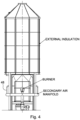
- Combustion is typically in two stages and secondary air may be supplied through a secondary air manifold at an intermediate part of the reaction unit.
- the secondary air supply may be controlled to provide a desirable mixture of gases and in particular a desirable mix of oxygen within the gas in order to provide complete combustion.
- a start-up burner is preferably also provided to initiate combustion. Typically, on initiation of the start-up burner, the bed will achieve a temperature of around 600°C. Once fuel is fed into the bed a working temperature of 800° C may be achieved. It will be appreciated that other temperature ranges may be used for specific fuels or generated by specific fuels.
- the fuel has a residence time of at least 2 seconds at approximately 800 - 850°C after introduction of the secondary air for complete combustion.
- This residence time is specified under current standards in order to ensure that pollutants are fully combusted and removed from the waste gases.
- pollutants might comprise hydrocarbons, dioxins and furans.
- the residence time may be partially within the reaction unit and partially within the radiant zone as discussed above.
- the solid fuels may typically comprise a solid material and that the fuel may be contaminated with other components such as stones, or tramp metal. Contaminants may comprise a material that typically does not burn.
- the reaction unit is desirably arranged such that contaminants will fall into the fluidised bed and that they will gradually drop to the bottom of the fluidised bed. It will be appreciated that over time a build-up of such contaminants in the fluidised bed will prevent fluidising of the bed. Desirably therefore the boiler is arranged to allow ash drawdown periodically which will remove the contaminant material with the ash. In some arrangements an ash drawdown may be carried out on each shift or once a day.
- fuel may be fed to the reaction unit at a rate of approximately from 1 to 20 tonnes of fuel per hour.
- the boiler may be configured to operate without complete combustion and to operate under pyrolytic conditions.
- the boiler may be configured to operate in conditions of incomplete combustion such that the boiler operates as a gasifier.
- the gasifier may be arranged to produce synthetic gas.
- the synthetic gas may be used as a fuel gas for a gas turbine.
- the radiant and the convection chambers are located above the fluidised bed burner. In a particularly preferred embodiment the radiant and the convection chambers extend axially from the fluidised bed burner. In one embodiment the radiant and the convection chambers are defined by helically wound heat exchange tubes. Desirably the heat exchange tubes are water filled. Preferably water flowing in the heat exchange tubes is preheated to a temperature ranging from 100°C to 530°C or more preferably from 150°C to 300°C or most preferably from 180°C to 270°C. Desirably water flowing in the heat exchange tubes is also pressurised to a pressure of from 1 to 150 bargauge or more preferably from 1 to 90 bargauge or most preferably from 5 to 70 bargauge.
- an upper portion of the radiant chamber merges with the convection chamber.
- an upper part of the convection chamber extends to a ducting extending over the axially extending radiant and convection chambers and the ducting preferably directs gases from the convection chamber towards the heat exchange chamber.
- the heat exchange chamber is provided as an annular chamber extending around the axially extending radiant and convection chambers.
- An inner side of the heat exchange chamber is defined by the heat exchange tubes which extend around the radiant and convection chambers and an outer side of the annular heat exchange chamber is preferably defined by a second helically wound heat exchange tube.
- the heat exchange chamber further includes an evaporator comprising a series of heat exchange tubes extending circumferentially around and within the heat exchange chamber.
- the heat exchange chamber further comprises an economiser comprising a further set of heat exchange tubes which extend circumferentially around and within the annular chamber.
- Water from the heat exchanger may be used to provide hot water to heating systems.
- the hot water may be used domestic or industrial or commercial premises.
- the heat exchanger may be arranged to produce process steam.
- Process steam may be used as an energy source in other industrial processes.
- superheated steam may be generated which may be used to generate power.
- the heat exchange chamber extends annually around the convection chambers and the radiant heat chamber and gases travel axially upwards through the radiant chamber and then travel downwardly through the convective heat exchange chamber.
- gases travel axially upwards through the radiant chamber and then travel downwardly through the convective heat exchange chamber.
- gases reach the bottom of the heat exchange chamber they are deflected by a flow reverser formed by a base section or U section and the direction of travel is reversed so that the gases flow upwardly uniformly from the base section and flow directly towards the bag filters.
- Desirably sorbent is injected into the gas flow in a zone close to the flow reverser.
- a method of cleaning gas from a boiler comprises the steps of passing heated gases from the boiler to a convection chamber and a radiation chamber provided above the boiler; providing a heat exchange chamber arranged around and encircling at least one of the radiation chamber and convection chamber and gas cleaning means being provided around at least a part of the heat exchange means.
- the gas cleaning apparatus may further comprise a moving floor.
- the moving floor is rotatable. Desirably at least a portion of the floor is openable.
- the moving floor may comprise a radial conveyor.
- the rotating floor comprises an inner steel plate and an outer steel plate. Spacing plates may be arranged therebetween. Desirably one or more spacing plates are provided between the inner plate and the outer plate. In a preferred embodiment at least one spacing plate is arranged to be openable, preferably by rotating. In some embodiments one openable section is provided. In other embodiments a plurality of openable sections are provided.
- the moving floor comprises a rotating floor having at least one paddle extending between an inner band and an outer band and wherein the or each paddle is arranged to move waste particulate towards an open section.
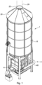
- FIG. 1 is a perspective view of an integrated unit 1 comprising a boiler unit 2 and gas cleaning apparatus in accordance with the present invention.
- the boiler unit 2 comprises a fluid bed boiler 4 providing a reaction unit having a combustion zone 6.
- a cylindrical assemblage 8 is provided above the fluid bed boiler and contains therein a radiant zone 10 and a convection zone 12 encircled by a heat exchange means 14.
- a gas cleaning means 16 is provided around the heat exchange means 14 and the whole assemblage is contained within a cylindrical shell 18.
- An upper portion 20 of the shell tapers inwardly to an outlet 22 which in use is connected to a chimney 24.
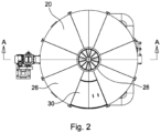
- FIG. 2 A plan view of the integrated unit is shown in Figure 2 .
- the upper portion 20 of the shell can be seen to be divided into segments 26.
- the outlet 28 from the upper portion is located over the radiation and convection chambers. Gases flowing into the upper portion of the shell flow out of the outlet 22 into the chimney 24. A substantially even radial distribution of gases flows into the chimney.
- An access door 30 is also provided in the upper section of the shell.
- the integrated unit has a base 32 comprising a fluid bed boiler.
- the fluid bed comprises a number of sparge tubes 34 which are provided a bed of sand 36.
- a primary air fan is connected to the sparge tubes.
- the sparge tubes 36 are arranged to be spaced across the fluidised bed and run substantially parallel to one another.
- a waste outlet 38 is provided at the bottom of the fluidised bed to allow ash and other waste products to be removed from the fluidised bed periodically.
- a waste hopper 40 or other means of removing waste material is provided below the waste outlet. Waste is removed from the fluidised bed periodically.
- the frequency of removal is typically once a shift or once a day. The frequency may be varied according to the quantity of fuel used and the quality of fuel used.
- a burner 42 is provided for initiation of combustion.
- combustion may be initiated at approximately 600° C and a working temperature of around 800°C to 900C may be achieved.
- a feed chute 44 is provided which delivers fuel material to the fluidised bed.
- the fuel material may be waste material such as landfill or may be a biomass.
- Alternative fuels may be used such as, for example, coal.
- the fuel material is delivered to the fluid bed burner from an outlet 46 above the fluid bed. Fuel falls from the feed chute towards the fluidised bed. Typically around 40% combustion of fuel occurs in the fluidised bed. Pollutants such as tramp metal or inert material that are not combusted fall through the fluidised bed and can be removed from the waste outlet as described above.
- Secondary air is delivered to the combustion zone of the reaction unit by means of an air supply connected to a manifold 48.
- the manifold 48 delivers air to a mid-to upper portion 50 of the combustion zone.
- the air may comprise a mixture of oxygen and other gases.
- a composition of the air may be controlled so that the supply of oxygen in the air is optimised such that substantially complete combustion of fuel can occur in the combustion zone. Typically up to 60% of the combustion can occur around the manifold outlets.
- the temperature in the upper portion of the combustion zone can reach between 1200°C and 1300°C. As described below this temperature may be controlled in use to be lower than 1200°C.
- the temperature in the upper portion of the combustion zone is controlled to be about 900°C.
- the cylindrical assemblage 8 comprises an axially extending radiant zone 10 and an aligned and axially extending convection zone 12.
- the radiant zone and the convection zone are mutually aligned and the radiant zone 10 extends continuously into the convection zone 12.
- the radiant and convection zones are defined by helically wound heat exchange coils 52 which define a radiant chamber and a convection chamber. Gases from the combustion zone can pass freely into the radiant chamber and thence into the convection chamber.
- the boiler may be operated under pyrolytic conditions. In other embodiments the boiler can be arranged to produce synthetic gas. In some embodiments the boiler may be arranged to operate in a gasification mode.
- the radiant zone 10 acts as a cold black body and draws heat from the upper part of the combustion zone 6.
- the radiant zone controls the temperature in the upper portion of the combustion zone 6.
- the radiant chamber is defined by helically wound heat exchange coils 52 through which water at a cooler temperature than the gases is passed and heat energy is transferred between gases in the radiant chamber and water in the heat exchange coils.
- Gases from the combustion zone may typically reside in the radiant zone 10 for a period of time which is sufficient that the particles are held at a temperature of greater than 850° C for at least two seconds. Accordingly, the fuel supplied to the combustion zone of the reaction unit is held at a temperature of greater than 850° C for at least two seconds.
- the fuel is desirably completely combusted and unwanted pollutants such as hydrocarbons, dioxins and furans are preferably completely combusted and destroyed. Accordingly, the fuel material is completely combusted as required by the waste incineration directive.
- Gases flow from the radiant chamber into the convection chamber, which as referred to above, is also defined by helically wound heat exchange tubes 52. Cooler water flowing through the heat exchange tubes extracts further heat from the gases flowing through the convection chamber. Typically gases exiting from the convection chamber preferably have a temperature which has been lowered to about 870°C.
- An insulating cap 54 is provided across the top of the convection chamber defining a radially extending passage over an upper portion of the helically wound heat exchange tubes. Gases from the convection chamber are deflected by the insulating cap 54 and pass radially outwardly from the radiant chamber before being deflected into the convective heat exchange means, which comprises an annular heat exchange chamber 14 arranged around the radiant and convection chambers.
- an inner wall 56 of the heat exchange chamber is defined by the helically wound heat exchange tubes 52 which surround the radiant and convection chambers.
- An outer wall 58 of the annular heat exchange chamber 14 is defined at least in part by further helically wound heat exchange tubes.
- the heat exchange chamber comprises an evaporator section 60 and an economiser section 62.
- the evaporator section 60 contains a number of circumferentially extending heat exchange tubes 64 which contain pressurised water at a pressure of about 22 bargauge.
- the economiser section 62 preferably contains a further set of circumferentially extending heat exchange tubes 66.
- the further set of circumferentially extending heat exchange tubes 66 also contains pressurised water which may typically be at a pressure of from 5 to 70 bargauge.
- the hot gases flow around the circumferentially extending heat exchange tubes in the evaporator section 60 and the economiser section 62.
- the hot waste gases flow downwardly through the heat exchange chamber 14.
- the hot waste gases typically enter the evaporator section at around 850°C to 860°C.
- the waste gases lose heat and energy in the heat exchanger chamber and exit from the economiser section at a temperature of approximately 150°C.
- Gases exiting from the heat exchange chamber are deflected by a flow reverser 68 formed in a base section such that a direction of flow of the gases is reversed and the gases flow upwardly into a gas cleaning chamber which is provided around the heat exchange means.
- the base section also comprises an injection means (not shown) arranged to inject sorbent materials into the gas flow.
- the sorbent material typically comprises at least one of sodium bicarbonate, activated carbon, and lime.
- Other sorbent materials may be utilised by the skilled person instead of or in addition to the sorbents referred to above.
- the sorbent materials are used to remove unwanted pollutants such as sulphur and chlorine from the gases.
- the sorbent materials are selected to react with the unwanted pollutants and to remove pollutants from the gas stream by binding sulphur and chlorine into a powder form.
- the base section comprises at least one waste removal means.
- the waste removal means comprises a rotating floor having an inner band 70 and an outer band 72 which are arranged to be rotatable around the radiant chamber.
- the inner and outer bands are arranged to rotate around the circumference of the base section.
- Floor spacing plates 74 are provided between the inner and outer bands. These floor plates can rotate on passing over a waste removal device (not shown). As the floor plates rotate any waste material on the floor plate passes through the operable section and is deposited into a waste hopper located below the waste removal device such as a rotary valve air lock.
- the waste hopper can be transported from a location below the base section in order to remove waste material via the rotary valve air lock.
- a paddle 73 is provided extending between the inner and outer bands.
- the paddle is arranged to move waste particulate material from below the filter bags and into the openable section such that the waste particulate material is deposition on the waste removal device.
- gases exiting from the heat exchange chamber have the direction of flow reversed and pass upwardly into the gas cleaning chamber which is provided in an annular chamber extending around the heat exchange chamber.
- Bag filters 76 are provided in the gas cleaning chamber and these are arranged to hang vertically in the annular chamber.
- the bag filters 76 are arranged to be substantially parallel with one another and also arranged such that a number of bag filters extend across from an inner side of the annular chamber to the outer side.
- a number of bag filters are arranged radially in each segment of the annular chamber.
- the bag filters are arranged in the gas cleaning chamber such that the flow of gases is directly towards and in line with the bag filters. The gases flow substantially parallel to the orientation of the bag filters.
- Each bag filter 76 comprises a fabric material is arranged over a steel cage. Typically each bag filter is about 10 cm in diameter. This is the steel cage supports the fabric material of the bag filter against the flow of gases. Over time particulate material in the gases is removed from the airflow by the bag filters. Such particulate material may comprise ash as a combustion product from the fuel. The particulate material may also comprise sorbent material which has been injected into the gas flow stream. The sorbent material is carried by the gas flow towards the bag filters. As the sorbent material is carried in the gas flow in the gas cleaning chamber sorbent material is able to react with pollutants in the gases.
- Both sorbent material which has reacted with pollutants and the sorbent material which has not reacted with pollutants is retained on an upstream side of the bag filters. Further gases passing through the bag filters are forced to pass through the sorbent material retained in the upstream side and so further absorption of pollutants can occur.
- the bag filter may comprise a ceramic fibre.
- filter can be formed of a wire mesh.
- the wire mesh can be fine wires meshed together.
- the metal may be platinum. Platinum can have an additional benefit of acting as catalyst for the removal of organic compounds from the gas.
- the platinum wire may assist in the removal of carbon monoxide from the exhaust gases.
- IPPC Integrated Pollution Prevention Control
- Gases exiting from the gas cleaning chamber 16 passed into a radial chamber 78 and are directed radially inwardly.
- the outlet 22 is placed at the centre of the radial chamber 78 and an induced draught fan 80 is provided in the outlet to draw gases from the radial chamber and to direct them to the chimney 24.
- the chimney is not shown but is a conventional chimney.
- Bag filter cleaning means (not shown) are provided in the upper portion of the shell.
- the bag filter cleaning means typically comprises a pressurised air supply and the manifold connecting the as supplied to each bag filter.
- pressurised vessels can be pulsed into the bag filters in a reverse direction, so dislodging any particulate material on the upstream side of the bag filters.
- the pressurised air supply is at 2 to 5 bargauge and is pulsed in order to dislodge the particulate material from the upstream side of the bag filters.
- a control means also provided to control the supply of air to the bag filters for cleaning purposes.
- the pulse air is supplied to bag filters in a section of an arc. Remaining sections of the gas cleaning chamber operate in a normal fashion.
- Cleaning of the bag filters may operate sporadically or continuously.
- the section of the gas cleaning apparatus which is being cleaned is rotated around the annulus.
- a pressurised air supply manifold is provided in the upper portion. Solenoid valves control supply of the pressurised air to the bag filters.
- the access door 30 is provided in the upper portion of the shell to allow access to the air supply manifolds and valves and to allow the bag filters to be replaced as required or to be serviced.
- the boiler and heat exchange chambers are arranged as before.
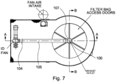
- the gases exit from the gas cleaning chamber in a centrally located outlet 100 and are then directed into a duct 102.
- the duct 102 is arranged perpendicular to the outlet duct 100.
- the duct 102 delivers the exhaust gases to a testing and measuring device located within the duct.
- the measuring device is arranged to measure species in the exhaust gases. Pollution species that may be measured include chlorides, hydrochlorides, sulphides, sulphur dioxides; nitrogen oxides and particulate material. Other species may also be monitored. Regulations specify the amount of pollutant that may be in the gases. According to present requirements the gases are arranged to travel in a straight line in the duct for a specified distance before entering the measuring device. It is understood that flow in a straight line for the specified distance leads to linear flow.
- Exhaust gases flow from the measuring device flow to a return duct 105 and to a chimney 107.
- the exhaust gases may be returned to a vent that is laterally located.
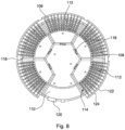
- Figure 7 is a plan view of the embodiment of Figure 6 .
- the upper section 20 is arranged above the bag cleaning chamber and the duct 102 extends from the exhaust outlet 100 from the gas cleaning chamber.
- each sub-chamber 108 comprises an section of the annular gas cleaning chamber 106.
- Each sub chamber 108 comprises an arc of approximately 60° of the annular chamber 106.
- a first sub chamber 110 does not contain any bag filters.
- the remaining five sub-chambers 112 each have a number of rows 114 of bag filters 116.
- a baffle 118 is provided at a top end of the five sub-chambers 112 and the baffle controls 118 flow of gas from the sub-chambers 112 to the first sub chamber 110 towards the outlet 120 into the duct 102.
- Pressurised air is supplied to an outer manifold 122.
- the pressurised air is fluidly connected to a number of inner manifolds 124 each of which is arranged to be able to supply the pressurised air to the bag filters 116.
- Valves are provided in each inner manifold to control a flow of pressurised pulse air to the bag filters 116.
- a controller is arranged to control the supply of air from the outer manifold to the bag filters 116.
- the baffle 118 controls a flow of air from an upper chamber above the gas cleaning chamber towards the measuring device and the chimney. Closing the baffle stops flow from the upper portion of the sub chambers towards the first sub chamber and into the outlet and duct to the measuring device. Exhaust gases tend to follow the course of least resistance and the flow of exhaust gases moves to flow through the sub chambers in respect of which the respective baffle remains open.
- one sub-chamber 112 is closed at a time. Once the respective baffle118 is closed the gases are not drawn through the closed sub chamber and gas flow on the immediately upstream side of the bag filter becomes stagnant.
- a particular advantage of the arrangement is that the boiler and gas cleaning apparatus can continue to be used while one of the bag cleaning sub-chambers is closed and the bag filters cleaned.
- the bag filters in the sub-chambers can be cleaned on a sequential arrangement. This contrasts with conventional boilers and gas cleaning arrangements in which the boiler and gas cleaning apparatus have to be suspended while cleaning of the bag filters is carried out.
- the pulsed air is controlled to be suppled from the outer manifold 122 and into the inner manifolds 114.
- a controller located remotely, is arranged to apply the pulsed air to the bag filters 116. Particulate material collected on the upstream side of the bag filters is displaced by the pulsed air and falls from the bag filter 116 and onto the rotatable floor located at the base of the gas cleaning chamber to be removed.
- Figure 9 is a cross section along the line A-A in Figure 7 .
- the boiler arrangement and the heat exchange apparatus is the same as in Figure 3 .
- the gases flow from the boiler 130 and into the radiant chamber 132 and then into the heat exchange chamber 134.
- Gases from the heat exchange chamber 134 flow to the base 136 of the heat exchange chamber and then upwardly into the annular gas cleaning chamber.
- Gases flowing through the gas cleaning chamber pass through the bag filters 116.
- Particulate material collects on the upstream side of the bag filters.
- pulsed air passing through the bag filters dislodges the particulate material which falls to the rotatable moving floor 138.
- the gases Downstream of the bag filters 116 the gases flow through the respective baffle 118 into the first sub-chamber 110 through the baffle and into the duct 102.
- the side ducting 102 carries gases to a testing device 104 which is compatible with standard testing requirements.
- the testing device is arranged after a section of straight ducting such that the gas flow is considered to be laminar on entry to the testing device. Downstream of the testing device the gases flow through a return valve 105 and is discharged into the chimney 107.
- the controller is arranged to clean each of the sub-chambers sequentially.
- An important aspect is that the bag filters are cleaned while the boiler is operating and that it is not necessary to stop or interrupt the operation of the boiler.
Landscapes
- Engineering & Computer Science (AREA)
- Mechanical Engineering (AREA)
- General Engineering & Computer Science (AREA)
- Chemical & Material Sciences (AREA)
- Combustion & Propulsion (AREA)
- Environmental & Geological Engineering (AREA)
- Oil, Petroleum & Natural Gas (AREA)
- Organic Chemistry (AREA)
- Life Sciences & Earth Sciences (AREA)
- Sustainable Development (AREA)
- Sustainable Energy (AREA)
- Chimneys And Flues (AREA)
Claims (14)
- Integrierte Einheit (1), die eine Kesseleinheit (2) und eine Gasreinigungseinrichtung, die Gasreinigungsmittel aufweist, umfasst, wobei die integrierte Einheit eine Reaktionseinheit aufweist, die einen Wirbelschichtkessel (4), einen Vergaser oder eine Pyrolysekammer umfasst, und wobei Brennstoff vollständig verbrannt, unter Pyrolysebedingungen verbrannt oder vergast wird, und ferner umfassend eine Strahlungszone (10), die mit der Reaktionseinheit verbunden ist, wobei die Strahlungszone (10) mit einer Konvektionszone (12) verbunden ist, wobei die integrierte Einheit (1) ferner ein Wärmetauschmittel umfasst, das mindestens eine der Strahlungszone (10) und der Konvektionszone (12) umgibt und eine ringförmige Wärmetauschkammer (14; 134) umfasst; dadurch gekennzeichnet, dass das Gasreinigungsmittel in einer ringförmigen Gasreinigungskammer (16; 106) bereitgestellt ist, die die Wärmetauschkammer umgibt, und dadurch, dass das Gasreinigungsmittel (76) eine Anordnung von Schlauchfiltern (76) in der Gasreinigungskammer (16; 106) umfasst, wobei das Schlauchfilter (76) mindestens eines von Gewebe-, Keramik- und Metallmaterial umfasst.
- Integrierte Einheit (1) nach Anspruch 1, wobei die Wärmetauschkammer (14; 134) und die Gasreinigungskammer (16; 106) derart angeordnet sind, dass die Strömung der Gase direkt hin zu und fluchtend mit den Schlauchfiltern (76) ist, und wobei die Gasreinigungskammer (16; 106) eine Anzahl von Teilkammern (108) umfasst, und wobei optional die Teilkammern (108) strömungstechnisch getrennt sind.
- Integrierte Einheit (1) nach Anspruch 2, wobei eine Zufuhr von Druckluft auf eine stromabwärtige Seite der Schlauchfilter (76) aufgebracht werden kann.
- Integrierte Einheit (1) nach Anspruch 3, die dazu angeordnet ist, Druckluft in einem Impuls aufzubringen, und wobei der Impuls auf jede Teilkammer (108) nacheinander aufgebracht wird und optional der Kessel (2) in Betrieb bleibt.
- Integrierte Einheit (1) nach einem der Ansprüche 1 bis 4, wobei ein Einspritzmittel bereitgestellt ist, das dazu angeordnet ist, ein Sorptionsmittel in die Gasreinigungskammer (16; 106) einzuspritzen.
- Integrierte Einheit (1) nach einem der Ansprüche 1 bis 5, wobei Abfallmaterial aus einer Basis der Gasreinigungskammer (16; 106) entfernt werden kann.
- Integrierte Einheit (1) nach einem der vorhergehenden Ansprüche, wobei die Gasreinigungskammer (16; 106) einen beweglichen Boden (138) umfasst.
- Integrierte Einheit (1) nach Anspruch 7, wobei der bewegliche Boden (138) einen rotierenden Boden umfasst, der mindestens eine Rührvorrichtung aufweist, die sich zwischen einem Innenband und einem Außenband erstreckt, und wobei die oder jede Rührvorrichtung dazu angeordnet ist, Abfallpartikel hin zu einem offenen Bereich zu bewegen.
- Integrierte Einheit (1) nach Anspruch 1, wobei die Strahlungszone (10) über der Reaktionseinheit positioniert ist.
- Integrierte Einheit (1) nach Anspruch 7, wobei die Konvektionszone (12) in freier strömungstechnischer Kommunikation mit der Strahlungszone (10) ist.
- Integrierte Einheit nach Anspruch 1, wobei mindestens eine Wand der ringförmigen Wärmetauschkammer (14; 134) durch mindestens ein spiralförmige gewundenes Wärmetauschrohr (76) ausgebildet ist und optional wobei die mindestens eine Wand auch mindestens einen Abschnitt der Strahlungszone (10) und der Konvektionszone (12) definiert.
- Integrierte Einheit (1) nach Anspruch 1, wobei die Wärmetauschkammer (14; 134) einen Vorwärmer und einen Verdampfer umfasst.
- Integrierte Einheit (1) nach einem der vorhergehenden Ansprüche, wobei ein Kamin mittig über den Strahlungs(10)- und Konvektions(12)-Zonen angeordnet ist.
- Integrierte Einheit (1) nach einem der vorhergehenden Ansprüche, die eine Grundfläche aufweist, die die eines Wirbelschichtkessels umfasst.
Applications Claiming Priority (2)
| Application Number | Priority Date | Filing Date | Title |
|---|---|---|---|
| GBGB1701385.5A GB201701385D0 (en) | 2017-01-27 | 2017-01-27 | Boiler unit |
| PCT/GB2018/050216 WO2018138505A1 (en) | 2017-01-27 | 2018-01-25 | Boiler unit |
Publications (2)
| Publication Number | Publication Date |
|---|---|
| EP3574261A1 EP3574261A1 (de) | 2019-12-04 |
| EP3574261B1 true EP3574261B1 (de) | 2023-06-07 |
Family
ID=58462613
Family Applications (1)
| Application Number | Title | Priority Date | Filing Date |
|---|---|---|---|
| EP18702535.8A Active EP3574261B1 (de) | 2017-01-27 | 2018-01-25 | Boilereinheit |
Country Status (4)
| Country | Link |
|---|---|
| US (1) | US20190390855A1 (de) |
| EP (1) | EP3574261B1 (de) |
| GB (1) | GB201701385D0 (de) |
| WO (1) | WO2018138505A1 (de) |
Families Citing this family (1)
| Publication number | Priority date | Publication date | Assignee | Title |
|---|---|---|---|---|
| CN114370640B (zh) * | 2021-12-28 | 2022-11-04 | 江苏大昱环保工程有限公司 | 一种蓄热式焚化炉的改良结构 |
Citations (1)
| Publication number | Priority date | Publication date | Assignee | Title |
|---|---|---|---|---|
| US20110083593A1 (en) * | 2009-10-12 | 2011-04-14 | AirClean Technologies, Inc. | Fluidized combustor |
Family Cites Families (4)
| Publication number | Priority date | Publication date | Assignee | Title |
|---|---|---|---|---|
| FR1276975A (fr) * | 1960-12-27 | 1961-11-24 | Perfectionnements aux foyers à combustion en suspension aérodynamique | |
| CH585876A5 (de) * | 1975-05-07 | 1977-03-15 | Ofag Ofenbau Feuerungstech Ag | |
| DE3644030A1 (de) * | 1986-12-22 | 1988-08-04 | Siemens Ag | Aufgeladener, kohlebefeuerter dampferzeuger |
| US7644669B2 (en) * | 2007-05-03 | 2010-01-12 | Alan Cross | Coal fired process heaters |
-
2017
- 2017-01-27 GB GBGB1701385.5A patent/GB201701385D0/en not_active Ceased
-
2018
- 2018-01-25 EP EP18702535.8A patent/EP3574261B1/de active Active
- 2018-01-25 WO PCT/GB2018/050216 patent/WO2018138505A1/en not_active Ceased
- 2018-01-25 US US16/481,365 patent/US20190390855A1/en not_active Abandoned
Patent Citations (1)
| Publication number | Priority date | Publication date | Assignee | Title |
|---|---|---|---|---|
| US20110083593A1 (en) * | 2009-10-12 | 2011-04-14 | AirClean Technologies, Inc. | Fluidized combustor |
Also Published As
| Publication number | Publication date |
|---|---|
| EP3574261A1 (de) | 2019-12-04 |
| WO2018138505A1 (en) | 2018-08-02 |
| GB201701385D0 (en) | 2017-03-15 |
| US20190390855A1 (en) | 2019-12-26 |
Similar Documents
| Publication | Publication Date | Title |
|---|---|---|
| CA2613427C (en) | Method and apparatus for automated, modular, biomass power generation | |
| KR950009002B1 (ko) | 가스화 물질을 가스화하고 및/또는 가스를 개질하기 위한 공정 및 장치 및 그 방법을 실시하기 위한 고온 열교환기 | |
| JPH01115995A (ja) | ガス化装置 | |
| KR101209022B1 (ko) | 열회수율이 향상된 열회수시스템 및 이를 이용한 열병합 발전시스템 | |
| CN102345850B (zh) | 具有改进的热回收率的热回收系统及利用该系统的热电联产系统 | |
| EP3574261B1 (de) | Boilereinheit | |
| CN106989400B (zh) | 一种吸附VOCs废气固体废弃物蓄热沸腾燃烧沉降净化装置的使用方法 | |
| CN109724087B (zh) | 一种生活垃圾焚烧烟气处理一体化系统 | |
| RU144018U1 (ru) | Установка термохимической генерации энергетических газов из твердого топлива (варианты) | |
| CN107023839B (zh) | 一种处理吸附VOCs废气固体废弃物蓄热沸腾燃烧炉的使用方法 | |
| CN100523612C (zh) | 废弃物的热分解处理装置和热分解处理装置的控制方法 | |
| RU2617230C2 (ru) | Переносная установка-модуль для термической переработки твердых бытовых отходов на полигоне | |
| CN107023836B (zh) | 一种吸附VOCs废气固体废弃物蓄热沸腾燃烧沉降净化装置 | |
| CN209263694U (zh) | 一种用于钢铁厂含铁尘泥处理的推式多层炉装置 | |
| US4124681A (en) | Particulate carbon disposal by combustion | |
| JP3819615B2 (ja) | 廃棄物の乾留熱分解溶融燃焼装置 | |
| RU2423647C1 (ru) | Термогазохимическая установка для утилизации твердых бытовых отходов | |
| RU208397U1 (ru) | Циклонная камера дожигания дымовых газов для деструкции стойких органических загрязнителей | |
| CN102688686A (zh) | 一种垃圾焚烧烟气除尘催化脱硝反应装置 | |
| CN109443022B (zh) | 一种用于钢铁厂含铁尘泥处理的推式多层炉装置 | |
| PL234563B1 (pl) | Reaktor cyklonowy | |
| CN116481020A (zh) | 一种包含一个以上烟气涡流燃烧室的烟气后燃烧装置 | |
| WO1982001055A1 (en) | Apparatus for processing industrial gases | |
| PL234564B1 (pl) | Reaktor cyklonowy cylindryczny | |
| EA018758B1 (ru) | Котел водогрейный |
Legal Events
| Date | Code | Title | Description |
|---|---|---|---|
| STAA | Information on the status of an ep patent application or granted ep patent |
Free format text: STATUS: UNKNOWN |
|
| STAA | Information on the status of an ep patent application or granted ep patent |
Free format text: STATUS: THE INTERNATIONAL PUBLICATION HAS BEEN MADE |
|
| PUAI | Public reference made under article 153(3) epc to a published international application that has entered the european phase |
Free format text: ORIGINAL CODE: 0009012 |
|
| STAA | Information on the status of an ep patent application or granted ep patent |
Free format text: STATUS: REQUEST FOR EXAMINATION WAS MADE |
|
| 17P | Request for examination filed |
Effective date: 20190822 |
|
| AK | Designated contracting states |
Kind code of ref document: A1 Designated state(s): AL AT BE BG CH CY CZ DE DK EE ES FI FR GB GR HR HU IE IS IT LI LT LU LV MC MK MT NL NO PL PT RO RS SE SI SK SM TR |
|
| AX | Request for extension of the european patent |
Extension state: BA ME |
|
| DAV | Request for validation of the european patent (deleted) | ||
| DAX | Request for extension of the european patent (deleted) | ||
| 19U | Interruption of proceedings before grant |
Effective date: 20200131 |
|
| 19W | Proceedings resumed before grant after interruption of proceedings |
Effective date: 20210201 |
|
| STAA | Information on the status of an ep patent application or granted ep patent |
Free format text: STATUS: EXAMINATION IS IN PROGRESS |
|
| 111Z | Information provided on other rights and legal means of execution |
Free format text: AL AT BE BG CH CY CZ DE DK EE ES FI FR GB GR HR HU IE IS IT LT LU LV MC MK MT NL NO PL PT RO RS SE SI SK SM TR Effective date: 20210201 |
|
| 17Q | First examination report despatched |
Effective date: 20210209 |
|
| RAP1 | Party data changed (applicant data changed or rights of an application transferred) |
Owner name: STRUTHERS ENERGY & POWER LIMITED |
|
| GRAP | Despatch of communication of intention to grant a patent |
Free format text: ORIGINAL CODE: EPIDOSNIGR1 |
|
| STAA | Information on the status of an ep patent application or granted ep patent |
Free format text: STATUS: GRANT OF PATENT IS INTENDED |
|
| INTG | Intention to grant announced |
Effective date: 20220822 |
|
| GRAS | Grant fee paid |
Free format text: ORIGINAL CODE: EPIDOSNIGR3 |
|
| GRAA | (expected) grant |
Free format text: ORIGINAL CODE: 0009210 |
|
| STAA | Information on the status of an ep patent application or granted ep patent |
Free format text: STATUS: THE PATENT HAS BEEN GRANTED |
|
| AK | Designated contracting states |
Kind code of ref document: B1 Designated state(s): AL AT BE BG CH CY CZ DE DK EE ES FI FR GB GR HR HU IE IS IT LI LT LU LV MC MK MT NL NO PL PT RO RS SE SI SK SM TR |
|
| REG | Reference to a national code |
Ref country code: GB Ref legal event code: FG4D |
|
| REG | Reference to a national code |
Ref country code: CH Ref legal event code: EP Ref country code: AT Ref legal event code: REF Ref document number: 1576114 Country of ref document: AT Kind code of ref document: T Effective date: 20230615 |
|
| REG | Reference to a national code |
Ref country code: DE Ref legal event code: R096 Ref document number: 602018050873 Country of ref document: DE |
|
| REG | Reference to a national code |
Ref country code: LT Ref legal event code: MG9D |
|
| REG | Reference to a national code |
Ref country code: NL Ref legal event code: MP Effective date: 20230607 |
|
| PG25 | Lapsed in a contracting state [announced via postgrant information from national office to epo] |
Ref country code: SE Free format text: LAPSE BECAUSE OF FAILURE TO SUBMIT A TRANSLATION OF THE DESCRIPTION OR TO PAY THE FEE WITHIN THE PRESCRIBED TIME-LIMIT Effective date: 20230607 Ref country code: NO Free format text: LAPSE BECAUSE OF FAILURE TO SUBMIT A TRANSLATION OF THE DESCRIPTION OR TO PAY THE FEE WITHIN THE PRESCRIBED TIME-LIMIT Effective date: 20230907 Ref country code: ES Free format text: LAPSE BECAUSE OF FAILURE TO SUBMIT A TRANSLATION OF THE DESCRIPTION OR TO PAY THE FEE WITHIN THE PRESCRIBED TIME-LIMIT Effective date: 20230607 |
|
| REG | Reference to a national code |
Ref country code: AT Ref legal event code: MK05 Ref document number: 1576114 Country of ref document: AT Kind code of ref document: T Effective date: 20230607 |
|
| PG25 | Lapsed in a contracting state [announced via postgrant information from national office to epo] |
Ref country code: RS Free format text: LAPSE BECAUSE OF FAILURE TO SUBMIT A TRANSLATION OF THE DESCRIPTION OR TO PAY THE FEE WITHIN THE PRESCRIBED TIME-LIMIT Effective date: 20230607 Ref country code: NL Free format text: LAPSE BECAUSE OF FAILURE TO SUBMIT A TRANSLATION OF THE DESCRIPTION OR TO PAY THE FEE WITHIN THE PRESCRIBED TIME-LIMIT Effective date: 20230607 Ref country code: LV Free format text: LAPSE BECAUSE OF FAILURE TO SUBMIT A TRANSLATION OF THE DESCRIPTION OR TO PAY THE FEE WITHIN THE PRESCRIBED TIME-LIMIT Effective date: 20230607 Ref country code: LT Free format text: LAPSE BECAUSE OF FAILURE TO SUBMIT A TRANSLATION OF THE DESCRIPTION OR TO PAY THE FEE WITHIN THE PRESCRIBED TIME-LIMIT Effective date: 20230607 Ref country code: HR Free format text: LAPSE BECAUSE OF FAILURE TO SUBMIT A TRANSLATION OF THE DESCRIPTION OR TO PAY THE FEE WITHIN THE PRESCRIBED TIME-LIMIT Effective date: 20230607 Ref country code: GR Free format text: LAPSE BECAUSE OF FAILURE TO SUBMIT A TRANSLATION OF THE DESCRIPTION OR TO PAY THE FEE WITHIN THE PRESCRIBED TIME-LIMIT Effective date: 20230908 |
|
| PG25 | Lapsed in a contracting state [announced via postgrant information from national office to epo] |
Ref country code: FI Free format text: LAPSE BECAUSE OF FAILURE TO SUBMIT A TRANSLATION OF THE DESCRIPTION OR TO PAY THE FEE WITHIN THE PRESCRIBED TIME-LIMIT Effective date: 20230607 |
|
| PG25 | Lapsed in a contracting state [announced via postgrant information from national office to epo] |
Ref country code: SK Free format text: LAPSE BECAUSE OF FAILURE TO SUBMIT A TRANSLATION OF THE DESCRIPTION OR TO PAY THE FEE WITHIN THE PRESCRIBED TIME-LIMIT Effective date: 20230607 |
|
| PG25 | Lapsed in a contracting state [announced via postgrant information from national office to epo] |
Ref country code: IS Free format text: LAPSE BECAUSE OF FAILURE TO SUBMIT A TRANSLATION OF THE DESCRIPTION OR TO PAY THE FEE WITHIN THE PRESCRIBED TIME-LIMIT Effective date: 20231007 |
|
| PG25 | Lapsed in a contracting state [announced via postgrant information from national office to epo] |
Ref country code: SM Free format text: LAPSE BECAUSE OF FAILURE TO SUBMIT A TRANSLATION OF THE DESCRIPTION OR TO PAY THE FEE WITHIN THE PRESCRIBED TIME-LIMIT Effective date: 20230607 Ref country code: SK Free format text: LAPSE BECAUSE OF FAILURE TO SUBMIT A TRANSLATION OF THE DESCRIPTION OR TO PAY THE FEE WITHIN THE PRESCRIBED TIME-LIMIT Effective date: 20230607 Ref country code: RO Free format text: LAPSE BECAUSE OF FAILURE TO SUBMIT A TRANSLATION OF THE DESCRIPTION OR TO PAY THE FEE WITHIN THE PRESCRIBED TIME-LIMIT Effective date: 20230607 Ref country code: PT Free format text: LAPSE BECAUSE OF FAILURE TO SUBMIT A TRANSLATION OF THE DESCRIPTION OR TO PAY THE FEE WITHIN THE PRESCRIBED TIME-LIMIT Effective date: 20231009 Ref country code: IS Free format text: LAPSE BECAUSE OF FAILURE TO SUBMIT A TRANSLATION OF THE DESCRIPTION OR TO PAY THE FEE WITHIN THE PRESCRIBED TIME-LIMIT Effective date: 20231007 Ref country code: EE Free format text: LAPSE BECAUSE OF FAILURE TO SUBMIT A TRANSLATION OF THE DESCRIPTION OR TO PAY THE FEE WITHIN THE PRESCRIBED TIME-LIMIT Effective date: 20230607 Ref country code: CZ Free format text: LAPSE BECAUSE OF FAILURE TO SUBMIT A TRANSLATION OF THE DESCRIPTION OR TO PAY THE FEE WITHIN THE PRESCRIBED TIME-LIMIT Effective date: 20230607 Ref country code: AT Free format text: LAPSE BECAUSE OF FAILURE TO SUBMIT A TRANSLATION OF THE DESCRIPTION OR TO PAY THE FEE WITHIN THE PRESCRIBED TIME-LIMIT Effective date: 20230607 |
|
| PG25 | Lapsed in a contracting state [announced via postgrant information from national office to epo] |
Ref country code: PL Free format text: LAPSE BECAUSE OF FAILURE TO SUBMIT A TRANSLATION OF THE DESCRIPTION OR TO PAY THE FEE WITHIN THE PRESCRIBED TIME-LIMIT Effective date: 20230607 |
|
| REG | Reference to a national code |
Ref country code: DE Ref legal event code: R097 Ref document number: 602018050873 Country of ref document: DE |
|
| PLBE | No opposition filed within time limit |
Free format text: ORIGINAL CODE: 0009261 |
|
| STAA | Information on the status of an ep patent application or granted ep patent |
Free format text: STATUS: NO OPPOSITION FILED WITHIN TIME LIMIT |
|
| PG25 | Lapsed in a contracting state [announced via postgrant information from national office to epo] |
Ref country code: DK Free format text: LAPSE BECAUSE OF FAILURE TO SUBMIT A TRANSLATION OF THE DESCRIPTION OR TO PAY THE FEE WITHIN THE PRESCRIBED TIME-LIMIT Effective date: 20230607 |
|
| PG25 | Lapsed in a contracting state [announced via postgrant information from national office to epo] |
Ref country code: SI Free format text: LAPSE BECAUSE OF FAILURE TO SUBMIT A TRANSLATION OF THE DESCRIPTION OR TO PAY THE FEE WITHIN THE PRESCRIBED TIME-LIMIT Effective date: 20230607 |
|
| 26N | No opposition filed |
Effective date: 20240308 |
|
| PG25 | Lapsed in a contracting state [announced via postgrant information from national office to epo] |
Ref country code: SI Free format text: LAPSE BECAUSE OF FAILURE TO SUBMIT A TRANSLATION OF THE DESCRIPTION OR TO PAY THE FEE WITHIN THE PRESCRIBED TIME-LIMIT Effective date: 20230607 Ref country code: IT Free format text: LAPSE BECAUSE OF FAILURE TO SUBMIT A TRANSLATION OF THE DESCRIPTION OR TO PAY THE FEE WITHIN THE PRESCRIBED TIME-LIMIT Effective date: 20230607 |
|
| REG | Reference to a national code |
Ref country code: DE Ref legal event code: R119 Ref document number: 602018050873 Country of ref document: DE |
|
| PG25 | Lapsed in a contracting state [announced via postgrant information from national office to epo] |
Ref country code: MC Free format text: LAPSE BECAUSE OF FAILURE TO SUBMIT A TRANSLATION OF THE DESCRIPTION OR TO PAY THE FEE WITHIN THE PRESCRIBED TIME-LIMIT Effective date: 20230607 |
|
| PG25 | Lapsed in a contracting state [announced via postgrant information from national office to epo] |
Ref country code: MC Free format text: LAPSE BECAUSE OF FAILURE TO SUBMIT A TRANSLATION OF THE DESCRIPTION OR TO PAY THE FEE WITHIN THE PRESCRIBED TIME-LIMIT Effective date: 20230607 |
|
| REG | Reference to a national code |
Ref country code: CH Ref legal event code: PL |
|
| PG25 | Lapsed in a contracting state [announced via postgrant information from national office to epo] |
Ref country code: LU Free format text: LAPSE BECAUSE OF NON-PAYMENT OF DUE FEES Effective date: 20240125 |
|
| PG25 | Lapsed in a contracting state [announced via postgrant information from national office to epo] |
Ref country code: LU Free format text: LAPSE BECAUSE OF NON-PAYMENT OF DUE FEES Effective date: 20240125 |
|
| PG25 | Lapsed in a contracting state [announced via postgrant information from national office to epo] |
Ref country code: DE Free format text: LAPSE BECAUSE OF NON-PAYMENT OF DUE FEES Effective date: 20240801 |
|
| PG25 | Lapsed in a contracting state [announced via postgrant information from national office to epo] |
Ref country code: BE Free format text: LAPSE BECAUSE OF NON-PAYMENT OF DUE FEES Effective date: 20240131 |
|
| PG25 | Lapsed in a contracting state [announced via postgrant information from national office to epo] |
Ref country code: FR Free format text: LAPSE BECAUSE OF NON-PAYMENT OF DUE FEES Effective date: 20240131 |
|
| PG25 | Lapsed in a contracting state [announced via postgrant information from national office to epo] |
Ref country code: CH Free format text: LAPSE BECAUSE OF NON-PAYMENT OF DUE FEES Effective date: 20240131 |
|
| PG25 | Lapsed in a contracting state [announced via postgrant information from national office to epo] |
Ref country code: FR Free format text: LAPSE BECAUSE OF NON-PAYMENT OF DUE FEES Effective date: 20240131 Ref country code: DE Free format text: LAPSE BECAUSE OF NON-PAYMENT OF DUE FEES Effective date: 20240801 Ref country code: CH Free format text: LAPSE BECAUSE OF NON-PAYMENT OF DUE FEES Effective date: 20240131 Ref country code: BE Free format text: LAPSE BECAUSE OF NON-PAYMENT OF DUE FEES Effective date: 20240131 |
|
| REG | Reference to a national code |
Ref country code: BE Ref legal event code: MM Effective date: 20240131 |
|
| PG25 | Lapsed in a contracting state [announced via postgrant information from national office to epo] |
Ref country code: BG Free format text: LAPSE BECAUSE OF FAILURE TO SUBMIT A TRANSLATION OF THE DESCRIPTION OR TO PAY THE FEE WITHIN THE PRESCRIBED TIME-LIMIT Effective date: 20230607 |
|
| PG25 | Lapsed in a contracting state [announced via postgrant information from national office to epo] |
Ref country code: BG Free format text: LAPSE BECAUSE OF FAILURE TO SUBMIT A TRANSLATION OF THE DESCRIPTION OR TO PAY THE FEE WITHIN THE PRESCRIBED TIME-LIMIT Effective date: 20230607 |
|
| PGFP | Annual fee paid to national office [announced via postgrant information from national office to epo] |
Ref country code: GB Payment date: 20241105 Year of fee payment: 8 |
|
| PG25 | Lapsed in a contracting state [announced via postgrant information from national office to epo] |
Ref country code: IE Free format text: LAPSE BECAUSE OF NON-PAYMENT OF DUE FEES Effective date: 20240125 |
|
| PG25 | Lapsed in a contracting state [announced via postgrant information from national office to epo] |
Ref country code: IE Free format text: LAPSE BECAUSE OF NON-PAYMENT OF DUE FEES Effective date: 20240125 |
|
| PG25 | Lapsed in a contracting state [announced via postgrant information from national office to epo] |
Ref country code: CY Free format text: LAPSE BECAUSE OF FAILURE TO SUBMIT A TRANSLATION OF THE DESCRIPTION OR TO PAY THE FEE WITHIN THE PRESCRIBED TIME-LIMIT; INVALID AB INITIO Effective date: 20180125 |
|
| PG25 | Lapsed in a contracting state [announced via postgrant information from national office to epo] |
Ref country code: HU Free format text: LAPSE BECAUSE OF FAILURE TO SUBMIT A TRANSLATION OF THE DESCRIPTION OR TO PAY THE FEE WITHIN THE PRESCRIBED TIME-LIMIT; INVALID AB INITIO Effective date: 20180125 |