EP3574248B2 - Hydraulische kupplungsbuchse mit flacher seite - Google Patents
Hydraulische kupplungsbuchse mit flacher seite Download PDFInfo
- Publication number
- EP3574248B2 EP3574248B2 EP18704454.0A EP18704454A EP3574248B2 EP 3574248 B2 EP3574248 B2 EP 3574248B2 EP 18704454 A EP18704454 A EP 18704454A EP 3574248 B2 EP3574248 B2 EP 3574248B2
- Authority
- EP
- European Patent Office
- Prior art keywords
- valve
- sleeve
- valve sleeve
- sealed
- guide
- Prior art date
- Legal status (The legal status is an assumption and is not a legal conclusion. Google has not performed a legal analysis and makes no representation as to the accuracy of the status listed.)
- Active
Links
Images

Classifications
-
- F—MECHANICAL ENGINEERING; LIGHTING; HEATING; WEAPONS; BLASTING
- F16—ENGINEERING ELEMENTS AND UNITS; GENERAL MEASURES FOR PRODUCING AND MAINTAINING EFFECTIVE FUNCTIONING OF MACHINES OR INSTALLATIONS; THERMAL INSULATION IN GENERAL
- F16L—PIPES; JOINTS OR FITTINGS FOR PIPES; SUPPORTS FOR PIPES, CABLES OR PROTECTIVE TUBING; MEANS FOR THERMAL INSULATION IN GENERAL
- F16L37/00—Couplings of the quick-acting type
- F16L37/22—Couplings of the quick-acting type in which the connection is maintained by means of balls, rollers or helical springs under radial pressure between the parts
- F16L37/23—Couplings of the quick-acting type in which the connection is maintained by means of balls, rollers or helical springs under radial pressure between the parts by means of balls
-
- F—MECHANICAL ENGINEERING; LIGHTING; HEATING; WEAPONS; BLASTING
- F16—ENGINEERING ELEMENTS AND UNITS; GENERAL MEASURES FOR PRODUCING AND MAINTAINING EFFECTIVE FUNCTIONING OF MACHINES OR INSTALLATIONS; THERMAL INSULATION IN GENERAL
- F16L—PIPES; JOINTS OR FITTINGS FOR PIPES; SUPPORTS FOR PIPES, CABLES OR PROTECTIVE TUBING; MEANS FOR THERMAL INSULATION IN GENERAL
- F16L37/00—Couplings of the quick-acting type
- F16L37/28—Couplings of the quick-acting type with fluid cut-off means
- F16L37/30—Couplings of the quick-acting type with fluid cut-off means with fluid cut-off means in each of two pipe-end fittings
- F16L37/32—Couplings of the quick-acting type with fluid cut-off means with fluid cut-off means in each of two pipe-end fittings at least one of two lift valves being opened automatically when the coupling is applied
- F16L37/34—Couplings of the quick-acting type with fluid cut-off means with fluid cut-off means in each of two pipe-end fittings at least one of two lift valves being opened automatically when the coupling is applied at least one of the lift valves being of the sleeve type, i.e. a sleeve being telescoped over an inner cylindrical wall
-
- F—MECHANICAL ENGINEERING; LIGHTING; HEATING; WEAPONS; BLASTING
- F16—ENGINEERING ELEMENTS AND UNITS; GENERAL MEASURES FOR PRODUCING AND MAINTAINING EFFECTIVE FUNCTIONING OF MACHINES OR INSTALLATIONS; THERMAL INSULATION IN GENERAL
- F16L—PIPES; JOINTS OR FITTINGS FOR PIPES; SUPPORTS FOR PIPES, CABLES OR PROTECTIVE TUBING; MEANS FOR THERMAL INSULATION IN GENERAL
- F16L37/00—Couplings of the quick-acting type
- F16L37/28—Couplings of the quick-acting type with fluid cut-off means
- F16L37/30—Couplings of the quick-acting type with fluid cut-off means with fluid cut-off means in each of two pipe-end fittings
- F16L37/32—Couplings of the quick-acting type with fluid cut-off means with fluid cut-off means in each of two pipe-end fittings at least one of two lift valves being opened automatically when the coupling is applied
- F16L37/35—Couplings of the quick-acting type with fluid cut-off means with fluid cut-off means in each of two pipe-end fittings at least one of two lift valves being opened automatically when the coupling is applied at least one of the valves having an axial bore communicating with lateral apertures
Definitions
- the invention relates to a flat face female hydraulic coupling comprising:
- valve sleeve is composed out of two sleeve parts, which both need to be slid to the second position to open the coupling and allowing for fluid to flow through the coupling.
- the valve sleeve has, when seen in a first axial direction, a first frontal axial surface which is in contact with fluid in the coupling. When seen in the opposite second axial direction, the valve sleeve has a second frontal axial surface. Clearly, the size of the first frontal axial surface differs from the size of the second frontal axial surface.
- WO 2011/134 484 A1 discloses a hydraulic coupling bush, comprising a bush housing, in which a bush tappet, an axially movable compression sleeve that surrounds the bush tappet in an axially parallel manner, and an axially movable retaining sleeve that surrounds the compression sleeve in an axially parallel manner are arranged in an axially parallel manner.
- the compression sleeve is exposed from the inside to a hydraulic fluid to be conveyed through the bush without applying axial force to the compression sleeve.
- DE 10 2014 010 570 A1 discloses a coupling part of a coupling for pressure medium lines for coupling with a corresponding coupling part of the coupling for pressure medium lines that has a housing with a flow channel and a coupling axis, and a sleeve-like closing valve displaceable back and forth axially within the flow channel, for closing off the flow channel in the uncoupled state of the coupling part.
- the closing valve has a closed valve position and an open valve position, closing off and not closing the flow channel, respectively.
- a plunger within the flow channel is displaceable back and forth and axially drives the closing valve in a valve opening direction during coupling.
- a plunger pin between the plunger and the closing valve within the flow channel is displaceable back and forth axially and transfers the movement of the plunger in the valve opening direction to the closing valve.
- the plunger pin is connected with the closing valve so as to be non-displaceable axially.
- a flat face female hydraulic coupling according to the preamble, which flat face female hydraulic coupling is characterized in that the part of the inner surface of the valve sleeve bordering the fluid chamber has a surface integrated normal vector perpendicular to the axial direction or equal to zero, wherein the inner surface of the valve sleeve is stepped with a first diameter and a second diameter, wherein the inner surface with the first diameter is sealed to the valve stem, wherein the outer surface of the valve sleeve is sealed to the valve guide, the outer surface having a diameter equal to the first diameter and wherein the first diameter is larger than the second diameter.
- a flat face female hydraulic coupling according to the preamble, which flat face female hydraulic coupling is characterized in that the part of the inner surface of the valve sleeve bordering the fluid chamber has a surface integrated normal vector perpendicular to the axial direction or equal to zero, wherein the valve sleeve has a cylindrical inner surface and wherein the inner surface of the valve sleeve is sealed to the valve stem in the first position and wherein the inner surface of the valve sleeve is sealed to the valve guide.
- the frontal axial surface in both opposite axial directions is made equal to cancel the resulting force due to a difference in size of both frontal axial surfaces.
- the flat face female hydraulic coupling can be coupled without effort and therefore manually with a flat face male hydraulic coupling.
- the valve sleeve can be slid from the first to the second position, independent of the height of the hydraulic pressure in the fluid chamber.
- a radially extending flange is arranged to the outer surface of the valve sleeve and spring means are arranged between the radially extending flange and the valve guide to urge the valve sleeve in the first position.
- valve sleeve has a cylindrical inner surface and the inner surface of the valve sleeve is sealed to the valve stem in the first position and the inner surface of the valve sleeve is sealed to the valve guide.
- Using a cylindrical inner surface and sealing both the valve stem and the valve guide to said cylindrical inner surface ensures that the inner surface of the valve sleeve bordering the fluid chamber does not have any axial surface components, which could generate in combination with a fluid pressure in the fluid chamber an axial force .
- the inner surface of the valve sleeve is stepped with a first diameter and a second diameter, wherein the inner surface with the first diameter is sealed to the valve stem, wherein the outer surface of the valve sleeve is sealed to the valve guide, the outer surface having a diameter equal to the first diameter and wherein the first diameter is larger than the second diameter.
- valve guide is sealed to the outer surface of the valve sleeve.
- Yet another embodiment of the flat face female hydraulic coupling according to the invention further comprises a locking sleeve slidingly arranged between the body and the valve sleeve, at least one radial channel arranged in the body, at least one locking ball arranged in the at least one radial channel and a locking ring slidingly arranged on the outside of the body over the at least one radial channel.
- the locking sleeve When a male coupling is inserted into the female coupling according to the invention, the locking sleeve is pushed inward releasing the at least one locking ball, which can engage into an outer groove on the male coupling.
- the locking ring will maintain the locking ball in this locking position until the locking ring is shifted and the locking ball is allowed to move back to its original position.
- the flat face female hydraulic coupling according to the invention further comprises second spring means arranged between the locking sleeve and the valve guide to urge the locking sleeve to a position covering the at least one radial channel.
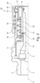
- a valve guide 5 is arranged on and sealed to the surface of the continuous passage 3.
- the valve guide 5 has a central passage 13.
- a valve stem 6 is furthermore coaxially arranged in the continuous passage 3.
- a valve sleeve 7 is arranged slidingly in axial direction. This valve sleeve 7 is sealed on one end with the inner surface by a seal 8 to the valve stem 6 and with the other end with the outer surface by a seal 9 to the valve guide 5.
- the body 2 has a radially extending channel 15 in which a locking ball 16 is arranged. On the inside the locking ball 16 is kept in position by a locking sleeve 17, which is urged by a spring 18. On the outside a slidable locking ring 19 is provided which has a cavity 20 in which the locking ball 16 is partially accommodated.
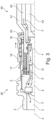
- Figure 2 shows a cross-sectional view of a second embodiment 30 of the flat face female hydraulic coupling according to the invention.
- This embodiment 30 partially corresponds to the embodiment 1 according to figure 1 and as a result similar components are designated with the same reference signs.
- the valve sleeve 31 is differently shaped and has a cylindrical inner surface 32.
- the inner surface 32 of the valve sleeve 31 seals with the seal 8 onto the valve stem 6 on one end and seals also on the inner surface 32 with a seal 33 onto the outside surface of the valve guide 5.
- the valve sleeve 31 is urged to the closed position by a spring 34.
- valve sleeve 31 bordering the fluid chamber Z 12 is fully cylindrical, no axial surface is present and so no axial force can be generated to counteract the sliding movement of the valve sleeve 31.
- Figure 3 shows a cross-sectional view of the female coupling 31 according to figure 2 coupled to a flat face male hydraulic coupling 40.
- the male coupling 40 has at least a body 41 with a continuous passage 42 and a valve body 43 axially movable in the continuous passage.
- the locking ball By sliding back the locking sleeve 17, the locking ball is free to move into a circumferential groove in the body 41 of the male coupling 40. At that moment, the locking ring 19 can slide such that the cavity 20 is no longer positioned above the channel with the locking ball 16 causing the locking ball 16 to be locked into the groove of the male coupling 40 and accordingly locking the female coupling 30 and the male coupling 40 together.
Landscapes
- Engineering & Computer Science (AREA)
- General Engineering & Computer Science (AREA)
- Mechanical Engineering (AREA)
- Quick-Acting Or Multi-Walled Pipe Joints (AREA)
Claims (5)
- Hydraulische Kupplungsbuchse mit flacher Stirnseite (1), Folgendes umfassend:- einen Körper (2) mit einem durchgehenden Durchgang (3), der sich in Axialrichtung (4) erstreckt;- eine Ventilspindel (6), die in dem durchgehenden Durchgang (3) des Körpers (2) koaxial angeordnet ist;- eine Ventilführung (5), die in dem durchgehenden Durchgang (3) des Körpers (2) koaxial angeordnet ist, wobei die Ventilführung (5) gegen die Fläche des durchgehenden Durchgangs (3) abdichtet und wobei die Ventilführung (5) einen mittleren Durchgang (13) umfasst;- eine Ventilmanschette (7), die in Axialrichtung zwischen einer ersten und einer zweiten Position in Bezug zur Ventilführung (5) verschiebbar angeordnet ist, wobei die Ventilmanschette (7) von der Ventilführung (5) geführt wird und wobei die Ventilmanschette (7) sowohl in der ersten als auch der zweiten Position an der Ventilführung (5) abdichtet und in der ersten Position an der Ventilspindel (6) abdichtet und in der zweiten Position ein Durchgang zwischen der Ventilspindel (6) und der Ventilmanschette (7) bereitgestellt wird;wobei in der ersten Position der Ventilmanschette (7) durch den mittleren Durchgang (13), die Innenfläche der Ventilmanschette (7) und die Ventilspindel (6) eine Fluidkammer ausgebildet wird;dadurch gekennzeichnet, dass das Oberflächenintegral des Normalvektors über den Teil der Innenfläche der Ventilmanschette (7), der an die Fluidkammer angrenzt, senkrecht zur Axialrichtung steht oder gleich Null ist,wobei die Innenfläche der Ventilmanschette (7) mit einem ersten Durchmesser (d1) und einem zweiten Durchmesser (d2) abgestuft ist, wobei die Innenfläche mit dem ersten Durchmesser (d1) an der Ventilspindel (6) abdichtet, wobei die Außenfläche der Ventilmanschette (7) an der Ventilführung (5) abdichtet, wobei die Außenfläche einen Durchmesser (d3) aufweist, der gleich dem ersten Durchmesser (d1) ist, und wobei der erste Durchmesser (d1) größer als der zweite Durchmesser (d2) ist.
- Hydraulische Kupplungsbuchse mit flacher Stirnseite (1), Folgendes umfassend:- einen Körper (2) mit einem durchgehenden Durchgang (3), der sich in Axialrichtung (4) erstreckt;
eine Ventilspindel (6), die in dem durchgehenden Durchgang (3) des Körpers (2) koaxial angeordnet ist;- eine Ventilführung (5), die in dem durchgehenden Durchgang (3) des Körpers (2) koaxial angeordnet ist, wobei die Ventilführung (5) gegen die Fläche des durchgehenden Durchgangs (3) abdichtet und wobei die Ventilführung (5) einen mittleren Durchgang (13) umfasst;- eine Ventilmanschette (7), die in Axialrichtung zwischen einer ersten und einer zweiten Position in Bezug zur Ventilführung (5) verschiebbar angeordnet ist, wobei die Ventilmanschette (7) von der Ventilführung (5) geführt wird und wobei die Ventilmanschette (7) sowohl in der ersten als auch der zweiten Position an der Ventilführung (5) abdichtet und in der ersten Position an der Ventilspindel (6) abdichtet und in der zweiten Position ein Durchgang zwischen der Ventilspindel (6) und der Ventilmanschette (7) bereitgestellt wird;wobei in der ersten Position der Ventilmanschette (7) durch den mittleren Durchgang (13), die Innenfläche der Ventilmanschette (7) und die Ventilspindel (6) eine Fluidkammer ausgebildet wird;dadurch gekennzeichnet, dass das Oberflächenintegral des Normalvektors über den Teil der Innenfläche der Ventilmanschette (7), der an die Fluidkammer angrenzt, senkrecht zur Axialrichtung steht oder gleich Null ist,wobei die Ventilmanschette (7) eine zylindrische Innenfläche aufweist und wobei die Innenfläche der Ventilmanschette (7) in der ersten Position an der Ventilspindel (6) abdichtet und wobei die Innenfläche der Ventilmanschette (7) an der Ventilführung (5) abdichtet. - Hydraulische Kupplungsbuchse mit flacher Stirnseite (1) nach Anspruch 1 oder 2, wobei ein sich radial erstreckender Flansch an der Außenfläche der Ventilmanschette (7) angeordnet ist und wobei eine Federeinrichtung zwischen dem sich radial erstreckenden Flansch und der Ventilführung (5) angeordnet ist, um die Ventilmanschette (7) in die erste Position zu drücken.
- Hydraulische Kupplungsbuchse mit flacher Stirnseite (1) nach einem der vorstehenden Ansprüche, ferner eine Sperrhülse (17) umfassend, die verschiebbar zwischen dem Körper (2) und der Ventilmanschette (7) angeordnet ist, wobei mindestens ein radialer Kanal (15) im Körper (2) angeordnet ist, wobei mindestens eine Sperrkugel (16) in dem mindestens einen radialen Kanal (15) angeordnet ist und wobei ein Sperrring (19) verschiebbar auf der Außenseite des Körpers (2) über dem mindestens einen radialen Kanal (15) angeordnet ist.
- Hydraulische Kupplungsbuchse mit flacher Stirnseite (1) nach Anspruch 4, ferner eine zweite Federeinrichtung umfassend, die zwischen der Sperrhülse (17) und der Ventilführung (5) angeordnet ist, um die Sperrhülse (17) in eine Position zu drücken, in der der mindestens eine radiale Kanal (15) abgedeckt wird.
Applications Claiming Priority (2)
| Application Number | Priority Date | Filing Date | Title |
|---|---|---|---|
| IN201711003111 | 2017-01-27 | ||
| PCT/EP2018/052000 WO2018138286A1 (en) | 2017-01-27 | 2018-01-26 | Flat face female hydraulic coupling |
Publications (3)
| Publication Number | Publication Date |
|---|---|
| EP3574248A1 EP3574248A1 (de) | 2019-12-04 |
| EP3574248B1 EP3574248B1 (de) | 2022-04-27 |
| EP3574248B2 true EP3574248B2 (de) | 2025-05-28 |
Family
ID=58688484
Family Applications (1)
| Application Number | Title | Priority Date | Filing Date |
|---|---|---|---|
| EP18704454.0A Active EP3574248B2 (de) | 2017-01-27 | 2018-01-26 | Hydraulische kupplungsbuchse mit flacher seite |
Country Status (6)
| Country | Link |
|---|---|
| US (1) | US11067208B2 (de) |
| EP (1) | EP3574248B2 (de) |
| CA (1) | CA3051310C (de) |
| DK (1) | DK3574248T4 (de) |
| GB (1) | GB2559209A (de) |
| WO (1) | WO2018138286A1 (de) |
Families Citing this family (6)
| Publication number | Priority date | Publication date | Assignee | Title |
|---|---|---|---|---|
| WO2020057879A1 (en) * | 2018-09-21 | 2020-03-26 | Eaton Intelligent Power Limited | Female hydraulic coupling, male hydraulic coupling and combination thereof |
| WO2020198248A1 (en) * | 2019-03-26 | 2020-10-01 | Rusoh, Inc. | Coupler for fire extinguisher nozzle accessory |
| US12038113B2 (en) | 2019-06-10 | 2024-07-16 | Colder Products Company | Fluid handling couplings |
| FR3101389B1 (fr) * | 2019-09-30 | 2021-10-22 | Staubli Sa Ets | Raccord fluidique |
| EP4390207B1 (de) | 2022-12-20 | 2024-10-23 | Walter Stauffenberg Gmbh & Co. Kg | Kupplungsteil für eine hydraulikkupplung |
| US20250020254A1 (en) * | 2023-07-12 | 2025-01-16 | Blue Origin, Llc | Quick disconnect coupling systems and related methods |
Citations (2)
| Publication number | Priority date | Publication date | Assignee | Title |
|---|---|---|---|---|
| WO2011134484A1 (de) † | 2010-04-30 | 2011-11-03 | Rheinisch-Westfälische Technische Hochschule Aachen | Hydraulikkupplungsmuffe |
| DE102014010570A1 (de) † | 2014-07-16 | 2016-01-21 | Voswinkel Entwicklungs- Und Verwaltungs-Gmbh & Co. Kg | Kupplungsteil für eine Kupplung für Druckmittelleitungen |
Family Cites Families (14)
| Publication number | Priority date | Publication date | Assignee | Title |
|---|---|---|---|---|
| US4124228A (en) * | 1977-03-24 | 1978-11-07 | Kaiser Aerospace & Electronics Corporation | Pressure-balanced fluid coupling |
| DE3041305A1 (de) * | 1980-11-03 | 1982-06-03 | Aeroquip GmbH, 3510 Hann Münden | Kupplung fuer hydrauliksysteme |
| US5179976A (en) * | 1991-12-23 | 1993-01-19 | Aeroquip Corporation | Fluid coupling |
| IT1270206B (it) * | 1994-06-10 | 1997-04-29 | Faster Srl | Innesto rapido per fluidi sotto pressione |
| ITMI20011105A1 (it) | 2001-05-25 | 2002-11-25 | Faster Srl | Innesto rapido a faccia piana, con mezzi per evitare una fuoriuscita di fluido idraulico durante la fase di accoppiamento o di disaccoppiame |
| DE10351997A1 (de) | 2003-11-07 | 2005-06-09 | Stammer, Arno, Dipl.-Ing. (TU) | Flachdichtende Hydraulikkupplung für Festeinbau mit steck- und abziehbarem Kupplungsstecker |
| DE102007025787A1 (de) * | 2007-05-24 | 2008-11-27 | Faster S.P.A. | Rohrkupplung, Verfahren zum Rohrkuppeln, und zur Selbstreinigung von Kupplungshälften beim Rohrkuppeln |
| CN201428887Y (zh) * | 2009-04-09 | 2010-03-24 | 新乡平原航空液压设备有限公司 | 一种快速接头 |
| ITMI20130522A1 (it) * | 2013-04-05 | 2014-10-06 | Alfa Gomma S P A | Innesto rapido idraulico o oleodimamico per fluido in pressione |
| ES2601225T3 (es) * | 2013-12-10 | 2017-02-14 | Faster S.P.A. | Dispositivo multiconector para la conexión rápida múltiple de múltiples líneas hidráulicas, eléctricas y/o neumáticas, con la posibilidad de conectores manuales individuales |
| CA2895873C (en) * | 2014-06-30 | 2019-01-08 | Parker-Hannifin Corporation | Inline connect breakaway hose coupler |
| EP3191759B1 (de) * | 2014-09-08 | 2018-06-06 | Alfa Gomma S.p.A. | Schnellkupplung für ein unter druck stehendes fluid |
| DE102015222639A1 (de) * | 2015-11-17 | 2017-05-18 | U.M. Gewerbeimmobilien Gmbh & Co. Kg | Kupplungsmuffe für eine Hydraulikkupplung |
| DE102015222640B4 (de) * | 2015-11-17 | 2021-08-26 | U.M. Gewerbeimmobilien Gmbh & Co. Kg | Kupplungselement und Ventilstößel für eine Kupplung zur Verbindung von Druckmittelleitungen |
-
2017
- 2017-03-16 GB GB1704213.6A patent/GB2559209A/en not_active Withdrawn
-
2018
- 2018-01-26 CA CA3051310A patent/CA3051310C/en active Active
- 2018-01-26 US US16/480,716 patent/US11067208B2/en active Active
- 2018-01-26 EP EP18704454.0A patent/EP3574248B2/de active Active
- 2018-01-26 DK DK18704454.0T patent/DK3574248T4/da active
- 2018-01-26 WO PCT/EP2018/052000 patent/WO2018138286A1/en not_active Ceased
Patent Citations (2)
| Publication number | Priority date | Publication date | Assignee | Title |
|---|---|---|---|---|
| WO2011134484A1 (de) † | 2010-04-30 | 2011-11-03 | Rheinisch-Westfälische Technische Hochschule Aachen | Hydraulikkupplungsmuffe |
| DE102014010570A1 (de) † | 2014-07-16 | 2016-01-21 | Voswinkel Entwicklungs- Und Verwaltungs-Gmbh & Co. Kg | Kupplungsteil für eine Kupplung für Druckmittelleitungen |
Also Published As
| Publication number | Publication date |
|---|---|
| GB201704213D0 (en) | 2017-05-03 |
| CA3051310A1 (en) | 2018-08-02 |
| CA3051310C (en) | 2020-10-27 |
| US11067208B2 (en) | 2021-07-20 |
| DK3574248T3 (da) | 2022-06-07 |
| EP3574248B1 (de) | 2022-04-27 |
| EP3574248A1 (de) | 2019-12-04 |
| GB2559209A (en) | 2018-08-01 |
| US20190390810A1 (en) | 2019-12-26 |
| DK3574248T4 (da) | 2025-07-07 |
| WO2018138286A1 (en) | 2018-08-02 |
Similar Documents
| Publication | Publication Date | Title |
|---|---|---|
| EP3574248B2 (de) | Hydraulische kupplungsbuchse mit flacher seite | |
| US5709243A (en) | Low spill female coupling | |
| CA3051306C (en) | Flat face male hydraulic coupling | |
| EP2431647B1 (de) | Hydraulikanschlussstutzen für Rohre | |
| US10036502B2 (en) | Fluid transmission coupling with independent member pressure relieving cam | |
| JP6618477B2 (ja) | 流体搬送接続具 | |
| CN107013776A (zh) | 快插接头的插槽件与包括此插槽件的快插接头 | |
| EP3369980B1 (de) | Abdichtventil für restdruck in pneumatischen federungen von fahrzeugen | |
| WO2020057879A1 (en) | Female hydraulic coupling, male hydraulic coupling and combination thereof | |
| JP2021036163A (ja) | カップリング装置 | |
| US4903730A (en) | Pipe coupling used with automatic connecting and disconnecting device | |
| GB2577345A (en) | Female hydraulic coupling, male hydraulic coupling and combination thereof | |
| IT201900015731A1 (it) | Sistema di connessione di tubo per tubazioni idrauliche di un veicolo fuoristrada | |
| NZ721040B2 (en) | Fluid transmission coupling with independent member pressure relieving cam | |
| NZ721042B2 (en) | Fluid transmission flat-face coupler with frontal annular seal |
Legal Events
| Date | Code | Title | Description |
|---|---|---|---|
| STAA | Information on the status of an ep patent application or granted ep patent |
Free format text: STATUS: UNKNOWN |
|
| STAA | Information on the status of an ep patent application or granted ep patent |
Free format text: STATUS: THE INTERNATIONAL PUBLICATION HAS BEEN MADE |
|
| PUAI | Public reference made under article 153(3) epc to a published international application that has entered the european phase |
Free format text: ORIGINAL CODE: 0009012 |
|
| STAA | Information on the status of an ep patent application or granted ep patent |
Free format text: STATUS: REQUEST FOR EXAMINATION WAS MADE |
|
| 17P | Request for examination filed |
Effective date: 20190820 |
|
| AK | Designated contracting states |
Kind code of ref document: A1 Designated state(s): AL AT BE BG CH CY CZ DE DK EE ES FI FR GB GR HR HU IE IS IT LI LT LU LV MC MK MT NL NO PL PT RO RS SE SI SK SM TR |
|
| AX | Request for extension of the european patent |
Extension state: BA ME |
|
| DAV | Request for validation of the european patent (deleted) | ||
| DAX | Request for extension of the european patent (deleted) | ||
| STAA | Information on the status of an ep patent application or granted ep patent |
Free format text: STATUS: EXAMINATION IS IN PROGRESS |
|
| 17Q | First examination report despatched |
Effective date: 20210216 |
|
| GRAP | Despatch of communication of intention to grant a patent |
Free format text: ORIGINAL CODE: EPIDOSNIGR1 |
|
| STAA | Information on the status of an ep patent application or granted ep patent |
Free format text: STATUS: GRANT OF PATENT IS INTENDED |
|
| INTG | Intention to grant announced |
Effective date: 20211124 |
|
| GRAS | Grant fee paid |
Free format text: ORIGINAL CODE: EPIDOSNIGR3 |
|
| GRAA | (expected) grant |
Free format text: ORIGINAL CODE: 0009210 |
|
| STAA | Information on the status of an ep patent application or granted ep patent |
Free format text: STATUS: THE PATENT HAS BEEN GRANTED |
|
| RAP1 | Party data changed (applicant data changed or rights of an application transferred) |
Owner name: DANFOSS POWER SOLUTIONS II |
|
| AK | Designated contracting states |
Kind code of ref document: B1 Designated state(s): AL AT BE BG CH CY CZ DE DK EE ES FI FR GB GR HR HU IE IS IT LI LT LU LV MC MK MT NL NO PL PT RO RS SE SI SK SM TR |
|
| REG | Reference to a national code |
Ref country code: GB Ref legal event code: FG4D |
|
| REG | Reference to a national code |
Ref country code: CH Ref legal event code: EP |
|
| REG | Reference to a national code |
Ref country code: DE Ref legal event code: R096 Ref document number: 602018034480 Country of ref document: DE |
|
| REG | Reference to a national code |
Ref country code: AT Ref legal event code: REF Ref document number: 1487168 Country of ref document: AT Kind code of ref document: T Effective date: 20220515 |
|
| REG | Reference to a national code |
Ref country code: IE Ref legal event code: FG4D |
|
| REG | Reference to a national code |
Ref country code: DK Ref legal event code: T3 Effective date: 20220603 |
|
| REG | Reference to a national code |
Ref country code: SE Ref legal event code: TRGR |
|
| REG | Reference to a national code |
Ref country code: LT Ref legal event code: MG9D |
|
| REG | Reference to a national code |
Ref country code: NL Ref legal event code: MP Effective date: 20220427 |
|
| REG | Reference to a national code |
Ref country code: AT Ref legal event code: MK05 Ref document number: 1487168 Country of ref document: AT Kind code of ref document: T Effective date: 20220427 |
|
| PG25 | Lapsed in a contracting state [announced via postgrant information from national office to epo] |
Ref country code: NL Free format text: LAPSE BECAUSE OF FAILURE TO SUBMIT A TRANSLATION OF THE DESCRIPTION OR TO PAY THE FEE WITHIN THE PRESCRIBED TIME-LIMIT Effective date: 20220427 |
|
| PG25 | Lapsed in a contracting state [announced via postgrant information from national office to epo] |
Ref country code: PT Free format text: LAPSE BECAUSE OF FAILURE TO SUBMIT A TRANSLATION OF THE DESCRIPTION OR TO PAY THE FEE WITHIN THE PRESCRIBED TIME-LIMIT Effective date: 20220829 Ref country code: NO Free format text: LAPSE BECAUSE OF FAILURE TO SUBMIT A TRANSLATION OF THE DESCRIPTION OR TO PAY THE FEE WITHIN THE PRESCRIBED TIME-LIMIT Effective date: 20220727 Ref country code: LT Free format text: LAPSE BECAUSE OF FAILURE TO SUBMIT A TRANSLATION OF THE DESCRIPTION OR TO PAY THE FEE WITHIN THE PRESCRIBED TIME-LIMIT Effective date: 20220427 Ref country code: HR Free format text: LAPSE BECAUSE OF FAILURE TO SUBMIT A TRANSLATION OF THE DESCRIPTION OR TO PAY THE FEE WITHIN THE PRESCRIBED TIME-LIMIT Effective date: 20220427 Ref country code: GR Free format text: LAPSE BECAUSE OF FAILURE TO SUBMIT A TRANSLATION OF THE DESCRIPTION OR TO PAY THE FEE WITHIN THE PRESCRIBED TIME-LIMIT Effective date: 20220728 Ref country code: FI Free format text: LAPSE BECAUSE OF FAILURE TO SUBMIT A TRANSLATION OF THE DESCRIPTION OR TO PAY THE FEE WITHIN THE PRESCRIBED TIME-LIMIT Effective date: 20220427 Ref country code: ES Free format text: LAPSE BECAUSE OF FAILURE TO SUBMIT A TRANSLATION OF THE DESCRIPTION OR TO PAY THE FEE WITHIN THE PRESCRIBED TIME-LIMIT Effective date: 20220427 Ref country code: BG Free format text: LAPSE BECAUSE OF FAILURE TO SUBMIT A TRANSLATION OF THE DESCRIPTION OR TO PAY THE FEE WITHIN THE PRESCRIBED TIME-LIMIT Effective date: 20220727 Ref country code: AT Free format text: LAPSE BECAUSE OF FAILURE TO SUBMIT A TRANSLATION OF THE DESCRIPTION OR TO PAY THE FEE WITHIN THE PRESCRIBED TIME-LIMIT Effective date: 20220427 |
|
| PG25 | Lapsed in a contracting state [announced via postgrant information from national office to epo] |
Ref country code: RS Free format text: LAPSE BECAUSE OF FAILURE TO SUBMIT A TRANSLATION OF THE DESCRIPTION OR TO PAY THE FEE WITHIN THE PRESCRIBED TIME-LIMIT Effective date: 20220427 Ref country code: PL Free format text: LAPSE BECAUSE OF FAILURE TO SUBMIT A TRANSLATION OF THE DESCRIPTION OR TO PAY THE FEE WITHIN THE PRESCRIBED TIME-LIMIT Effective date: 20220427 Ref country code: LV Free format text: LAPSE BECAUSE OF FAILURE TO SUBMIT A TRANSLATION OF THE DESCRIPTION OR TO PAY THE FEE WITHIN THE PRESCRIBED TIME-LIMIT Effective date: 20220427 Ref country code: IS Free format text: LAPSE BECAUSE OF FAILURE TO SUBMIT A TRANSLATION OF THE DESCRIPTION OR TO PAY THE FEE WITHIN THE PRESCRIBED TIME-LIMIT Effective date: 20220827 |
|
| REG | Reference to a national code |
Ref country code: DE Ref legal event code: R026 Ref document number: 602018034480 Country of ref document: DE |
|
| PLBI | Opposition filed |
Free format text: ORIGINAL CODE: 0009260 |
|
| PLAB | Opposition data, opponent's data or that of the opponent's representative modified |
Free format text: ORIGINAL CODE: 0009299OPPO |
|
| 26 | Opposition filed |
Opponent name: WALTER STAUFFENBERG GMBH & CO. KG Effective date: 20221201 |
|
| R26 | Opposition filed (corrected) |
Opponent name: WALTER STAUFFENBERG GMBH & CO. KG Effective date: 20221201 |
|
| PG25 | Lapsed in a contracting state [announced via postgrant information from national office to epo] |
Ref country code: SM Free format text: LAPSE BECAUSE OF FAILURE TO SUBMIT A TRANSLATION OF THE DESCRIPTION OR TO PAY THE FEE WITHIN THE PRESCRIBED TIME-LIMIT Effective date: 20220427 Ref country code: SK Free format text: LAPSE BECAUSE OF FAILURE TO SUBMIT A TRANSLATION OF THE DESCRIPTION OR TO PAY THE FEE WITHIN THE PRESCRIBED TIME-LIMIT Effective date: 20220427 Ref country code: RO Free format text: LAPSE BECAUSE OF FAILURE TO SUBMIT A TRANSLATION OF THE DESCRIPTION OR TO PAY THE FEE WITHIN THE PRESCRIBED TIME-LIMIT Effective date: 20220427 Ref country code: EE Free format text: LAPSE BECAUSE OF FAILURE TO SUBMIT A TRANSLATION OF THE DESCRIPTION OR TO PAY THE FEE WITHIN THE PRESCRIBED TIME-LIMIT Effective date: 20220427 Ref country code: CZ Free format text: LAPSE BECAUSE OF FAILURE TO SUBMIT A TRANSLATION OF THE DESCRIPTION OR TO PAY THE FEE WITHIN THE PRESCRIBED TIME-LIMIT Effective date: 20220427 |
|
| PLAX | Notice of opposition and request to file observation + time limit sent |
Free format text: ORIGINAL CODE: EPIDOSNOBS2 |
|
| PG25 | Lapsed in a contracting state [announced via postgrant information from national office to epo] |
Ref country code: AL Free format text: LAPSE BECAUSE OF FAILURE TO SUBMIT A TRANSLATION OF THE DESCRIPTION OR TO PAY THE FEE WITHIN THE PRESCRIBED TIME-LIMIT Effective date: 20220427 |
|
| PLBB | Reply of patent proprietor to notice(s) of opposition received |
Free format text: ORIGINAL CODE: EPIDOSNOBS3 |
|
| PG25 | Lapsed in a contracting state [announced via postgrant information from national office to epo] |
Ref country code: SI Free format text: LAPSE BECAUSE OF FAILURE TO SUBMIT A TRANSLATION OF THE DESCRIPTION OR TO PAY THE FEE WITHIN THE PRESCRIBED TIME-LIMIT Effective date: 20220427 |
|
| P01 | Opt-out of the competence of the unified patent court (upc) registered |
Effective date: 20230617 |
|
| REG | Reference to a national code |
Ref country code: CH Ref legal event code: PL |
|
| PG25 | Lapsed in a contracting state [announced via postgrant information from national office to epo] |
Ref country code: LU Free format text: LAPSE BECAUSE OF NON-PAYMENT OF DUE FEES Effective date: 20230126 |
|
| REG | Reference to a national code |
Ref country code: BE Ref legal event code: MM Effective date: 20230131 |
|
| PG25 | Lapsed in a contracting state [announced via postgrant information from national office to epo] |
Ref country code: LI Free format text: LAPSE BECAUSE OF NON-PAYMENT OF DUE FEES Effective date: 20230131 Ref country code: CH Free format text: LAPSE BECAUSE OF NON-PAYMENT OF DUE FEES Effective date: 20230131 |
|
| PG25 | Lapsed in a contracting state [announced via postgrant information from national office to epo] |
Ref country code: BE Free format text: LAPSE BECAUSE OF NON-PAYMENT OF DUE FEES Effective date: 20230131 |
|
| PG25 | Lapsed in a contracting state [announced via postgrant information from national office to epo] |
Ref country code: IE Free format text: LAPSE BECAUSE OF NON-PAYMENT OF DUE FEES Effective date: 20230126 |
|
| PG25 | Lapsed in a contracting state [announced via postgrant information from national office to epo] |
Ref country code: MC Free format text: LAPSE BECAUSE OF FAILURE TO SUBMIT A TRANSLATION OF THE DESCRIPTION OR TO PAY THE FEE WITHIN THE PRESCRIBED TIME-LIMIT Effective date: 20220427 |
|
| PG25 | Lapsed in a contracting state [announced via postgrant information from national office to epo] |
Ref country code: MC Free format text: LAPSE BECAUSE OF FAILURE TO SUBMIT A TRANSLATION OF THE DESCRIPTION OR TO PAY THE FEE WITHIN THE PRESCRIBED TIME-LIMIT Effective date: 20220427 |
|
| PG25 | Lapsed in a contracting state [announced via postgrant information from national office to epo] |
Ref country code: BG Free format text: LAPSE BECAUSE OF FAILURE TO SUBMIT A TRANSLATION OF THE DESCRIPTION OR TO PAY THE FEE WITHIN THE PRESCRIBED TIME-LIMIT Effective date: 20220427 |
|
| PG25 | Lapsed in a contracting state [announced via postgrant information from national office to epo] |
Ref country code: BG Free format text: LAPSE BECAUSE OF FAILURE TO SUBMIT A TRANSLATION OF THE DESCRIPTION OR TO PAY THE FEE WITHIN THE PRESCRIBED TIME-LIMIT Effective date: 20220427 |
|
| PGFP | Annual fee paid to national office [announced via postgrant information from national office to epo] |
Ref country code: SE Payment date: 20241212 Year of fee payment: 8 |
|
| PGFP | Annual fee paid to national office [announced via postgrant information from national office to epo] |
Ref country code: DE Payment date: 20241203 Year of fee payment: 8 |
|
| PGFP | Annual fee paid to national office [announced via postgrant information from national office to epo] |
Ref country code: DK Payment date: 20250113 Year of fee payment: 8 |
|
| PUAH | Patent maintained in amended form |
Free format text: ORIGINAL CODE: 0009272 |
|
| STAA | Information on the status of an ep patent application or granted ep patent |
Free format text: STATUS: PATENT MAINTAINED AS AMENDED |
|
| PGFP | Annual fee paid to national office [announced via postgrant information from national office to epo] |
Ref country code: IT Payment date: 20241210 Year of fee payment: 8 |
|
| 27A | Patent maintained in amended form |
Effective date: 20250528 |
|
| AK | Designated contracting states |
Kind code of ref document: B2 Designated state(s): AL AT BE BG CH CY CZ DE DK EE ES FI FR GB GR HR HU IE IS IT LI LT LU LV MC MK MT NL NO PL PT RO RS SE SI SK SM TR |
|
| REG | Reference to a national code |
Ref country code: DE Ref legal event code: R102 Ref document number: 602018034480 Country of ref document: DE |
|
| REG | Reference to a national code |
Ref country code: DK Ref legal event code: T4 Effective date: 20250630 |
|
| PG25 | Lapsed in a contracting state [announced via postgrant information from national office to epo] |
Ref country code: CY Free format text: LAPSE BECAUSE OF FAILURE TO SUBMIT A TRANSLATION OF THE DESCRIPTION OR TO PAY THE FEE WITHIN THE PRESCRIBED TIME-LIMIT; INVALID AB INITIO Effective date: 20180126 |
|
| PG25 | Lapsed in a contracting state [announced via postgrant information from national office to epo] |
Ref country code: HU Free format text: LAPSE BECAUSE OF FAILURE TO SUBMIT A TRANSLATION OF THE DESCRIPTION OR TO PAY THE FEE WITHIN THE PRESCRIBED TIME-LIMIT; INVALID AB INITIO Effective date: 20180126 |
|
| REG | Reference to a national code |
Ref country code: SE Ref legal event code: RPEO |
|
| PG25 | Lapsed in a contracting state [announced via postgrant information from national office to epo] |
Ref country code: TR Free format text: LAPSE BECAUSE OF FAILURE TO SUBMIT A TRANSLATION OF THE DESCRIPTION OR TO PAY THE FEE WITHIN THE PRESCRIBED TIME-LIMIT Effective date: 20220427 |
|
| PGFP | Annual fee paid to national office [announced via postgrant information from national office to epo] |
Ref country code: GB Payment date: 20251204 Year of fee payment: 9 |
|
| PGFP | Annual fee paid to national office [announced via postgrant information from national office to epo] |
Ref country code: FR Payment date: 20251222 Year of fee payment: 9 |