EP3574226B1 - Clutched vacuum pump system - Google Patents
Clutched vacuum pump system Download PDFInfo
- Publication number
- EP3574226B1 EP3574226B1 EP18744367.6A EP18744367A EP3574226B1 EP 3574226 B1 EP3574226 B1 EP 3574226B1 EP 18744367 A EP18744367 A EP 18744367A EP 3574226 B1 EP3574226 B1 EP 3574226B1
- Authority
- EP
- European Patent Office
- Prior art keywords
- vacuum
- clutch
- vacuum pump
- wrap spring
- brake
- Prior art date
- Legal status (The legal status is an assumption and is not a legal conclusion. Google has not performed a legal analysis and makes no representation as to the accuracy of the status listed.)
- Active
Links
Images










Classifications
-
- F—MECHANICAL ENGINEERING; LIGHTING; HEATING; WEAPONS; BLASTING
- F04—POSITIVE - DISPLACEMENT MACHINES FOR LIQUIDS; PUMPS FOR LIQUIDS OR ELASTIC FLUIDS
- F04C—ROTARY-PISTON, OR OSCILLATING-PISTON, POSITIVE-DISPLACEMENT MACHINES FOR LIQUIDS; ROTARY-PISTON, OR OSCILLATING-PISTON, POSITIVE-DISPLACEMENT PUMPS
- F04C29/00—Component parts, details or accessories of pumps or pumping installations, not provided for in groups F04C18/00 - F04C28/00
- F04C29/0042—Driving elements, brakes, couplings, transmissions specially adapted for pumps
- F04C29/005—Means for transmitting movement from the prime mover to driven parts of the pump, e.g. clutches, couplings, transmissions
-
- F—MECHANICAL ENGINEERING; LIGHTING; HEATING; WEAPONS; BLASTING
- F02—COMBUSTION ENGINES; HOT-GAS OR COMBUSTION-PRODUCT ENGINE PLANTS
- F02B—INTERNAL-COMBUSTION PISTON ENGINES; COMBUSTION ENGINES IN GENERAL
- F02B67/00—Engines characterised by the arrangement of auxiliary apparatus not being otherwise provided for, e.g. the apparatus having different functions; Driving auxiliary apparatus from engines, not otherwise provided for
- F02B67/04—Engines characterised by the arrangement of auxiliary apparatus not being otherwise provided for, e.g. the apparatus having different functions; Driving auxiliary apparatus from engines, not otherwise provided for of mechanically-driven auxiliary apparatus
-
- F—MECHANICAL ENGINEERING; LIGHTING; HEATING; WEAPONS; BLASTING
- F04—POSITIVE - DISPLACEMENT MACHINES FOR LIQUIDS; PUMPS FOR LIQUIDS OR ELASTIC FLUIDS
- F04C—ROTARY-PISTON, OR OSCILLATING-PISTON, POSITIVE-DISPLACEMENT MACHINES FOR LIQUIDS; ROTARY-PISTON, OR OSCILLATING-PISTON, POSITIVE-DISPLACEMENT PUMPS
- F04C18/00—Rotary-piston pumps specially adapted for elastic fluids
- F04C18/30—Rotary-piston pumps specially adapted for elastic fluids having the characteristics covered by two or more of groups F04C18/02, F04C18/08, F04C18/22, F04C18/24, F04C18/48, or having the characteristics covered by one of these groups together with some other type of movement between co-operating members
- F04C18/34—Rotary-piston pumps specially adapted for elastic fluids having the characteristics covered by two or more of groups F04C18/02, F04C18/08, F04C18/22, F04C18/24, F04C18/48, or having the characteristics covered by one of these groups together with some other type of movement between co-operating members having the movement defined in group F04C18/08 or F04C18/22 and relative reciprocation between the co-operating members
- F04C18/344—Rotary-piston pumps specially adapted for elastic fluids having the characteristics covered by two or more of groups F04C18/02, F04C18/08, F04C18/22, F04C18/24, F04C18/48, or having the characteristics covered by one of these groups together with some other type of movement between co-operating members having the movement defined in group F04C18/08 or F04C18/22 and relative reciprocation between the co-operating members with vanes reciprocating with respect to the inner member
-
- F—MECHANICAL ENGINEERING; LIGHTING; HEATING; WEAPONS; BLASTING
- F04—POSITIVE - DISPLACEMENT MACHINES FOR LIQUIDS; PUMPS FOR LIQUIDS OR ELASTIC FLUIDS
- F04C—ROTARY-PISTON, OR OSCILLATING-PISTON, POSITIVE-DISPLACEMENT MACHINES FOR LIQUIDS; ROTARY-PISTON, OR OSCILLATING-PISTON, POSITIVE-DISPLACEMENT PUMPS
- F04C25/00—Adaptations of pumps for special use of pumps for elastic fluids
- F04C25/02—Adaptations of pumps for special use of pumps for elastic fluids for producing high vacuum
-
- F—MECHANICAL ENGINEERING; LIGHTING; HEATING; WEAPONS; BLASTING
- F16—ENGINEERING ELEMENTS AND UNITS; GENERAL MEASURES FOR PRODUCING AND MAINTAINING EFFECTIVE FUNCTIONING OF MACHINES OR INSTALLATIONS; THERMAL INSULATION IN GENERAL
- F16D—COUPLINGS FOR TRANSMITTING ROTATION; CLUTCHES; BRAKES
- F16D13/00—Friction clutches
- F16D13/08—Friction clutches with a helical band or equivalent member, which may be built up from linked parts, with more than one turn embracing a drum or the like, with or without an additional clutch actuating the end of the band
-
- F—MECHANICAL ENGINEERING; LIGHTING; HEATING; WEAPONS; BLASTING
- F04—POSITIVE - DISPLACEMENT MACHINES FOR LIQUIDS; PUMPS FOR LIQUIDS OR ELASTIC FLUIDS
- F04C—ROTARY-PISTON, OR OSCILLATING-PISTON, POSITIVE-DISPLACEMENT MACHINES FOR LIQUIDS; ROTARY-PISTON, OR OSCILLATING-PISTON, POSITIVE-DISPLACEMENT PUMPS
- F04C2270/00—Control; Monitoring or safety arrangements
- F04C2270/03—Torque
- F04C2270/035—Controlled or regulated
-
- F—MECHANICAL ENGINEERING; LIGHTING; HEATING; WEAPONS; BLASTING
- F16—ENGINEERING ELEMENTS AND UNITS; GENERAL MEASURES FOR PRODUCING AND MAINTAINING EFFECTIVE FUNCTIONING OF MACHINES OR INSTALLATIONS; THERMAL INSULATION IN GENERAL
- F16D—COUPLINGS FOR TRANSMITTING ROTATION; CLUTCHES; BRAKES
- F16D3/00—Yielding couplings, i.e. with means permitting movement between the connected parts during the drive
- F16D3/02—Yielding couplings, i.e. with means permitting movement between the connected parts during the drive adapted to specific functions
- F16D3/04—Yielding couplings, i.e. with means permitting movement between the connected parts during the drive adapted to specific functions specially adapted to allow radial displacement, e.g. Oldham couplings
-
- F—MECHANICAL ENGINEERING; LIGHTING; HEATING; WEAPONS; BLASTING
- F16—ENGINEERING ELEMENTS AND UNITS; GENERAL MEASURES FOR PRODUCING AND MAINTAINING EFFECTIVE FUNCTIONING OF MACHINES OR INSTALLATIONS; THERMAL INSULATION IN GENERAL
- F16D—COUPLINGS FOR TRANSMITTING ROTATION; CLUTCHES; BRAKES
- F16D3/00—Yielding couplings, i.e. with means permitting movement between the connected parts during the drive
- F16D3/02—Yielding couplings, i.e. with means permitting movement between the connected parts during the drive adapted to specific functions
- F16D3/10—Couplings with means for varying the angular relationship of two coaxial shafts during motion
Definitions
- This disclosure generally relates to mechanical clutches for transmitting power between two rotary members, and more particularly, to a clutched vacuum pump assembly and system. Further relevant Prior Art is described in US 9 068 603 B2 , WO 2010/054487 A1 and WO 2013/067621 A1 .
- Clutched mechanical pumps are known.
- US 8,387,767 , EP 1,887,224 , US 9,068,603 and US 9,267,552 disclose electromagnetically clutched mechanical water pumps.
- US 2016/0121871 , US 9,333,963 , US 2015/0251644 and WO 2015/090415 disclose clutched vacuum pump systems using various types of clutches such as electromagnetic, magneto-rheological and hydraulic clutches.
- a more elegant clutched vacuum pump assembly and related system may be desirable.
- a vacuum generation system having the features defined in claim 1. Further a method of operating a vacuum system, which method has the features is defined in claim 12 is provided. Further preferred embodiments can be found in the dependent claims.
- FIG. 1 is a schematic view of a vehicular engine 10.
- the engine 10 includes a crankshaft 12 that drives at least one camshaft 14 via an endless drive member 16, which may be, for example, a timing belt or a timing chain.
- the camshaft 14 is shown with two cams 18 thereon, for illustrative purposes only. It will be understood that the actual number of cams 18 on the camshaft 14 will depend on the number of cylinders the engine has, the number of valves per cylinder and the total number of camshafts being employed to control the opening and closing of the valves, as well as other possible factors.
- the engine 10 is shown in a simplified format for the purposes of avoiding extraneous detail.
- Figure 1 shows (in schematic form) an assembly 20 for selectively generating vacuum using the engine 10 as a motive source.
- the assembly 20 consumes less energy to generate vacuum than a conventional mechanical vacuum pump because the assembly 20 only generates vacuum when the pressure in a selected conduit is above a selected threshold.
- the assembly 20 includes, in some embodiments, a vacuum pump 22 ( Figure 3 ), a clutch 24 ( Figure 2 ) operatively connected to the pump 22, and a vacuum actuator 26 (shown schematically in Figure 3 ) operatively connected to the clutch 24.
- the vacuum pump 22 has a rotor 28 that is rotatable to generate a vacuum.
- the vacuum pump 22 is a rotary vane vacuum pump, however, it is simply one example of a suitable vacuum pump. Alternatively, any other type of vacuum pump that employs a rotor of some kind may be used.
- the clutch 24 is controllable to operatively connect an engine rotary power take-off such as the camshaft 14, which is driven by the engine 10, to the rotor 28, as described in greater detail below.
- the vacuum actuator 26 ( Figure 3 ) is connected to a vacuum conduit 30 in the vehicle.
- the vacuum actuator 26 is movable, based on air pressure in the vacuum conduit 30, between a low-pressure position (shown in Figure 3A ) in which the vacuum actuator 26 controls the clutch 24 to operatively disconnect the camshaft 14 and the rotor 28, and a high-pressure position (shown in Figure 3 ) in which the vacuum actuator 26 controls the clutch 24 to operatively connect the camshaft 14 to the rotor 28.
- the assembly 20 may further include a rotary input member such as connector 32, a carrier 36, a driver 38, and a clutch control member 40.
- the connector 32 extends from the camshaft 14 and includes a camshaft adapter 42, a first transfer member 44 and a second transfer member 46.
- the camshaft adapter 42 mounts fixedly to the camshaft 14 in any suitable way.
- the camshaft adapter 42 may include a splined end 48 that engages a complementarily splined aperture 50 in the camshaft 14.
- the first transfer member 44 includes first and second linear projections 52 and 54 on its first and second opposing ends.
- the projections 52 and 54 can be circumferentially offset by, for example, 90 degrees, and are received in complementary first and second slots 56 and 58 in the camshaft adapter 42 and the second transfer member 46 respectively.
- the projections 52 and 54 and the slots 56 and 58 permit misalignment in orthogonal radial directions, thereby permitting the assembly 20 to tolerate some amount of misalignment between the axis of rotation of the rotor 28 of the vacuum pump 22 and the axis of rotation of the camshaft 14.
- the axes are shown at AI and A2 respectively.
- the present disclosure employs terms such as 'axial', 'radial' and 'circumferential' in general reference to the axes AI and A2, which are expected to be at least substantially collinear.
- the clutch 24 may be embodied via a wrap spring 25 and hence referred to as a wrap spring clutch 24 in such embodiments.
- the wrap spring 25 has a first end 62 and a second end 64 and a plurality of coils 66 extending between the first and second ends 62 and 64.
- the outer surface of the coils 66 present an engagement surface 68 that is engageable with a clutch engagement surface 60 (seen in Figures 4A and 4B ) of the second transfer member 46.
- the wrap clutch has an "opening spring” configuration wherein the engagement surface 68 is a radially outer surface of the coils 66 and the engagement surface 60 is a radially inner surface of the second transfer member 46; however in alternative embodiments the wrap clutch can have a "closing spring” configuration wherein engagement surface 68 is a radially inner surface of the coils 66 and the engagement surface 60 is a radially outer surface of the second transfer member 46.
- the first end 62 of the wrap spring 25 is received in a slot 70 in the carrier 36.
- the carrier 36 may be a polymeric member that assists in transferring force from the first end 62 of the wrap spring 25 into one of two lugs 71 on the driver 38.
- the carrier 36 may have lug receiving apertures (a small portion of each of which can be seen in at 72 in Figure 7 ) that snugly receive the lugs 71.
- the carrier 36 may have the slot 70 positioned so that when the lugs 71 are received in the lug receiving apertures 72, the carrier 36 snugly holds the tip of the first end 62 in direct engagement with one of the lugs 71.
- the carrier 36 itself does not directly transfer torque but it will be understood that the carrier 36 can have features which engage the lugs 71 to assist in torque transfer.
- a carrier retainer 73 such as a metallic member, can be press-fit on the driver 38 (which may be metallic) to retain the carrier 36 in position to assist in the transfer of torque between the first end 62 of the wrap spring 25 and the driver 38.
- the driver 38 itself may be made from two elements, including a first driver portion 38a and a second driver portion 38b, which may be press-fit into the first driver portion 38a so as to be fixedly connected thereto.
- the driver 38 transfers torque from the first end 62 of the wrap spring 25 to the rotor 28.
- the second driver portion 38b may have a linear slot 74, similar to slot 56 in the second transfer member 46, which engages a linear projection 76 on the rotor 28.
- the wrap spring clutch 24 can be set in an engaged or driving position ( Figure 4A ) in which the wrap spring clutch 24 operatively connects the camshaft 14 to the rotor 28 or set in a disengaged or non-driving position ( Figure 4B ) in which the wrap spring clutch 24 operatively disconnects the camshaft 14 from the rotor 28.
- the wrap spring 25 In the engaged position the wrap spring 25 is essentially locked against, and rotates together with, the clutch engagement surface 60 of the second transfer member 46.
- the first end 62 of the wrap spring clutch 24 may be said to be driven by the camshaft 14 when the wrap spring clutch 24 is in the engaged position.
- the disengaged position as discussed in greater detail below, the wrap spring 25 disengages from the clutch engagement surface 60 of the second transfer member 46 whereby the wrap spring 25 does not rotate in conjunction with the second transfer member 46.
- Figures 4A and 4B show torque flow paths at 77A and 77B, respectively, to illustrate the elements that are driven by the camshaft 14 when the wrap spring clutch 24 is in the engaged position ( Figure 4A ) and the disengaged position ( Figure 4B ).
- torque is transferred from the camshaft 14 through the connector 32, into the wrap spring 25, into the driver 38 and therefore to the rotor 28 (not shown in Figure 4A ).
- dis-engaged position torque is transferred from the camshaft 14 and into the connector 32, ending at the second transfer member 46.
- the wrap spring clutch 24 may be biased towards one of the engaged and disengaged positions.
- the wrap spring clutch 24 is biased to the engaged position by virtue of the wrap spring 25 having a nominal resting diameter larger than the inner diameter of the clutch engagement surface 60 of the second transfer member 46.
- the wrap spring clutch 24 defaults to the engaged position.
- the clutch control member 40 holds the second end 64 of the wrap spring clutch 24.
- the clutch control member 40 may be a disc that has a slot 78 that holds the second end 64 of the wrap spring 25.
- the second end 64 may be bent into an axially extending tang.
- a brake 80 interacts with the clutch control member 40.
- the brake 80 can be set to a non-braking position ( Figure 4A ) and a braking position ( Figure 4B ).
- the brake 80 may be a small metallic strip that extends from a stationary member 81 (e.g. a first housing portion of the assembly 20) and which engages a radially outer surface 82 (that may be referred to as a brake engagement surface 82) of the clutch control member 40.
- the brake 80 When set to the braking position, the brake 80 contacts and begins to slow the clutch control member 40 relative to the camshaft 14 so as to retard the angular position of the second end 64 of the wrap spring 25 relative to the first end 62 thereof, causing the wrap spring 25 to coil more tightly and disengage from the clutch engagement surface 60 of the second transfer member 46, placing the wrap spring clutch 24 in the disengaged position.
- the wrap spring 25 will remain disengaged so long as the brake 80 is applied.
- the brake 80 In the non-braking position, the brake 80 does not interfere with the relative angular positions of the first and second ends 62, 64 of the wrap spring 35, enabling the wrap spring 25 to remain in the engaged position.
- the brake 80 may act as a leaf spring and may be biased by its own resiliency to the non-braking position.
- the vacuum actuator 26 is operatively connected to the brake 80 such that movement of the vacuum actuator 26 to the low-pressure position places the brake 80 in the braking position and the wrap spring clutch 24 in the disengaged position. Movement of the vacuum actuator 26 to the high-pressure position places the brake 80 in the nonbraking position and the wrap spring clutch 24 in the engaged position.
- the vacuum actuator 26 includes a vacuum actuator housing 83, a diaphragm 84, a vacuum actuator biasing member 85 and an actuator rod 86 that operatively connects the vacuum actuator to a crank 88.
- the crank 88 is connected to a leadscrew 90 that engages a thread 92 in a stationary member such as the first system housing portion 81.
- the leadscrew 90 engages the brake 80.
- the clutch control member 40 rotates with the wrap spring 25, which rotates with the camshaft 14.
- the leadscrew actuator 86 moves the crank 88 in a first direction through a selected arc, which advances the leadscrew 90 to engage and drive the brake 80 into engagement with the clutch control member 40 such that the brake 80 retards rotation of the clutch control member 40 relative to the camshaft 14. Because the clutch control member 40 holds the second end 64 of the wrap spring 25, retarding the clutch control member 40 causes the wrap spring 25 to contract radially, bringing the wrap spring clutch 24 out of engagement with the second transfer member 46 and operatively disconnecting the camshaft 14 and the rotor 28.
- Movement of the vacuum actuator 26 back to the high-pressure position causes the actuator rod 86 to drive the crank 88 back in a second direction through the selected arc, which retracts the leadscrew 90, which in turn permits the brake 80 to lift away from the clutch control member 40.
- the wrap spring 25 expands under its own restoring force and engages the second transfer member 46.
- the vacuum actuator 26 moves to the low-pressure position ( Figure 3A ), disconnecting the vacuum pump 22.
- the vacuum conduit 30 may be connected to one or more sources of vacuum in a vehicle, such as to a brake booster, a turbocharger wastegate, or the intake manifold of the engine, and when the pressure in the vacuum conduit 30 becomes too high, the vacuum actuator 26 moves to the highpressure position ( Figure 3 ), thereby activating the vacuum pump 22 so as to generate vacuum.
- the vacuum pump 22 is connected to the vacuum conduit 30 and therefore generates vacuum in that conduit 30.
- the vacuum pump 22 itself will generate vacuum until there is sufficient vacuum in the conduit 30 that the vacuum actuator moves back to the position shown in Figure 3A , which will cause stoppage of the pump 22.
- the assembly 20 automatically activates and deactivates the vacuum pump 22 based on the level of vacuum in the vacuum conduit 30, precluding the need for electronic controls.
- the vacuum pump 22 will be driven by the camshaft 14, so as to ensure that there is always sufficient vacuum even in the event of a failure.
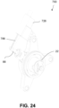
- FIG 24 shows an alternative embodiment 700 of the assembly 20 where the vacuum actuator 26 is replaced by a solenoid 726 that drives actuator rod 786.
- the actuator rod 786 drives the crank 88, which in turn drives the leadscrew 90 and the brake 80, as discussed above.
- a vacuum pressure measuring transducer could be connected to an electronic controller in order to switch the vacuum pump 22 on or off.
- FIG 11 shows an optional, alternative clutch control member 300.
- the clutch control member 300 is similar to the clutch control member 40 but has a radially outer surface 302 which has a lobe 304 on it.
- the lobe 304 has a leading surface 306 that has a progressively increasing distance from the axis of rotation of the clutch control member 300 and a trailing surface 308.
- the actual size of the lobe may be as little as 0.5mm in some embodiments, or it may be larger. It is shown exaggerated in the figures.
- the angular width of the size of the lobe 304 may be any suitable width, such as about 90 degrees.
- the leadscrew 90 can engage and stop the clutch control member 300 in a generally consistent selected angular position each time the leadscrew 90 is employed to stop the clutch control member 300.
- This can be advantageous for several reasons.
- One advantage is that the clutch control member 300 may be connected to the vacuum pump rotor 28 such that, when the clutch control member 300 is stopped in the selected angular position, the vacuum pump rotor 28 is stopped in the generally consistent selected angular rotor position from which there is relatively low resistance to rotor movement during actuation of the vacuum pump 22.
- the position at which the rotor 28 may be stopped each time may be selected so that it is relatively easy to start up the vacuum pump 22 again when needed.
- a 'generally consistent selected angular position' may be any position within a selected range of positions, such as any position within plus or minus about 15 degrees of the position shown in Figure 11 .
- the selected range of positions may be any position within plus or minus about 30 degrees.
- the clutch control member 300 may have any suitable non-round shape so as to have any suitable selected number of lobes 304.
- a generally square shape has four lobes, for example.
- the vacuum actuator 26 moves into position to stop the clutch control member 300 relatively easily.
- the additional braking force that is provided relative to a version with a circular clutch control member means that the clutch control member 300 remains stopped for longer (i.e. thereby delaying the rotation of the clutch control member 300 and the consequent driving of the vacuum pump rotor 28, as compared to the clutch control member 40, as compared to a perfectly circular clutch control member).
- the non-round outer surface of the clutch control member 300 provides setpoint hysteresis to the assembly 20 in that a first degree of vacuum is needed in the vacuum conduit 30 to initiate actuation of the vacuum actuator 26 to stop the clutch control member 300, and a second degree of vacuum that is less strong (i.e. is closer to atmospheric pressure) than the first degree of vacuum is needed to return the vacuum actuator 26 to the position in which the clutch control member 300 is permitted to rotate.
- Setpoint hysteresis can be important for the passively controlled assembly 20 because the vacuum actuator 26 may not be sufficiently precise to operate under a single control setpoint to prevent dithering under conditions close to the setpoint, resulting in assembly instability due to repeated turn-on/turn-off under such conditions.
- Figures 17A and 17B show another means for providing setpoint hysteresis.
- the brake 80 in this embodiment is a hysteretic brake beam 500, such as a bistable spring band.
- the brake beam 500 When in the non-braking position ( Figure 17A ), the brake beam 500 is stable.
- the leadscrew 90 In order to move it to the braking position, the leadscrew 90 has to apply a relatively large amount of force, which causes the brake beam 500 to pass its transition position at which point it quickly moves to its second stable position, (i.e. the braking position shown in Figure 17B ) in which it engages and stops the clutch control member 40 (or 300). Until the brake beam 500 reaches and pass its transition position however, it exerts a relatively high resistance to movement by the leadscrew 90.
- the brake beam 500 may relatively easily return to the non-braking position shown in Figure 17A .
- a first degree of vacuum is needed in the vacuum conduit to initiate actuation of the vacuum actuator 26 to stop the clutch control member 40, 300, and a second degree of vacuum that is less strong (i.e. is closer to atmospheric pressure) than the first degree of vacuum is needed to return the vacuum actuator 26 to the position in which the clutch control member 40, 300 is permitted to rotate.
- any other suitable structure may be provided for providing the aforementioned hysteresis effect that is provided by the embodiments shown in Figures 11 and 17A and 17B .
- the force needed to bring the bistable brake beam 500 from the first stable position to the second stable position may be referred to as the bifurcation force.
- Figure 18 shows another means for providing setpoint hysteresis.
- a restrictor 510 is disposed between a vacuum reservoir 512 and the vacuum actuator 26.
- the restrictor 510 introduces a delay to the length of time the vacuum pump 22 is active so as to ensure that there is more vacuum generated than needed to turn the assembly 20 off - thus generating hysteresis.
- the amount of time delay or hysteresis is dependent on the characteristics of the vacuum pump 22 and the speed at which it is spinning. At higher speeds the restrictor 510 will generate higher hysteresis.
- a check valve 514 can also be installed in parallel to the restrictor 510. This ensures that the time delay does not occur when the pump 22 needs to turn on (air flows towards the actuator), as the check valve opening allows the restrictor 510 to be bypassed, allowing high flow to the actuator.
- setpoint hysteresis can be provided by the electronic control system which can establish turn-on and turn-off pressures.
- FIGs 19-23 show an optionally provided torque limiting clutch 600 ( Figure 19 ) for use in the assembly 20 or similar assembly 20' shown in Figure 23 .
- the torque limiting clutch 600 may be used in conjunction with, or instead of, a means for preventing the vacuum pump 22 from filling with oil when it is not running, examples of which are disclosed below.
- the torque limiting clutch 600 is operatively connected between the camshaft 14 and the rotor 28 ( Figure 3 ) of the vacuum pump 22, to limit torque transfer to the rotor 28 when the clutch 24 is engaged.
- a typical vacuum pump could experience a torque spike upon startup because of the amount of torque needed to drive the rotor to push the oil out of the pump.
- FIG. 21 An example of such a torque spike is shown at 602 in Figure 21 , which shows a torque curve over time, for the vacuum pump 22 without any structure to prevent oil flow into the vacuum pump 22 when it is off, and without any structure to limit torque transfer to the vacuum pump 22.
- the torque spike shown at 604 in Figure 21 is the torque spike that occurs when the torque limiting clutch 600 is provided, with no means to prevent oil flow into the vacuum pump 22 when it is not running.
- this torque spike 604 is much smaller than the torque spike 602.
- the driver shown at 606, is part of the assembly 20 that transfers torque between the camshaft 14 ( Figure 1 ) and the rotor 28 ( Figure 3 ), and therefore the driver 606 may be said to transfer torque between the camshaft 14 and the rotor 28.
- the driver 606 transfers torque from the clutch 24 to the rotor 28 through the torque limiting clutch 600.
- the driver 606 is formed from two components, namely a first driver portion 600a and a second driver portion 606b.
- the first driver portion 606a may be similar to the first driver portion 38a shown in Figure 4A , and may have lugs 71 that engage lug receiving recesses 72 in the carrier 36.
- the first driver portion 606a receives torque from the first end 62 of the wrap spring 25 via the carrier 36.
- the first driver portion 606a has a contact surface 607 thereon that extends generally radially and axially and that engages a first end 608 of the torque limiting clutch 600.
- the torque limiting clutch 600 may itself be a type of wrap spring, and has one or more coils 609 (also referred to as coil 609) that extend generally helically.
- the first end 608 of the torque limiting clutch 600 is a first helical end of the one or more coils 609.
- the torque limiting clutch 600 has a radially inner or outer surface 610 that is frictionally engaged with a complementary radially inner or outer surface 611 of the second driver portion 606b, with a selected amount of preload (i.e. with a selected amount of normal force applied by the surface 610 on the surface 611).
- the surface 610 is a radially inner surface 610 of the coil 609 and the complementary surface 611 is a radially outer surface of the second driver portion 606b.
- the amount of torque that can be transmitted through the torque limiting clutch 600 to the second drive portion 606b depends on several factors including the surface area of contact between the coil 609 and the second driver portion 606b, the coefficient of friction between the coil 609 and the second driver portion 606b, and the normal force with which the coil 609 is engaged with the second driver portion 606b.
- the torque limiting clutch 600 is shown as a 'closing' type of wrap spring clutch. This means that the coil 609 transmits torque through its radially inner surface shown at 610, to the radially outer surface 611 of the second driver portion 606b. However, when torque is transmitted to the torque limiting clutch 600 from the first driver portion 606a, the torque urges the one or more coils 609 to open radially, which causes a reduction of the normal force on the second driver portion 606b.
- increasing torque transfer to the first helical end 608 of the torque limiting clutch 600 drives movement of the first helical end 608 (due to flexure of the coil 609) in a direction that reduces the preload until the surface 610 slips on the complementary surface 611.
- This causes the maximum amount of torque that can transmitted through the connection between the torque limiting clutch 600 and the second driver portion 606b, to decrease.
- the amount of torque transmitted to the torque limiting clutch 600 increases, the magnitude of the normal force applied by the torque limiting clutch 600 on the second driver portion 606b decreases, and so the amount of torque that the torque limiting clutch 600 can transmit to the second driver portion 606b decreases.
- the amount of torque that can be transmitted remains level, dependent on the kinetic coefficient of friction, the contact area and the normal force.
- the value is selected to be low enough to prevent damage to the components transmitting the torque between the camshaft 14 and the vacuum pump rotor 28.
- the value may be selected to be low enough to provide at least a selected fatigue life to these components.
- the value may be set to be high enough to ensure that the vacuum pump 22 empties itself of oil within a selected amount of time so that it can act to generate vacuum as needed. The particular value or range of values that are acceptable will vary depending on the specific application.
- the driver 606 may be operatively connected to the rotor 28 in the same way that the driver 38 ( Figure 8 ) engages the rotor 28, (e.g., by means of a linear slot 74 on the second driver portion 606b, which engages the linear projection 76 on the rotor 28.
- an oil flow path 614 extends through the assembly 20 from a source of oil 616 to the rotor 28 ( Figure 22 ).
- the oil flow path 614 differs from an oil flow path 102 shown in Figure 9A that will be discussed in greater detail below in that the oil flow path 614 does not include a structure, such as a valve, to stop oil flow to the rotor 28, and is instead an open path from the source of oil 616 to the rotor 28.
- a portion of the oil flow path 614 is shown schematically by dashed lines in Figure 23 .
- torque limiting clutch 600 can be applied to an assembly 20 that employs any kind of clutch 24, i.e., clutch 24 does not have to be a wrap spring clutch.
- the vacuum pump 22 may require a flow of oil therein to lubricate the rotor 28 during rotation, as is the case with some rotary vane vacuum pumps, for example. Additionally, oil may be needed in the vacuum pump 22 to help form a seal between vanes and the housing of the pump 22, in order for the pump 22 to generate a stronger vacuum. However, it is beneficial to stop the flow of oil into the vacuum pump 22 when the vacuum pump 22 is not running.
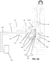
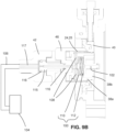
- an oil flow control arrangement is provided, which includes a valve 100 (shown in Figures 9A and 9B ) that stops the flow of oil to the vacuum pump 22 when it is not running ( Figure 9B ) and permits the flow of oil to the vacuum pump 22 when it is running ( Figure 9A ). Additionally, the valve 100 may permit flow to the wrap spring clutch 24 when the vacuum pump 22 is not running. As a further option, the valve 100 may operate without the need for electronic controls.
- the wrap spring clutch 24 is positioned in the engaged position so as to operatively connect the camshaft 14 to the rotor 28 to drive the rotor 28.
- the wrap spring clutch 24 is in the disengaged position wherein the wrap spring clutch 24 operatively disconnects the camshaft 14 from the rotor 28 such that the rotor 28 stops.
- a first oil flow path shown at 102 extends from an oil source 104 (e.g. the vehicle's oil reservoir which is not shown) to the vacuum pump 22.
- the oil source 104 is shown schematically as a simple rectangle and the conduit leading from it to the assembly 20 is shown in dashed lines at 106.
- a second oil flow path 108 extends from the oil source 104 to the wrap spring clutch 24.
- the valve 100 includes a valve member 110 that is positionable in a first position ( Figure 9A ) in which the valve member 110 permits oil flow in the first oil flow path 102, and a second position in which the valve member 110 permits oil flow in the second oil flow path 108.
- the valve member 110 is moved to the first position by driving of the rotor 28 and is moved to the second position by stoppage of the rotor 28. In the example shown, this is achieved by providing a biasing member 112 that applies a biasing force to urge the valve member 110 to the second position, and positioning the valve member 110 in such a way that a vacuum generated by operation of the rotor 28 is sufficient to draw the valve member 110 to the first valve member position against the biasing force applied by the valve member biasing member 112.
- the valve member biasing member 112 is a wave washer or other similar member.
- the valve member biasing member 112 may be positioned, along with the valve member 110 in a chamber 114 defined between the first and second driver portions 38a and 38b.
- the oil can assist in reducing the amount of residual friction that may exist by some small rubbing between the wrap spring 25 and the clutch engagement surface 60 when the wrap spring clutch 24 is in the disengaged position. This reduces the amount of power consumed by the engine 10 when the vacuum pump 22 not being driven.
- the valve member 110 is configured to direct oil flow as described above through suitable aperture and sealing arrangements.
- the valve member 110 When the valve member 110 is in its first position ( Figure 9A ), the valve member is open to the first oil flow path 102 and seals the second oil flow path 108. Conversely, when the valve member 110 is in its second position, the valve member is open to the second oil flow path 108 and seals off the first oil flow path 102.
- the valve member 110 it is possible for the valve member 110 to be configured to permit oil flow to the wrap spring clutch 24 when the valve member 110 is in either of its first and second positions, but to permit oil flow to the vacuum pump 22 only when the valve member 110 is in its first position.
- Figures 9A and 9B relate to a vacuum pump 22 that is driven by the camshaft 14, it will be understood that the vacuum pump 22 could instead be any accessory that operates using oil, and that the camshaft 14, which is driven by the engine 10, could alternatively be any other suitable input member that is driven by any other suitable power source.
- portions of the overall oil circuit (which includes, for example, the oil flow paths 106, 102 and 108) may be provided directly in certain components such as is shown at 117 in the camshaft adapter 42, however some portions may be provided by a separate conduit as shown at 115.
- Suitable seal members 116 e.g. 0-rings are used where needed to maintain an oil seal.
- the first system housing portion 81 may be a separate member that mounts to a housing member 118 for the vacuum pump 22 via a plurality of fasteners (not shown).
- the housing member 118 may also be referred to as a second system housing portion).
- Figure 10 shows a vacuum pump 120 that is integrated with certain other components of the assembly 20 more fully.
- the rotor and the second driver portion are integral with one another and are shown at 202 and may be formed from a single block of material, and the first system housing member 81 and the vacuum pump housing member 118 may together be formed from a single block of material and shown at 204.
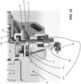
- Figure 12 shows an alternative arrangement for controlling the flow of oil to the vacuum pump 22, in which the leadscrew 90 has an oil control valve engagement cam 310 fixedly connected thereto.
- the cam 310 is engaged with an oil control valve member 312, which is movable between a first valve member position ( Figure 12 ) in which the valve member 312 permits oil flow in the oil flow path (i.e. to the vacuum pump 22), and a second valve member position in which the valve member 312 prevents oil flow in the first oil flow path.
- the oil flow path is shown at 313.
- the oil control valve member 312 is biased towards the second valve member position by a valve member biasing member 314.
- Figures 13A and 13B show the leadscrew 90 in section to show the cam 310 and the valve member 312.
- Figure 13A shows the position of the leadscrew 90 and the cam 310 when there is sufficient vacuum in the conduit 30 ( Figure 3 ) to disconnect the camshaft 14 from the vacuum pump 22.
- the cam 310 is in a valve member closure position, which permits the valve member biasing member 314 to move the valve member 312 to the second valve member position to prevent oil flow to the vacuum pump 22.
- the vacuum actuator 26 causes the leadscrew 90 to rotate, which drives the cam 310 to the position shown in Figure 13B , which, in turn moves the valve member 312 to the first valve member position.
- Figures 14 , 15 , 16A and 16B show another alternative oil flow control arrangement.
- the driver includes a first driver portion 400a and a second driver portion 400b that is rotationally movable relative to the first driver portion 400a.
- the first driver portion 400a is similar to the first driver portion 38a, and receives torque from the wrap spring clutch 24 for transfer to the vacuum pump rotor 28.
- the first driver portion 400a has a first oil flow path 402 which has a first end 402a, and a second end 402b that is fluidically connected to an oil source (e.g. oil source 104 shown in Figures 9A and 9B ).
- the second driver portion 400b has a second oil flow path 404 therethrough, which has a first end 404a, and a second end 404b that is fluidically connected to the vacuum pump 22.
- a first seal surface 406 is provided on the first driver portion 400a and a second seal surface 408 is provided on the second driver portion 400b.
- the first sealing surface 406 is engageable with the second sealing surface 408 to prevent oil flow through the second oil flow path 404 into the vacuum pump 22.
- the second seal surface 408 surrounds the first end 404a of the second oil flow path 404 and the first seal surface 402 is a generally planar surface on a rubber member 410.
- the first driver portion 400a is rotatable relative to the second driver portion 400b between a first, sealing position ( Figure 16A ), in which the first sealing surface 406 is engaged with the second sealing surface 408 to prevent oil flow through the second oil flow path 404 into the vacuum pump 22, and a second, oil flow position ( Figure 16B ) in which the first sealing surface 406 is disengaged with the second sealing surface 408 to fluidically connect the first and second oil flow paths 402 and 404 so as to permit oil flow through the second oil flow path 404 into the vacuum pump 22.
- a first, sealing position Figure 16A
- Figure 16B in which the first sealing surface 406 is disengaged with the second sealing surface 408 to fluidically connect the first and second oil flow paths 402 and 404 so as to permit oil flow through the second oil flow path 404 into the vacuum pump 22.
- seal surfaces 406 and 408 are free of any portions that extend purely in the radial plane, which is the plane that is perpendicular to the axis of rotation Accm of the driver portions 400a and 400b.
- a driver biasing member 412 is provided between the first and second driver portions 400a and 400b, which biases the first biasing member 400a towards the sealing position.
- the driver biasing member 412 maintains engagement between the seal surfaces 406 and 408 to prevent oil flow into the vacuum pump 22.
- the driver portion 400a when there is insufficient vacuum in the vacuum conduit 30, the driver portion 400a is driven to rotate by the camshaft 14 (via the wrap spring clutch 24). Due to one or more of: inertia in the vacuum pump rotor 28, frictional resistance to rotation of the rotor 28 and resistance to rotation due to any load engaged by the rotor (i.e. air in the vacuum pump to be evacuated), the second driver portion 400b will resist movement. As a result, the first driver portion 400a will rotate relative to the second driver portion 400b, thereby disengaging the seal surfaces 406 and 408 from one another, which in turn permits oil flow immediately into the vacuum pump 22.
- the driver biasing member 412 has a relatively low spring rate, and easily permits relative movement between the first and second driver portions 400a and 400b.
- a first drive torque transfer surface 414 ( Figures 15 on the first driver portion 400a will engage a second drive torque transfer surface 416 on the second driver portion 400b.
- any subsequent amount of drive torque is transferred from the first driver portion 400a to the second driver portion 400b via the drive torque transfer surfaces 414 and 416.
- a sleeve 400c that effectively forms part of the second driver portion 400b may be provided to support the spring and to align the first and second driver portions 400a and 400b relative to one another.
- the vacuum pump rotor 28 and vacuum pump 22 may alternatively be any accessory that incorporates a rotor that is to be driven by the driver portion 400b.
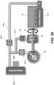
- FIG 25 shows an example of a vehicular vacuum system 800.
- the engine 10 is connected to a brake booster 802 via a first conduit 804 in which a check valve 806 can be installed.
- the engine 10 includes an intake manifold 811 that provides the primary source of vacuum. Any of the embodiments of assembly 20 can be connected to the engine 10 and the brake booster 802.
- the clutch 24 can be connected to an engine shaft such as a camshaft or any other suitable rotary power takeoff provided by the engine.
- the vacuum pump 22 is connected to the first conduit 804 (upstream of the check valve 806, if any) via a second conduit 808.
- a check valve 810 can be installed in the second conduit 808.
- the vacuum actuator 26 is also connected to the first conduit 804 (upstream of the check valves 806, 810, if any) via a third conduit 814.
- the intake manifold 811 provided sufficient vacuum for the brake booster 802 about 94-97% of the time in standardized test cycles, leaving the assembly 20 with a 36% duty cycle. This result yielded a fuel efficiency saving estimate of about 1.5% over a non-clutched vacuum pump. The savings will, of course, depend on the specific application.
Landscapes
- Engineering & Computer Science (AREA)
- General Engineering & Computer Science (AREA)
- Mechanical Engineering (AREA)
- Physics & Mathematics (AREA)
- Electromagnetism (AREA)
- Chemical & Material Sciences (AREA)
- Combustion & Propulsion (AREA)
- Hydraulic Clutches, Magnetic Clutches, Fluid Clutches, And Fluid Joints (AREA)
- Valves And Accessory Devices For Braking Systems (AREA)
- Compressors, Vaccum Pumps And Other Relevant Systems (AREA)
Description
- This disclosure generally relates to mechanical clutches for transmitting power between two rotary members, and more particularly, to a clutched vacuum pump assembly and system. Further relevant Prior Art is described in
US 9 068 603 B2 WO 2010/054487 A1 andWO 2013/067621 A1 . - It is known to transmit power between an internal combustion engine and a shaft of an accessory device to power the device. An example is an automotive vacuum pump or water pump. In some engines it can be desirable to switch the vacuum pump or water pump on or off based on demand. For example, switching the vacuum pump off when it is not needed can increase fuel efficiency. Electrical pumps have conventionally been used to implement this function; however electrical pumps can be more costly than mechanical pumps and suffer energy losses as power is converted between mechanical-electrical-mechanical work.
- Clutched mechanical pumps are known. For example,
US 8,387,767 ,EP 1,887,224 ,US 9,068,603 US 9,267,552 US 2016/0121871 ,US 9,333,963 US 2015/0251644 andWO 2015/090415 disclose clutched vacuum pump systems using various types of clutches such as electromagnetic, magneto-rheological and hydraulic clutches. - A more elegant clutched vacuum pump assembly and related system may be desirable.
- In accordance with the present invention, it is provided a vacuum generation system having the features defined in claim 1. Further a method of operating a vacuum system, which method has the features is defined in
claim 12 is provided. Further preferred embodiments can be found in the dependent claims. - The foregoing and other aspects of the invention will be better appreciated having regard to the attached drawings, wherein:
-
Figure 1 is a schematic view of an engine with an endless drive arrangement including a system in accordance with an embodiment of the present disclosure; -
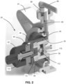
Figure 2 is a sectional perspective view of a vacuum assembly shown inFigure 1 ; -
Figure 3 is another perspective view of the assembly shown inFigure 1 , showing a vacuum actuator in a high-pressure position; -
Figure 3A is a sectional elevation view of the vacuum actuator shown inFigure 3 in a low-pressure position; -
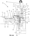
Figure 4A is a sectional elevation view of the assembly shown inFigure 2 in a first position; -
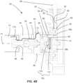
Figure 4B is a sectional elevation view of the assembly shown inFigure 2 in a second position; -
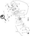
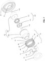
Figure 5 is a perspective exploded view of the assembly shown inFigure 2 ; -
Figure 6 is a magnified perspective exploded view of a portion of the assembly shown inFigure 5 ; -
Figure 7 is a magnified perspective exploded view of another portion of the assembly shown inFigure 5 ; -
Figure 8 is another perspective exploded view of the assembly shown inFigure 2 ; -
Figure 9A is a sectional side elevation view of the assembly in the position shown inFigure 4A , illustrating an oil flow path through the assembly when in this position; -
Figure 9B is a sectional side elevation view of the assembly in the position shown inFigure 4B , illustrating an oil flow path through the assembly when in this position; and -
Figure 10 is a sectional side elevation view of an alternative embodiment of the assembly; -
Figure 11 is a sectional end elevation view of another alternative embodiment of the assembly; -
Figure 12 is a sectional perspective view of another alternative embodiment of the assembly; -
Figure 13A is a sectional end view of a leadscrew when the vacuum actuator is in a low-pressure position; -
Figure 13A is a sectional end view of the leadscrew shown inFigure 13A when the vacuum actuator is in a high-pressure position; -
Figure 14 is a sectional side elevation view of an oil flow control arrangement alternative to that shown inFigures 9A and9B ; -
Figure 15 is a perspective exploded view of the oil flow control arrangement shown inFigure 14 ; -
Figure 16A is a sectional perspective view of the assembly showing the oil flow control arrangement shown inFigure 14 in a sealing position to prevent oil flow therethrough; -
Figure 16B is a sectional perspective view of the assembly showing the oil flow control arrangement shown inFigure 14 in an oil flow position to prevent oil flow therethrough; -
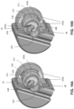
Figure 17A is a sectional end view of an alternative braking structure that employs a hysteretic spring band, in a non-braking position; -
Figure 17B is a sectional end view of the alternative braking structure shown inFigure 17A showing the hysteretic spring band in a braking position; -
Figure 18 is a schematic view of another alternative structure for generating a hysteresis effect during operation of the vacuum actuator, which includes a flow restriction element; -
Figure 19 is a perspective exploded view of an optional torque limiting clutch that can be used in the assembly shown inFigure 2 ; -
Figure 20 is another exploded view of the optional torque limiting clutch shown inFigure 19 ; -
Figure 21 is a graph illustrating a torque spike that occurs when a vacuum pump is started while full of oil with and without the torque limiting clutch shown inFigures 19 and 20 ; -
Figure 22 is a sectional perspective view of the assembly shown inFigure 2 , with the torque limiting clutch shown inFigures 19 and 20 ; -
Figure 23 is a sectional side elevation view of the assembly shown inFigure 2 , with the torque limiting clutch shown inFigures 19 and 20 ; -
Figure 24 is a front perspective view of an alternative embodiment of the assembly shown inFigure 2 , in which a solenoid replaces the vacuum actuator; and -
Figure 25 is a system block diagram of a vacuum system application. -
Figure 1 is a schematic view of avehicular engine 10. Theengine 10 includes acrankshaft 12 that drives at least onecamshaft 14 via anendless drive member 16, which may be, for example, a timing belt or a timing chain. Thecamshaft 14 is shown with twocams 18 thereon, for illustrative purposes only. It will be understood that the actual number ofcams 18 on thecamshaft 14 will depend on the number of cylinders the engine has, the number of valves per cylinder and the total number of camshafts being employed to control the opening and closing of the valves, as well as other possible factors. Theengine 10 is shown in a simplified format for the purposes of avoiding extraneous detail. -
Figure 1 shows (in schematic form) anassembly 20 for selectively generating vacuum using theengine 10 as a motive source. In some embodiments, theassembly 20 consumes less energy to generate vacuum than a conventional mechanical vacuum pump because theassembly 20 only generates vacuum when the pressure in a selected conduit is above a selected threshold. Referring additionally toFigures 2-3 , theassembly 20 includes, in some embodiments, a vacuum pump 22 (Figure 3 ), a clutch 24 (Figure 2 ) operatively connected to thepump 22, and a vacuum actuator 26 (shown schematically inFigure 3 ) operatively connected to theclutch 24. - As seen in
Figure 3 , thevacuum pump 22 has arotor 28 that is rotatable to generate a vacuum. In the example shown, thevacuum pump 22 is a rotary vane vacuum pump, however, it is simply one example of a suitable vacuum pump. Alternatively, any other type of vacuum pump that employs a rotor of some kind may be used. - The
clutch 24 is controllable to operatively connect an engine rotary power take-off such as thecamshaft 14, which is driven by theengine 10, to therotor 28, as described in greater detail below. - The vacuum actuator 26 (
Figure 3 ) is connected to avacuum conduit 30 in the vehicle. Thevacuum actuator 26 is movable, based on air pressure in thevacuum conduit 30, between a low-pressure position (shown inFigure 3A ) in which thevacuum actuator 26 controls theclutch 24 to operatively disconnect thecamshaft 14 and therotor 28, and a high-pressure position (shown inFigure 3 ) in which thevacuum actuator 26 controls theclutch 24 to operatively connect thecamshaft 14 to therotor 28. - Referring additionally to
Figures 4A ,4B and5-7 , theassembly 20 may further include a rotary input member such asconnector 32, acarrier 36, adriver 38, and aclutch control member 40. Theconnector 32 extends from thecamshaft 14 and includes acamshaft adapter 42, afirst transfer member 44 and asecond transfer member 46. Thecamshaft adapter 42 mounts fixedly to thecamshaft 14 in any suitable way. For example, thecamshaft adapter 42 may include asplined end 48 that engages a complementarilysplined aperture 50 in thecamshaft 14. Thefirst transfer member 44 includes first and secondlinear projections projections second slots camshaft adapter 42 and thesecond transfer member 46 respectively. Theprojections slots assembly 20 to tolerate some amount of misalignment between the axis of rotation of therotor 28 of thevacuum pump 22 and the axis of rotation of thecamshaft 14. The axes are shown at AI and A2 respectively. The present disclosure employs terms such as 'axial', 'radial' and 'circumferential' in general reference to the axes AI and A2, which are expected to be at least substantially collinear. - The clutch 24 may be embodied via a
wrap spring 25 and hence referred to as awrap spring clutch 24 in such embodiments. - As seen in
Fig. 7 , thewrap spring 25 has afirst end 62 and asecond end 64 and a plurality ofcoils 66 extending between the first and second ends 62 and 64. The outer surface of thecoils 66 present anengagement surface 68 that is engageable with a clutch engagement surface 60 (seen inFigures 4A and4B ) of thesecond transfer member 46. In the illustrated embodiment the wrap clutch has an "opening spring" configuration wherein theengagement surface 68 is a radially outer surface of thecoils 66 and theengagement surface 60 is a radially inner surface of thesecond transfer member 46; however in alternative embodiments the wrap clutch can have a "closing spring" configuration whereinengagement surface 68 is a radially inner surface of thecoils 66 and theengagement surface 60 is a radially outer surface of thesecond transfer member 46. - As seen in
Figure 7 , thefirst end 62 of thewrap spring 25 is received in aslot 70 in thecarrier 36. Thecarrier 36 may be a polymeric member that assists in transferring force from thefirst end 62 of thewrap spring 25 into one of twolugs 71 on thedriver 38. For example, thecarrier 36 may have lug receiving apertures (a small portion of each of which can be seen in at 72 inFigure 7 ) that snugly receive thelugs 71. Thecarrier 36 may have theslot 70 positioned so that when thelugs 71 are received in thelug receiving apertures 72, thecarrier 36 snugly holds the tip of thefirst end 62 in direct engagement with one of thelugs 71. In the illustrated embodiment thecarrier 36 itself does not directly transfer torque but it will be understood that thecarrier 36 can have features which engage thelugs 71 to assist in torque transfer. - A
carrier retainer 73, such as a metallic member, can be press-fit on the driver 38 (which may be metallic) to retain thecarrier 36 in position to assist in the transfer of torque between thefirst end 62 of thewrap spring 25 and thedriver 38. - The
driver 38 itself may be made from two elements, including afirst driver portion 38a and asecond driver portion 38b, which may be press-fit into thefirst driver portion 38a so as to be fixedly connected thereto. - The
driver 38 transfers torque from thefirst end 62 of thewrap spring 25 to therotor 28. As shown in the partial exploded view inFigure 8 , thesecond driver portion 38b may have alinear slot 74, similar to slot 56 in thesecond transfer member 46, which engages alinear projection 76 on therotor 28. - The
wrap spring clutch 24 can be set in an engaged or driving position (Figure 4A ) in which thewrap spring clutch 24 operatively connects thecamshaft 14 to therotor 28 or set in a disengaged or non-driving position (Figure 4B ) in which thewrap spring clutch 24 operatively disconnects thecamshaft 14 from therotor 28. In the engaged position thewrap spring 25 is essentially locked against, and rotates together with, theclutch engagement surface 60 of thesecond transfer member 46. As thesecond transfer member 46 is drivingly connected to thecamshaft 14, thefirst end 62 of thewrap spring clutch 24 may be said to be driven by thecamshaft 14 when thewrap spring clutch 24 is in the engaged position. In the disengaged position, as discussed in greater detail below, thewrap spring 25 disengages from theclutch engagement surface 60 of thesecond transfer member 46 whereby thewrap spring 25 does not rotate in conjunction with thesecond transfer member 46. -
Figures 4A and4B show torque flow paths at 77A and 77B, respectively, to illustrate the elements that are driven by thecamshaft 14 when thewrap spring clutch 24 is in the engaged position (Figure 4A ) and the disengaged position (Figure 4B ). As can be seen, in the engaged position torque is transferred from thecamshaft 14 through theconnector 32, into thewrap spring 25, into thedriver 38 and therefore to the rotor 28 (not shown inFigure 4A ). In the dis-engaged position, torque is transferred from thecamshaft 14 and into theconnector 32, ending at thesecond transfer member 46. - The
wrap spring clutch 24 may be biased towards one of the engaged and disengaged positions. In the example shown, thewrap spring clutch 24 is biased to the engaged position by virtue of thewrap spring 25 having a nominal resting diameter larger than the inner diameter of theclutch engagement surface 60 of thesecond transfer member 46. Thus, thewrap spring clutch 24 defaults to the engaged position. - As seen in
Figure 7 , theclutch control member 40 holds thesecond end 64 of thewrap spring clutch 24. Theclutch control member 40 may be a disc that has aslot 78 that holds thesecond end 64 of thewrap spring 25. Thesecond end 64 may be bent into an axially extending tang. - As seen in
Figure 4A ,4B and5 , abrake 80 interacts with theclutch control member 40. Thebrake 80 can be set to a non-braking position (Figure 4A ) and a braking position (Figure 4B ). Thebrake 80 may be a small metallic strip that extends from a stationary member 81 (e.g. a first housing portion of the assembly 20) and which engages a radially outer surface 82 (that may be referred to as a brake engagement surface 82) of theclutch control member 40. When set to the braking position, thebrake 80 contacts and begins to slow theclutch control member 40 relative to thecamshaft 14 so as to retard the angular position of thesecond end 64 of thewrap spring 25 relative to thefirst end 62 thereof, causing thewrap spring 25 to coil more tightly and disengage from theclutch engagement surface 60 of thesecond transfer member 46, placing thewrap spring clutch 24 in the disengaged position. Thewrap spring 25 will remain disengaged so long as thebrake 80 is applied. In the non-braking position, thebrake 80 does not interfere with the relative angular positions of the first and second ends 62, 64 of thewrap spring 35, enabling thewrap spring 25 to remain in the engaged position. - The
brake 80 may act as a leaf spring and may be biased by its own resiliency to the non-braking position. - The
vacuum actuator 26 is operatively connected to thebrake 80 such that movement of thevacuum actuator 26 to the low-pressure position places thebrake 80 in the braking position and thewrap spring clutch 24 in the disengaged position. Movement of thevacuum actuator 26 to the high-pressure position places thebrake 80 in the nonbraking position and thewrap spring clutch 24 in the engaged position. - As seen in
Figures 2-4 , in the present example thevacuum actuator 26 includes avacuum actuator housing 83, adiaphragm 84, a vacuumactuator biasing member 85 and anactuator rod 86 that operatively connects the vacuum actuator to a crank 88. Thecrank 88 is connected to aleadscrew 90 that engages athread 92 in a stationary member such as the firstsystem housing portion 81. Theleadscrew 90 engages thebrake 80. When thevacuum actuator 26 is in the high-pressure position (Figure 3 ), theleadscrew 90 is retracted, enabling thebrake 80 to be in the non-braking position. As a result, theclutch control member 40 rotates with thewrap spring 25, which rotates with thecamshaft 14. When thevacuum actuator 26 moves to the low-pressure position (Figure 3A ), theleadscrew actuator 86 moves thecrank 88 in a first direction through a selected arc, which advances theleadscrew 90 to engage and drive thebrake 80 into engagement with theclutch control member 40 such that thebrake 80 retards rotation of theclutch control member 40 relative to thecamshaft 14. Because theclutch control member 40 holds thesecond end 64 of thewrap spring 25, retarding theclutch control member 40 causes thewrap spring 25 to contract radially, bringing thewrap spring clutch 24 out of engagement with thesecond transfer member 46 and operatively disconnecting thecamshaft 14 and therotor 28. - Movement of the
vacuum actuator 26 back to the high-pressure position causes theactuator rod 86 to drive thecrank 88 back in a second direction through the selected arc, which retracts theleadscrew 90, which in turn permits thebrake 80 to lift away from theclutch control member 40. As a result, thewrap spring 25 expands under its own restoring force and engages thesecond transfer member 46. - Thus, it will be understood from the foregoing that when the pressure in the
vacuum conduit 30 is sufficiently low, thevacuum actuator 26 moves to the low-pressure position (Figure 3A ), disconnecting thevacuum pump 22. Thevacuum conduit 30 may be connected to one or more sources of vacuum in a vehicle, such as to a brake booster, a turbocharger wastegate, or the intake manifold of the engine, and when the pressure in thevacuum conduit 30 becomes too high, thevacuum actuator 26 moves to the highpressure position (Figure 3 ), thereby activating thevacuum pump 22 so as to generate vacuum. In some embodiments, thevacuum pump 22 is connected to thevacuum conduit 30 and therefore generates vacuum in thatconduit 30. As a result, thevacuum pump 22 itself will generate vacuum until there is sufficient vacuum in theconduit 30 that the vacuum actuator moves back to the position shown inFigure 3A , which will cause stoppage of thepump 22. Thus, theassembly 20 automatically activates and deactivates thevacuum pump 22 based on the level of vacuum in thevacuum conduit 30, precluding the need for electronic controls. - In the embodiments described herein, it will be noted that, in the event of a failure of the
vacuum actuator 26 or any components that act between thevacuum actuator 26 and the clutch control member, thevacuum pump 22 will be driven by thecamshaft 14, so as to ensure that there is always sufficient vacuum even in the event of a failure. -
Figure 24 shows analternative embodiment 700 of theassembly 20 where thevacuum actuator 26 is replaced by asolenoid 726 that drivesactuator rod 786. Theactuator rod 786 drives thecrank 88, which in turn drives theleadscrew 90 and thebrake 80, as discussed above. For control purposes a vacuum pressure measuring transducer could be connected to an electronic controller in order to switch thevacuum pump 22 on or off. -
Figure 11 shows an optional, alternativeclutch control member 300. Theclutch control member 300 is similar to theclutch control member 40 but has a radiallyouter surface 302 which has alobe 304 on it. As theclutch control member 300 rotates in a certain direction (shown at 305 inFigure 11 ) thelobe 304 has aleading surface 306 that has a progressively increasing distance from the axis of rotation of theclutch control member 300 and a trailingsurface 308. The actual size of the lobe (radially) may be as little as 0.5mm in some embodiments, or it may be larger. It is shown exaggerated in the figures. The angular width of the size of thelobe 304 may be any suitable width, such as about 90 degrees. By providing thelobe 304, theleadscrew 90 can engage and stop theclutch control member 300 in a generally consistent selected angular position each time theleadscrew 90 is employed to stop theclutch control member 300. This can be advantageous for several reasons. One advantage is that theclutch control member 300 may be connected to thevacuum pump rotor 28 such that, when theclutch control member 300 is stopped in the selected angular position, thevacuum pump rotor 28 is stopped in the generally consistent selected angular rotor position from which there is relatively low resistance to rotor movement during actuation of thevacuum pump 22. In other words, the position at which therotor 28 may be stopped each time may be selected so that it is relatively easy to start up thevacuum pump 22 again when needed. A 'generally consistent selected angular position' may be any position within a selected range of positions, such as any position within plus or minus about 15 degrees of the position shown inFigure 11 . Alternatively, the selected range of positions may be any position within plus or minus about 30 degrees. - The
clutch control member 300 may have any suitable non-round shape so as to have any suitable selected number oflobes 304. A generally square shape has four lobes, for example. - As the
leadscrew 90 brings thebrake 80 into engagement with theouter surface 302 of theclutch control member 300, a wedging effect occurs as the leadingsurface 306 of thelobe 304 engages thebrake 80, which causes a greater amount of braking force to be applied to theclutch control member 300 than would be applied if theouter surface 302 were perfectly circular. - As a result of the wedging effect by the non-round
clutch control member 300, thevacuum actuator 26 moves into position to stop theclutch control member 300 relatively easily. Additionally, the additional braking force that is provided relative to a version with a circular clutch control member means that theclutch control member 300 remains stopped for longer (i.e. thereby delaying the rotation of theclutch control member 300 and the consequent driving of thevacuum pump rotor 28, as compared to theclutch control member 40, as compared to a perfectly circular clutch control member). Consequently, the non-round outer surface of theclutch control member 300 provides setpoint hysteresis to theassembly 20 in that a first degree of vacuum is needed in thevacuum conduit 30 to initiate actuation of thevacuum actuator 26 to stop theclutch control member 300, and a second degree of vacuum that is less strong (i.e. is closer to atmospheric pressure) than the first degree of vacuum is needed to return thevacuum actuator 26 to the position in which theclutch control member 300 is permitted to rotate. - Setpoint hysteresis can be important for the passively controlled
assembly 20 because thevacuum actuator 26 may not be sufficiently precise to operate under a single control setpoint to prevent dithering under conditions close to the setpoint, resulting in assembly instability due to repeated turn-on/turn-off under such conditions. -
Figures 17A and 17B show another means for providing setpoint hysteresis. As can be seen, thebrake 80 in this embodiment is ahysteretic brake beam 500, such as a bistable spring band. When in the non-braking position (Figure 17A ), thebrake beam 500 is stable. In order to move it to the braking position, theleadscrew 90 has to apply a relatively large amount of force, which causes thebrake beam 500 to pass its transition position at which point it quickly moves to its second stable position, (i.e. the braking position shown inFigure 17B ) in which it engages and stops the clutch control member 40 (or 300). Until thebrake beam 500 reaches and pass its transition position however, it exerts a relatively high resistance to movement by theleadscrew 90. As is the case with certain bistable devices (an example of which is a snap bracelet), thebrake beam 500 may relatively easily return to the non-braking position shown inFigure 17A . As a result, a first degree of vacuum is needed in the vacuum conduit to initiate actuation of thevacuum actuator 26 to stop theclutch control member vacuum actuator 26 to the position in which theclutch control member - Any other suitable structure may be provided for providing the aforementioned hysteresis effect that is provided by the embodiments shown in
Figures 11 and17A and 17B . The force needed to bring thebistable brake beam 500 from the first stable position to the second stable position may be referred to as the bifurcation force. -
Figure 18 shows another means for providing setpoint hysteresis. In this embodiment, arestrictor 510 is disposed between avacuum reservoir 512 and thevacuum actuator 26. Therestrictor 510 introduces a delay to the length of time thevacuum pump 22 is active so as to ensure that there is more vacuum generated than needed to turn theassembly 20 off - thus generating hysteresis. The amount of time delay or hysteresis is dependent on the characteristics of thevacuum pump 22 and the speed at which it is spinning. At higher speeds therestrictor 510 will generate higher hysteresis. A check valve 514 can also be installed in parallel to therestrictor 510. This ensures that the time delay does not occur when thepump 22 needs to turn on (air flows towards the actuator), as the check valve opening allows the restrictor 510 to be bypassed, allowing high flow to the actuator. - In embodiments where the
assembly 20 utilizes an electrical actuator such as a solenoid to drive theleadscrew 90 andbrake 80, setpoint hysteresis can be provided by the electronic control system which can establish turn-on and turn-off pressures. -
Figures 19-23 show an optionally provided torque limiting clutch 600 (Figure 19 ) for use in theassembly 20 or similar assembly 20' shown inFigure 23 . The torque limiting clutch 600 may be used in conjunction with, or instead of, a means for preventing thevacuum pump 22 from filling with oil when it is not running, examples of which are disclosed below. Thetorque limiting clutch 600 is operatively connected between thecamshaft 14 and the rotor 28 (Figure 3 ) of thevacuum pump 22, to limit torque transfer to therotor 28 when the clutch 24 is engaged. A typical vacuum pump could experience a torque spike upon startup because of the amount of torque needed to drive the rotor to push the oil out of the pump. An example of such a torque spike is shown at 602 inFigure 21 , which shows a torque curve over time, for thevacuum pump 22 without any structure to prevent oil flow into thevacuum pump 22 when it is off, and without any structure to limit torque transfer to thevacuum pump 22. By contrast, providing the torque limiting clutch 600 on thevacuum pump 22 limits the amount of torque transferred to thevacuum pump 22. The torque spike shown at 604 inFigure 21 is the torque spike that occurs when thetorque limiting clutch 600 is provided, with no means to prevent oil flow into thevacuum pump 22 when it is not running. As can be seen, thistorque spike 604 is much smaller than thetorque spike 602. As a result of the lower torque being transferred to thevacuum pump 22, it will take slightly longer to drive the oil out from thevacuum pump 22 during pump startup through the torque limiting clutch 600 but this should not have a deleterious effect in practice. - In the embodiment shown in
Figures 19-23 , the driver, shown at 606, is part of theassembly 20 that transfers torque between the camshaft 14 (Figure 1 ) and the rotor 28 (Figure 3 ), and therefore thedriver 606 may be said to transfer torque between thecamshaft 14 and therotor 28. In the embodiment shown inFigures 19-23 , thedriver 606 transfers torque from the clutch 24 to therotor 28 through thetorque limiting clutch 600. More specifically, thedriver 606 is formed from two components, namely a first driver portion 600a and asecond driver portion 606b. Thefirst driver portion 606a may be similar to thefirst driver portion 38a shown inFigure 4A , and may havelugs 71 that engagelug receiving recesses 72 in thecarrier 36. Thefirst driver portion 606a receives torque from thefirst end 62 of thewrap spring 25 via thecarrier 36. Thefirst driver portion 606a has acontact surface 607 thereon that extends generally radially and axially and that engages afirst end 608 of thetorque limiting clutch 600. The torque limiting clutch 600 may itself be a type of wrap spring, and has one or more coils 609 (also referred to as coil 609) that extend generally helically. Thefirst end 608 of thetorque limiting clutch 600 is a first helical end of the one ormore coils 609. - The
torque limiting clutch 600 has a radially inner orouter surface 610 that is frictionally engaged with a complementary radially inner orouter surface 611 of thesecond driver portion 606b, with a selected amount of preload (i.e. with a selected amount of normal force applied by thesurface 610 on the surface 611). In the embodiment shown, thesurface 610 is a radiallyinner surface 610 of thecoil 609 and thecomplementary surface 611 is a radially outer surface of thesecond driver portion 606b. The amount of torque that can be transmitted through the torque limiting clutch 600 to thesecond drive portion 606b depends on several factors including the surface area of contact between thecoil 609 and thesecond driver portion 606b, the coefficient of friction between thecoil 609 and thesecond driver portion 606b, and the normal force with which thecoil 609 is engaged with thesecond driver portion 606b. - As can be seen, the
torque limiting clutch 600 is shown as a 'closing' type of wrap spring clutch. This means that thecoil 609 transmits torque through its radially inner surface shown at 610, to the radiallyouter surface 611 of thesecond driver portion 606b. However, when torque is transmitted to the torque limiting clutch 600 from thefirst driver portion 606a, the torque urges the one ormore coils 609 to open radially, which causes a reduction of the normal force on thesecond driver portion 606b. In other words, increasing torque transfer to the firsthelical end 608 of the torque limiting clutch 600 drives movement of the first helical end 608 (due to flexure of the coil 609) in a direction that reduces the preload until thesurface 610 slips on thecomplementary surface 611. This, in turn, causes the maximum amount of torque that can transmitted through the connection between thetorque limiting clutch 600 and thesecond driver portion 606b, to decrease. As the amount of torque transmitted to the torque limiting clutch 600 increases, the magnitude of the normal force applied by the torque limiting clutch 600 on thesecond driver portion 606b decreases, and so the amount of torque that the torque limiting clutch 600 can transmit to thesecond driver portion 606b decreases. There is a point at which the torque transmitted to the torque limiting clutch 600 by thefirst driver portion 606a equals the amount of torque that it can transmit to thesecond driver portion 606b, and at that point, slippage occurs between thetorque limiting clutch 600 and thesecond driver portion 606b. Once there is slippage, the frictional resistance force between thetorque limiting clutch 600 and thesecond driver portion 606b levels off based on the kinetic coefficient of friction between them. This resistance force effectively limits the amount by which thecoil 609 will open when torque is inputted to it from thefirst driver portion 606a. Up until there is slippage, an increase in the amount of torque that is inputted to the torque limiting clutch 600 from thefirst driver portion 606a is met with an increase in the amount of frictional resistance in reaction to the increased torque. Once there is slippage however, if an attempt is made to increase the torque inputted to thetorque limiting clutch 600, it is met with increased slippage, as opposed to an increased resistance force, and so there is no corresponding increase in the amount by which thetorque limiting clutch 600 opens. Thus, once this slippage occurs the amount of torque that can be transmitted remains level, dependent on the kinetic coefficient of friction, the contact area and the normal force. As a result, the amount of torque that can be transmitted through the interface between thecoil 609 and thesecond driver portion 606b is limited to a selected value. The value is selected to be low enough to prevent damage to the components transmitting the torque between thecamshaft 14 and thevacuum pump rotor 28. The value may be selected to be low enough to provide at least a selected fatigue life to these components. The value may be set to be high enough to ensure that thevacuum pump 22 empties itself of oil within a selected amount of time so that it can act to generate vacuum as needed. The particular value or range of values that are acceptable will vary depending on the specific application. - Referring to
Figures 22 and23 , thedriver 606 may be operatively connected to therotor 28 in the same way that the driver 38 (Figure 8 ) engages therotor 28, (e.g., by means of alinear slot 74 on thesecond driver portion 606b, which engages thelinear projection 76 on therotor 28. - As can be seen in
Figure 23 in particular, anoil flow path 614 extends through theassembly 20 from a source ofoil 616 to the rotor 28 (Figure 22 ). Theoil flow path 614 differs from anoil flow path 102 shown inFigure 9A that will be discussed in greater detail below in that theoil flow path 614 does not include a structure, such as a valve, to stop oil flow to therotor 28, and is instead an open path from the source ofoil 616 to therotor 28. A portion of theoil flow path 614 is shown schematically by dashed lines inFigure 23 . - It should be appreciated that the torque limiting clutch 600 can be applied to an
assembly 20 that employs any kind ofclutch 24, i.e., clutch 24 does not have to be a wrap spring clutch. - In some embodiments, the
vacuum pump 22 may require a flow of oil therein to lubricate therotor 28 during rotation, as is the case with some rotary vane vacuum pumps, for example. Additionally, oil may be needed in thevacuum pump 22 to help form a seal between vanes and the housing of thepump 22, in order for thepump 22 to generate a stronger vacuum. However, it is beneficial to stop the flow of oil into thevacuum pump 22 when thevacuum pump 22 is not running. In some embodiments, an oil flow control arrangement is provided, which includes a valve 100 (shown inFigures 9A and9B ) that stops the flow of oil to thevacuum pump 22 when it is not running (Figure 9B ) and permits the flow of oil to thevacuum pump 22 when it is running (Figure 9A ). Additionally, thevalve 100 may permit flow to thewrap spring clutch 24 when thevacuum pump 22 is not running. As a further option, thevalve 100 may operate without the need for electronic controls. - In
Figure 9A thewrap spring clutch 24 is positioned in the engaged position so as to operatively connect thecamshaft 14 to therotor 28 to drive therotor 28. InFigure 9B , thewrap spring clutch 24 is in the disengaged position wherein thewrap spring clutch 24 operatively disconnects thecamshaft 14 from therotor 28 such that therotor 28 stops. - A first oil flow path shown at 102 extends from an oil source 104 (e.g. the vehicle's oil reservoir which is not shown) to the
vacuum pump 22. Theoil source 104 is shown schematically as a simple rectangle and the conduit leading from it to theassembly 20 is shown in dashed lines at 106. A secondoil flow path 108 extends from theoil source 104 to thewrap spring clutch 24. - The
valve 100 includes avalve member 110 that is positionable in a first position (Figure 9A ) in which thevalve member 110 permits oil flow in the firstoil flow path 102, and a second position in which thevalve member 110 permits oil flow in the secondoil flow path 108. Thevalve member 110 is moved to the first position by driving of therotor 28 and is moved to the second position by stoppage of therotor 28. In the example shown, this is achieved by providing a biasingmember 112 that applies a biasing force to urge thevalve member 110 to the second position, and positioning thevalve member 110 in such a way that a vacuum generated by operation of therotor 28 is sufficient to draw thevalve member 110 to the first valve member position against the biasing force applied by the valvemember biasing member 112. In the embodiment shown, the valvemember biasing member 112 is a wave washer or other similar member. The valvemember biasing member 112 may be positioned, along with thevalve member 110 in achamber 114 defined between the first andsecond driver portions - By directing the oil flow to the
wrap spring clutch 24 when thevacuum pump 22 is not being driven, the oil can assist in reducing the amount of residual friction that may exist by some small rubbing between thewrap spring 25 and theclutch engagement surface 60 when thewrap spring clutch 24 is in the disengaged position. This reduces the amount of power consumed by theengine 10 when thevacuum pump 22 not being driven. - The
valve member 110 is configured to direct oil flow as described above through suitable aperture and sealing arrangements. When thevalve member 110 is in its first position (Figure 9A ), the valve member is open to the firstoil flow path 102 and seals the secondoil flow path 108. Conversely, when thevalve member 110 is in its second position, the valve member is open to the secondoil flow path 108 and seals off the firstoil flow path 102. In some embodiments, it is possible for thevalve member 110 to be configured to permit oil flow to thewrap spring clutch 24 when thevalve member 110 is in either of its first and second positions, but to permit oil flow to thevacuum pump 22 only when thevalve member 110 is in its first position. - While
Figures 9A and9B relate to avacuum pump 22 that is driven by thecamshaft 14, it will be understood that thevacuum pump 22 could instead be any accessory that operates using oil, and that thecamshaft 14, which is driven by theengine 10, could alternatively be any other suitable input member that is driven by any other suitable power source. - As can be seen in
Figures 9A and9B , portions of the overall oil circuit (which includes, for example, theoil flow paths camshaft adapter 42, however some portions may be provided by a separate conduit as shown at 115. Suitable seal members 116 (e.g. 0-rings) are used where needed to maintain an oil seal. - Also as can be seen in
Figures 3 and8 , the firstsystem housing portion 81 may be a separate member that mounts to ahousing member 118 for thevacuum pump 22 via a plurality of fasteners (not shown). (Thehousing member 118 may also be referred to as a second system housing portion).Figure 10 shows a vacuum pump 120 that is integrated with certain other components of theassembly 20 more fully. For example, inFigure 10 , the rotor and the second driver portion are integral with one another and are shown at 202 and may be formed from a single block of material, and the firstsystem housing member 81 and the vacuumpump housing member 118 may together be formed from a single block of material and shown at 204. -
Figure 12 shows an alternative arrangement for controlling the flow of oil to thevacuum pump 22, in which theleadscrew 90 has an oil controlvalve engagement cam 310 fixedly connected thereto. Thecam 310 is engaged with an oilcontrol valve member 312, which is movable between a first valve member position (Figure 12 ) in which thevalve member 312 permits oil flow in the oil flow path (i.e. to the vacuum pump 22), and a second valve member position in which thevalve member 312 prevents oil flow in the first oil flow path. The oil flow path is shown at 313. The oilcontrol valve member 312 is biased towards the second valve member position by a valvemember biasing member 314. -
Figures 13A and 13B show theleadscrew 90 in section to show thecam 310 and thevalve member 312.Figure 13A shows the position of theleadscrew 90 and thecam 310 when there is sufficient vacuum in the conduit 30 (Figure 3 ) to disconnect thecamshaft 14 from thevacuum pump 22. As can be seen, thecam 310 is in a valve member closure position, which permits the valvemember biasing member 314 to move thevalve member 312 to the second valve member position to prevent oil flow to thevacuum pump 22. When there is insufficient vacuum in the conduit 30 (Figure 3 ), thevacuum actuator 26 causes theleadscrew 90 to rotate, which drives thecam 310 to the position shown inFigure 13B , which, in turn moves thevalve member 312 to the first valve member position. -
Figures 14 ,15 ,16A and 16B show another alternative oil flow control arrangement. In the embodiment shown inFigure 14 , the driver includes afirst driver portion 400a and asecond driver portion 400b that is rotationally movable relative to thefirst driver portion 400a. - The
first driver portion 400a is similar to thefirst driver portion 38a, and receives torque from thewrap spring clutch 24 for transfer to thevacuum pump rotor 28. Thefirst driver portion 400a has a firstoil flow path 402 which has afirst end 402a, and asecond end 402b that is fluidically connected to an oil source (e.g.oil source 104 shown inFigures 9A and9B ). Thesecond driver portion 400b has a secondoil flow path 404 therethrough, which has afirst end 404a, and asecond end 404b that is fluidically connected to thevacuum pump 22. Afirst seal surface 406 is provided on thefirst driver portion 400a and asecond seal surface 408 is provided on thesecond driver portion 400b. Thefirst sealing surface 406 is engageable with thesecond sealing surface 408 to prevent oil flow through the secondoil flow path 404 into thevacuum pump 22. In the embodiment shown, thesecond seal surface 408 surrounds thefirst end 404a of the secondoil flow path 404 and thefirst seal surface 402 is a generally planar surface on arubber member 410. - The
first driver portion 400a is rotatable relative to thesecond driver portion 400b between a first, sealing position (Figure 16A ), in which thefirst sealing surface 406 is engaged with thesecond sealing surface 408 to prevent oil flow through the secondoil flow path 404 into thevacuum pump 22, and a second, oil flow position (Figure 16B ) in which thefirst sealing surface 406 is disengaged with thesecond sealing surface 408 to fluidically connect the first and secondoil flow paths oil flow path 404 into thevacuum pump 22. - It will be noted that the seal surfaces 406 and 408 are free of any portions that extend purely in the radial plane, which is the plane that is perpendicular to the axis of rotation Accm of the
driver portions second driver portions surfaces - A
driver biasing member 412 is provided between the first andsecond driver portions first biasing member 400a towards the sealing position. Thus, when thevacuum pump 22 is off and the first andsecond driver portions driver biasing member 412 maintains engagement between the seal surfaces 406 and 408 to prevent oil flow into thevacuum pump 22. - As described above, when there is insufficient vacuum in the
vacuum conduit 30, thedriver portion 400a is driven to rotate by the camshaft 14 (via the wrap spring clutch 24). Due to one or more of: inertia in thevacuum pump rotor 28, frictional resistance to rotation of therotor 28 and resistance to rotation due to any load engaged by the rotor (i.e. air in the vacuum pump to be evacuated), thesecond driver portion 400b will resist movement. As a result, thefirst driver portion 400a will rotate relative to thesecond driver portion 400b, thereby disengaging the seal surfaces 406 and 408 from one another, which in turn permits oil flow immediately into thevacuum pump 22. In some embodiments, thedriver biasing member 412 has a relatively low spring rate, and easily permits relative movement between the first andsecond driver portions first driver portion 400a relative to thesecond driver portion 400b, a first drive torque transfer surface 414 (Figures 15 on thefirst driver portion 400a will engage a second drivetorque transfer surface 416 on thesecond driver portion 400b. As a result, any subsequent amount of drive torque is transferred from thefirst driver portion 400a to thesecond driver portion 400b via the drive torque transfer surfaces 414 and 416. - A
sleeve 400c that effectively forms part of thesecond driver portion 400b may be provided to support the spring and to align the first andsecond driver portions - The
vacuum pump rotor 28 andvacuum pump 22 may alternatively be any accessory that incorporates a rotor that is to be driven by thedriver portion 400b. -
Figure 25 shows an example of a vehicular vacuum system 800. Theengine 10 is connected to abrake booster 802 via afirst conduit 804 in which acheck valve 806 can be installed. Theengine 10 includes anintake manifold 811 that provides the primary source of vacuum. Any of the embodiments ofassembly 20 can be connected to theengine 10 and thebrake booster 802. The clutch 24 can be connected to an engine shaft such as a camshaft or any other suitable rotary power takeoff provided by the engine. Thevacuum pump 22 is connected to the first conduit 804 (upstream of thecheck valve 806, if any) via asecond conduit 808. Acheck valve 810 can be installed in thesecond conduit 808. Thevacuum actuator 26 is also connected to the first conduit 804 (upstream of thecheck valves third conduit 814. In one example application of the system (1.0 litre direct-gas-injection turbocharged engine with start/stop system) theintake manifold 811 provided sufficient vacuum for thebrake booster 802 about 94-97% of the time in standardized test cycles, leaving theassembly 20 with a 36% duty cycle. This result yielded a fuel efficiency saving estimate of about 1.5% over a non-clutched vacuum pump. The savings will, of course, depend on the specific application. - Other advantages and features will be understood by a person of skill in the art upon review of the present disclosure.
- Persons skilled in the art will appreciate that there are yet more alternative implementations and modifications possible, and that the above examples are only illustrations of one or more implementations. The scope, therefore, is only to be limited by the claims appended hereto.
Claims (11)
- A vacuum generating assembly, comprising:a rotary input member (32) connectable to an engine rotary power takeoff (14);a vacuum pump (22) having a rotor (28) that is rotatable to generate a vacuum;a wrap spring clutch (25) coupling the rotary input member (14) and the vacuum pump rotor (28), wherein the wrap spring clutch (25) is positionable in an engaged position, in which the wrap spring clutch (25) operatively connects the rotary input member (14) and the vacuum pump rotor (28), and a disengaged position, in which the wrap spring clutch (25) operatively disconnects the rotary input member (14) and the vacuum pump rotor (28);a vacuum actuator (26) connectable to a vacuum conduit (30) and operatively connected to the wrap spring clutch (25), wherein the vacuum actuator (26) is movable, based on air pressure in the vacuum conduit (30), between a low-pressure position in which the vacuum actuator (26) positions the wrap spring clutch (25) in the disengaged position, and a high-pressure position in which the vacuum actuator (26) positions the wrap spring clutch (25) in the engaged position;a clutch control member (40) connected to the wrap spring clutch (25); anda brake (80) that is positionable in a non-braking position in which the brake (80) permits the clutch control member (40) to be driven by the rotary power takeoff (14), thereby permitting the wrap spring clutch (25) to remain in the engaged position, and in a braking position in which the brake (80) retards rotation of the clutch control member (40) relative to the rotary power takeoff (14), bringing the wrap spring clutch (25) to the disengaged position,wherein the vacuum actuator (26) is operatively connected to the brake (80), such that movement of the vacuum actuator (26) to the low-pressure position positions the brake (40) in the braking position, and movement of the vacuum actuator (26) to the high-pressure position positions the brake (80) in the non-braking position.
- An assembly according to claim 1, wherein the wrap spring clutch (25) is biased towards the engaged position.
- An assembly according to claim 1, wherein the rotary power take-off (14) is a camshaft.
- An assembly according to claim 1, wherein the brake (80) includes a leadscrew (90) and a crank (88) connected to rotate the leadscrew (90), wherein the vacuum actuator (26) rotates the crank (88) through a selected arc.
- An assembly according to claim 1, including means for providing the assembly with setpoint hysteresis.
- An assembly according to claim 5, wherein the hysteresis means is provided by provisioning a lobe (304) on the clutch control member (300) which interacts with the brake (80).
- An assembly according to claim 5, wherein the hysteresis means is provided by a bistable spring band (500) which interacts with the brake (80).
- An assembly according to claim 5, including a vacuum conduit (30) connecting the vacuum actuator (26) to a vacuum reservoir, wherein the hysteresis means is provided by installing a restrictor and a check valve (806) in parallel in the vacuum conduit (30).
- An assembly according to any of claims 1-8, including means for limiting transfer of torque from the rotary power take-off to the vacuum pump rotor (28).
- An assembly according to claim 9, where the torque-limiting means is provided by a helical coil disposed between the wrap spring clutch (25) and the vacuum rotor (28), wherein the helical coil is preloaded onto a rotor shaft and applying a torque to an end of the helical coil greater than the preload amount causes the helical coil to slip relative to the rotor shaft.
- A method of operating a vacuum system in an internal combustion engine (10), wherein the vacuum system includes the vacuum generating assembly according to claim 1, an engine intake manifold (811) connected to a vacuum reservoir, the vacuum pump (22) which is an oil-supplied vacuum pump (22) connected to the vacuum reservoir, and a clutch (24) connected between a rotary power take-off (14) of the engine (10) and the vacuum pump (22) for selectively turn- on and turn-off of the vacuum pump (22), wherein clutch comprises the wrap spring clutch (25), the method comprising:operating the engine (10) to generate vacuum via the intake manifold (811);engaging the clutch (24) to turn on the vacuum pump (22) when the pressure in a vacuum conduit (30) is above a first pressure setpoint;disengaging the clutch (24) to turn off the vacuum pump (22) when the pressure in the vacuum conduit (30) is below a second pressure setpoint that is different than the first pressure setpoint; andlimiting torque applied to the vacuum pump (22) by the rotary power takeoff (14) when the clutch (24) is engaged.
Applications Claiming Priority (4)
| Application Number | Priority Date | Filing Date | Title |
|---|---|---|---|
| US201762451897P | 2017-01-30 | 2017-01-30 | |
| US201762506355P | 2017-05-15 | 2017-05-15 | |
| US201762590629P | 2017-11-26 | 2017-11-26 | |
| PCT/CA2018/050103 WO2018137045A1 (en) | 2017-01-30 | 2018-01-29 | Clutched vacuum pump system |
Publications (3)
| Publication Number | Publication Date |
|---|---|
| EP3574226A1 EP3574226A1 (en) | 2019-12-04 |
| EP3574226A4 EP3574226A4 (en) | 2020-09-02 |
| EP3574226B1 true EP3574226B1 (en) | 2023-08-02 |
Family
ID=62978377
Family Applications (1)
| Application Number | Title | Priority Date | Filing Date |
|---|---|---|---|
| EP18744367.6A Active EP3574226B1 (en) | 2017-01-30 | 2018-01-29 | Clutched vacuum pump system |
Country Status (4)
| Country | Link |
|---|---|
| US (1) | US11639720B2 (en) |
| EP (1) | EP3574226B1 (en) |
| CN (1) | CN110291302B (en) |
| WO (1) | WO2018137045A1 (en) |
Families Citing this family (1)
| Publication number | Priority date | Publication date | Assignee | Title |
|---|---|---|---|---|
| CN115574012A (en) * | 2022-09-23 | 2023-01-06 | 李小敏 | Labor-saving clutch with hydraulic auxiliary function |
Family Cites Families (60)
| Publication number | Priority date | Publication date | Assignee | Title |
|---|---|---|---|---|
| US4221284A (en) * | 1978-04-03 | 1980-09-09 | Hoffco Inc. | Clutch and brake assembly for implement drive |
| US4715800A (en) | 1984-10-17 | 1987-12-29 | Nippondenso Co., Ltd. | Rotary compressor with clutch actuated by hydraulic fluid and compressed fluid |
| ATA100988A (en) * | 1988-04-20 | 1994-09-15 | Steyr Daimler Puch Ag | DIFFERENTIAL GEARBOX |
| EP0616579B1 (en) | 1991-12-18 | 1996-06-05 | Wabco Automotive U.K. Limited | Vacuum pump motor control apparatus and method of operation thereof |
| US5273409A (en) | 1993-05-20 | 1993-12-28 | General Motors Corporation | Compressor assembly including an electromagnetically triggered pressure actuated internal clutch |
| DE4427391A1 (en) | 1993-08-05 | 1995-02-09 | Barmag Luk Automobiltech | Servo unit for motor vehicles |
| US6923628B1 (en) | 1998-09-30 | 2005-08-02 | Luk, Automobitechnik Gmbh | Vacuum pump |
| DE19848413B4 (en) | 1998-10-21 | 2009-06-04 | Pierburg Gmbh | Motor-pump unit |
| DE19982492D2 (en) | 1998-11-24 | 2003-07-03 | Luk Automobiltech Gmbh & Co Kg | vacuum pump |
| DE19854243C2 (en) | 1998-11-24 | 2000-10-19 | Luk Automobiltech Gmbh & Co Kg | Control for a vacuum pump |
| DE10036504B4 (en) * | 1999-08-02 | 2011-05-19 | Schaeffler Technologies Gmbh & Co. Kg | powertrain |
| DE10111616A1 (en) | 2001-03-10 | 2002-09-12 | Pierburg Ag | Device for the contactless transmission of rotary movements |
| ITBO20010452A1 (en) | 2001-07-17 | 2003-01-17 | Pierburg Spa | VARIABLE FLOW PUMP |
| DE10150302B4 (en) | 2001-10-11 | 2004-08-12 | Pierburg Gmbh | Device for generating vacuum for consumers in a motor vehicle |
| DE10150303A1 (en) | 2001-10-11 | 2003-04-30 | Pierburg Gmbh | Device for producing a vacuum for loads in motor vehicle, has lubricant separator in outlet channel and/or air channel for filtering at least some lubricant from lubricant-air mixture |
| US20060213477A1 (en) | 2003-02-14 | 2006-09-28 | Luk Automobiltechnik Gmbh & Co. Kg | Pump combination |
| DE112006001050A5 (en) | 2005-05-19 | 2008-02-07 | Ixetic Hückeswagen Gmbh | Pump with freewheel slip clutch |
| CN101208534A (en) * | 2005-07-05 | 2008-06-25 | 利滕斯汽车合伙公司 | Overspeed decoupler with locking mechanism |
| WO2007045193A1 (en) | 2005-10-20 | 2007-04-26 | Ixetic Hückeswagen Gmbh | Pump |
| ATE451553T1 (en) | 2006-02-18 | 2009-12-15 | Pierburg Gmbh | OIL PUMP AND VACUUM PUMP MODULE |
| DE102006007584A1 (en) | 2006-02-18 | 2007-08-30 | Schaeffler Kg | Camshaft adjuster with a superposition gearbox |
| DE102006029553A1 (en) | 2006-06-26 | 2007-12-27 | Pierburg Gmbh | Oil pump and vacuum pump module for internal combustion engines, has oil and vacuum pump and air conveying element of vacuum pump and oil conveying element of oil pump are connected with common drive shaft |
| FR2898154A1 (en) | 2006-03-02 | 2007-09-07 | Pierburg Sarl | REGULATED WATER PUMP |
| DE102006027317A1 (en) | 2006-06-13 | 2007-12-27 | Audi Ag | Vacuum pump with speed-controlled centrifugal clutch |
| DE102006030917B4 (en) | 2006-06-26 | 2018-08-16 | Pierburg Gmbh | Oil pump and vacuum pump module |
| DE102006036445A1 (en) | 2006-08-04 | 2008-05-15 | Robert Bosch Gmbh | Vacuum generation in hybrid-powered vehicles |
| JP4752664B2 (en) | 2006-08-04 | 2011-08-17 | 株式会社豊田自動織機 | Power transmission mechanism |
| DE102007020431B4 (en) * | 2007-04-27 | 2010-07-22 | Schwäbische Hüttenwerke Automotive GmbH & Co. KG | Camshaft phaser and vacuum pump for an internal combustion engine |
| DE102007033676B4 (en) | 2007-07-17 | 2014-11-27 | Pierburg Gmbh | Coupling device for torque transmission and method for transmitting torque with such a coupling device |
| KR101657726B1 (en) * | 2008-11-17 | 2016-09-19 | 리텐스 오토모티브 파트너쉽 | A helical coil clutch assembly comprising an actuator to effect engagement of helical coil clutch with a clutch surface |
| EP2221496B1 (en) * | 2009-02-19 | 2013-05-15 | Schaeffler Technologies AG & Co. KG | Separator device for a friction clutch |
| CN102939474B (en) | 2010-06-16 | 2015-08-05 | 利滕斯汽车合伙公司 | Clutch for selectively driving accessories |
| CN103154546B (en) | 2010-08-24 | 2015-06-24 | 利滕斯汽车合伙公司 | Clutched driven device and associated clutch mechanism |
| WO2012045151A1 (en) * | 2010-10-04 | 2012-04-12 | Litens Automotive Partnership | Driven component with clutch for selective operation of component |
| US8087397B2 (en) * | 2010-10-06 | 2012-01-03 | Ford Global Technologies, Llc | Method and system for controlling vacuum |
| KR101251769B1 (en) | 2010-12-01 | 2013-04-05 | 현대자동차주식회사 | Apparatus and method for supplementing brake vaccum pressure |
| DE102011050366B3 (en) * | 2011-05-13 | 2012-09-13 | Kendrion Linnig Gmbh | Coupling arrangement and control method |
| EP2543903B1 (en) | 2011-07-04 | 2014-03-26 | Pierburg Pump Technology Italy S.p.A. | Mechanical combustion-engine-driven fluid pump |
| EP2574792B1 (en) | 2011-09-27 | 2015-06-03 | Pierburg Pump Technology GmbH | Vane pump |
| EP2764271B1 (en) | 2011-10-06 | 2019-08-07 | Litens Automotive Partnership | Clutched driven device and associated clutch mechanism |
| WO2013067621A1 (en) | 2011-11-07 | 2013-05-16 | Litens Automotive Partnership | Clutched driven device and associated clutch mechanism |
| CN202368564U (en) | 2011-12-19 | 2012-08-08 | 东风汽车股份有限公司 | Electric vacuum pump control device for automobile |
| JP6053934B2 (en) | 2012-08-23 | 2016-12-27 | ピールブルグ パンプ テクノロジー ゲゼルシャフト ミット ベシュレンクテル ハフツングPierburg Pump Technology GmbH | Pneumatic brake assist arrangement |
| WO2014029445A1 (en) | 2012-08-23 | 2014-02-27 | Pierburg Pump Technology Gmbh | Mechanical combustion-engine-driven fluid pump |
| CN104603490B (en) | 2012-08-23 | 2017-06-09 | 皮尔伯格泵技术有限责任公司 | Mechanical internal combustion engine driven fluid pump |
| US9309840B2 (en) | 2012-10-02 | 2016-04-12 | Ford Global Technologies, Llc | Engine cooling system motor driven vacuum pump |
| US9333963B2 (en) | 2012-12-13 | 2016-05-10 | Continental Automotive Systems, Inc. | Vacuum pump for a brake system with clutch attachment to an engine |
| EP2746584A1 (en) * | 2012-12-20 | 2014-06-25 | Wabco Automotive UK Limited | Disconnectable Drive For A Vacuum Pump |
| US9447726B2 (en) | 2013-03-26 | 2016-09-20 | Schaeffler Technologies AG & Co. KG | Accessory devices drive system |
| CN105102839B (en) | 2013-04-10 | 2018-06-12 | 利滕斯汽车合伙公司 | Clutch pack |
| US20140321966A1 (en) | 2013-04-25 | 2014-10-30 | Gm Global Technology Operations, Llc | Packaged vacuum pump and oil pump, and system and method thereof |
| EP3008305A1 (en) | 2013-06-14 | 2016-04-20 | Pierburg Pump Technology GmbH | Coolant pump with plastic bonded magnet |
| DE102013113362B4 (en) | 2013-12-03 | 2015-10-22 | Pierburg Gmbh | Adjustable pump for an internal combustion engine |
| WO2015090415A1 (en) | 2013-12-19 | 2015-06-25 | Pierburg Pump Technology Gmbh | Motor vehicle assembly arrangement with an internal combustion engine and a switchable vacuum pump |
| WO2015090416A1 (en) | 2013-12-19 | 2015-06-25 | Pierburg Pump Technology Gmbh | Motor vehicle vacuum pump having a switchable clutch |
| SG11201604965RA (en) | 2013-12-20 | 2016-07-28 | Univ Singapore | Differentiation therapy with cd137 ligand agonists |
| CN106255839B (en) * | 2014-05-09 | 2019-02-22 | 舍弗勒技术股份两合公司 | Clutch control with hysteresis consideration |
| CN105626532B (en) * | 2014-10-30 | 2017-07-04 | 上海汽车集团股份有限公司 | Vavuum pump |
| KR20160053171A (en) | 2014-10-31 | 2016-05-13 | 현대자동차주식회사 | System and method for controlling vacuum pump in gasoline vehicle with clutch |
| EP3032105B1 (en) | 2014-12-12 | 2021-05-19 | Pierburg Pump Technology GmbH | Mechanical motor vehicle vacuum pump |
-
2018
- 2018-01-29 US US16/482,002 patent/US11639720B2/en active Active
- 2018-01-29 WO PCT/CA2018/050103 patent/WO2018137045A1/en not_active Ceased
- 2018-01-29 EP EP18744367.6A patent/EP3574226B1/en active Active
- 2018-01-29 CN CN201880008740.6A patent/CN110291302B/en active Active
Also Published As
| Publication number | Publication date |
|---|---|
| CN110291302B (en) | 2021-08-17 |
| US11639720B2 (en) | 2023-05-02 |
| CN110291302A (en) | 2019-09-27 |
| WO2018137045A1 (en) | 2018-08-02 |
| US20200018312A1 (en) | 2020-01-16 |
| EP3574226A4 (en) | 2020-09-02 |
| EP3574226A1 (en) | 2019-12-04 |
Similar Documents
| Publication | Publication Date | Title |
|---|---|---|
| US9004025B2 (en) | Variable valve timing control apparatus of internal combustion engine | |
| CN105386808B (en) | Variable valve timing adjusting system and its manufacturing method | |
| US8646424B2 (en) | Variable valve timing device | |
| US8556596B2 (en) | Water pump having a clutch | |
| US6655332B2 (en) | Valve timing adjusting apparatus | |
| CN113167145A (en) | Valve actuation system including at least two rocker arms and a one-way coupling mechanism | |
| US9856877B2 (en) | Vacuum pump having a disconnectable drive coupling | |
| EP3574226B1 (en) | Clutched vacuum pump system | |
| CN114746628B (en) | Valve timing adjusting device | |
| CN101137821A (en) | Valve opening and closing timing control device | |
| US6375442B1 (en) | Supercharger clutch system | |
| US8291876B2 (en) | Camshaft variable timing limiting devices, methods of assembly, and uses thereof | |
| US11674416B2 (en) | Valve timing regulator | |
| US6439187B1 (en) | Mechanical compression release | |
| JP3865020B2 (en) | Valve timing adjustment device | |
| US6840229B1 (en) | Magnetically coupled fuel injector pump | |
| US6840361B1 (en) | Torque converter clutch solenoid assembly | |
| US7059286B2 (en) | Valve timing control apparatus for internal combustion engine | |
| JPH11343985A (en) | Engine oil pump | |
| US11396832B2 (en) | Valve timing adjusting device | |
| WO2002014678A1 (en) | Magnetically coupled fuel injector pump | |
| JP2013506784A (en) | Supercharger with two meshing rotors and disc clutch | |
| EP1277960A2 (en) | Variable-delivery pump | |
| JPH07305609A (en) | Valve timing control device for internal combustion engine |
Legal Events
| Date | Code | Title | Description |
|---|---|---|---|
| STAA | Information on the status of an ep patent application or granted ep patent |
Free format text: STATUS: THE INTERNATIONAL PUBLICATION HAS BEEN MADE |
|
| PUAI | Public reference made under article 153(3) epc to a published international application that has entered the european phase |
Free format text: ORIGINAL CODE: 0009012 |
|
| STAA | Information on the status of an ep patent application or granted ep patent |
Free format text: STATUS: REQUEST FOR EXAMINATION WAS MADE |
|
| 17P | Request for examination filed |
Effective date: 20190730 |
|
| AK | Designated contracting states |
Kind code of ref document: A1 Designated state(s): AL AT BE BG CH CY CZ DE DK EE ES FI FR GB GR HR HU IE IS IT LI LT LU LV MC MK MT NL NO PL PT RO RS SE SI SK SM TR |
|
| AX | Request for extension of the european patent |
Extension state: BA ME |
|
| DAV | Request for validation of the european patent (deleted) | ||
| DAX | Request for extension of the european patent (deleted) | ||
| A4 | Supplementary search report drawn up and despatched |
Effective date: 20200804 |
|
| RIC1 | Information provided on ipc code assigned before grant |
Ipc: F16D 23/10 20060101AFI20200729BHEP Ipc: F16D 13/08 20060101ALI20200729BHEP Ipc: F04B 35/01 20060101ALI20200729BHEP Ipc: F16D 13/02 20060101ALI20200729BHEP Ipc: F16D 3/10 20060101ALI20200729BHEP Ipc: F02B 67/04 20060101ALI20200729BHEP |
|
| STAA | Information on the status of an ep patent application or granted ep patent |
Free format text: STATUS: EXAMINATION IS IN PROGRESS |
|
| 17Q | First examination report despatched |
Effective date: 20211203 |
|
| GRAP | Despatch of communication of intention to grant a patent |
Free format text: ORIGINAL CODE: EPIDOSNIGR1 |
|
| STAA | Information on the status of an ep patent application or granted ep patent |
Free format text: STATUS: GRANT OF PATENT IS INTENDED |
|
| INTG | Intention to grant announced |
Effective date: 20230317 |
|
| GRAS | Grant fee paid |
Free format text: ORIGINAL CODE: EPIDOSNIGR3 |
|
| GRAA | (expected) grant |
Free format text: ORIGINAL CODE: 0009210 |
|
| STAA | Information on the status of an ep patent application or granted ep patent |
Free format text: STATUS: THE PATENT HAS BEEN GRANTED |
|
| AK | Designated contracting states |
Kind code of ref document: B1 Designated state(s): AL AT BE BG CH CY CZ DE DK EE ES FI FR GB GR HR HU IE IS IT LI LT LU LV MC MK MT NL NO PL PT RO RS SE SI SK SM TR |
|
| REG | Reference to a national code |
Ref country code: GB Ref legal event code: FG4D |
|
| REG | Reference to a national code |
Ref country code: CH Ref legal event code: EP |
|
| REG | Reference to a national code |
Ref country code: DE Ref legal event code: R096 Ref document number: 602018054537 Country of ref document: DE |
|
| REG | Reference to a national code |
Ref country code: IE Ref legal event code: FG4D |
|
| P01 | Opt-out of the competence of the unified patent court (upc) registered |
Effective date: 20230807 |
|
| REG | Reference to a national code |
Ref country code: LT Ref legal event code: MG9D |
|
| REG | Reference to a national code |
Ref country code: NL Ref legal event code: MP Effective date: 20230802 |
|
| REG | Reference to a national code |
Ref country code: AT Ref legal event code: MK05 Ref document number: 1595080 Country of ref document: AT Kind code of ref document: T Effective date: 20230802 |
|
| PG25 | Lapsed in a contracting state [announced via postgrant information from national office to epo] |
Ref country code: GR Free format text: LAPSE BECAUSE OF FAILURE TO SUBMIT A TRANSLATION OF THE DESCRIPTION OR TO PAY THE FEE WITHIN THE PRESCRIBED TIME-LIMIT Effective date: 20231103 |
|
| PG25 | Lapsed in a contracting state [announced via postgrant information from national office to epo] |
Ref country code: IS Free format text: LAPSE BECAUSE OF FAILURE TO SUBMIT A TRANSLATION OF THE DESCRIPTION OR TO PAY THE FEE WITHIN THE PRESCRIBED TIME-LIMIT Effective date: 20231202 |
|
| PG25 | Lapsed in a contracting state [announced via postgrant information from national office to epo] |
Ref country code: SE Free format text: LAPSE BECAUSE OF FAILURE TO SUBMIT A TRANSLATION OF THE DESCRIPTION OR TO PAY THE FEE WITHIN THE PRESCRIBED TIME-LIMIT Effective date: 20230802 Ref country code: RS Free format text: LAPSE BECAUSE OF FAILURE TO SUBMIT A TRANSLATION OF THE DESCRIPTION OR TO PAY THE FEE WITHIN THE PRESCRIBED TIME-LIMIT Effective date: 20230802 Ref country code: PT Free format text: LAPSE BECAUSE OF FAILURE TO SUBMIT A TRANSLATION OF THE DESCRIPTION OR TO PAY THE FEE WITHIN THE PRESCRIBED TIME-LIMIT Effective date: 20231204 Ref country code: NO Free format text: LAPSE BECAUSE OF FAILURE TO SUBMIT A TRANSLATION OF THE DESCRIPTION OR TO PAY THE FEE WITHIN THE PRESCRIBED TIME-LIMIT Effective date: 20231102 Ref country code: NL Free format text: LAPSE BECAUSE OF FAILURE TO SUBMIT A TRANSLATION OF THE DESCRIPTION OR TO PAY THE FEE WITHIN THE PRESCRIBED TIME-LIMIT Effective date: 20230802 Ref country code: LV Free format text: LAPSE BECAUSE OF FAILURE TO SUBMIT A TRANSLATION OF THE DESCRIPTION OR TO PAY THE FEE WITHIN THE PRESCRIBED TIME-LIMIT Effective date: 20230802 Ref country code: LT Free format text: LAPSE BECAUSE OF FAILURE TO SUBMIT A TRANSLATION OF THE DESCRIPTION OR TO PAY THE FEE WITHIN THE PRESCRIBED TIME-LIMIT Effective date: 20230802 Ref country code: IS Free format text: LAPSE BECAUSE OF FAILURE TO SUBMIT A TRANSLATION OF THE DESCRIPTION OR TO PAY THE FEE WITHIN THE PRESCRIBED TIME-LIMIT Effective date: 20231202 Ref country code: HR Free format text: LAPSE BECAUSE OF FAILURE TO SUBMIT A TRANSLATION OF THE DESCRIPTION OR TO PAY THE FEE WITHIN THE PRESCRIBED TIME-LIMIT Effective date: 20230802 Ref country code: GR Free format text: LAPSE BECAUSE OF FAILURE TO SUBMIT A TRANSLATION OF THE DESCRIPTION OR TO PAY THE FEE WITHIN THE PRESCRIBED TIME-LIMIT Effective date: 20231103 Ref country code: FI Free format text: LAPSE BECAUSE OF FAILURE TO SUBMIT A TRANSLATION OF THE DESCRIPTION OR TO PAY THE FEE WITHIN THE PRESCRIBED TIME-LIMIT Effective date: 20230802 Ref country code: AT Free format text: LAPSE BECAUSE OF FAILURE TO SUBMIT A TRANSLATION OF THE DESCRIPTION OR TO PAY THE FEE WITHIN THE PRESCRIBED TIME-LIMIT Effective date: 20230802 |
|
| PG25 | Lapsed in a contracting state [announced via postgrant information from national office to epo] |
Ref country code: PL Free format text: LAPSE BECAUSE OF FAILURE TO SUBMIT A TRANSLATION OF THE DESCRIPTION OR TO PAY THE FEE WITHIN THE PRESCRIBED TIME-LIMIT Effective date: 20230802 |
|
| PG25 | Lapsed in a contracting state [announced via postgrant information from national office to epo] |
Ref country code: ES Free format text: LAPSE BECAUSE OF FAILURE TO SUBMIT A TRANSLATION OF THE DESCRIPTION OR TO PAY THE FEE WITHIN THE PRESCRIBED TIME-LIMIT Effective date: 20230802 |
|
| PG25 | Lapsed in a contracting state [announced via postgrant information from national office to epo] |
Ref country code: SM Free format text: LAPSE BECAUSE OF FAILURE TO SUBMIT A TRANSLATION OF THE DESCRIPTION OR TO PAY THE FEE WITHIN THE PRESCRIBED TIME-LIMIT Effective date: 20230802 Ref country code: RO Free format text: LAPSE BECAUSE OF FAILURE TO SUBMIT A TRANSLATION OF THE DESCRIPTION OR TO PAY THE FEE WITHIN THE PRESCRIBED TIME-LIMIT Effective date: 20230802 Ref country code: ES Free format text: LAPSE BECAUSE OF FAILURE TO SUBMIT A TRANSLATION OF THE DESCRIPTION OR TO PAY THE FEE WITHIN THE PRESCRIBED TIME-LIMIT Effective date: 20230802 Ref country code: EE Free format text: LAPSE BECAUSE OF FAILURE TO SUBMIT A TRANSLATION OF THE DESCRIPTION OR TO PAY THE FEE WITHIN THE PRESCRIBED TIME-LIMIT Effective date: 20230802 Ref country code: DK Free format text: LAPSE BECAUSE OF FAILURE TO SUBMIT A TRANSLATION OF THE DESCRIPTION OR TO PAY THE FEE WITHIN THE PRESCRIBED TIME-LIMIT Effective date: 20230802 Ref country code: CZ Free format text: LAPSE BECAUSE OF FAILURE TO SUBMIT A TRANSLATION OF THE DESCRIPTION OR TO PAY THE FEE WITHIN THE PRESCRIBED TIME-LIMIT Effective date: 20230802 Ref country code: SK Free format text: LAPSE BECAUSE OF FAILURE TO SUBMIT A TRANSLATION OF THE DESCRIPTION OR TO PAY THE FEE WITHIN THE PRESCRIBED TIME-LIMIT Effective date: 20230802 |
|
| REG | Reference to a national code |
Ref country code: DE Ref legal event code: R097 Ref document number: 602018054537 Country of ref document: DE |
|
| PG25 | Lapsed in a contracting state [announced via postgrant information from national office to epo] |
Ref country code: IT Free format text: LAPSE BECAUSE OF FAILURE TO SUBMIT A TRANSLATION OF THE DESCRIPTION OR TO PAY THE FEE WITHIN THE PRESCRIBED TIME-LIMIT Effective date: 20230802 |
|
| PLBE | No opposition filed within time limit |
Free format text: ORIGINAL CODE: 0009261 |
|
| STAA | Information on the status of an ep patent application or granted ep patent |
Free format text: STATUS: NO OPPOSITION FILED WITHIN TIME LIMIT |
|
| 26N | No opposition filed |
Effective date: 20240503 |
|
| PG25 | Lapsed in a contracting state [announced via postgrant information from national office to epo] |
Ref country code: SI Free format text: LAPSE BECAUSE OF FAILURE TO SUBMIT A TRANSLATION OF THE DESCRIPTION OR TO PAY THE FEE WITHIN THE PRESCRIBED TIME-LIMIT Effective date: 20230802 |
|
| PG25 | Lapsed in a contracting state [announced via postgrant information from national office to epo] |
Ref country code: MC Free format text: LAPSE BECAUSE OF FAILURE TO SUBMIT A TRANSLATION OF THE DESCRIPTION OR TO PAY THE FEE WITHIN THE PRESCRIBED TIME-LIMIT Effective date: 20230802 |
|
| PG25 | Lapsed in a contracting state [announced via postgrant information from national office to epo] |
Ref country code: MC Free format text: LAPSE BECAUSE OF FAILURE TO SUBMIT A TRANSLATION OF THE DESCRIPTION OR TO PAY THE FEE WITHIN THE PRESCRIBED TIME-LIMIT Effective date: 20230802 |
|
| REG | Reference to a national code |
Ref country code: CH Ref legal event code: PL |
|
| PG25 | Lapsed in a contracting state [announced via postgrant information from national office to epo] |
Ref country code: LU Free format text: LAPSE BECAUSE OF NON-PAYMENT OF DUE FEES Effective date: 20240129 |
|
| PG25 | Lapsed in a contracting state [announced via postgrant information from national office to epo] |
Ref country code: LU Free format text: LAPSE BECAUSE OF NON-PAYMENT OF DUE FEES Effective date: 20240129 |
|
| PG25 | Lapsed in a contracting state [announced via postgrant information from national office to epo] |
Ref country code: BE Free format text: LAPSE BECAUSE OF NON-PAYMENT OF DUE FEES Effective date: 20240131 |
|
| PG25 | Lapsed in a contracting state [announced via postgrant information from national office to epo] |
Ref country code: CH Free format text: LAPSE BECAUSE OF NON-PAYMENT OF DUE FEES Effective date: 20240131 |
|
| PG25 | Lapsed in a contracting state [announced via postgrant information from national office to epo] |
Ref country code: CH Free format text: LAPSE BECAUSE OF NON-PAYMENT OF DUE FEES Effective date: 20240131 Ref country code: BE Free format text: LAPSE BECAUSE OF NON-PAYMENT OF DUE FEES Effective date: 20240131 |
|
| REG | Reference to a national code |
Ref country code: BE Ref legal event code: MM Effective date: 20240131 |
|
| PG25 | Lapsed in a contracting state [announced via postgrant information from national office to epo] |
Ref country code: BG Free format text: LAPSE BECAUSE OF FAILURE TO SUBMIT A TRANSLATION OF THE DESCRIPTION OR TO PAY THE FEE WITHIN THE PRESCRIBED TIME-LIMIT Effective date: 20230802 |
|
| PG25 | Lapsed in a contracting state [announced via postgrant information from national office to epo] |
Ref country code: BG Free format text: LAPSE BECAUSE OF FAILURE TO SUBMIT A TRANSLATION OF THE DESCRIPTION OR TO PAY THE FEE WITHIN THE PRESCRIBED TIME-LIMIT Effective date: 20230802 |
|
| PG25 | Lapsed in a contracting state [announced via postgrant information from national office to epo] |
Ref country code: IE Free format text: LAPSE BECAUSE OF NON-PAYMENT OF DUE FEES Effective date: 20240129 |
|
| PG25 | Lapsed in a contracting state [announced via postgrant information from national office to epo] |
Ref country code: IE Free format text: LAPSE BECAUSE OF NON-PAYMENT OF DUE FEES Effective date: 20240129 |
|
| PG25 | Lapsed in a contracting state [announced via postgrant information from national office to epo] |
Ref country code: CY Free format text: LAPSE BECAUSE OF FAILURE TO SUBMIT A TRANSLATION OF THE DESCRIPTION OR TO PAY THE FEE WITHIN THE PRESCRIBED TIME-LIMIT; INVALID AB INITIO Effective date: 20180129 |
|
| PG25 | Lapsed in a contracting state [announced via postgrant information from national office to epo] |
Ref country code: HU Free format text: LAPSE BECAUSE OF FAILURE TO SUBMIT A TRANSLATION OF THE DESCRIPTION OR TO PAY THE FEE WITHIN THE PRESCRIBED TIME-LIMIT; INVALID AB INITIO Effective date: 20180129 |
|
| PG25 | Lapsed in a contracting state [announced via postgrant information from national office to epo] |
Ref country code: TR Free format text: LAPSE BECAUSE OF FAILURE TO SUBMIT A TRANSLATION OF THE DESCRIPTION OR TO PAY THE FEE WITHIN THE PRESCRIBED TIME-LIMIT Effective date: 20230802 |
|
| PGFP | Annual fee paid to national office [announced via postgrant information from national office to epo] |
Ref country code: GB Payment date: 20251211 Year of fee payment: 9 |
|
| PGFP | Annual fee paid to national office [announced via postgrant information from national office to epo] |
Ref country code: FR Payment date: 20251128 Year of fee payment: 9 |
|
| PGFP | Annual fee paid to national office [announced via postgrant information from national office to epo] |
Ref country code: DE Payment date: 20251203 Year of fee payment: 9 |