EP2574792B1 - Vane pump - Google Patents
Vane pump Download PDFInfo
- Publication number
- EP2574792B1 EP2574792B1 EP11182852.1A EP11182852A EP2574792B1 EP 2574792 B1 EP2574792 B1 EP 2574792B1 EP 11182852 A EP11182852 A EP 11182852A EP 2574792 B1 EP2574792 B1 EP 2574792B1
- Authority
- EP
- European Patent Office
- Prior art keywords
- cover part
- vane pump
- peripheral part
- rotor unit
- pump
- Prior art date
- Legal status (The legal status is an assumption and is not a legal conclusion. Google has not performed a legal analysis and makes no representation as to the accuracy of the status listed.)
- Active
Links
- 230000002093 peripheral effect Effects 0.000 claims description 21
- 239000012530 fluid Substances 0.000 claims description 4
- 239000010687 lubricating oil Substances 0.000 description 4
- 238000005461 lubrication Methods 0.000 description 2
- 239000000463 material Substances 0.000 description 2
- 238000000034 method Methods 0.000 description 2
- 230000006978 adaptation Effects 0.000 description 1
- 230000005540 biological transmission Effects 0.000 description 1
- 238000002485 combustion reaction Methods 0.000 description 1
- 230000008878 coupling Effects 0.000 description 1
- 238000010168 coupling process Methods 0.000 description 1
- 238000005859 coupling reaction Methods 0.000 description 1
- 239000002184 metal Substances 0.000 description 1
- 239000003921 oil Substances 0.000 description 1
- 239000000725 suspension Substances 0.000 description 1
Images

Classifications
-
- F—MECHANICAL ENGINEERING; LIGHTING; HEATING; WEAPONS; BLASTING
- F04—POSITIVE - DISPLACEMENT MACHINES FOR LIQUIDS; PUMPS FOR LIQUIDS OR ELASTIC FLUIDS
- F04C—ROTARY-PISTON, OR OSCILLATING-PISTON, POSITIVE-DISPLACEMENT MACHINES FOR LIQUIDS; ROTARY-PISTON, OR OSCILLATING-PISTON, POSITIVE-DISPLACEMENT PUMPS
- F04C28/00—Control of, monitoring of, or safety arrangements for, pumps or pumping installations specially adapted for elastic fluids
- F04C28/24—Control of, monitoring of, or safety arrangements for, pumps or pumping installations specially adapted for elastic fluids characterised by using valves controlling pressure or flow rate, e.g. discharge valves or unloading valves
- F04C28/26—Control of, monitoring of, or safety arrangements for, pumps or pumping installations specially adapted for elastic fluids characterised by using valves controlling pressure or flow rate, e.g. discharge valves or unloading valves using bypass channels
- F04C28/265—Control of, monitoring of, or safety arrangements for, pumps or pumping installations specially adapted for elastic fluids characterised by using valves controlling pressure or flow rate, e.g. discharge valves or unloading valves using bypass channels being obtained by displacing a lateral sealing face
-
- F—MECHANICAL ENGINEERING; LIGHTING; HEATING; WEAPONS; BLASTING
- F01—MACHINES OR ENGINES IN GENERAL; ENGINE PLANTS IN GENERAL; STEAM ENGINES
- F01C—ROTARY-PISTON OR OSCILLATING-PISTON MACHINES OR ENGINES
- F01C21/00—Component parts, details or accessories not provided for in groups F01C1/00 - F01C20/00
- F01C21/10—Outer members for co-operation with rotary pistons; Casings
- F01C21/104—Stators; Members defining the outer boundaries of the working chamber
- F01C21/108—Stators; Members defining the outer boundaries of the working chamber with an axial surface, e.g. side plates
-
- F—MECHANICAL ENGINEERING; LIGHTING; HEATING; WEAPONS; BLASTING
- F04—POSITIVE - DISPLACEMENT MACHINES FOR LIQUIDS; PUMPS FOR LIQUIDS OR ELASTIC FLUIDS
- F04C—ROTARY-PISTON, OR OSCILLATING-PISTON, POSITIVE-DISPLACEMENT MACHINES FOR LIQUIDS; ROTARY-PISTON, OR OSCILLATING-PISTON, POSITIVE-DISPLACEMENT PUMPS
- F04C18/00—Rotary-piston pumps specially adapted for elastic fluids
- F04C18/30—Rotary-piston pumps specially adapted for elastic fluids having the characteristics covered by two or more of groups F04C18/02, F04C18/08, F04C18/22, F04C18/24, F04C18/48, or having the characteristics covered by one of these groups together with some other type of movement between co-operating members
- F04C18/34—Rotary-piston pumps specially adapted for elastic fluids having the characteristics covered by two or more of groups F04C18/02, F04C18/08, F04C18/22, F04C18/24, F04C18/48, or having the characteristics covered by one of these groups together with some other type of movement between co-operating members having the movement defined in group F04C18/08 or F04C18/22 and relative reciprocation between the co-operating members
- F04C18/344—Rotary-piston pumps specially adapted for elastic fluids having the characteristics covered by two or more of groups F04C18/02, F04C18/08, F04C18/22, F04C18/24, F04C18/48, or having the characteristics covered by one of these groups together with some other type of movement between co-operating members having the movement defined in group F04C18/08 or F04C18/22 and relative reciprocation between the co-operating members with vanes reciprocating with respect to the inner member
- F04C18/3441—Rotary-piston pumps specially adapted for elastic fluids having the characteristics covered by two or more of groups F04C18/02, F04C18/08, F04C18/22, F04C18/24, F04C18/48, or having the characteristics covered by one of these groups together with some other type of movement between co-operating members having the movement defined in group F04C18/08 or F04C18/22 and relative reciprocation between the co-operating members with vanes reciprocating with respect to the inner member the inner and outer member being in contact along one line or continuous surface substantially parallel to the axis of rotation
-
- F—MECHANICAL ENGINEERING; LIGHTING; HEATING; WEAPONS; BLASTING
- F04—POSITIVE - DISPLACEMENT MACHINES FOR LIQUIDS; PUMPS FOR LIQUIDS OR ELASTIC FLUIDS
- F04C—ROTARY-PISTON, OR OSCILLATING-PISTON, POSITIVE-DISPLACEMENT MACHINES FOR LIQUIDS; ROTARY-PISTON, OR OSCILLATING-PISTON, POSITIVE-DISPLACEMENT PUMPS
- F04C28/00—Control of, monitoring of, or safety arrangements for, pumps or pumping installations specially adapted for elastic fluids
- F04C28/28—Safety arrangements; Monitoring
Definitions
- the invention relates to a vane pump for a compressible fluid having a sealed housing, which has a pump chamber, wherein the housing is essentially constructed of a flange, a peripheral part and a cover part, wherein in the flange part, a rotor shaft with a rotor unit, the at least one slide element has, is rotatably mounted such that the rotor unit divides the pump chamber into at least two sub-chambers and provides a pressure / negative pressure build-up.
- Such vane pumps are used for example in braking systems of motor vehicles. Further fields of application are transmissions, longitudinal systems as well as active suspension systems of motor vehicles.
- the DE 38 32 042 C2 discloses a vane pump with a slidably mounted slide element, which thus divides the pump chamber into two sub-chambers.
- the vane pump of this document at the ends of the slide element pivotally mounted sliders, which are in operative connection with the peripheral part.
- lubricating oil of the motor vehicle is sucked into the pump chamber and pressed out of the pump chamber during pivoting of the slide element.
- the lubricating oil especially in the cold state, ie at low ambient temperatures and not yet reached operating condition of the engine has a low flowability. This can lead to a high, undesirable pressure build-up, in particular during the starting process, which places such a load on the slide elements and thus also on the pressure the rotor unit represents that it may come to a failure of the vane pump.
- a compressor known which provides a pressure relief valve as a protection.
- the DE 1 628 245 discloses all features of the preamble of claim 1 and is considered to be the closest prior art of Tecknik.
- the object of the invention is therefore to provide a cost-effective, simply constructed vane pump, which avoids the above-mentioned disadvantage.
- the cover part is designed to be movable in the axial direction of the rotor shaft, such that when the pressure in a sub-chamber is too high, pressure is relieved by a fluidic connection to the adjacent sub-chamber.
- a movable cover part allows by its flexibility an overflow of the fluid into an adjacent chamber and thus a short-term pressure reduction, whereby a failure of the vacuum pump can be prevented.
- An advantageous embodiment results from the fact that the cover part is arranged radially sealed flexible on the peripheral part. In this case, an elastic Klips- or spring connection connect the cover part with the peripheral part. In this way it is possible to produce a mobility in the axial direction in a simple manner with a simple cover part.
- the cover part can also be made flexible, so that it provides the necessary mobility in the axial direction, either alone or in conjunction with an elastic Klips- or spring connection.
- the cover part can be rigidly connected, for example with screws, to the peripheral part, so that no adaptation of the assembly process is necessary.
- the cover part in the circumferential direction at least one recess and the peripheral part over have the circumference distributed openings, wherein two-legged spring members are provided, which extend through the openings and are supported with the first, directed to the rotor unit leg on the cover part and are supported with the second, remote from the rotor unit leg on the peripheral part.
- the cover part may alternatively also have a circumferential recess.
- the flange part may be made in one piece around the peripheral part.
- FIG. 1 shows a schematic perspective view of an open vane pump 2.
- an open housing 4 can be seen that defines a pump chamber 6.
- the housing 4 consists essentially of a flange part 8, a peripheral part 10 and a cover part 12, which has been omitted in this view.
- a rotor unit 16 with a slide element 20 the pump chamber is divided into two sub-chambers 5, 7, in which a negative pressure is built up by rotation of the rotor unit.
- a suction port not shown, air is sucked in and removed via an outlet, not shown.
- vehicle lubricating oil for lubrication of the rotor unit 16 in the housing 2 is vehicle lubricating oil, which is sucked in a known manner via openings in the pump chamber 6 and pressed through corresponding openings, not shown.
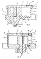
- FIG. 2 shows a sectional view of a first embodiment of the vane pump 2 according to the invention.
- the flange 8 and the peripheral part 10 are made in one piece in the present embodiment.
- the rotor unit 16 is driven.
- the rotor shaft 14 and a rotor base portion 18, in which the slide member 20 is slidably disposed are integrally formed in the present embodiment, the slide member 20 divides the pump chamber 6, as in FIG. 1 shown, in two sub-chambers 5, 7.
- the rotor shaft 14 may be connected in a known manner by a non-illustrated coupling with a camshaft of the internal combustion engine.
- the cover element 12 is made in the present embodiment of a flexible material, such as sheet metal, and is connected via a clip connection 22 with the peripheral part 10.
- the clip connection 22 in this case consists of recesses 24, 26 engage in the Klips institute 28, wherein the left side of the vane pump 2 is shown without engaging Klips institute 28.
- the recesses 24, 26 may also be designed as a continuous, circumferential recess, so that a circumferential clip element 28 produces the clip connection.
- FIG. 3 Now shows a further embodiment of the vane pump according to the invention 2.
- the vane pump 2 according to FIG. 3 is basically the same as the vane pump 2 made FIG. 2 , Recognizable in this embodiment is still an oil drain opening 26 with built-in valve.
- the cover part 12 is rigid and, for the purpose of saving weight, has essentially a smaller thickness than the cover part 12 FIG. 2 on. Here, however, ribs are still provided to ensure the necessary rigidity.
- the cover part 12 has a circumferential recess 30.
- the peripheral part 10 has a number of circumferentially distributed openings 32 through which two-legged spring members 34 engage the recess 30. In this case, a first, directed to the rotor unit 16 leg 36 is supported on the cover part 12. A second leg 38 facing away from the rotor unit 16 is supported in the recess on the peripheral part 10.
- the cover part 12 lifts off from a contact edge 40 of the peripheral part 10 and thus provides pressure relief by a fluidic connection of the two partial chambers 5, 7. It should be clear that Instead of a single circumferential recess 30, a plurality of recesses distributed over the circumference of the cover part 12 may be provided.
Landscapes
- Engineering & Computer Science (AREA)
- Mechanical Engineering (AREA)
- General Engineering & Computer Science (AREA)
- Physics & Mathematics (AREA)
- Fluid Mechanics (AREA)
- Rotary Pumps (AREA)
- Applications Or Details Of Rotary Compressors (AREA)
Description
Die Erfindung betrifft eine Flügelzellenpumpe für ein kompressibles Fluid mit einem abgedichteten Gehäuse, das eine Pumpenkammer aufweist, wobei das Gehäuse im Wesentlichen aus einem Flanschteil, einem Umfangsteil und einem Deckelteil aufgebaut ist, wobei in dem Flanschteil eine Rotorwelle mit einer Rotoreinheit, die mindestens ein Schieberelement aufweist, drehbar derart gelagert ist, dass die Rotoreinheit die Pumpenkammer in mindestens zwei Teilkammern unterteilt und ein Druck- / Unterdruckaufbau vorsieht.The invention relates to a vane pump for a compressible fluid having a sealed housing, which has a pump chamber, wherein the housing is essentially constructed of a flange, a peripheral part and a cover part, wherein in the flange part, a rotor shaft with a rotor unit, the at least one slide element has, is rotatably mounted such that the rotor unit divides the pump chamber into at least two sub-chambers and provides a pressure / negative pressure build-up.
Derartig Flügelzellenpumpen gelangen zum Beispiel in Bremssystemen von Kraftfahrzeugen zum Einsatz. Weitere Anwendungsgebiete sind Getriebe, Längssystem sowie aktive Fahrwerksysteme von Kraftfahrzeugen. Die
Die
Aufgabe der Erfindung ist es daher, eine kostengünstige, einfach aufgebaute Flügelzellenpumpe bereitzustellen, die den oben genannten Nachteil vermeidet.The object of the invention is therefore to provide a cost-effective, simply constructed vane pump, which avoids the above-mentioned disadvantage.
Diese Aufgabe wird dadurch gelöst, dass das Deckelteil in Axialrichtung der Rotorwelle beweglich ausgeführt ist, derart, dass bei einem zu hohen Druck in einer Teilkammer eine Druckentlastung durch eine fluidische Verbindung zur benachbarten Teilkammer erfolgt. Ein derartig bewegliches Deckelteil ermöglicht durch seine Flexibilität ein Überströmen des Fluids in eine benachbarte Kammer und damit einen kurzfristigen Druckabbau, wodurch ein Ausfall der Vakuumpumpe verhindert werden kann. Eine vorteilhafte Ausführungsform ergibt sich dadurch, dass das Deckelteil radial abgedichtet flexibel auf dem Umfangsteil angeordnet ist. Hierbei kann eine elastische Klips- oder Federverbindung das Deckelteil mit dem Umfangsteil verbinden. Auf diese Weise ist es möglich, eine Beweglichkeit in Axialrichtung auf einfache Weise mit einem einfachen Deckelteil herzustellen.This object is achieved in that the cover part is designed to be movable in the axial direction of the rotor shaft, such that when the pressure in a sub-chamber is too high, pressure is relieved by a fluidic connection to the adjacent sub-chamber. Such a movable cover part allows by its flexibility an overflow of the fluid into an adjacent chamber and thus a short-term pressure reduction, whereby a failure of the vacuum pump can be prevented. An advantageous embodiment results from the fact that the cover part is arranged radially sealed flexible on the peripheral part. In this case, an elastic Klips- or spring connection connect the cover part with the peripheral part. In this way it is possible to produce a mobility in the axial direction in a simple manner with a simple cover part.
Das Deckelteil kann jedoch auch flexibel ausgeführt sein, so dass es für sich oder in Verbindung mit einer elastischen Klips- oder Federverbindung die nötige Beweglichkeit in Axialrichtung bereitstellt. Hierbei kann das Deckelteil starr, beispielsweise mit Schrauben mit dem Umfangsteil verbunden sein, so dass keine Anpassung des Montageprozesses notwendig ist.However, the cover part can also be made flexible, so that it provides the necessary mobility in the axial direction, either alone or in conjunction with an elastic Klips- or spring connection. In this case, the cover part can be rigidly connected, for example with screws, to the peripheral part, so that no adaptation of the assembly process is necessary.
Besonders vorteilhaft ist eine Ausführungsform bei der das Deckelteil in Umfangsrichtung mindestens eine Aussparung und das Umfangsteil über den Umfang verteilte Öffnungen aufweisen, wobei zweischenkelige Federorgane vorgesehen sind, die durch die Öffnungen hindurchreichen und sich mit dem ersten, zur Rotereinheit gerichteten Schenkel am Deckelteil abstützen und sich mit dem zweiten, von der Rotereinheit abgewandten Schenkel am Umfangsteil abstützen. Hierbei kann das Deckelteil alternativ auch eine umlaufende Aussparung aufweisen.Particularly advantageous is an embodiment in which the cover part in the circumferential direction at least one recess and the peripheral part over have the circumference distributed openings, wherein two-legged spring members are provided, which extend through the openings and are supported with the first, directed to the rotor unit leg on the cover part and are supported with the second, remote from the rotor unit leg on the peripheral part. In this case, the cover part may alternatively also have a circumferential recess.
Des Weiteren kann es vorteilhaft sein, dass das Flanschteil um das Umfangsteil einstückig ausgeführt ist.Furthermore, it may be advantageous for the flange part to be made in one piece around the peripheral part.
Die Erfindung wird nachfolgend anhand der Zeichnung näher erläutert, hierbei zeigt:
-
Figur 1 eine schematische Perspektivansicht der geöffneten Flügelzellenpumpe, -
Figur 2 -
Figur 3 eine Schnittansicht einer zweiten Ausführungsform der erfindungsgemäßen Flügelzellenpumpe.
-
FIG. 1 a schematic perspective view of the open vane pump, -
FIG. 2 a sectional view of a first embodiment of the vane pump according to the invention, and -
FIG. 3 a sectional view of a second embodiment of the vane pump according to the invention.
Für den Fall, dass insbesondere in der Startphase, aufgrund von zähflüssigen Schmieröl ein zu hoher Druck auf das Schieberelement 20 wirkt, ist das Deckelelement 12 in Axialrichtung aufgrund des Werkstoffes und der Klipsverbindung beweglich, so dass die zwei Teilkammern 5, 7 fluidisch miteinander verbunden sind, und dementsprechend eine Druckentlastung stattfindet.In the event that too high a pressure acts on the
Bei einem in einer Teilkammer 5, 7 vorherrschenden zu hohen Druck hebt sich das Deckelteil 12 von einer Anlagekante 40 des Umfangteils 10 ab und sorgt auf diese Weise für eine Druckentlastung durch eine fluidische Verbindung der beiden Teilkammern 5, 7. Es sollte deutlich sein, dass anstatt einer einzigen umlaufenden Aussparung 30 auch mehrere, über dem Umfang des Deckelteils 12 verteilte Aussparungen vorgesehen sein können.In the case of a too high pressure prevailing in a
Claims (8)
- A vane pump for a compressible fluid having a sealed housing (4) comprising a pump chamber (6), wherein the housing (4) is constructed substantially from a flange part (8), a peripheral part (10) and a cover part (12), wherein a rotor shaft (14) with a rotor unit (16) comprising at least one vane element (20) is supported for rotation in the flange part (8) such that the rotor unit (16) divides the pump chamber (6) into at least two partial chambers (5, 7) and provides for pressure/vacuum buildup, characterized in that the cover part (12) is designed to be movable in the axial direction of the rotor shaft (14) such that in the event of excessive pressure in one partial chamber (5, 7) pressure relief is effected via fluid communication with the adjacent partial chamber (5, 7).
- The vane pump of claim 1, characterized in that the cover part (12) is arranged in a flexible manner on the peripheral part (10), the cover part being radially sealed.
- The vane pump of claim 2, characterized in that the cover part (12) is connected with the peripheral part (10) through an elastic clip or spring connection (22, 34).
- The vane pump of one of the preceding claims, characterized in that the cover part (12) is flexible.
- The vane pump of claim 4, characterized in that the cover part is rigidly connected with the peripheral part (10), for instance by means of screws.
- The vane pump of claim 3, characterized in that the cover part (12) has at least one recess (30) in the circumferential direction and the peripheral part (10) has openings (32) distributed over the periphery, wherein two-legged spring elements (34) are provided that pass through the openings (32) and bear on the cover part (12) with the first leg (36) directed towards the rotor unit (16) and bear on the peripheral part (10) with the second leg (38) averted from the rotor unit (16).
- The vane pump of claim 6, characterized in that the cover part has a continuous recess (30) extending in the circumferential direction.
- The vane pump of one of the preceding claims, characterized in that the flange part (8) and the peripheral part (10) are integral.
Priority Applications (2)
| Application Number | Priority Date | Filing Date | Title |
|---|---|---|---|
| EP11182852.1A EP2574792B1 (en) | 2011-09-27 | 2011-09-27 | Vane pump |
| PCT/EP2012/063004 WO2013045127A2 (en) | 2011-09-27 | 2012-07-04 | Vane pump |
Applications Claiming Priority (1)
| Application Number | Priority Date | Filing Date | Title |
|---|---|---|---|
| EP11182852.1A EP2574792B1 (en) | 2011-09-27 | 2011-09-27 | Vane pump |
Publications (2)
| Publication Number | Publication Date |
|---|---|
| EP2574792A1 EP2574792A1 (en) | 2013-04-03 |
| EP2574792B1 true EP2574792B1 (en) | 2015-06-03 |
Family
ID=46489210
Family Applications (1)
| Application Number | Title | Priority Date | Filing Date |
|---|---|---|---|
| EP11182852.1A Active EP2574792B1 (en) | 2011-09-27 | 2011-09-27 | Vane pump |
Country Status (2)
| Country | Link |
|---|---|
| EP (1) | EP2574792B1 (en) |
| WO (1) | WO2013045127A2 (en) |
Families Citing this family (1)
| Publication number | Priority date | Publication date | Assignee | Title |
|---|---|---|---|---|
| CN110291302B (en) | 2017-01-30 | 2021-08-17 | 利滕斯汽车合伙公司 | Clutch Vacuum Pump System |
Family Cites Families (4)
| Publication number | Priority date | Publication date | Assignee | Title |
|---|---|---|---|---|
| FR1450639A (en) * | 1965-06-30 | 1966-06-24 | Beaudouin Sa Ets | Improvements to mechanical oil injection and air injection vacuum pumps |
| DE3832042C2 (en) | 1987-10-05 | 1997-08-14 | Barmag Barmer Maschf | Vane pump |
| JPH09310773A (en) * | 1996-05-22 | 1997-12-02 | Daihatsu Motor Co Ltd | Breather device |
| JP5448394B2 (en) * | 2008-08-27 | 2014-03-19 | 三菱重工業株式会社 | Compressor safety valve |
-
2011
- 2011-09-27 EP EP11182852.1A patent/EP2574792B1/en active Active
-
2012
- 2012-07-04 WO PCT/EP2012/063004 patent/WO2013045127A2/en not_active Ceased
Also Published As
| Publication number | Publication date |
|---|---|
| WO2013045127A3 (en) | 2013-08-29 |
| WO2013045127A2 (en) | 2013-04-04 |
| EP2574792A1 (en) | 2013-04-03 |
Similar Documents
| Publication | Publication Date | Title |
|---|---|---|
| DE102016120502B4 (en) | GERO PUMP FOR A VEHICLE | |
| WO2016096755A1 (en) | Electric oil pump, in particular for a motor vehicle | |
| EP3263835A1 (en) | Vane pump with pressurisable under wing area | |
| EP2126391B1 (en) | Spring pressure multiplate clutch for compressors | |
| DE102019132729A1 (en) | Bead seal | |
| WO2020136269A1 (en) | Rotary pump with axial compensation, outlet seal for a pump, and pre-assembled pump unit | |
| EP2574792B1 (en) | Vane pump | |
| DE112010001701B4 (en) | Vane pump with improved rotor and rotary valve extension ring | |
| EP3903005A1 (en) | Rotary pump with axial compensation, outlet seal for a pump, and pre-assembled pump unit | |
| EP3903006A1 (en) | Rotary pump with axial compensation, outlet seal for a pump, and pre-assembled pump unit | |
| EP3475574B1 (en) | Dry-running vane gas pump | |
| DE102016200893A1 (en) | pumps Fields | |
| AT505061B1 (en) | ROTARY PUMP | |
| DE102014213626A1 (en) | Starting element, gearbox and drive train with the starting element | |
| DE102011078064A1 (en) | Internal gear pump | |
| EP1754906B1 (en) | Fastening of a central release device to a clutch | |
| DE102016204098A1 (en) | Vane pump | |
| DE102020133200A1 (en) | bead seal | |
| DE102013222591B4 (en) | Pump arrangement with vacuum pump and lubricant | |
| WO2017076418A1 (en) | Motor vehicle vacuum pump | |
| EP2479434A2 (en) | Regulation of an external gear pump | |
| DE102011055020A1 (en) | Pump module of pump such as cartridge pump, inserted into separate gear housing, has pressure plate having bearing recess which is sealed relative to pressure chamber by the pressure receiving element | |
| DE102018110025A1 (en) | displacement | |
| DE102014201877A1 (en) | Filter element for baffle openings of a switchable coolant pump | |
| DE102016011444A1 (en) | Arrangement for a screw compressor of a commercial vehicle |
Legal Events
| Date | Code | Title | Description |
|---|---|---|---|
| PUAI | Public reference made under article 153(3) epc to a published international application that has entered the european phase |
Free format text: ORIGINAL CODE: 0009012 |
|
| AK | Designated contracting states |
Kind code of ref document: A1 Designated state(s): AL AT BE BG CH CY CZ DE DK EE ES FI FR GB GR HR HU IE IS IT LI LT LU LV MC MK MT NL NO PL PT RO RS SE SI SK SM TR |
|
| AX | Request for extension of the european patent |
Extension state: BA ME |
|
| 17P | Request for examination filed |
Effective date: 20130924 |
|
| RBV | Designated contracting states (corrected) |
Designated state(s): AL AT BE BG CH CY CZ DE DK EE ES FI FR GB GR HR HU IE IS IT LI LT LU LV MC MK MT NL NO PL PT RO RS SE SI SK SM TR |
|
| GRAP | Despatch of communication of intention to grant a patent |
Free format text: ORIGINAL CODE: EPIDOSNIGR1 |
|
| INTG | Intention to grant announced |
Effective date: 20141107 |
|
| GRAS | Grant fee paid |
Free format text: ORIGINAL CODE: EPIDOSNIGR3 |
|
| GRAP | Despatch of communication of intention to grant a patent |
Free format text: ORIGINAL CODE: EPIDOSNIGR1 |
|
| GRAA | (expected) grant |
Free format text: ORIGINAL CODE: 0009210 |
|
| INTG | Intention to grant announced |
Effective date: 20150420 |
|
| AK | Designated contracting states |
Kind code of ref document: B1 Designated state(s): AL AT BE BG CH CY CZ DE DK EE ES FI FR GB GR HR HU IE IS IT LI LT LU LV MC MK MT NL NO PL PT RO RS SE SI SK SM TR |
|
| REG | Reference to a national code |
Ref country code: GB Ref legal event code: FG4D Free format text: NOT ENGLISH |
|
| REG | Reference to a national code |
Ref country code: CH Ref legal event code: EP |
|
| REG | Reference to a national code |
Ref country code: AT Ref legal event code: REF Ref document number: 730082 Country of ref document: AT Kind code of ref document: T Effective date: 20150715 Ref country code: IE Ref legal event code: FG4D Free format text: LANGUAGE OF EP DOCUMENT: GERMAN |
|
| REG | Reference to a national code |
Ref country code: DE Ref legal event code: R096 Ref document number: 502011006983 Country of ref document: DE |
|
| PG25 | Lapsed in a contracting state [announced via postgrant information from national office to epo] |
Ref country code: FI Free format text: LAPSE BECAUSE OF FAILURE TO SUBMIT A TRANSLATION OF THE DESCRIPTION OR TO PAY THE FEE WITHIN THE PRESCRIBED TIME-LIMIT Effective date: 20150603 Ref country code: HR Free format text: LAPSE BECAUSE OF FAILURE TO SUBMIT A TRANSLATION OF THE DESCRIPTION OR TO PAY THE FEE WITHIN THE PRESCRIBED TIME-LIMIT Effective date: 20150603 Ref country code: NO Free format text: LAPSE BECAUSE OF FAILURE TO SUBMIT A TRANSLATION OF THE DESCRIPTION OR TO PAY THE FEE WITHIN THE PRESCRIBED TIME-LIMIT Effective date: 20150903 Ref country code: LT Free format text: LAPSE BECAUSE OF FAILURE TO SUBMIT A TRANSLATION OF THE DESCRIPTION OR TO PAY THE FEE WITHIN THE PRESCRIBED TIME-LIMIT Effective date: 20150603 Ref country code: ES Free format text: LAPSE BECAUSE OF FAILURE TO SUBMIT A TRANSLATION OF THE DESCRIPTION OR TO PAY THE FEE WITHIN THE PRESCRIBED TIME-LIMIT Effective date: 20150603 |
|
| REG | Reference to a national code |
Ref country code: NL Ref legal event code: MP Effective date: 20150603 |
|
| REG | Reference to a national code |
Ref country code: LT Ref legal event code: MG4D |
|
| PG25 | Lapsed in a contracting state [announced via postgrant information from national office to epo] |
Ref country code: LV Free format text: LAPSE BECAUSE OF FAILURE TO SUBMIT A TRANSLATION OF THE DESCRIPTION OR TO PAY THE FEE WITHIN THE PRESCRIBED TIME-LIMIT Effective date: 20150603 Ref country code: BG Free format text: LAPSE BECAUSE OF FAILURE TO SUBMIT A TRANSLATION OF THE DESCRIPTION OR TO PAY THE FEE WITHIN THE PRESCRIBED TIME-LIMIT Effective date: 20150903 Ref country code: RS Free format text: LAPSE BECAUSE OF FAILURE TO SUBMIT A TRANSLATION OF THE DESCRIPTION OR TO PAY THE FEE WITHIN THE PRESCRIBED TIME-LIMIT Effective date: 20150603 Ref country code: GR Free format text: LAPSE BECAUSE OF FAILURE TO SUBMIT A TRANSLATION OF THE DESCRIPTION OR TO PAY THE FEE WITHIN THE PRESCRIBED TIME-LIMIT Effective date: 20150904 |
|
| PG25 | Lapsed in a contracting state [announced via postgrant information from national office to epo] |
Ref country code: EE Free format text: LAPSE BECAUSE OF FAILURE TO SUBMIT A TRANSLATION OF THE DESCRIPTION OR TO PAY THE FEE WITHIN THE PRESCRIBED TIME-LIMIT Effective date: 20150603 |
|
| PG25 | Lapsed in a contracting state [announced via postgrant information from national office to epo] |
Ref country code: SK Free format text: LAPSE BECAUSE OF FAILURE TO SUBMIT A TRANSLATION OF THE DESCRIPTION OR TO PAY THE FEE WITHIN THE PRESCRIBED TIME-LIMIT Effective date: 20150603 Ref country code: PL Free format text: LAPSE BECAUSE OF FAILURE TO SUBMIT A TRANSLATION OF THE DESCRIPTION OR TO PAY THE FEE WITHIN THE PRESCRIBED TIME-LIMIT Effective date: 20150603 Ref country code: PT Free format text: LAPSE BECAUSE OF FAILURE TO SUBMIT A TRANSLATION OF THE DESCRIPTION OR TO PAY THE FEE WITHIN THE PRESCRIBED TIME-LIMIT Effective date: 20151006 Ref country code: RO Free format text: LAPSE BECAUSE OF NON-PAYMENT OF DUE FEES Effective date: 20150603 Ref country code: CZ Free format text: LAPSE BECAUSE OF FAILURE TO SUBMIT A TRANSLATION OF THE DESCRIPTION OR TO PAY THE FEE WITHIN THE PRESCRIBED TIME-LIMIT Effective date: 20150603 Ref country code: IS Free format text: LAPSE BECAUSE OF FAILURE TO SUBMIT A TRANSLATION OF THE DESCRIPTION OR TO PAY THE FEE WITHIN THE PRESCRIBED TIME-LIMIT Effective date: 20151003 |
|
| REG | Reference to a national code |
Ref country code: DE Ref legal event code: R097 Ref document number: 502011006983 Country of ref document: DE |
|
| PLBE | No opposition filed within time limit |
Free format text: ORIGINAL CODE: 0009261 |
|
| STAA | Information on the status of an ep patent application or granted ep patent |
Free format text: STATUS: NO OPPOSITION FILED WITHIN TIME LIMIT |
|
| PG25 | Lapsed in a contracting state [announced via postgrant information from national office to epo] |
Ref country code: DK Free format text: LAPSE BECAUSE OF FAILURE TO SUBMIT A TRANSLATION OF THE DESCRIPTION OR TO PAY THE FEE WITHIN THE PRESCRIBED TIME-LIMIT Effective date: 20150603 Ref country code: LU Free format text: LAPSE BECAUSE OF FAILURE TO SUBMIT A TRANSLATION OF THE DESCRIPTION OR TO PAY THE FEE WITHIN THE PRESCRIBED TIME-LIMIT Effective date: 20150927 Ref country code: MC Free format text: LAPSE BECAUSE OF FAILURE TO SUBMIT A TRANSLATION OF THE DESCRIPTION OR TO PAY THE FEE WITHIN THE PRESCRIBED TIME-LIMIT Effective date: 20150603 |
|
| REG | Reference to a national code |
Ref country code: CH Ref legal event code: PL |
|
| 26N | No opposition filed |
Effective date: 20160304 |
|
| GBPC | Gb: european patent ceased through non-payment of renewal fee |
Effective date: 20150927 |
|
| PG25 | Lapsed in a contracting state [announced via postgrant information from national office to epo] |
Ref country code: SI Free format text: LAPSE BECAUSE OF FAILURE TO SUBMIT A TRANSLATION OF THE DESCRIPTION OR TO PAY THE FEE WITHIN THE PRESCRIBED TIME-LIMIT Effective date: 20150603 |
|
| REG | Reference to a national code |
Ref country code: IE Ref legal event code: MM4A |
|
| PG25 | Lapsed in a contracting state [announced via postgrant information from national office to epo] |
Ref country code: GB Free format text: LAPSE BECAUSE OF NON-PAYMENT OF DUE FEES Effective date: 20150927 Ref country code: CH Free format text: LAPSE BECAUSE OF NON-PAYMENT OF DUE FEES Effective date: 20150930 Ref country code: IE Free format text: LAPSE BECAUSE OF NON-PAYMENT OF DUE FEES Effective date: 20150927 Ref country code: LI Free format text: LAPSE BECAUSE OF NON-PAYMENT OF DUE FEES Effective date: 20150930 |
|
| REG | Reference to a national code |
Ref country code: FR Ref legal event code: PLFP Year of fee payment: 6 |
|
| PG25 | Lapsed in a contracting state [announced via postgrant information from national office to epo] |
Ref country code: MT Free format text: LAPSE BECAUSE OF FAILURE TO SUBMIT A TRANSLATION OF THE DESCRIPTION OR TO PAY THE FEE WITHIN THE PRESCRIBED TIME-LIMIT Effective date: 20150603 |
|
| PG25 | Lapsed in a contracting state [announced via postgrant information from national office to epo] |
Ref country code: HU Free format text: LAPSE BECAUSE OF FAILURE TO SUBMIT A TRANSLATION OF THE DESCRIPTION OR TO PAY THE FEE WITHIN THE PRESCRIBED TIME-LIMIT; INVALID AB INITIO Effective date: 20110927 Ref country code: SM Free format text: LAPSE BECAUSE OF FAILURE TO SUBMIT A TRANSLATION OF THE DESCRIPTION OR TO PAY THE FEE WITHIN THE PRESCRIBED TIME-LIMIT Effective date: 20150603 |
|
| PG25 | Lapsed in a contracting state [announced via postgrant information from national office to epo] |
Ref country code: CY Free format text: LAPSE BECAUSE OF FAILURE TO SUBMIT A TRANSLATION OF THE DESCRIPTION OR TO PAY THE FEE WITHIN THE PRESCRIBED TIME-LIMIT Effective date: 20150603 Ref country code: NL Free format text: LAPSE BECAUSE OF FAILURE TO SUBMIT A TRANSLATION OF THE DESCRIPTION OR TO PAY THE FEE WITHIN THE PRESCRIBED TIME-LIMIT Effective date: 20150603 Ref country code: SE Free format text: LAPSE BECAUSE OF FAILURE TO SUBMIT A TRANSLATION OF THE DESCRIPTION OR TO PAY THE FEE WITHIN THE PRESCRIBED TIME-LIMIT Effective date: 20150603 |
|
| PG25 | Lapsed in a contracting state [announced via postgrant information from national office to epo] |
Ref country code: BE Free format text: LAPSE BECAUSE OF NON-PAYMENT OF DUE FEES Effective date: 20150930 |
|
| PG25 | Lapsed in a contracting state [announced via postgrant information from national office to epo] |
Ref country code: TR Free format text: LAPSE BECAUSE OF FAILURE TO SUBMIT A TRANSLATION OF THE DESCRIPTION OR TO PAY THE FEE WITHIN THE PRESCRIBED TIME-LIMIT Effective date: 20150603 |
|
| REG | Reference to a national code |
Ref country code: FR Ref legal event code: PLFP Year of fee payment: 7 |
|
| REG | Reference to a national code |
Ref country code: AT Ref legal event code: MM01 Ref document number: 730082 Country of ref document: AT Kind code of ref document: T Effective date: 20160927 |
|
| PG25 | Lapsed in a contracting state [announced via postgrant information from national office to epo] |
Ref country code: AT Free format text: LAPSE BECAUSE OF NON-PAYMENT OF DUE FEES Effective date: 20160927 |
|
| PG25 | Lapsed in a contracting state [announced via postgrant information from national office to epo] |
Ref country code: MK Free format text: LAPSE BECAUSE OF FAILURE TO SUBMIT A TRANSLATION OF THE DESCRIPTION OR TO PAY THE FEE WITHIN THE PRESCRIBED TIME-LIMIT Effective date: 20150603 |
|
| REG | Reference to a national code |
Ref country code: FR Ref legal event code: PLFP Year of fee payment: 8 |
|
| PG25 | Lapsed in a contracting state [announced via postgrant information from national office to epo] |
Ref country code: AL Free format text: LAPSE BECAUSE OF FAILURE TO SUBMIT A TRANSLATION OF THE DESCRIPTION OR TO PAY THE FEE WITHIN THE PRESCRIBED TIME-LIMIT Effective date: 20150603 |
|
| REG | Reference to a national code |
Ref country code: DE Ref legal event code: R082 Ref document number: 502011006983 Country of ref document: DE Representative=s name: TERPATENT PARTGMBB, DE Ref country code: DE Ref legal event code: R082 Ref document number: 502011006983 Country of ref document: DE Representative=s name: TERPATENT PATENTANWAELTE TER SMITTEN EBERLEIN-, DE |
|
| PGFP | Annual fee paid to national office [announced via postgrant information from national office to epo] |
Ref country code: DE Payment date: 20240919 Year of fee payment: 14 |
|
| PGFP | Annual fee paid to national office [announced via postgrant information from national office to epo] |
Ref country code: FR Payment date: 20240924 Year of fee payment: 14 |
|
| PGFP | Annual fee paid to national office [announced via postgrant information from national office to epo] |
Ref country code: IT Payment date: 20240930 Year of fee payment: 14 |