EP3573328A1 - Method and apparatus for protecting device under strong light - Google Patents
Method and apparatus for protecting device under strong light Download PDFInfo
- Publication number
- EP3573328A1 EP3573328A1 EP18742186.2A EP18742186A EP3573328A1 EP 3573328 A1 EP3573328 A1 EP 3573328A1 EP 18742186 A EP18742186 A EP 18742186A EP 3573328 A1 EP3573328 A1 EP 3573328A1
- Authority
- EP
- European Patent Office
- Prior art keywords
- camera device
- instruction
- sending
- image
- shutter
- Prior art date
- Legal status (The legal status is an assumption and is not a legal conclusion. Google has not performed a legal analysis and makes no representation as to the accuracy of the status listed.)
- Granted
Links
Images



Classifications
-
- H—ELECTRICITY
- H04—ELECTRIC COMMUNICATION TECHNIQUE
- H04N—PICTORIAL COMMUNICATION, e.g. TELEVISION
- H04N23/00—Cameras or camera modules comprising electronic image sensors; Control thereof
- H04N23/60—Control of cameras or camera modules
- H04N23/66—Remote control of cameras or camera parts, e.g. by remote control devices
-
- H—ELECTRICITY
- H04—ELECTRIC COMMUNICATION TECHNIQUE
- H04N—PICTORIAL COMMUNICATION, e.g. TELEVISION
- H04N23/00—Cameras or camera modules comprising electronic image sensors; Control thereof
- H04N23/60—Control of cameras or camera modules
- H04N23/695—Control of camera direction for changing a field of view, e.g. pan, tilt or based on tracking of objects
-
- H—ELECTRICITY
- H04—ELECTRIC COMMUNICATION TECHNIQUE
- H04N—PICTORIAL COMMUNICATION, e.g. TELEVISION
- H04N23/00—Cameras or camera modules comprising electronic image sensors; Control thereof
- H04N23/60—Control of cameras or camera modules
-
- H—ELECTRICITY
- H04—ELECTRIC COMMUNICATION TECHNIQUE
- H04N—PICTORIAL COMMUNICATION, e.g. TELEVISION
- H04N23/00—Cameras or camera modules comprising electronic image sensors; Control thereof
- H04N23/70—Circuitry for compensating brightness variation in the scene
- H04N23/73—Circuitry for compensating brightness variation in the scene by influencing the exposure time
-
- H—ELECTRICITY
- H04—ELECTRIC COMMUNICATION TECHNIQUE
- H04N—PICTORIAL COMMUNICATION, e.g. TELEVISION
- H04N23/00—Cameras or camera modules comprising electronic image sensors; Control thereof
- H04N23/70—Circuitry for compensating brightness variation in the scene
- H04N23/75—Circuitry for compensating brightness variation in the scene by influencing optical camera components
-
- H—ELECTRICITY
- H10—SEMICONDUCTOR DEVICES; ELECTRIC SOLID-STATE DEVICES NOT OTHERWISE PROVIDED FOR
- H10F—INORGANIC SEMICONDUCTOR DEVICES SENSITIVE TO INFRARED RADIATION, LIGHT, ELECTROMAGNETIC RADIATION OF SHORTER WAVELENGTH OR CORPUSCULAR RADIATION
- H10F39/00—Integrated devices, or assemblies of multiple devices, comprising at least one element covered by group H10F30/00, e.g. radiation detectors comprising photodiode arrays
- H10F39/80—Constructional details of image sensors
- H10F39/802—Geometry or disposition of elements in pixels, e.g. address-lines or gate electrodes
Definitions
- the application relates to the technical field of image capture devices, and in particular, to a method and apparatus for protecting a device under powerful light.
- a photosensitive element in a camera device is a precision component. If the photosensitive element is aligned with a powerful light source, the photosensitive element is easily damaged by powerful light.
- Embodiments of the disclosure provide a method and apparatus for protecting a device under powerful light, so as to reduce the damage caused by the powerful light to a photosensitive element in the camera device.
- An embodiment of the disclosure discloses a method for protecting a device under powerful light, including:
- the light avoidance instruction is an instruction for rotating the camera device or an instruction for closing a shutter of the camera device
- sending a light avoidance instruction includes: sending the instruction for rotating the camera device so as to cause the camera device to rotate in a direction away from the light source based on the instruction for rotating the camera device; or, sending the instruction for closing a shutter of the camera device so as to cause the shutter to shield a photosensitive element of the camera device.
- the light avoidance instruction is an instruction for rotating the camera device or an instruction for closing a shutter of the camera device, and sending a light avoidance instruction, includes:
- sending the instruction for rotating the camera device includes:
- the method further includes: activating a timer, and after a third preset duration, sending a return instruction; wherein the return instruction carries information of a return path, so as to cause the camera device to return to an initial position based on the information of the return path, and the initial position is: a position where the camera device is located before rotating based on the information of the rotation path.
- the method further includes:
- the method further includes:
- the method further includes:
- determining whether the camera device is rotatable may include:
- sending an instruction for rotating the camera device may include:
- An embodiment of the disclosure further discloses an apparatus for protecting a device under powerful light, including:
- the light avoidance instruction is an instruction for rotating the camera device or an instruction for closing a shutter of the camera device.
- the first sending module includes a first sending sub-module.
- the light avoidance instruction is the instruction for closing a shutter of the camera device, the first sending module includes a second sending sub-module.
- the first sending sub-module is configured to send the instruction for rotating the camera device so as to cause the camera device to rotate in the direction away from the light source based on the instruction for rotating the camera device.
- the second sending sub-module is configured to send the instruction for closing a shutter of the camera device so as to cause the shutter to shield the photosensitive element of the camera device.
- the light avoidance instruction is an instruction for rotating the camera device or an instruction for closing a shutter of the camera device;
- the first sending module includes a judgment sub-module, a third sending sub-module and a fourth sending sub-module; wherein, the judgment sub-module is configured to determine whether the camera device is rotatable, and trigger the third sending sub-module if the camera device is rotatable, or trigger the fourth sending sub-module if the camera device is not rotatable;
- the third sending sub-module is configured to send the instruction for rotating the camera device so as to cause the camera device to rotate in the direction away from the light source based on the instruction for rotating the camera device; and the fourth sending sub-module is configured to send the instruction for closing the shutter of the camera device so as to cause the shutter to shield the photosensitive element of the camera device.
- the first sending sub-module or the third sending sub-module includes:
- the apparatus further includes: a third sending module, configured to activate a timer after the third sending sub-module sends the instruction for rotating the camera device, and send a return instruction after the third preset duration; wherein the return instruction carries information of a return path, so as to cause the camera device to return to an initial position based on the information of the return path, and the initial position is: a position where the camera device is located before rotating based on the information of the rotation path.
- a third sending module configured to activate a timer after the third sending sub-module sends the instruction for rotating the camera device, and send a return instruction after the third preset duration
- the return instruction carries information of a return path, so as to cause the camera device to return to an initial position based on the information of the return path, and the initial position is: a position where the camera device is located before rotating based on the information of the rotation path.
- the apparatus further includes:
- the apparatus further includes:
- the apparatus further includes:
- An embodiment of the disclosure further discloses a camera device including a processor, a communication interface, a memory and a communication bus; wherein, the processor, the communication interface, and the memory are communicated with each other via the communication bus; the memory is configured to store a computer program; and the processor is configured to implement any one of the above-described methods for protecting a device under powerful light when executing the program stored in the memory.
- An embodiment of the disclosure further discloses a computer readable storage medium.
- the computer readable storage medium stores a computer program therein.
- the computer program when executed by a processor, implements any one of the above-described methods for protecting a device under powerful light.
- An embodiment of the disclosure further discloses a computer program.
- the computer program when executed by a processor, implements any one of the above-described methods for protecting a device under powerful light.
- the photosensitive element in the camera device it is determined whether there is a powerful light source in an image captured by the camera device based on the number of the target pixels (pixels whose gray values are larger than the first preset threshold) in the image. If so, it is indicated that the photosensitive element in the camera device is aligned with the powerful light source. In this case, the light avoidance instruction is sent, so as to cause the photosensitive element of the camera device to avoid the light source, thereby reducing the damage caused by the powerful light to the photosensitive element in the camera device.
- the embodiments of the disclosure provide a method and apparatus for protecting a device under powerful light.
- the method and apparatus is applicable to a camera device, and is also applicable to an individual electronic device.
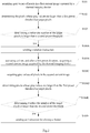
- Fig.1 is a first schematic flowchart of a method for protecting a device under powerful light according to an embodiment of the disclosure, the method includes S101-S104.
- S101 Acquiring a gray value of each of pixels in a first image captured by a camera device.
- the device implementing the present solution can be a camera device, and the camera device can analyze its captured image to acquire a gray value of each of pixels in the image.
- the device implementing the present solution can also be an independent electronic device.
- the electronic device is communicatively connected to the camera device, acquires and analyzes an image captured by the camera device, and acquires a gray value of each of pixels in the image.
- S102 Determining pixels, in the first image, whose gray values are larger than a first preset threshold as target pixels.
- the first preset threshold can be set based on actual conditions. For example, if a photosensitive element in the camera device is very sensitive, and thus may be damaged by slightly powerful light, the first preset threshold can be set to be a smaller value. If the photosensitive element in the camera device is not very sensitive, and thus can be damaged by only powerful light, the first preset threshold can be set to be a larger value.
- S103 Determining whether the number of the target pixels is larger than a second preset threshold, and if so, performing S103.
- the second preset threshold can be set based on actual conditions. For example, if a photosensitive element in the camera device is very sensitive, and thus may be damaged by slightly powerful light, the second preset threshold can be set to be a smaller value. If the photosensitive element in the camera device is not very sensitive, and thus can be damaged by only powerful light, the second preset threshold can be set to be a larger value.
- S104 Sending a light avoidance instruction so as to cause a photosensitive element of the camera device to avoid a light source.
- the light avoidance instruction can be an instruction for rotating the camera device or an instruction for closing the shutter of the camera device.
- S104 may include: sending the instruction for rotating the camera device so as to cause the camera device to rotate in a direction away from the light source; or, sending the instruction for closing the shutter of the camera device so as to cause the shutter to shield the photosensitive element of the camera device.
- S104 may include: determining whether the camera device is rotatable; if the camera device is rotatable, sending the instruction for rotating the camera device so as to cause the camera device to rotate in the direction away from the light source; if the camera device is not rotatable, sending the instruction for closing the shutter of the camera device so as to close the shutter to shield the photosensitive element of the camera device.
- the device implementing the present solution may determine, in the first image, an image region whose gray value is larger than a third preset threshold as a position of the light source in the first image, determine a rotation path of the camera device away from the light source based on the position of the light source in the first image, and send the instruction for rotating the camera device, which carries information of the rotation path, so as to cause the camera device to rotate in the direction away from the light source based on the information of the rotation path.
- the gray values of the pixels at the position of the light source in the first image are relatively large. Therefore, a region whose gray value is relatively large can be identified in the first image as the position of the light source. For example, a region in which a gray value of each pixel is larger than the third preset threshold can be identified as the position of the light source in the first image. A region in which an average gray value of pixels is larger than the third preset threshold can be identified as the position of the light source in the first image.
- the specific identification method is not limited thereto.
- the rotation path of the camera device is determined.
- the rotation path can include a rotation angle and a rotation direction.
- the rotation angle can be a fixed value, such as 180 degrees, 90 degrees, etc., which is not specifically limited.
- the rotation angle can also be a dynamic value.
- the rotation angle can be determined based on the position of the light source in the first image.
- the rotation direction can be preset.
- the camera device can rotate clockwise in a horizontal direction, counterclockwise in a horizontal direction, or up and down.
- the specific rotation direction is not limited thereto.
- the rotation direction can be determined based on the position of the light source in the first image.
- the coordinates of the circumscribed rectangle of the light source in the first image can be determined, and then, based on the coordinates of the circumscribed rectangle, the shortest path to remove the light source from the field of view is calculated; wherein, the shortest path includes the rotation angle and the rotation direction. In this way, the rotation path is determined.
- the camera device is horizontally rotated, and the camera device can be clockwise or counterclockwise rotated. It is assumed that the correspondence between the size of the circumscribed rectangle and the rotation angle is pre-stored, and the larger the circumscribed rectangle is, the larger the rotation angle is.
- the first image is 160 mm long and 120 mm high, and the determined circumscribed rectangle of the light source in the first image are located in the upper left corner. It is assumed that a point at the most upper left corner is taken as the origin in the image coordinate system of the first image and the coordinates of the four points of the circumscribed rectangle are (0,0), (0,1), (1,0) and (1,1) respectively.
- the light source is in the upper left corner in the first image, and is rotated to the right (i.e., in a direction away from the light source), that is, clockwise rotated.
- the rotation angle is determined to be 10 degrees based on the size of the circumscribed rectangle
- the information of the rotation path carried in the sent instruction for rotating the camera device includes: the camera device is clockwise rotated by 10 degrees.
- the device implementing the present solution sends the instruction for closing the shutter of the camera device to the camera device. After receiving the instruction for closing the shutter of the camera device, the camera device closes its shutter. In this way, the shutter can shield the light source so as to provide the shielding protection of the photosensitive element.
- a powerful light source exists in an image captured by the camera device based on the number of the target pixels (the pixels whose gray values are larger than the first preset threshold) in the image. If so, it is indicated that the photosensitive element in the camera device is aligned with the powerful light source. In this case, the light avoidance instruction is sent, so as to cause the photosensitive element of the camera device to avoid the light source, thereby reducing the damage caused by the powerful light to the photosensitive element in the camera device.
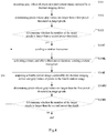
- Fig.2 is a second schematic flowchart of a method for protecting a device under powerful light according to an embodiment of the disclosure.
- the embodiment shown in Fig.2 is based on the embodiment shown in Fig.1 .
- S104 may include:
- the instruction for rotating the camera device is firstly sent, and after the preset duration (for example, 3 seconds) after sending the instruction for rotating the camera device, an image captured by the camera device is again acquired.
- the image acquired in S101 is referred to as the first image
- the image acquired in S104B is referred to as the second image. It can be understood that the moment for acquiring the first image is earlier than the moment for acquiring the second image.
- the processing of the second image is similar to that of the first image. It is determined whether the number of the target pixels in the second image is larger than the second preset threshold. If so, it is indicated that the camera device is still under the powerful light, that is to say, it is not possible to reduce the powerful light radiation of the camera device by rotating the camera device.
- the instruction for closing the shutter of the camera device is sent to the camera device.
- the camera device closes its shutter. In this way, the shutter can shield the light source so as to provide the shielding protection of the photosensitive element.
- the method may further include:
- the instruction for opening the shutter is sent to the camera device.
- the image captured by the camera device is acquired again.
- the image acquired at this time is referred to as the third image. It can be understood that the moment for acquiring the third image is later than the moment for acquiring the second image and the moment for acquiring the first image.
- the processing of the third image is similar to that of the second image. It is determined whether the number of the target pixels in the third image is larger than the second preset threshold. If so, it is indicated that the camera device is still under the powerful light, and at this time, the instruction for closing the shutter is sent to the camera device to close the shutter again. If not, it is indicated that the powerful light source is already not within the field of view, and at this time, the shutter is no longer closed.
- Fig.3 is a third schematic flowchart of a method for protecting a device under powerful light according to an embodiment of the disclosure.
- the embodiment shown in Fig.3 is based on the embodiment shown in Fig.1 .
- S104 may include: S104G: determining whether the camera device is rotatable; if the camera device is rotatable, performing S104H; if the camera device is not rotatable, performing S104I.
- a rotation component or rotation module, etc.
- the hardware configuration information of the thermal imaging device can also be read, and whether the thermal imaging device is rotatable is determined based on the hardware configuration information, and so on.
- the specific determination method is not limited thereto.
- S104H Determining a position of the light source based on the first image; determining a rotation path of the camera device away from the position; and sending the instruction for rotating the camera device, which carries information of the rotation path, so as to cause the camera device to rotate in the direction away from the position based on the information of the rotation path.
- S104I Sending an instruction for closing the shutter of the camera device so as to the shutter to shield the photosensitive element of the camera device.
- the device implementing the present solution can determine the position of the light source based on the first image, then determine the rotation path of the camera device away from the position, and send the instruction for rotating the camera device, which carries information of the rotation path. After receiving the instruction for rotating the camera device, the camera device rotates in the direction away from the position based on the information of the rotation path.
- the coordinates of the circumscribed rectangle of the light source in the first image can be determined; and then, based on the coordinates of the circumscribed rectangle, the shortest path to remove the light source from the field of view is calculated. In this way, the rotation path is determined.
- the device implementing the present solution can send the instruction for closing the shutter of the camera device to the camera device. After receiving the instruction for closing the shutter of the camera device, the camera device closes its shutter. In this way, the shutter can shield the light source so as to provide the shielding protection of the photosensitive element.
- the method may further include:
- the instruction for opening the shutter is sent to the camera device.
- the image captured by the camera device is acquired again.
- the image acquired at this time is referred to as the third image. It can be understood that the moment for acquiring the third image is later than the moment for acquiring the second image and the moment for acquiring the first image.
- the processing of the third image is similar to that of the second image. It is determined whether the number of the target pixels in the third image is larger than the second preset threshold. If so, it is indicated that the camera device is still under the powerful light, and at this time, the instruction for closing the shutter of the camera device is sent to close the shutter again. If not, it is indicated that the powerful light source is already not within the field of view, and at this time, the shutter is no longer closed.
- Fig.4 is a fourth schematic flowchart of a method for protecting a device under powerful light according to an embodiment of the disclosure.
- the embodiment shown in Fig.4 is based on the embodiment shown in Fig.1 .
- S104 may include:
- the return instruction carries information of a return path, so that the camera device returns to an initial position based on the information of the return path.
- the initial position is: a position where the camera device is located before it rotates based on the information of the rotation path.
- S104L Acquiring a fourth image captured by the camera device and gray values of pixels in the fourth image.
- S104M Determining pixels whose gray values are larger than the first preset threshold as the target pixels.
- S104N Determining whether the number of the target pixels is larger than the second preset threshold. If the number of the target pixels is larger than the second preset threshold, returning to S104J; and if the number of the target pixels is not larger than the second preset threshold, it is indicated that there is no powerful light source in the field of view of the camera device, and the process ends.
- the instruction for rotating the camera device is firstly sent, and after the preset duration (for example 1 minute) after sending the instruction for rotating the camera device, the return instruction is then sent, so that the camera device returns to the initial position, that is, the position where the camera device is located before rotating based on the above-described information of the rotation path.
- the preset duration for example 1 minute
- the camera device After returning to the initial position, the camera device acquires the image captured by the camera device again.
- the image acquired in S104L is referred to as the fourth image. It can be understood that the moment for acquiring the first image is earlier than the moment for acquiring the fourth image.
- the processing of the fourth image is similar to that of the first image. It is determined whether the number of the target pixels in the fourth image is larger than the second preset threshold. If so, it is indicated that the camera device is still under the powerful light. In this case, it is indicated that the powerful light source is still present, and the instruction for rotating the camera device is sent to the camera device again to make it away from the powerful light source.
- S104K-S104N in Fig.4 can also be added on the basis of the embodiment shown in Fig.3 and S104K-S104N are performed after S104H. If the determination result in S104N is YES, the process returns to S104H. If the determination result in S104N is NO, the process ends. The specific process is similar and thus to not be repeated.
- an embodiment of the disclosure also provides an apparatus for protecting a device under powerful light.
- Fig.5 is a schematic structural diagram of an apparatus for protecting a device under powerful light according to an embodiment of the disclosure, the apparatus includes:
- the light avoidance instruction is an instruction for rotating the camera device or an instruction for closing a shutter of the camera device.
- the first sending module includes a first sending sub-module.
- the light avoidance instruction is an instruction for closing a shutter of the camera device, the first sending module includes a second sending sub-module.
- the first sending sub-module configured to send the instruction for rotating the camera device so as to cause the camera device to rotate in a direction away from the light source based on the instruction for rotating the camera device.
- the second sending sub-module configured to send the instruction for closing a shutter of the camera device so as to the shutter to shield the photosensitive element of the camera device.
- the light avoidance instruction is an instruction for rotating the camera device or an instruction for closing a shutter of the camera device.
- the first sending module 504 includes a judgment sub-module, a third sending sub-module and a fourth sending sub-module (not shown in the figure), wherein, the judgment sub-module is configured to determine whether the camera device is rotatable, and trigger the third sending sub-module if the camera device is rotatable, or trigger the fourth sending sub-module if the camera device is not rotatable; the third sending sub-module is configured to send the instruction for rotating the camera device, so as to cause the camera device to rotate in the direction away from the light source based on the instruction for rotating the camera device; the fourth sending sub-module is configured to send the instruction for closing a shutter of the camera device so as to the shutter to shield the photosensitive element of the camera device.
- the first sending sub-module or the third sending sub-module may include: a first determining unit, a second determining unit and a sending unit (not shown in the figure), wherein, the first determining unit is configured to determine a position of the light source based on the first image; the second determining unit is configured to determine a rotation path of the camera device away from the position; and the sending unit is configured to send the instruction for rotating the camera device which carries information of the rotation path, so as to cause the camera device to rotate in the direction away from the position based on the information of the rotation path.
- the apparatus may further include: a third sending module (not shown in the figure), configured to activate a timer when the third sending sub-module sends the instruction for rotating the camera device, and after the third preset duration, send a return instruction; wherein the return instruction carries information of a return path, so as to cause the camera device to return to an initial position based on the information of the return path, and the initial position is: a position where the camera device is located before rotating based on the information of the rotation path;
- a third sending module (not shown in the figure), configured to activate a timer when the third sending sub-module sends the instruction for rotating the camera device, and after the third preset duration, send a return instruction
- the return instruction carries information of a return path, so as to cause the camera device to return to an initial position based on the information of the return path, and the initial position is: a position where the camera device is located before rotating based on the information of the rotation path;
- the apparatus may further include: a fifth acquisition module, a fourth determining module and a fourth judgment module (not shown in the figure), wherein, the fifth acquisition module is configured to acquire a fourth image captured by the camera device and gray values of pixels in the fourth image; the fourth determining module is configured to determine pixels whose gray values are larger than a first preset threshold as target pixels; and the fourth judgment module is configured to determine whether the number of the target pixels is larger than the second preset threshold, and trigger the sending module if the number of the target pixels is larger than the second preset threshold.
- the fifth acquisition module is configured to acquire a fourth image captured by the camera device and gray values of pixels in the fourth image
- the fourth determining module is configured to determine pixels whose gray values are larger than a first preset threshold as target pixels
- the fourth judgment module is configured to determine whether the number of the target pixels is larger than the second preset threshold, and trigger the sending module if the number of the target pixels is larger than the second preset threshold.
- the apparatus may further include: a first timing module, a second acquisition module, a third acquisition module, a second determining module and a second judgment module (not shown in the figure), wherein, the first timing module is configured to activate a timer after the first sending sub-module sends the instruction for rotating the camera device, and after the first preset duration, trigger the second acquisition module; the second acquisition module is configured to acquire a second image captured by the camera device; the third acquisition module is configured to acquire gray values of pixels in the second image; the second determining module is configured to determine pixels whose gray values are larger than a first preset threshold as target pixels; and the second judgment module is configured to determine whether the number of the target pixels is larger than the second preset threshold, and trigger the second sending sub-module if the number of the target pixels is larger than the second preset threshold.
- the first timing module is configured to activate a timer after the first sending sub-module sends the instruction for rotating the camera device, and after the first preset duration, trigger the second acquisition module
- the second acquisition module
- the apparatus may further include: a second timing module, a second sending module, a fourth acquisition module, a third determining module and a third judgment module (not shown in the figure), wherein, the second timing module is configured to activate a timer after the second sending sub-module or the fourth sending sub-module sends the instruction for closing the shutter of the camera device, and after the second preset duration, trigger the second sending module; the second sending module is configured to send an instruction for opening the shutter and acquire a third image captured by the camera device; the fourth acquisition module is configured to acquire gray values of pixels in the third image; the third determining module is configured to determine pixels whose gray values are larger than a first preset threshold as target pixels; and the third judgment module is configured to determine whether the number of the target pixels is larger than the second preset threshold, and trigger the second sending sub-module if the number of the target pixels is larger than the second preset threshold.
- the second timing module is configured to activate a timer after the second sending sub-module or the fourth sending sub-module sends
- the photosensitive element in the camera device it is determined whether there is a powerful light source in an image captured by the camera device based on the number of the target pixels (pixels whose gray values are larger than the first preset threshold) in the image. If so, it is indicated that the photosensitive element in the camera device is aligned with the powerful light source. In this case, the light avoidance instruction is sent, so as to cause the photosensitive element of the camera device to avoid the light source, thereby reducing the damage caused by the powerful light to the photosensitive element of the camera device.
- the camera device includes a processor 601, a communication interface 602, a memory 603 and a communication bus 604, wherein, the processor 601, the communication interface 602, and the memory 603 are communicated with each other via the communication bus 604; the memory 603 is configured to store a computer program; and the processor 601 is configured to implement any one of the above-described methods for protecting a device under powerful light when executing the program stored in the memory 603.
- the camera device further includes a photosensitive element, a shutter, and the like (not shown in the figure). Other components of the camera device are not described in the embodiments of the disclosure any longer.
- An embodiment of the disclosure further provides a computer readable storage medium.
- the computer readable storage medium stores a computer program therein.
- the computer program when executed by a processor, implements any one of the above-described methods for protecting a device under powerful light.
- An embodiment of the disclosure further provides a computer program.
- the computer program when executed by a processor, implements any one of the above-described methods for protecting a device under powerful light.
Landscapes
- Engineering & Computer Science (AREA)
- Multimedia (AREA)
- Signal Processing (AREA)
- Studio Devices (AREA)
Abstract
Description
- The application claims the priority to a Chinese Patent Application No.
201710031314.1 - The application relates to the technical field of image capture devices, and in particular, to a method and apparatus for protecting a device under powerful light.
- Powerful light is often present in working environment of a camera device. A photosensitive element in a camera device is a precision component. If the photosensitive element is aligned with a powerful light source, the photosensitive element is easily damaged by powerful light.
- Embodiments of the disclosure provide a method and apparatus for protecting a device under powerful light, so as to reduce the damage caused by the powerful light to a photosensitive element in the camera device.
- An embodiment of the disclosure discloses a method for protecting a device under powerful light, including:
- acquiring gray values of pixels in a first image captured by the camera device;
- determining pixels whose gray values are larger than a first preset threshold as target pixels;
- determining whether the number of the target pixels is larger than a second preset threshold; and
- if the number of the target pixels is larger than the second preset threshold, sending a light avoidance instruction so as to cause a photosensitive element of the camera device to avoid a light source.
- In one embodiment, the light avoidance instruction is an instruction for rotating the camera device or an instruction for closing a shutter of the camera device, and sending a light avoidance instruction, includes:
sending the instruction for rotating the camera device so as to cause the camera device to rotate in a direction away from the light source based on the instruction for rotating the camera device; or, sending the instruction for closing a shutter of the camera device so as to cause the shutter to shield a photosensitive element of the camera device. - In one embodiment, the light avoidance instruction is an instruction for rotating the camera device or an instruction for closing a shutter of the camera device, and sending a light avoidance instruction, includes:
- determining whether the camera device is rotatable;
- if the camera device is rotatable, sending the instruction for rotating the camera device so as to cause the camera device to rotate in a direction away from the light source based on the instruction for rotating the camera device;
- if the camera device is not rotatable, sending the instruction for closing a shutter of the camera device so as to cause the shutter to shield the photosensitive element of the camera device.
- In one embodiment, sending the instruction for rotating the camera device includes:
- determining a position of the light source based on the first image;
- determining a rotation path of the camera device away from the position;
- sending the instruction for rotating the camera device which carries information of the rotation path, so as to cause the camera device to rotate in the direction away from the position based on the information of the rotation path.
- In one embodiment, after sending the instruction for rotating the camera device, the method further includes:
activating a timer, and after a third preset duration, sending a return instruction; wherein the return instruction carries information of a return path, so as to cause the camera device to return to an initial position based on the information of the return path, and the initial position is: a position where the camera device is located before rotating based on the information of the rotation path. - In one embodiment, after sending a return instruction, the method further includes:
- acquiring a fourth image captured by the camera device and gray values of pixels in the fourth image;
- determining pixels whose gray values are larger than the first preset threshold as target pixels;
- determining whether the number of the target pixels is larger than the second preset threshold; and
- if the number of the target pixels is larger than the second preset threshold, returning to the step of sending the instruction for rotating the camera device.
- In one embodiment, after sending the instruction for rotating the camera device, the method further includes:
- activating a timer, and after a first preset duration, acquiring a second image captured by the camera device;
- acquiring gray values of pixels in the second image;
- determining pixels whose gray values are larger than the first preset threshold as target pixels;
- determining whether the number of the target pixels is larger than the second preset threshold; and
- if the number of the target pixels is larger than the second preset threshold, sending the instruction for closing a shutter of the camera device so as to cause the shutter to shield the photosensitive element of the camera device.
- In one embodiment, after sending the instruction for closing a shutter of the camera device, the method further includes:
- activating a timer, and after a second preset duration, sending an instruction for opening the shutter and acquiring a third image captured by the camera device;
- acquiring gray values of pixels in the third image;
- determining pixels whose gray values are larger than the first preset threshold as target pixels;
- determining whether the number of the target pixels is larger than the second preset threshold; and
- if the number of the target pixels is larger than the second preset threshold, sending the instruction for closing the shutter of the camera device.
- In one embodiment, determining whether the camera device is rotatable may include:
- determining whether a rotation component is provided in the camera device;
- or, reading hardware configuration information of the camera device, and determining whether the camera device is rotatable based on the hardware configuration information.
- In one embodiment, sending an instruction for rotating the camera device may include:
- determining, in the first image, an image region whose gray value is larger than a third preset threshold as a position of the light source in the first image;
- determining a rotation path of the camera device away from the light source based on the position of the light source in the first image; and
- sending the instruction for rotating the camera device which carries, information of the rotation path so as to cause the camera device to rotate in the direction away from the light source based on the information of the rotation path.
- An embodiment of the disclosure further discloses an apparatus for protecting a device under powerful light, including:
- a first acquisition module, configured to acquire gray values of pixels in a first image captured by the camera device;
- a first determining module, configured to determine pixels whose gray values are larger than a first preset threshold as target pixels;
- a first judgment module, configured to determine whether the number of the target pixels is larger than a second preset threshold, and trigger a first sending module if the number of the target pixels is larger than the second preset threshold; and
- the first sending module, configured to send a light avoidance instruction so as to cause a photosensitive element of the camera device to avoid a light source.
- In one embodiment, the light avoidance instruction is an instruction for rotating the camera device or an instruction for closing a shutter of the camera device. When the light avoidance instruction is the instruction for rotating the camera device, the first sending module includes a first sending sub-module. When the light avoidance instruction is the instruction for closing a shutter of the camera device, the first sending module includes a second sending sub-module.
- The first sending sub-module is configured to send the instruction for rotating the camera device so as to cause the camera device to rotate in the direction away from the light source based on the instruction for rotating the camera device.
- The second sending sub-module is configured to send the instruction for closing a shutter of the camera device so as to cause the shutter to shield the photosensitive element of the camera device.
- In one embodiment, the light avoidance instruction is an instruction for rotating the camera device or an instruction for closing a shutter of the camera device; the first sending module includes a judgment sub-module, a third sending sub-module and a fourth sending sub-module; wherein,
the judgment sub-module is configured to determine whether the camera device is rotatable, and trigger the third sending sub-module if the camera device is rotatable, or trigger the fourth sending sub-module if the camera device is not rotatable;
the third sending sub-module is configured to send the instruction for rotating the camera device so as to cause the camera device to rotate in the direction away from the light source based on the instruction for rotating the camera device; and
the fourth sending sub-module is configured to send the instruction for closing the shutter of the camera device so as to cause the shutter to shield the photosensitive element of the camera device. - In one embodiment, the first sending sub-module or the third sending sub-module includes:
- a first determining unit configured to determine a position of the light source based on the first image;
- a second determining unit configured to determine a rotation path of the camera device away from the position; and
- a sending unit configured to send the instruction for rotating the camera device which carries information of the rotation path, so as to cause the camera device to rotate in the direction away from the position based on the information of the rotation path.
- In one embodiment, the apparatus further includes:
a third sending module, configured to activate a timer after the third sending sub-module sends the instruction for rotating the camera device, and send a return instruction after the third preset duration; wherein the return instruction carries information of a return path, so as to cause the camera device to return to an initial position based on the information of the return path, and the initial position is: a position where the camera device is located before rotating based on the information of the rotation path. - In one embodiment, the apparatus further includes:
- a fifth acquisition module configured to acquire a fourth image captured by the camera device and gray values of pixels in the fourth image;
- a fourth determining module configured to determine pixels whose gray values are larger than a first preset threshold as target pixels;
- a fourth judgment module configured to determine whether the number of the target pixels is larger than the second preset threshold, and trigger the sending module if the number of the target pixels is larger than the second preset threshold.
- In one embodiment, the apparatus further includes:
- a first timing module configured to activate a timer after the first sending sub-module sends the instruction for rotating the camera device, and after the first preset duration, trigger the second acquisition module;
- a second acquisition module configured to acquire a second image captured by the camera device;
- a third acquisition module configured to acquire gray values of pixels in the second image;
- a second determining module configured to determine pixels whose gray values are larger than a first preset threshold as target pixels; and
- a second judgment module configured to determine whether the number of the target pixels is larger than the second preset threshold, and trigger the second sending sub-module if the number of the target pixels is larger than the second preset threshold.
- In one embodiment, the apparatus further includes:
- a second timing module configured to activate a timer after the second sending sub-module or the fourth sending sub-module sends the instruction for closing a shutter of the camera device, and after the second preset duration, trigger the second sending module;
- a second sending module configured to send an instruction for opening the shutter and acquire a third image captured by the camera device;
- a fourth acquisition module configured to acquire gray values of pixels in the third image;
- a third determining module configured to determine pixels whose gray values are larger than a first preset threshold as target pixels; and
- a third judgment module configured to determine whether the number of the target pixels is larger than the second preset threshold, and trigger the second sending sub-module if the number of the target pixels is larger than the second preset threshold.
- An embodiment of the disclosure further discloses a camera device including a processor, a communication interface, a memory and a communication bus; wherein, the processor, the communication interface, and the memory are communicated with each other via the communication bus;
the memory is configured to store a computer program; and
the processor is configured to implement any one of the above-described methods for protecting a device under powerful light when executing the program stored in the memory. - An embodiment of the disclosure further discloses a computer readable storage medium. The computer readable storage medium stores a computer program therein. The computer program, when executed by a processor, implements any one of the above-described methods for protecting a device under powerful light.
- An embodiment of the disclosure further discloses a computer program. The computer program, when executed by a processor, implements any one of the above-described methods for protecting a device under powerful light.
- In the embodiment of the disclosure, it is determined whether there is a powerful light source in an image captured by the camera device based on the number of the target pixels (pixels whose gray values are larger than the first preset threshold) in the image. If so, it is indicated that the photosensitive element in the camera device is aligned with the powerful light source. In this case, the light avoidance instruction is sent, so as to cause the photosensitive element of the camera device to avoid the light source, thereby reducing the damage caused by the powerful light to the photosensitive element in the camera device.
- In order to more clearly describe the technical solutions of the embodiments of the disclosure and the prior art, drawings that need to be used in embodiments and the prior art will be briefly described below. Obviously, the drawings described below are for only some embodiments of the disclosure; those skilled in the art can also obtain other drawings based on these drawings without any creative efforts.
-
Fig.1 is a first schematic flowchart of a method for protecting a device under powerful light according to an embodiment of the disclosure; -
Fig.2 is a second schematic flowchart of a method for protecting a device under powerful light according to an embodiment of the disclosure; -
Fig.3 is a third schematic flowchart of a method for protecting a device under powerful light according to an embodiment of the disclosure; -
Fig.4 is a fourth schematic flowchart of a method for protecting a device under powerful light according to an embodiment of the disclosure; -
Fig.5 is a schematic structural diagram of an apparatus for protecting a device under powerful light according to an embodiment of the disclosure; -
Fig.6 is a schematic structural diagram of a camera device according to an embodiment of the disclosure. - The disclosure will be described in more detail below with reference to the appended drawings and embodiments. Obviously, the described embodiments are only some, and not all, of the embodiments of the disclosure. All other embodiments obtained based on the embodiments of the disclosure by those skilled in the art without any creative efforts fall into the scope of protection defined by the disclosure.
- The embodiments of the disclosure provide a method and apparatus for protecting a device under powerful light. The method and apparatus is applicable to a camera device, and is also applicable to an individual electronic device.
- The method for protecting a device under powerful light according to an embodiment of the disclosure is described firstly in detail below.
-
Fig.1 is a first schematic flowchart of a method for protecting a device under powerful light according to an embodiment of the disclosure, the method includes S101-S104. - S101: Acquiring a gray value of each of pixels in a first image captured by a camera device.
- As described above, the device implementing the present solution can be a camera device, and the camera device can analyze its captured image to acquire a gray value of each of pixels in the image.
- Alternatively, the device implementing the present solution can also be an independent electronic device. The electronic device is communicatively connected to the camera device, acquires and analyzes an image captured by the camera device, and acquires a gray value of each of pixels in the image.
- S102: Determining pixels, in the first image, whose gray values are larger than a first preset threshold as target pixels.
- The first preset threshold can be set based on actual conditions. For example, if a photosensitive element in the camera device is very sensitive, and thus may be damaged by slightly powerful light, the first preset threshold can be set to be a smaller value. If the photosensitive element in the camera device is not very sensitive, and thus can be damaged by only powerful light, the first preset threshold can be set to be a larger value.
- S103: Determining whether the number of the target pixels is larger than a second preset threshold, and if so, performing S103.
- The second preset threshold can be set based on actual conditions. For example, if a photosensitive element in the camera device is very sensitive, and thus may be damaged by slightly powerful light, the second preset threshold can be set to be a smaller value. If the photosensitive element in the camera device is not very sensitive, and thus can be damaged by only powerful light, the second preset threshold can be set to be a larger value.
- S104: Sending a light avoidance instruction so as to cause a photosensitive element of the camera device to avoid a light source.
- As an implementation, the light avoidance instruction can be an instruction for rotating the camera device or an instruction for closing the shutter of the camera device. S104 may include:
sending the instruction for rotating the camera device so as to cause the camera device to rotate in a direction away from the light source; or, sending the instruction for closing the shutter of the camera device so as to cause the shutter to shield the photosensitive element of the camera device. - As another implementation, S104 may include: determining whether the camera device is rotatable; if the camera device is rotatable, sending the instruction for rotating the camera device so as to cause the camera device to rotate in the direction away from the light source; if the camera device is not rotatable, sending the instruction for closing the shutter of the camera device so as to close the shutter to shield the photosensitive element of the camera device.
- For example, it can be determined whether a rotation component is provided in the camera device; or, hardware configuration information of the camera device can be read, and then it can be determined whether the camera device is rotatable based on the hardware configuration information.
- If it is determined that the number of the target pixels is larger than the second preset threshold in S103, it is indicated that the camera device is currently under powerful light. In this case, the following protection schemes can be adopted.
- In a first scheme, the device implementing the present solution may determine, in the first image, an image region whose gray value is larger than a third preset threshold as a position of the light source in the first image, determine a rotation path of the camera device away from the light source based on the position of the light source in the first image, and send the instruction for rotating the camera device, which carries information of the rotation path, so as to cause the camera device to rotate in the direction away from the light source based on the information of the rotation path.
- The gray values of the pixels at the position of the light source in the first image are relatively large. Therefore, a region whose gray value is relatively large can be identified in the first image as the position of the light source. For example, a region in which a gray value of each pixel is larger than the third preset threshold can be identified as the position of the light source in the first image. A region in which an average gray value of pixels is larger than the third preset threshold can be identified as the position of the light source in the first image. The specific identification method is not limited thereto.
- Based on the position of the light source in the first image, the rotation path of the camera device is determined. Specifically, the rotation path can include a rotation angle and a rotation direction. The rotation angle can be a fixed value, such as 180 degrees, 90 degrees, etc., which is not specifically limited. Alternatively, the rotation angle can also be a dynamic value. For example, the rotation angle can be determined based on the position of the light source in the first image. The rotation direction can be preset. For example, the camera device can rotate clockwise in a horizontal direction, counterclockwise in a horizontal direction, or up and down. The specific rotation direction is not limited thereto. Alternatively, the rotation direction can be determined based on the position of the light source in the first image.
- As an implementation, the coordinates of the circumscribed rectangle of the light source in the first image can be determined, and then, based on the coordinates of the circumscribed rectangle, the shortest path to remove the light source from the field of view is calculated; wherein, the shortest path includes the rotation angle and the rotation direction. In this way, the rotation path is determined.
- As a simple example, it is assumed that the camera device is horizontally rotated, and the camera device can be clockwise or counterclockwise rotated. It is assumed that the correspondence between the size of the circumscribed rectangle and the rotation angle is pre-stored, and the larger the circumscribed rectangle is, the larger the rotation angle is. It is assumed that the first image is 160 mm long and 120 mm high, and the determined circumscribed rectangle of the light source in the first image are located in the upper left corner. It is assumed that a point at the most upper left corner is taken as the origin in the image coordinate system of the first image and the coordinates of the four points of the circumscribed rectangle are (0,0), (0,1), (1,0) and (1,1) respectively.
- The light source is in the upper left corner in the first image, and is rotated to the right (i.e., in a direction away from the light source), that is, clockwise rotated. Here, assuming that the rotation angle is determined to be 10 degrees based on the size of the circumscribed rectangle, the information of the rotation path carried in the sent instruction for rotating the camera device includes: the camera device is clockwise rotated by 10 degrees.
- In the second scheme, the device implementing the present solution sends the instruction for closing the shutter of the camera device to the camera device. After receiving the instruction for closing the shutter of the camera device, the camera device closes its shutter. In this way, the shutter can shield the light source so as to provide the shielding protection of the photosensitive element.
- In the embodiment shown in
Fig.1 , it is determined whether a powerful light source exists in an image captured by the camera device based on the number of the target pixels (the pixels whose gray values are larger than the first preset threshold) in the image. If so, it is indicated that the photosensitive element in the camera device is aligned with the powerful light source. In this case, the light avoidance instruction is sent, so as to cause the photosensitive element of the camera device to avoid the light source, thereby reducing the damage caused by the powerful light to the photosensitive element in the camera device. -
Fig.2 is a second schematic flowchart of a method for protecting a device under powerful light according to an embodiment of the disclosure. The embodiment shown inFig.2 is based on the embodiment shown inFig.1 . S104 may include: - S104A: Sending the instruction for rotating the camera device.
- S104B: Activating a timer, and when a first preset duration elapses, that is, after the first preset duration, acquiring a second image captured by the camera device.
- S104C: Acquiring gray values of pixels in the second image.
- S104D: Determining pixels whose gray values are larger than the first preset threshold as target pixels.
- S104E: Determining whether the number of the target pixels is larger than the second preset threshold; if the number of the target pixels is larger than the second preset threshold, performing S104F.
- S104F: Sending an instruction for closing the shutter of the camera device so as to cause the shutter to shield the photosensitive element of the camera device.
- That is to say, in the embodiment shown in
Fig.2 , if the determination result in S103 is YES, the instruction for rotating the camera device is firstly sent, and after the preset duration (for example, 3 seconds) after sending the instruction for rotating the camera device, an image captured by the camera device is again acquired. For ease of description, the image acquired in S101 is referred to as the first image, and the image acquired in S104B is referred to as the second image. It can be understood that the moment for acquiring the first image is earlier than the moment for acquiring the second image. - The processing of the second image is similar to that of the first image. It is determined whether the number of the target pixels in the second image is larger than the second preset threshold. If so, it is indicated that the camera device is still under the powerful light, that is to say, it is not possible to reduce the powerful light radiation of the camera device by rotating the camera device.
- In this case, the instruction for closing the shutter of the camera device is sent to the camera device. After receiving the instruction for closing the shutter of the camera device, the camera device closes its shutter. In this way, the shutter can shield the light source so as to provide the shielding protection of the photosensitive element.
- It should be noted that in the embodiment shown in
Fig.2 , if it is determined that it is not possible to reduce the powerful light radiation of the camera device by rotating the camera device, this can be recorded. When this scheme is implemented later, in the case where it is determined in S103 that the number of the target pixels is larger than the second preset threshold, it is possible to directly send the instruction for closing the shutter of the camera device, instead of sending the instruction for rotating the camera device. - In the embodiment shown in
Fig.2 , after S104F, the method may further include: - Activating a timer, and when a second preset duration elapses, that is, after the second preset duration, sending an instruction for opening the shutter and acquiring a third image captured by the camera device;
- acquiring gray values of pixels in the third image;
- determining pixels whose gray values are larger than the first preset threshold as the target pixels;
- determining whether the number of the target pixels is larger than the second preset threshold; and
- if the number of the target pixels is larger than the second preset threshold, sending the instruction for closing the shutter of the camera device.
- That is to say, after the second preset duration (which may be the same as or different from the first preset duration) after sending the instruction for closing the shutter of the camera device to the camera device, for example 2 minutes, the instruction for opening the shutter is sent to the camera device.
- It can be understood that, after 2 minutes, the powerful light source may be already not within the field of view. In this case, the image captured by the camera device is acquired again. For ease of description, the image acquired at this time is referred to as the third image. It can be understood that the moment for acquiring the third image is later than the moment for acquiring the second image and the moment for acquiring the first image.
- The processing of the third image is similar to that of the second image. It is determined whether the number of the target pixels in the third image is larger than the second preset threshold. If so, it is indicated that the camera device is still under the powerful light, and at this time, the instruction for closing the shutter is sent to the camera device to close the shutter again. If not, it is indicated that the powerful light source is already not within the field of view, and at this time, the shutter is no longer closed.
-
Fig.3 is a third schematic flowchart of a method for protecting a device under powerful light according to an embodiment of the disclosure. The embodiment shown inFig.3 is based on the embodiment shown inFig.1 . S104 may include:
S104G: determining whether the camera device is rotatable; if the camera device is rotatable, performing S104H; if the camera device is not rotatable, performing S104I. - As an implementation, in the embodiment shown in
Fig.2 , when it is determined that it is not possible to reduce the powerful light irradiation of the camera device by rotating the camera device, it is recorded that it is not possible to reduce the powerful light irradiation of the camera device by rotating the camera device. Therefore, at this time, it can be determined whether the camera device can rotate by means of the recorded content. - Alternatively, other implementations can also be adopted. For example, it is detected whether a rotation component (or rotation module, etc.) is provided in a thermal imaging device, and if so, it is indicated that the thermal imaging device is rotatable; or, the hardware configuration information of the thermal imaging device can also be read, and whether the thermal imaging device is rotatable is determined based on the hardware configuration information, and so on. The specific determination method is not limited thereto.
- S104H: Determining a position of the light source based on the first image; determining a rotation path of the camera device away from the position; and sending the instruction for rotating the camera device, which carries information of the rotation path, so as to cause the camera device to rotate in the direction away from the position based on the information of the rotation path.
- S104I: Sending an instruction for closing the shutter of the camera device so as to the shutter to shield the photosensitive element of the camera device.
- If the camera device is rotatable, the device implementing the present solution can determine the position of the light source based on the first image, then determine the rotation path of the camera device away from the position, and send the instruction for rotating the camera device, which carries information of the rotation path. After receiving the instruction for rotating the camera device, the camera device rotates in the direction away from the position based on the information of the rotation path.
- As an implementation, in determining the position of the light source, the coordinates of the circumscribed rectangle of the light source in the first image can be determined; and then, based on the coordinates of the circumscribed rectangle, the shortest path to remove the light source from the field of view is calculated. In this way, the rotation path is determined.
- If the camera device is not rotatable, the device implementing the present solution can send the instruction for closing the shutter of the camera device to the camera device. After receiving the instruction for closing the shutter of the camera device, the camera device closes its shutter. In this way, the shutter can shield the light source so as to provide the shielding protection of the photosensitive element.
- In the embodiment shown in
Fig.3 , after S1041, the method may further include: - Activating a timer, and when the second preset duration elapses, that is, after the second preset duration, sending the instruction for opening the shutter and acquiring a third image captured by the camera device;
- acquiring gray values of pixels in the third image;
- determining pixels whose gray values are larger than the first preset threshold as the target pixels;
- determining whether the number of the target pixels is larger than the second preset threshold; and
- if the number of the target pixels is larger than the second preset threshold, sending the instruction for closing the shutter of the camera device.
- That is to say, after the second preset duration (which may be the same as or different from the first preset duration) after sending the instruction for closing the shutter of the camera device to the camera device, for example 2 minutes, the instruction for opening the shutter is sent to the camera device.
- It can be understood that, after 2 minutes, the powerful light source may be already not within the field of view. In this case, the image captured by the camera device is acquired again. For ease of description, the image acquired at this time is referred to as the third image. It can be understood that the moment for acquiring the third image is later than the moment for acquiring the second image and the moment for acquiring the first image.
- The processing of the third image is similar to that of the second image. It is determined whether the number of the target pixels in the third image is larger than the second preset threshold. If so, it is indicated that the camera device is still under the powerful light, and at this time, the instruction for closing the shutter of the camera device is sent to close the shutter again. If not, it is indicated that the powerful light source is already not within the field of view, and at this time, the shutter is no longer closed.
-
Fig.4 is a fourth schematic flowchart of a method for protecting a device under powerful light according to an embodiment of the disclosure. The embodiment shown inFig.4 is based on the embodiment shown inFig.1 . S104 may include: - S104J: sending the instruction for rotating the camera device.
- S104K: Activating a timer, and when a third preset duration elapses, that is, after the third preset duration, sending a return instruction.
- The return instruction carries information of a return path, so that the camera device returns to an initial position based on the information of the return path. The initial position is: a position where the camera device is located before it rotates based on the information of the rotation path.
- S104L: Acquiring a fourth image captured by the camera device and gray values of pixels in the fourth image.
- S104M: Determining pixels whose gray values are larger than the first preset threshold as the target pixels.
- S104N: Determining whether the number of the target pixels is larger than the second preset threshold. If the number of the target pixels is larger than the second preset threshold, returning to S104J; and if the number of the target pixels is not larger than the second preset threshold, it is indicated that there is no powerful light source in the field of view of the camera device, and the process ends.
- That is to say, in the embodiment shown in
Fig.4 , if the determination result in S103 is YES, the instruction for rotating the camera device is firstly sent, and after the preset duration (for example 1 minute) after sending the instruction for rotating the camera device, the return instruction is then sent, so that the camera device returns to the initial position, that is, the position where the camera device is located before rotating based on the above-described information of the rotation path. - After returning to the initial position, the camera device acquires the image captured by the camera device again. For ease of description, the image acquired in S104L is referred to as the fourth image. It can be understood that the moment for acquiring the first image is earlier than the moment for acquiring the fourth image.
- The processing of the fourth image is similar to that of the first image. It is determined whether the number of the target pixels in the fourth image is larger than the second preset threshold. If so, it is indicated that the camera device is still under the powerful light. In this case, it is indicated that the powerful light source is still present, and the instruction for rotating the camera device is sent to the camera device again to make it away from the powerful light source.
- Alternatively, S104K-S104N in
Fig.4 can also be added on the basis of the embodiment shown inFig.3 and S104K-S104N are performed after S104H. If the determination result in S104N is YES, the process returns to S104H. If the determination result in S104N is NO, the process ends. The specific process is similar and thus to not be repeated. - Corresponding to the above-described method embodiment, an embodiment of the disclosure also provides an apparatus for protecting a device under powerful light.
-
Fig.5 is a schematic structural diagram of an apparatus for protecting a device under powerful light according to an embodiment of the disclosure, the apparatus includes: - a
first acquisition module 501, configured to acquire gray values of pixels in a first image captured by the camera device; - a first determining
module 502, configured to determine pixels whose gray values are larger than a first preset threshold as target pixels; - a
first judgment module 503, configured to determine whether the number of the target pixels is larger than a second preset threshold, and trigger afirst sending module 504 if the number of the target pixels is larger than the second preset threshold; and - the
first sending module 504, configured to send a light avoidance instruction so as to cause the photosensitive element of the camera device to avoid a light source. - In the present embodiment, the light avoidance instruction is an instruction for rotating the camera device or an instruction for closing a shutter of the camera device. When the light avoidance instruction is an instruction for rotating the camera device, the first sending module includes a first sending sub-module. When the light avoidance instruction is an instruction for closing a shutter of the camera device, the first sending module includes a second sending sub-module.
- The first sending sub-module, configured to send the instruction for rotating the camera device so as to cause the camera device to rotate in a direction away from the light source based on the instruction for rotating the camera device.
- The second sending sub-module, configured to send the instruction for closing a shutter of the camera device so as to the shutter to shield the photosensitive element of the camera device.
- In the present embodiment, the light avoidance instruction is an instruction for rotating the camera device or an instruction for closing a shutter of the camera device. The
first sending module 504 includes a judgment sub-module, a third sending sub-module and a fourth sending sub-module (not shown in the figure), wherein,
the judgment sub-module is configured to determine whether the camera device is rotatable, and trigger the third sending sub-module if the camera device is rotatable, or trigger the fourth sending sub-module if the camera device is not rotatable;
the third sending sub-module is configured to send the instruction for rotating the camera device, so as to cause the camera device to rotate in the direction away from the light source based on the instruction for rotating the camera device;
the fourth sending sub-module is configured to send the instruction for closing a shutter of the camera device so as to the shutter to shield the photosensitive element of the camera device. - In the present embodiment, the first sending sub-module or the third sending sub-module may include: a first determining unit, a second determining unit and a sending unit (not shown in the figure), wherein,
the first determining unit is configured to determine a position of the light source based on the first image;
the second determining unit is configured to determine a rotation path of the camera device away from the position; and
the sending unit is configured to send the instruction for rotating the camera device which carries information of the rotation path, so as to cause the camera device to rotate in the direction away from the position based on the information of the rotation path. - In the present embodiment, the apparatus may further include:
a third sending module (not shown in the figure), configured to activate a timer when the third sending sub-module sends the instruction for rotating the camera device, and after the third preset duration, send a return instruction; wherein the return instruction carries information of a return path, so as to cause the camera device to return to an initial position based on the information of the return path, and the initial position is: a position where the camera device is located before rotating based on the information of the rotation path; - In the present embodiment, the apparatus may further include: a fifth acquisition module, a fourth determining module and a fourth judgment module (not shown in the figure), wherein,
the fifth acquisition module is configured to acquire a fourth image captured by the camera device and gray values of pixels in the fourth image;
the fourth determining module is configured to determine pixels whose gray values are larger than a first preset threshold as target pixels; and
the fourth judgment module is configured to determine whether the number of the target pixels is larger than the second preset threshold, and trigger the sending module if the number of the target pixels is larger than the second preset threshold. - In the present embodiment, the apparatus may further include: a first timing module, a second acquisition module, a third acquisition module, a second determining module and a second judgment module (not shown in the figure), wherein,
the first timing module is configured to activate a timer after the first sending sub-module sends the instruction for rotating the camera device, and after the first preset duration, trigger the second acquisition module;
the second acquisition module is configured to acquire a second image captured by the camera device;
the third acquisition module is configured to acquire gray values of pixels in the second image;
the second determining module is configured to determine pixels whose gray values are larger than a first preset threshold as target pixels; and
the second judgment module is configured to determine whether the number of the target pixels is larger than the second preset threshold, and trigger the second sending sub-module if the number of the target pixels is larger than the second preset threshold. - In the present embodiment, the apparatus may further include: a second timing module, a second sending module, a fourth acquisition module, a third determining module and a third judgment module (not shown in the figure), wherein,
the second timing module is configured to activate a timer after the second sending sub-module or the fourth sending sub-module sends the instruction for closing the shutter of the camera device, and after the second preset duration, trigger the second sending module;
the second sending module is configured to send an instruction for opening the shutter and acquire a third image captured by the camera device;
the fourth acquisition module is configured to acquire gray values of pixels in the third image;
the third determining module is configured to determine pixels whose gray values are larger than a first preset threshold as target pixels; and
the third judgment module is configured to determine whether the number of the target pixels is larger than the second preset threshold, and trigger the second sending sub-module if the number of the target pixels is larger than the second preset threshold. - In the embodiment shown in
Fig.5 , it is determined whether there is a powerful light source in an image captured by the camera device based on the number of the target pixels (pixels whose gray values are larger than the first preset threshold) in the image. If so, it is indicated that the photosensitive element in the camera device is aligned with the powerful light source. In this case, the light avoidance instruction is sent, so as to cause the photosensitive element of the camera device to avoid the light source, thereby reducing the damage caused by the powerful light to the photosensitive element of the camera device. - An embodiment of the disclosure further provides a camera device. As shown in
Fig.6 , the camera device includes aprocessor 601, acommunication interface 602, amemory 603 and acommunication bus 604, wherein, theprocessor 601, thecommunication interface 602, and thememory 603 are communicated with each other via thecommunication bus 604;
thememory 603 is configured to store a computer program; and
theprocessor 601 is configured to implement any one of the above-described methods for protecting a device under powerful light when executing the program stored in thememory 603. - The camera device further includes a photosensitive element, a shutter, and the like (not shown in the figure). Other components of the camera device are not described in the embodiments of the disclosure any longer.
- An embodiment of the disclosure further provides a computer readable storage medium. The computer readable storage medium stores a computer program therein. The computer program, when executed by a processor, implements any one of the above-described methods for protecting a device under powerful light.
- An embodiment of the disclosure further provides a computer program. The computer program, when executed by a processor, implements any one of the above-described methods for protecting a device under powerful light.
- It should be noted that the relationship terms used here, such as "first", "second" and the like are only used to distinguish one entity or operation from another entity or operation, but do not necessarily require or imply that there is actual relationship or order between these entities or operations. Moreover, the terms "include", "comprise", or any variants thereof are intended to cover a non-exclusive inclusion, such that processes, methods, articles, or devices, including a series of elements, include not only those elements that have been listed, but also other elements that have not specifically been listed or the elements intrinsic to these processes, methods, articles, or devices. Without further limitations, elements limited by the wordings "comprise(s) a/an..." and "include(s) a/an" do not exclude additional identical elements in the processes, methods, articles, or devices, including the listed elements.
- All of the embodiments in the description are described in a correlated manner, and identical or similar parts in various embodiments can refer to one another. In addition, the description for each embodiment focuses on the differences from other embodiments. In particular, for the embodiment of the apparatus for protecting a device under powerful light shown in
Fig.5 , the embodiment of the camera device shown inFig.6 , the embodiment of the above-described computer readable storage medium, the embodiment of the above-described computer program are described briefly since they are basically similar to the embodiment of the method for protecting a device under powerful light shown inFigs. 1-4 . And the related contents can refer to the description of the embodiment of the method for protecting a device under powerful light shown inFigs.1-4 . - It can be understood by a person skilled in the art that all or a part of steps in the implementations of the above method can be accomplished by instructing related hardware through programs, which can be stored in a computer-readable storage medium, such as in ROM/RAM, a disk, an optical disk, and so on.
- The embodiments described above are simply preferable embodiments of the disclosure, and are not intended to limit the scope of protection of the disclosure. Any modifications, alternatives, improvements, or the like within the spirit and principle of the disclosure shall be included within the scope of protection of the disclosure.
Claims (9)
- A method for protecting a camera device under powerful light, comprising:acquiring a gray value of each of pixels in a first image captured by the camera device;determining pixels, in the first image, whose gray values are larger than a first preset threshold as target pixels;determining whether the number of the target pixels is larger than a second preset threshold; andsending a light avoidance instruction if the number of the target pixels is larger than the second preset threshold, wherein the light avoidance instruction is configured for controlling a photosensitive element of the camera device to avoid a light source.
- The method of claim 1, wherein the light avoidance instruction is an instruction for rotating the camera device or an instruction for closing a shutter of the camera device, and sending a light avoidance instruction comprises:
sending the instruction for rotating the camera device so as to cause the camera device to rotate in a direction away from the light source; or, sending the instruction for closing a shutter of the camera device so as to close the shutter to shield the photosensitive element of the camera device. - The method of claim 1, wherein sending a light avoidance instruction comprises:determining whether the camera device is rotatable;if the camera device is rotatable, sending an instruction for rotating the camera device so as to cause the camera device to rotate in the direction away from the light source;if the camera device is not rotatable, sending an instruction for closing a shutter of the camera device so as to close the shutter to shield the photosensitive element of the camera device.
- The method of claim 3, wherein determining whether the camera device is rotatable comprises:determining whether a rotation component is provided in the camera device;or, reading hardware configuration information of the camera device, and determining whether the camera device is rotatable based on the hardware configuration information.
- The method of claim 2 or 3, wherein sending the instruction for rotating the camera device comprises:determining, in the first image, an image region whose gray value is larger than a third preset threshold as a position of the light source in the first image;determining a rotation path of the camera device away from the light source based on the position of the light source in the first image; andsending the instruction for rotating the camera device which carries information of the rotation path, so as to cause the camera device to rotate in the direction away from the light source based on the information of the rotation path.
- The method of claim 2 or 3, wherein after sending the instruction for rotating the camera device, the method further comprises:
activating a timer, and after a third preset duration, sending a return instruction, wherein the return instruction carries information of a return path, so as to cause the camera device to return to an initial position based on the information of the return path, and the initial position is a position where the camera device is located before rotating based on information of the rotation path. - The method of claim 2 or 3, wherein after sending the instruction for rotating the camera device, the method further comprises:activating a timer, and after a first preset duration, acquiring a second image captured by the camera device;acquiring gray values of pixels in the second image;determining pixels whose gray values are larger than the first preset threshold as target pixels;determining whether the number of the target pixels is larger than the second preset threshold; andif the number of the target pixels is larger than the second preset threshold, sending the instruction for closing a shutter of the camera device so as to cause the shutter to shield the photosensitive element of the camera device.
- The method of claim 2 or 3, wherein after sending the instruction for closing a shutter of the camera device, the method further comprises:activating a timer, and after a second preset duration, sending an instruction for opening the shutter, and acquiring a third image captured by the camera device;acquiring gray values of pixels in the third image;determining pixels whose gray values are larger than the first preset threshold as target pixels;determining whether the number of the target pixels is larger than the second preset threshold; andif the number of the target pixels is larger than the second preset threshold, sending the instruction for closing a shutter of the camera device.
- A camera device, comprising a processor, a communication interface, a memory and a communication bus; wherein the processor, the communication interface, and the memory are communicated with each other via the communication bus;
the memory is configured to store a computer program; and
the processor is configured to implement the method of any one of claims 1-8 when executing the program stored in the memory.
Applications Claiming Priority (2)
| Application Number | Priority Date | Filing Date | Title |
|---|---|---|---|
| CN201710031314.1A CN108322637B (en) | 2017-01-17 | 2017-01-17 | Equipment protection method and device under strong light |
| PCT/CN2018/072565 WO2018133753A1 (en) | 2017-01-17 | 2018-01-15 | Method and apparatus for protecting device under strong light |
Publications (3)
| Publication Number | Publication Date |
|---|---|
| EP3573328A1 true EP3573328A1 (en) | 2019-11-27 |
| EP3573328A4 EP3573328A4 (en) | 2019-11-27 |
| EP3573328B1 EP3573328B1 (en) | 2022-08-03 |
Family
ID=62892557
Family Applications (1)
| Application Number | Title | Priority Date | Filing Date |
|---|---|---|---|
| EP18742186.2A Active EP3573328B1 (en) | 2017-01-17 | 2018-01-15 | Method and apparatus for protecting camera device under strong light |
Country Status (4)
| Country | Link |
|---|---|
| US (1) | US10992871B2 (en) |
| EP (1) | EP3573328B1 (en) |
| CN (1) | CN108322637B (en) |
| WO (1) | WO2018133753A1 (en) |
Cited By (1)
| Publication number | Priority date | Publication date | Assignee | Title |
|---|---|---|---|---|
| EP3725067A4 (en) * | 2018-01-17 | 2020-12-30 | Zhejiang Dahua Technology Co., Ltd. | PROCESS AND SYSTEM FOR IDENTIFICATION OF LIGHT SOURCES AND THEIR APPLICATION |
Families Citing this family (7)
| Publication number | Priority date | Publication date | Assignee | Title |
|---|---|---|---|---|
| CN110470401B (en) * | 2019-07-03 | 2021-04-27 | 深圳市景阳信息技术有限公司 | Method and device for thermal imaging camera overload protection and storage medium |
| CN111027341A (en) * | 2019-12-28 | 2020-04-17 | 安徽硕威智能科技有限公司 | Interaction method, device and system based on OID two-dimensional password identification and storage medium thereof |
| JP7375552B2 (en) * | 2020-01-06 | 2023-11-08 | 株式会社Jvcケンウッド | Image processing device, image processing method and program |
| CN111294526B (en) * | 2020-03-06 | 2022-06-14 | 浙江大华技术股份有限公司 | Processing method and device for preventing camera from being burnt by sun |
| CN113299673B (en) * | 2021-05-24 | 2022-07-29 | 维沃移动通信有限公司 | Photosensitive device control method, control device, electronic device and readable storage medium |
| CN114353954A (en) * | 2021-12-13 | 2022-04-15 | 浙江兆晟科技股份有限公司 | Method and system for preventing thermal infrared imager from being burnt by sun |
| CN115103131B (en) * | 2022-06-16 | 2024-09-06 | Oppo广东移动通信有限公司 | Shooting module protection method and device, computer readable medium and electronic equipment |
Family Cites Families (20)
| Publication number | Priority date | Publication date | Assignee | Title |
|---|---|---|---|---|
| GB934760A (en) | 1960-11-03 | 1963-08-21 | Pye Ltd | Improvements in television apparatus |
| US6281927B1 (en) | 1988-09-26 | 2001-08-28 | The United States Of America As Represented By The Secretary Of The Army | Rotating shutter system for hostile laser source location technique |
| US5111036A (en) | 1991-03-04 | 1992-05-05 | The United States Of America As Represented By The Secretary Of The Navy | Shutter apparatus |
| US8120652B2 (en) * | 1997-04-02 | 2012-02-21 | Gentex Corporation | System for controlling vehicle equipment |
| KR101092539B1 (en) * | 2005-02-18 | 2011-12-14 | 삼성전자주식회사 | Imaging device that automatically adjusts white balance and its white balance adjustment method |
| JP2007142924A (en) | 2005-11-21 | 2007-06-07 | Matsushita Electric Ind Co Ltd | Network camera, camera device, and camera protection method |
| KR101091913B1 (en) | 2006-06-27 | 2011-12-08 | 삼성테크윈 주식회사 | Back light compensation method of camera |
| CN101428590A (en) * | 2008-08-13 | 2009-05-13 | 程滋颐 | Pick-up head for cars |
| CN101650254B (en) * | 2009-09-02 | 2012-05-30 | 四川电力试验研究院 | Laser imager with strong light protection |
| JP2011155361A (en) * | 2010-01-26 | 2011-08-11 | Sony Corp | Imaging apparatus, imaging control method, and program |
| WO2012019700A2 (en) * | 2010-07-19 | 2012-02-16 | Hella Kgaa Hueck & Co. | Method and device for detecting light sources |
| CN202649396U (en) * | 2012-05-23 | 2013-01-02 | 北京赛凡光电仪器有限公司 | Photoelectrochemical solar battery tester |
| DE102012216065A1 (en) * | 2012-09-11 | 2014-03-13 | Robert Bosch Gmbh | Method and device for detecting at least one pulsed light source for a vehicle |
| CN102889932B (en) * | 2012-09-25 | 2014-06-04 | 山东神戎电子股份有限公司 | Thermal imager and method for resisting strong-light damage |
| JP6324090B2 (en) | 2014-01-31 | 2018-05-16 | 株式会社 日立産業制御ソリューションズ | Imaging device |
| US10686984B1 (en) * | 2015-02-13 | 2020-06-16 | Waylens, Inc. | Connected camera system |
| CN105337180A (en) | 2015-10-16 | 2016-02-17 | 常熟开关制造有限公司(原常熟开关厂) | Power distribution cabinet and power distribution system |
| CN105424197B (en) * | 2015-12-18 | 2019-05-07 | 烟台艾睿光电科技有限公司 | A system and method for power failure and strong light protection of an automatic infrared thermal imager |
| US10048696B2 (en) * | 2015-12-22 | 2018-08-14 | Uber Technologies, Inc. | Intelligent lens masking system for an autonomous vehicle |
| CN105678744B (en) | 2015-12-30 | 2018-02-16 | 中国科学院半导体研究所 | The autonomous imaging self-adaptive MCP gain adjusting method therefores of range gating |
-
2017
- 2017-01-17 CN CN201710031314.1A patent/CN108322637B/en active Active
-
2018
- 2018-01-15 US US16/333,119 patent/US10992871B2/en active Active
- 2018-01-15 EP EP18742186.2A patent/EP3573328B1/en active Active
- 2018-01-15 WO PCT/CN2018/072565 patent/WO2018133753A1/en not_active Ceased
Cited By (3)
| Publication number | Priority date | Publication date | Assignee | Title |
|---|---|---|---|---|
| EP3725067A4 (en) * | 2018-01-17 | 2020-12-30 | Zhejiang Dahua Technology Co., Ltd. | PROCESS AND SYSTEM FOR IDENTIFICATION OF LIGHT SOURCES AND THEIR APPLICATION |
| US11218628B2 (en) | 2018-01-17 | 2022-01-04 | Zhejiang Dahua Technology Co., Ltd. | Method and system for identifying light source and application thereof |
| US11743419B2 (en) | 2018-01-17 | 2023-08-29 | Zhejiang Dahua Technology Co., Ltd. | Method and system for identifying light source and application thereof |
Also Published As
| Publication number | Publication date |
|---|---|
| US10992871B2 (en) | 2021-04-27 |
| CN108322637B (en) | 2020-02-11 |
| EP3573328B1 (en) | 2022-08-03 |
| US20190364218A1 (en) | 2019-11-28 |
| WO2018133753A1 (en) | 2018-07-26 |
| CN108322637A (en) | 2018-07-24 |
| EP3573328A4 (en) | 2019-11-27 |
Similar Documents
| Publication | Publication Date | Title |
|---|---|---|
| US10992871B2 (en) | Method and apparatus for protecting device under strong light | |
| US11107246B2 (en) | Method and device for capturing target object and video monitoring device | |
| US20200349687A1 (en) | Image processing method, device, unmanned aerial vehicle, system, and storage medium | |
| CN108012083B (en) | Face acquisition method and device and computer readable storage medium | |
| CN110536068A (en) | Focusing method and device, electronic equipment and computer readable storage medium | |
| CN111345029A (en) | Target tracking method and device, movable platform and storage medium | |
| CN111294526B (en) | Processing method and device for preventing camera from being burnt by sun | |
| KR102933788B1 (en) | Video Object Detection | |
| CN105141832B (en) | A focus exception processing method and mobile terminal | |
| WO2017206444A1 (en) | Method and device for detecting imaging difference, and computer storage medium | |
| EP3448020A1 (en) | Method and device for three-dimensional presentation of surveillance video | |
| EP3796634A1 (en) | Image acquisition method and device, image capture device, computer apparatus, and readable storage medium | |
| EP3579179A1 (en) | Image processing method, image capturing apparatus, computer device and readable storage medium | |
| CN112333356A (en) | Certificate image acquisition method, device and equipment | |
| CN103810696A (en) | Method for detecting image of target object and device thereof | |
| CN113379999A (en) | Fire detection method and device, electronic equipment and storage medium | |
| US10127440B1 (en) | Insect indicia-based alert suppression apparatus, system, and method of operation | |
| JP2017162179A (en) | Information processing apparatus, information processing method, and program | |
| WO2019196240A1 (en) | Photographing method, apparatus, computer device, and storage medium | |
| CN108737733B (en) | Information prompting method and device, electronic equipment and computer readable storage medium | |
| CN110084076A (en) | Evidence display methods and device | |
| US20210074010A1 (en) | Image-Processing Method and Electronic Device | |
| CN109978761B (en) | Method and device for generating panoramic picture and electronic equipment | |
| US20190057271A1 (en) | Image processing method, photographing device and storage medium | |
| CN116862980B (en) | Target detection frame position optimization correction method, system, medium and terminal for image edge |
Legal Events
| Date | Code | Title | Description |
|---|---|---|---|
| STAA | Information on the status of an ep patent application or granted ep patent |
Free format text: STATUS: THE INTERNATIONAL PUBLICATION HAS BEEN MADE |
|
| PUAI | Public reference made under article 153(3) epc to a published international application that has entered the european phase |
Free format text: ORIGINAL CODE: 0009012 |
|
| STAA | Information on the status of an ep patent application or granted ep patent |
Free format text: STATUS: REQUEST FOR EXAMINATION WAS MADE |
|
| 17P | Request for examination filed |
Effective date: 20190319 |
|
| A4 | Supplementary search report drawn up and despatched |
Effective date: 20190923 |
|
| AK | Designated contracting states |
Kind code of ref document: A1 Designated state(s): AL AT BE BG CH CY CZ DE DK EE ES FI FR GB GR HR HU IE IS IT LI LT LU LV MC MK MT NL NO PL PT RO RS SE SI SK SM TR |
|
| AX | Request for extension of the european patent |
Extension state: BA ME |
|
| DAV | Request for validation of the european patent (deleted) | ||
| DAX | Request for extension of the european patent (deleted) | ||
| STAA | Information on the status of an ep patent application or granted ep patent |
Free format text: STATUS: EXAMINATION IS IN PROGRESS |
|
| 17Q | First examination report despatched |
Effective date: 20200811 |
|
| RAP1 | Party data changed (applicant data changed or rights of an application transferred) |
Owner name: HANGZHOU HIKMICRO SENSING TECHNOLOGY CO., LTD. |
|
| GRAP | Despatch of communication of intention to grant a patent |
Free format text: ORIGINAL CODE: EPIDOSNIGR1 |
|
| STAA | Information on the status of an ep patent application or granted ep patent |
Free format text: STATUS: GRANT OF PATENT IS INTENDED |
|
| INTG | Intention to grant announced |
Effective date: 20220325 |
|
| GRAS | Grant fee paid |
Free format text: ORIGINAL CODE: EPIDOSNIGR3 |
|
| GRAA | (expected) grant |
Free format text: ORIGINAL CODE: 0009210 |
|
| STAA | Information on the status of an ep patent application or granted ep patent |
Free format text: STATUS: THE PATENT HAS BEEN GRANTED |
|
| AK | Designated contracting states |
Kind code of ref document: B1 Designated state(s): AL AT BE BG CH CY CZ DE DK EE ES FI FR GB GR HR HU IE IS IT LI LT LU LV MC MK MT NL NO PL PT RO RS SE SI SK SM TR |
|
| REG | Reference to a national code |
Ref country code: AT Ref legal event code: REF Ref document number: 1509686 Country of ref document: AT Kind code of ref document: T Effective date: 20220815 Ref country code: CH Ref legal event code: EP |
|
| REG | Reference to a national code |
Ref country code: DE Ref legal event code: R096 Ref document number: 602018038784 Country of ref document: DE |
|
| REG | Reference to a national code |
Ref country code: IE Ref legal event code: FG4D |
|
| REG | Reference to a national code |
Ref country code: NL Ref legal event code: FP |
|
| REG | Reference to a national code |
Ref country code: DE Ref legal event code: R079 Ref document number: 602018038784 Country of ref document: DE Free format text: PREVIOUS MAIN CLASS: H04N0005232000 Ipc: H04N0023600000 Ref country code: LT Ref legal event code: MG9D |
|
| PG25 | Lapsed in a contracting state [announced via postgrant information from national office to epo] |
Ref country code: SE Free format text: LAPSE BECAUSE OF FAILURE TO SUBMIT A TRANSLATION OF THE DESCRIPTION OR TO PAY THE FEE WITHIN THE PRESCRIBED TIME-LIMIT Effective date: 20220803 Ref country code: RS Free format text: LAPSE BECAUSE OF FAILURE TO SUBMIT A TRANSLATION OF THE DESCRIPTION OR TO PAY THE FEE WITHIN THE PRESCRIBED TIME-LIMIT Effective date: 20220803 Ref country code: PT Free format text: LAPSE BECAUSE OF FAILURE TO SUBMIT A TRANSLATION OF THE DESCRIPTION OR TO PAY THE FEE WITHIN THE PRESCRIBED TIME-LIMIT Effective date: 20221205 Ref country code: NO Free format text: LAPSE BECAUSE OF FAILURE TO SUBMIT A TRANSLATION OF THE DESCRIPTION OR TO PAY THE FEE WITHIN THE PRESCRIBED TIME-LIMIT Effective date: 20221103 Ref country code: LV Free format text: LAPSE BECAUSE OF FAILURE TO SUBMIT A TRANSLATION OF THE DESCRIPTION OR TO PAY THE FEE WITHIN THE PRESCRIBED TIME-LIMIT Effective date: 20220803 Ref country code: LT Free format text: LAPSE BECAUSE OF FAILURE TO SUBMIT A TRANSLATION OF THE DESCRIPTION OR TO PAY THE FEE WITHIN THE PRESCRIBED TIME-LIMIT Effective date: 20220803 Ref country code: FI Free format text: LAPSE BECAUSE OF FAILURE TO SUBMIT A TRANSLATION OF THE DESCRIPTION OR TO PAY THE FEE WITHIN THE PRESCRIBED TIME-LIMIT Effective date: 20220803 Ref country code: ES Free format text: LAPSE BECAUSE OF FAILURE TO SUBMIT A TRANSLATION OF THE DESCRIPTION OR TO PAY THE FEE WITHIN THE PRESCRIBED TIME-LIMIT Effective date: 20220803 |
|
| REG | Reference to a national code |
Ref country code: AT Ref legal event code: MK05 Ref document number: 1509686 Country of ref document: AT Kind code of ref document: T Effective date: 20220803 |
|
| PG25 | Lapsed in a contracting state [announced via postgrant information from national office to epo] |
Ref country code: PL Free format text: LAPSE BECAUSE OF FAILURE TO SUBMIT A TRANSLATION OF THE DESCRIPTION OR TO PAY THE FEE WITHIN THE PRESCRIBED TIME-LIMIT Effective date: 20220803 Ref country code: IS Free format text: LAPSE BECAUSE OF FAILURE TO SUBMIT A TRANSLATION OF THE DESCRIPTION OR TO PAY THE FEE WITHIN THE PRESCRIBED TIME-LIMIT Effective date: 20221203 Ref country code: HR Free format text: LAPSE BECAUSE OF FAILURE TO SUBMIT A TRANSLATION OF THE DESCRIPTION OR TO PAY THE FEE WITHIN THE PRESCRIBED TIME-LIMIT Effective date: 20220803 Ref country code: GR Free format text: LAPSE BECAUSE OF FAILURE TO SUBMIT A TRANSLATION OF THE DESCRIPTION OR TO PAY THE FEE WITHIN THE PRESCRIBED TIME-LIMIT Effective date: 20221104 |
|
| PG25 | Lapsed in a contracting state [announced via postgrant information from national office to epo] |
Ref country code: SM Free format text: LAPSE BECAUSE OF FAILURE TO SUBMIT A TRANSLATION OF THE DESCRIPTION OR TO PAY THE FEE WITHIN THE PRESCRIBED TIME-LIMIT Effective date: 20220803 Ref country code: RO Free format text: LAPSE BECAUSE OF FAILURE TO SUBMIT A TRANSLATION OF THE DESCRIPTION OR TO PAY THE FEE WITHIN THE PRESCRIBED TIME-LIMIT Effective date: 20220803 Ref country code: DK Free format text: LAPSE BECAUSE OF FAILURE TO SUBMIT A TRANSLATION OF THE DESCRIPTION OR TO PAY THE FEE WITHIN THE PRESCRIBED TIME-LIMIT Effective date: 20220803 Ref country code: CZ Free format text: LAPSE BECAUSE OF FAILURE TO SUBMIT A TRANSLATION OF THE DESCRIPTION OR TO PAY THE FEE WITHIN THE PRESCRIBED TIME-LIMIT Effective date: 20220803 Ref country code: AT Free format text: LAPSE BECAUSE OF FAILURE TO SUBMIT A TRANSLATION OF THE DESCRIPTION OR TO PAY THE FEE WITHIN THE PRESCRIBED TIME-LIMIT Effective date: 20220803 |
|
| REG | Reference to a national code |
Ref country code: DE Ref legal event code: R097 Ref document number: 602018038784 Country of ref document: DE |
|
| PG25 | Lapsed in a contracting state [announced via postgrant information from national office to epo] |
Ref country code: SK Free format text: LAPSE BECAUSE OF FAILURE TO SUBMIT A TRANSLATION OF THE DESCRIPTION OR TO PAY THE FEE WITHIN THE PRESCRIBED TIME-LIMIT Effective date: 20220803 Ref country code: EE Free format text: LAPSE BECAUSE OF FAILURE TO SUBMIT A TRANSLATION OF THE DESCRIPTION OR TO PAY THE FEE WITHIN THE PRESCRIBED TIME-LIMIT Effective date: 20220803 |
|
| PLBE | No opposition filed within time limit |
Free format text: ORIGINAL CODE: 0009261 |
|
| STAA | Information on the status of an ep patent application or granted ep patent |
Free format text: STATUS: NO OPPOSITION FILED WITHIN TIME LIMIT |
|
| P01 | Opt-out of the competence of the unified patent court (upc) registered |
Effective date: 20230424 |
|
| PG25 | Lapsed in a contracting state [announced via postgrant information from national office to epo] |
Ref country code: AL Free format text: LAPSE BECAUSE OF FAILURE TO SUBMIT A TRANSLATION OF THE DESCRIPTION OR TO PAY THE FEE WITHIN THE PRESCRIBED TIME-LIMIT Effective date: 20220803 |
|
| 26N | No opposition filed |
Effective date: 20230504 |
|
| PG25 | Lapsed in a contracting state [announced via postgrant information from national office to epo] |
Ref country code: SI Free format text: LAPSE BECAUSE OF FAILURE TO SUBMIT A TRANSLATION OF THE DESCRIPTION OR TO PAY THE FEE WITHIN THE PRESCRIBED TIME-LIMIT Effective date: 20220803 |
|
| REG | Reference to a national code |
Ref country code: CH Ref legal event code: PL |
|
| GBPC | Gb: european patent ceased through non-payment of renewal fee |
Effective date: 20230115 |
|
| PG25 | Lapsed in a contracting state [announced via postgrant information from national office to epo] |
Ref country code: LU Free format text: LAPSE BECAUSE OF NON-PAYMENT OF DUE FEES Effective date: 20230115 |
|
| REG | Reference to a national code |
Ref country code: BE Ref legal event code: MM Effective date: 20230131 |
|
| PG25 | Lapsed in a contracting state [announced via postgrant information from national office to epo] |
Ref country code: LI Free format text: LAPSE BECAUSE OF NON-PAYMENT OF DUE FEES Effective date: 20230131 Ref country code: GB Free format text: LAPSE BECAUSE OF NON-PAYMENT OF DUE FEES Effective date: 20230115 Ref country code: CH Free format text: LAPSE BECAUSE OF NON-PAYMENT OF DUE FEES Effective date: 20230131 |
|
| PG25 | Lapsed in a contracting state [announced via postgrant information from national office to epo] |
Ref country code: BE Free format text: LAPSE BECAUSE OF NON-PAYMENT OF DUE FEES Effective date: 20230131 |
|
| PG25 | Lapsed in a contracting state [announced via postgrant information from national office to epo] |
Ref country code: IE Free format text: LAPSE BECAUSE OF NON-PAYMENT OF DUE FEES Effective date: 20230115 |
|
| PG25 | Lapsed in a contracting state [announced via postgrant information from national office to epo] |
Ref country code: IT Free format text: LAPSE BECAUSE OF FAILURE TO SUBMIT A TRANSLATION OF THE DESCRIPTION OR TO PAY THE FEE WITHIN THE PRESCRIBED TIME-LIMIT Effective date: 20220803 |
|
| PG25 | Lapsed in a contracting state [announced via postgrant information from national office to epo] |
Ref country code: MC Free format text: LAPSE BECAUSE OF FAILURE TO SUBMIT A TRANSLATION OF THE DESCRIPTION OR TO PAY THE FEE WITHIN THE PRESCRIBED TIME-LIMIT Effective date: 20220803 |
|
| PG25 | Lapsed in a contracting state [announced via postgrant information from national office to epo] |
Ref country code: MC Free format text: LAPSE BECAUSE OF FAILURE TO SUBMIT A TRANSLATION OF THE DESCRIPTION OR TO PAY THE FEE WITHIN THE PRESCRIBED TIME-LIMIT Effective date: 20220803 |
|
| PG25 | Lapsed in a contracting state [announced via postgrant information from national office to epo] |
Ref country code: BG Free format text: LAPSE BECAUSE OF FAILURE TO SUBMIT A TRANSLATION OF THE DESCRIPTION OR TO PAY THE FEE WITHIN THE PRESCRIBED TIME-LIMIT Effective date: 20220803 |
|
| PG25 | Lapsed in a contracting state [announced via postgrant information from national office to epo] |
Ref country code: BG Free format text: LAPSE BECAUSE OF FAILURE TO SUBMIT A TRANSLATION OF THE DESCRIPTION OR TO PAY THE FEE WITHIN THE PRESCRIBED TIME-LIMIT Effective date: 20220803 |
|
| PG25 | Lapsed in a contracting state [announced via postgrant information from national office to epo] |
Ref country code: CY Free format text: LAPSE BECAUSE OF FAILURE TO SUBMIT A TRANSLATION OF THE DESCRIPTION OR TO PAY THE FEE WITHIN THE PRESCRIBED TIME-LIMIT; INVALID AB INITIO Effective date: 20180115 |
|
| PG25 | Lapsed in a contracting state [announced via postgrant information from national office to epo] |
Ref country code: HU Free format text: LAPSE BECAUSE OF FAILURE TO SUBMIT A TRANSLATION OF THE DESCRIPTION OR TO PAY THE FEE WITHIN THE PRESCRIBED TIME-LIMIT; INVALID AB INITIO Effective date: 20180115 |
|
| PG25 | Lapsed in a contracting state [announced via postgrant information from national office to epo] |
Ref country code: TR Free format text: LAPSE BECAUSE OF FAILURE TO SUBMIT A TRANSLATION OF THE DESCRIPTION OR TO PAY THE FEE WITHIN THE PRESCRIBED TIME-LIMIT Effective date: 20220803 |
|
| PGFP | Annual fee paid to national office [announced via postgrant information from national office to epo] |
Ref country code: NL Payment date: 20251230 Year of fee payment: 9 |
|
| PGFP | Annual fee paid to national office [announced via postgrant information from national office to epo] |
Ref country code: DE Payment date: 20260114 Year of fee payment: 9 |
|
| PGFP | Annual fee paid to national office [announced via postgrant information from national office to epo] |
Ref country code: FR Payment date: 20260128 Year of fee payment: 9 |