JP7375552B2 - Image processing device, image processing method and program - Google Patents
Image processing device, image processing method and program Download PDFInfo
- Publication number
- JP7375552B2 JP7375552B2 JP2020000410A JP2020000410A JP7375552B2 JP 7375552 B2 JP7375552 B2 JP 7375552B2 JP 2020000410 A JP2020000410 A JP 2020000410A JP 2020000410 A JP2020000410 A JP 2020000410A JP 7375552 B2 JP7375552 B2 JP 7375552B2
- Authority
- JP
- Japan
- Prior art keywords
- temperature range
- range
- dynamic range
- saturated
- temperature
- Prior art date
- Legal status (The legal status is an assumption and is not a legal conclusion. Google has not performed a legal analysis and makes no representation as to the accuracy of the status listed.)
- Active
Links
Images


Classifications
-
- H—ELECTRICITY
- H04—ELECTRIC COMMUNICATION TECHNIQUE
- H04N—PICTORIAL COMMUNICATION, e.g. TELEVISION
- H04N25/00—Circuitry of solid-state image sensors [SSIS]; Control thereof
- H04N25/50—Control of the SSIS exposure
- H04N25/57—Control of the dynamic range
-
- G—PHYSICS
- G01—MEASURING; TESTING
- G01J—MEASUREMENT OF INTENSITY, VELOCITY, SPECTRAL CONTENT, POLARISATION, PHASE OR PULSE CHARACTERISTICS OF INFRARED, VISIBLE OR ULTRAVIOLET LIGHT; COLORIMETRY; RADIATION PYROMETRY
- G01J1/00—Photometry, e.g. photographic exposure meter
- G01J1/02—Details
-
- G—PHYSICS
- G01—MEASURING; TESTING
- G01J—MEASUREMENT OF INTENSITY, VELOCITY, SPECTRAL CONTENT, POLARISATION, PHASE OR PULSE CHARACTERISTICS OF INFRARED, VISIBLE OR ULTRAVIOLET LIGHT; COLORIMETRY; RADIATION PYROMETRY
- G01J1/00—Photometry, e.g. photographic exposure meter
- G01J1/42—Photometry, e.g. photographic exposure meter using electric radiation detectors
-
- H—ELECTRICITY
- H04—ELECTRIC COMMUNICATION TECHNIQUE
- H04N—PICTORIAL COMMUNICATION, e.g. TELEVISION
- H04N23/00—Cameras or camera modules comprising electronic image sensors; Control thereof
- H04N23/20—Cameras or camera modules comprising electronic image sensors; Control thereof for generating image signals from infrared radiation only
- H04N23/23—Cameras or camera modules comprising electronic image sensors; Control thereof for generating image signals from infrared radiation only from thermal infrared radiation
-
- H—ELECTRICITY
- H04—ELECTRIC COMMUNICATION TECHNIQUE
- H04N—PICTORIAL COMMUNICATION, e.g. TELEVISION
- H04N25/00—Circuitry of solid-state image sensors [SSIS]; Control thereof
- H04N25/60—Noise processing, e.g. detecting, correcting, reducing or removing noise
- H04N25/68—Noise processing, e.g. detecting, correcting, reducing or removing noise applied to defects
Landscapes
- Engineering & Computer Science (AREA)
- Multimedia (AREA)
- Signal Processing (AREA)
- Physics & Mathematics (AREA)
- General Physics & Mathematics (AREA)
- Spectroscopy & Molecular Physics (AREA)
- Health & Medical Sciences (AREA)
- Toxicology (AREA)
- Studio Devices (AREA)
- Photometry And Measurement Of Optical Pulse Characteristics (AREA)
- Transforming Light Signals Into Electric Signals (AREA)
- Radiation Pyrometers (AREA)
Description
本発明は画像処理装置、画像処理方法およびプログラムに関する。 The present invention relates to an image processing device, an image processing method, and a program.
物体の熱を検出する赤外線カメラを利用した物体検出システムが多く開発されている。またこのような物体検出システムを用いて、例えば自動車の安全性を向上させることが期待されている。一方、赤外線カメラは、物体の熱を検出するという特性上、太陽光を撮像すると撮像素子として用いられているマイクロボロメータが異常を起こす可能性がある。そのため、太陽光の影響を抑制するための技術が必要とされている。 Many object detection systems have been developed that use infrared cameras to detect the heat of objects. It is also expected that such object detection systems will be used to improve the safety of automobiles, for example. On the other hand, since infrared cameras detect the heat of objects, there is a possibility that the microbolometer used as the image sensor may malfunction when capturing sunlight. Therefore, there is a need for technology to suppress the effects of sunlight.
例えば、特許文献1に記載の遠赤外線撮像装置は、遠赤外線検知画素により検知されている遠赤外線の量が、第1の量以上であるか否かを判定し、検知されている遠赤外線の量が第1の量以上である遠赤外線検知画素がある場合には、シャッタを閉鎖する。一方、シャッタを閉鎖した後、検知されている遠赤外線の量が、第1の量以下である第2の量未満であるか否かを遠赤外線検知画素ごとに判定し、全ての遠赤外線検知画素について検知されている遠赤外線の量が第2の量未満である場合には、シャッタを開放する。 For example, the far-infrared imaging device described in Patent Document 1 determines whether the amount of far-infrared rays detected by a far-infrared detection pixel is greater than or equal to a first amount, and If there is a far-infrared sensing pixel whose amount is equal to or greater than the first amount, the shutter is closed. On the other hand, after closing the shutter, it is determined for each far-infrared detection pixel whether or not the amount of far-infrared rays being detected is less than a second amount that is less than the first amount, and all far-infrared rays are detected. If the amount of far infrared rays being detected for the pixel is less than the second amount, the shutter is opened.
赤外線撮像装置が有するマイクロボロメータは、物体検出の解像度を向上させるために、ダイナミックレンジを狭めて使用される。このような場合には、マイクロボロメータが異常を起こさない温度範囲であっても、検出信号が飽和する。そのため、赤外線撮像装置は、マイクロボロメータを保護するために過度にシャッタを閉じてしまう虞がある。しかしながら、シャッタが閉じられている期間は物体検出の機能が使用できないため、必要な場合にシャッタを適切に閉じる技術が期待されている。 A microbolometer included in an infrared imaging device is used with a narrowed dynamic range in order to improve the resolution of object detection. In such a case, the detection signal is saturated even within a temperature range in which the microbolometer does not cause any abnormality. Therefore, the infrared imaging device may close the shutter excessively to protect the microbolometer. However, since the object detection function cannot be used while the shutter is closed, there is a need for a technology to appropriately close the shutter when necessary.
本発明は、このような課題を解決するためになされたものであって、太陽光を適切に検出したうえで、太陽光から赤外線センサを保護する画像処理装置等を提供することを目的とする。 The present invention has been made to solve such problems, and an object of the present invention is to provide an image processing device, etc. that properly detects sunlight and protects an infrared sensor from sunlight. .
本発明にかかる画像処理装置は、飽和領域検出部、ダイナミックレンジ制御部、およびシャッタ制御部を有している。飽和領域検出部は、移動体の周辺の熱画像を撮像する赤外線撮像素子から撮像データを取得し、前記撮像データに飽和画素が存在することを検出する。ダイナミックレンジ制御部は、前記飽和領域の検出結果に応じて前記赤外線撮像素子のダイナミックレンジを第1温度範囲または第1温度範囲より少なくとも上限値側の温度が高い第2温度範囲に設定する。シャッタ制御部は、前記飽和領域の検出結果および前記ダイナミックレンジの設定に基づいて前記赤外線撮像素子を保護するためのシャッタの開閉を制御する。 The image processing device according to the present invention includes a saturated area detection section, a dynamic range control section, and a shutter control section. The saturated area detection unit acquires image data from an infrared image sensor that captures a thermal image around the moving object, and detects the presence of saturated pixels in the image data. The dynamic range control unit sets the dynamic range of the infrared imaging element to a first temperature range or a second temperature range in which the temperature at least on the upper limit side is higher than the first temperature range, depending on the detection result of the saturation region. The shutter control section controls opening and closing of a shutter for protecting the infrared imaging element based on the detection result of the saturation region and the setting of the dynamic range.
本発明にかかる画像処理方法は、飽和領域検出ステップ、ダイナミックレンジ制御ステップ、およびシャッタ制御ステップを有している。飽和領域検出ステップは、移動体の周辺の熱画像を撮像する赤外線撮像素子から撮像データを取得し、前記撮像データに飽和画素が存在することを検出する飽和領域検出を行う。ダイナミックレンジ制御ステップは、前記飽和領域の検出結果に応じて前記赤外線撮像素子のダイナミックレンジを第1温度範囲または第1温度範囲より少なくとも上限値側の温度が高い第2温度範囲に設定する。シャッタ制御ステップは、前記飽和領域の検出結果および前記ダイナミックレンジの設定に基づいて前記赤外線撮像素子を保護するためのシャッタの開閉を制御する。 The image processing method according to the present invention includes a saturated region detection step, a dynamic range control step, and a shutter control step. In the saturated area detection step, image data is acquired from an infrared image sensor that captures a thermal image around the moving object, and saturated area detection is performed to detect the presence of saturated pixels in the image data. The dynamic range control step sets the dynamic range of the infrared imaging element to a first temperature range or a second temperature range in which the temperature at least on the upper limit side is higher than the first temperature range, depending on the detection result of the saturation region. The shutter control step controls opening and closing of a shutter for protecting the infrared imaging element based on the detection result of the saturation region and the setting of the dynamic range.
本発明にかかるプログラムは、コンピュータに以下の画像処理方法を実行させる。上記画像処理方法は、飽和領域検出ステップ、ダイナミックレンジ制御ステップ、およびシャッタ制御ステップを有している。飽和領域検出ステップは、移動体の周辺の熱画像を撮像する赤外線撮像素子から撮像データを取得し、前記撮像データに飽和画素が存在することを検出する飽和領域検出を行う。ダイナミックレンジ制御ステップは、前記飽和領域の検出結果に応じて前記赤外線撮像素子のダイナミックレンジを第1温度範囲または第1温度範囲より少なくとも上限値側の温度が高い第2温度範囲に設定する。シャッタ制御ステップは、前記飽和領域の検出結果および前記ダイナミックレンジの設定に基づいて前記赤外線撮像素子を保護するためのシャッタの開閉を制御する。 A program according to the present invention causes a computer to execute the following image processing method. The image processing method includes a saturated region detection step, a dynamic range control step, and a shutter control step. In the saturated area detection step, image data is acquired from an infrared image sensor that captures a thermal image around the moving object, and saturated area detection is performed to detect the presence of saturated pixels in the image data. The dynamic range control step sets the dynamic range of the infrared imaging element to a first temperature range or a second temperature range in which the temperature at least on the upper limit side is higher than the first temperature range, depending on the detection result of the saturation region. The shutter control step controls opening and closing of a shutter for protecting the infrared imaging element based on the detection result of the saturation region and the setting of the dynamic range.
本発明によれば、太陽光を適切に検出したうえで、太陽光から赤外線センサを保護する画像処理装置等を提供することができる。 According to the present invention, it is possible to provide an image processing device and the like that properly detects sunlight and protects an infrared sensor from sunlight.
以下、発明の実施の形態を通じて本発明を説明するが、特許請求の範囲にかかる発明を以下の実施形態に限定するものではない。また、実施形態で説明する構成の全てが課題を解決するための手段として必須であるとは限らない。説明の明確化のため、以下の記載および図面は、適宜、省略、および簡略化がなされている。なお、各図面において、同一の要素には同一の符号が付されており、必要に応じて重複説明は省略されている。 The present invention will be described below through embodiments of the invention, but the claimed invention is not limited to the following embodiments. Furthermore, not all of the configurations described in the embodiments are essential as means for solving the problem. For clarity of explanation, the following description and drawings are omitted and simplified as appropriate. Note that in each drawing, the same elements are designated by the same reference numerals, and redundant explanations will be omitted as necessary.
<実施の形態1>
以下、図面を参照して本発明の実施の形態について説明する。図1は、実施の形態1にかかる画像処理装置のブロック図である。図1に示す画像処理装置100は、自動車の周辺の熱画像を撮像してモニタに表示する熱画像表示システム10の構成要素である。熱画像表示システム10は主な構成として、画像処理装置100、マイクロボロメータ900、シャッタ901およびモニタ902を有している。
<Embodiment 1>
Embodiments of the present invention will be described below with reference to the drawings. FIG. 1 is a block diagram of an image processing apparatus according to a first embodiment. An
以下に、画像処理装置100について説明する。画像処理装置100は、例えばCPU(Central Processing Unit)やMCU(Micro Controller Unit)などの演算装置を有している。また画像処理装置100は、上記演算装置に加えて、フラッシュメモリもしくはDRAM(Dynamic Random Access Memory)のような不揮発性もしくは揮発性のメモリ、およびその他の電気回路により構成された制御基板を少なくとも有している。画像処理装置100は、これらの演算装置などにプログラムが組み込まれており、ソフトウェアまたはハードウェアの組み合わせにより以下に示す機能を実現する。
The
画像処理装置100は、マイクロボロメータ900が撮像した熱画像の撮像データを取得して、取得した撮像データに予め設定された処理を施す。画像処理装置100は予め設定された処理を施した撮像データをモニタ902に出力する。画像処理装置100は主な構成として、欠陥画素補正部110、画素不均一補正部120、AGC処理部130(AGC=Auto-Gain-Control)、飽和領域検出部140、ダイナミックレンジ制御部150、画素修復判断部160およびシャッタ制御部170を有している。画像処理装置100は、マイクロボロメータ900が撮像した熱画像に基づき人物などを認識する認識処理部を備えていてもよい。
The
欠陥画素補正部110は、マイクロボロメータ900から撮像データを受け取り、撮像データに含まれる欠陥画素によるデータを補正する。欠陥画素補正部110は例えば、シャッタを閉じた状態で欠陥画素の座標を検出し、検出した欠陥画素の座標を記憶しておく。さらに欠陥画素補正部110は、記憶した欠陥画素のデータを、隣接する画素のデータから補間データを生成することにより補正する。欠陥画素補正部110は、補正した撮像データを、画素不均一補正部120および飽和領域検出部140のそれぞれに供給する。
The defective
画素不均一補正部120は、欠陥画素補正部110から受け取った撮像データの画素ごとに生じている不均一状態を補正する。画素ごとの不均一な状態は、画素ごとの特性のばらつき等により発生する。画素不均一補正部120は例えばNUC(Non-Uniformity Correction)と呼ばれる手法を用いて画素ごとのゲインやオフセットを調整することにより撮像データを補正する。画素不均一補正部120は、補正した撮像データをAGC処理部130および画素修復判断部160のそれぞれに供給する。
The pixel
AGC処理部130は、画素不均一補正部120から撮像データを受け取り、撮像データのコントラストを調整する。AGC処理部130は、撮像データのコントラストを調整することにより、モニタ902に熱画像を表示する際に、ユーザにとって見やすい画像を生成する。また、AGC処理部130は、撮像データのコントラストを調整することにより、熱画像に対して物体認識処理を行う際に、認識処理に適切な熱画像を出力することができる。AGC処理部130は、撮像データに対して、例えば、コントラスト制限適応ヒストグラム均等化などのヒストグラム均等化手法などを用いる。
The
飽和領域検出部140は、欠陥画素補正部110から撮像データを受け取り、受け取った撮像データから飽和領域検出を行う。飽和領域は、飽和画素ないし実質的に飽和している画素が存在する領域である。飽和画素とは、画素データが上限値となった状態の画素をいう。例えば、撮像データの各画素の輝度レベルがゼロから255までの8ビットで表現されている場合に、輝度レベルが255の値を有する座標の画素を飽和画素という。
The saturated
飽和領域検出部140は、例えば隣接する4個以上の画素が飽和画素であることを検出した場合に、飽和領域が存在すると判断する。あるいは飽和領域検出部140は、例えば近接する9個以上の画素が輝度値の上限の98パーセント以上である場合に、飽和領域が存在すると判断する。飽和領域検出部140は、受け取った撮像データに飽和領域が存在すると検出した場合、飽和領域の検出結果を示す信号を、ダイナミックレンジ制御部150に供給する。
The saturated
また飽和領域検出部140は、ダイナミックレンジ制御部150からダイナミックレンジの設定に関する情報を取得する。ダイナミックレンジの設定に関する情報には、マイクロボロメータ900に設定されているダイナミックレンジの設定が第1温度範囲か第2温度範囲かを示す情報が含まれる。第1温度範囲は、例えばマイクロボロメータにより検出する温度の範囲が10度から50度となるように設定された範囲である。第2温度範囲は、第1温度範囲よりも上限値が高く設定された範囲であって、例えばマイクロボロメータにより検出する温度の範囲が10度から200度となるように設定された範囲である。飽和領域検出部140は、ダイナミックレンジの設定が第2温度範囲の場合において、取得した撮像データに上述の飽和領域を検出した場合には、シャッタ制御部170にシャッタを閉じることを指示する信号を供給する。
The saturated
ダイナミックレンジ制御部150は、飽和領域検出部140と連携し、飽和領域の検出結果に応じてマイクロボロメータのダイナミックレンジを第1温度範囲または第1温度範囲より少なくとも上限値側の温度が高い第2温度範囲に設定する。ダイナミックレンジ制御部150は、飽和領域検出部140に接続し、飽和領域を検出したことを示す信号を受け取る。またダイナミックレンジ制御部150は、マイクロボロメータ900に接続し、ダイナミックレンジの設定を指示する信号を供給する。なお、本実施の形態におけるダイナミックレンジは、「シーンダイナミックレンジ」と言い換えてもよい。
The dynamic
より具体的には、ダイナミックレンジ制御部150は、例えばダイナミックレンジの設定が第1温度範囲となっている場合において、飽和領域検出部140が飽和領域を検出した場合に、ダイナミックレンジの設定を第1温度範囲から第2温度範囲に変更する。またダイナミックレンジ制御部150は、例えばダイナミックレンジの設定が第2温度範囲となっている場合において、飽和領域検出部140が飽和領域を検出しない場合に、ダイナミックレンジの設定を第2温度範囲から第1温度範囲に変更する。
More specifically, the dynamic
なお、ダイナミックレンジ制御部150がダイナミックレンジを第1温度範囲および第2温度範囲に設定する処理を行う場合、ダイナミックレンジ制御部150は、例えば、マイクロボロメータ900のインテグレーションタイムの設定を変更する。インテグレーションタイムの設定を変更することにより、マイクロボロメータ900は露光時間を変更する。インテグレーションタイムが相対的に短くなると、マイクロボロメータ900が出力する信号のダイナミックレンジが相対的に広くなる。すなわち、ダイナミックレンジを第1温度範囲から第2温度範囲に変更する場合、ダイナミックレンジ制御部150は、マイクロボロメータ900に対してインテグレーションタイムを短くする指示を送る。
Note that when the dynamic
なお、ダイナミックレンジの指示はインテグレーションタイムに代えて、ゲインの設定であってもよい。ゲインの設定の場合において、ダイナミックレンジを第1温度範囲から第2温度範囲に変更する場合、ダイナミックレンジ制御部150は、マイクロボロメータ900に対してゲインを下げる指示を送る。
Note that the dynamic range instruction may be a gain setting instead of the integration time. In the case of gain setting, when changing the dynamic range from the first temperature range to the second temperature range, the dynamic
画素修復判断部160は、画素不均一補正部120から撮像データの輝度値に関する情報を受け取り、受け取った情報から異常領域の有無を検出する。異常領域とは、異常状態の画素データを含む領域である。
The pixel
異常領域の有無の検出は、例えば、シャッタを閉じた状態、つまり熱的に均一な面を撮像している状態において、画素データをフレーム平均値と比較し、フレーム平均値から所定値以上異なる値の画素を異常画素として検出する。異常画素が複数存在する領域を異常領域とする。 The presence or absence of an abnormal area can be detected by, for example, comparing the pixel data with the frame average value when the shutter is closed, that is, when imaging a thermally uniform surface, and detecting a value that differs from the frame average value by a predetermined value or more. pixel is detected as an abnormal pixel. An area where a plurality of abnormal pixels exist is defined as an abnormal area.
ここで、画素データが異常状態になる場合について説明する。マイクロボロメータ900が太陽を撮像した場合には、太陽を撮像した領域の画素の輝度値は上限に達して飽和した状態となる。一般に、マイクロボロメータ900はダイナミックレンジの上限が、例えば200度で設計されている。この場合、ダイナミックレンジの設定を上限である200度に設定しても、太陽を撮像した画素は飽和する。このとき、太陽を撮像した撮像素子は、正しく信号を出力できない異常状態となる。また異常状態となった撮像素子は、シャッタを閉じることにより太陽光から保護された後も、正常状態に復帰するのに時間を要することが知られている。
Here, a case where pixel data becomes abnormal will be described. When the
そこで、画素修復判断部160は、シャッタが閉じられた状態の撮像データに対して異常領域の有無を検出する。画素修復判断部160は、異常領域の有無に関する情報を、シャッタ制御部170に供給する。
Therefore, the pixel
シャッタ制御部170は、飽和領域の検出結果およびダイナミックレンジの設定に基づいて赤外線撮像素子を保護するためのシャッタの開閉を制御する。例えば、シャッタ制御部170は、ダイナミックレンジが第2温度範囲に設定された状態、かつ、飽和領域検出部が飽和領域を検出した場合に、シャッタを閉じる。より具体的には、シャッタ制御部170は、飽和領域検出部140に接続し、飽和領域検出部140からシャッタ901を閉じる指示を受ける。シャッタ制御部170は、飽和領域検出部140からシャッタ901を閉じる指示を受けると、この指示に応じてシャッタ901を閉じる。
The
またシャッタ制御部170は、画素修復判断部160に接続し、シャッタ901を閉じた状態の撮像データにおける異常領域の有無に関する情報を受け取る。シャッタ制御部170は、シャッタ901を閉じた状態の撮像データに異常領域が存在する旨の情報を受け取った場合、シャッタ901の閉じた状態を維持する。一方、シャッタ制御部170は、シャッタ901を閉じた状態の撮像データに異常領域が存在しない旨の情報を受け取った場合、シャッタ901を閉じた状態から開く処理を行う。シャッタ制御部170は、マイクロボロメータ900の温度補正を定期的に行うために、シャッタ901を定期的に閉じる制御も行う。
Further, the
以上、画像処理装置100について説明した。次に、画像処理装置100に接続している各構成について概要を説明する。
The
マイクロボロメータ900は、赤外線撮像素子の一実施態様である。マイクロボロメータ900は、マトリクス状に配置された赤外線検出素子で構成されており、赤外線検出素子が遠赤外線を検出する。また、マイクロボロメータ900は、検出した遠赤外線を光電変換して撮像データを生成し、生成した撮像データを、画像処理装置100の欠陥画素補正部110に供給する。
マイクロボロメータ900は、移動体の周辺の熱画像を撮像するように、移動体に設置されている。移動体が自動車である場合は、自動車の進行方向を撮影可能するために、自動車の前方を向いて設置されているが、他の方向を向くように設置されていてもよい。
The
シャッタ901は、マイクロボロメータ900に外光が入射するのを許容したり抑制したりする。シャッタ901はシャッタ制御部170によりその動作が制御されている。シャッタ901が開いている場合、シャッタ901は外光を通過させてマイクロボロメータ900に受光させる。シャッタ901が閉じている場合、シャッタ901は外光を遮断してマイクロボロメータ900を外光から保護する。また、シャッタ901は、マイクロボロメータ900の温度補正を行う機能を備えている。
The
モニタ902は、ユーザに情報を提示できるように設置された表示装置であって、例えば液晶パネルまたは有機EL(Electro Luminescence)パネル等を含む。モニタ902は、画像処理装置100のAGC処理部130に接続し、AGC処理部130から撮像データを受け取り、受け取った撮像データを表示する。モニタ902には、撮像データに加えて認識した人物を示す画像を含めて表示してもよい。
The
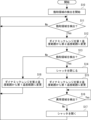
次に、実施の形態1にかかる画像処理装置100が行う処理について説明する。図2は、実施の形態1にかかる画像処理装置のフローチャートである。図2に示すフローチャートは、画像処理装置100がマイクロボロメータ900から撮像データを受け取ると開始される。なお、図2に示す処理を開始するにあたり、マイクロボロメータ900のダイナミックレンジは第1温度範囲(例えば10度から50度)に設定されている。なお、図2に示すフローチャートは、飽和領域検出部140、ダイナミックレンジ制御部150、画素修復判断部160およびシャッタ制御部170の処理を中心に説明しており、その他の構成の処理については適宜省略されている。ただし、各構成の処理や信号の流れについては、図1を参照して説明したとおりである。
Next, processing performed by the
まず、画像処理装置100は、マイクロボロメータ900から撮像データを受け取ると、飽和領域検出部140が飽和領域の検出を開始する(ステップS10)。次に、画像処理装置100は、撮像データに飽和領域を検出したか否かを判断する(ステップS11)。
First, when the
撮像データに飽和領域を検出したと判断しない場合(ステップS11:No)、画像処理装置100は、ステップS11を繰り返す。すなわち、画像処理装置100は、取得する撮像データに対して順次、飽和領域の検出を行う。
If it is not determined that a saturated region is detected in the image data (step S11: No), the
撮像データに飽和領域を検出したと判断した場合(ステップS11:Yes)、画像処理装置100は、ダイナミックレンジを第1温度範囲から第2温度範囲(例えば10度から200度)に変更する(ステップS12)。
If it is determined that a saturated region is detected in the imaging data (step S11: Yes), the
次に、画像処理装置100は、ダイナミックレンジを変更した後に生成された撮像データに対して、飽和領域を検出したか否かを判断する(ステップS13)。このような処理を行う理由は、第1温度範囲で飽和領域を検出した場合であっても、検出した飽和領域が太陽光によるものでない可能性があるからである。すなわち、ダイナミックレンジを第1温度範囲から第2温度範囲に広げた撮像データに対して飽和領域を検出することにより、画像処理装置100は、第1温度範囲で検出した飽和領域が太陽光によるものか否かを判断する。
Next, the
ダイナミックレンジを第2温度範囲に変更した後に生成された撮像データに対して、飽和領域を検出したと判断しない場合(ステップS13:No)、第1温度範囲で検出した飽和領域は、太陽光によるものではない。そこで、画像処理装置100は、ダイナミックレンジの設定を第2温度範囲から第1温度範囲に戻し(ステップS18)、再びステップS11に戻る。
If it is not determined that a saturated region has been detected in the imaging data generated after changing the dynamic range to the second temperature range (step S13: No), the saturated region detected in the first temperature range is due to sunlight. It's not a thing. Therefore, the
一方、ダイナミックレンジを第2温度範囲に変更した後に生成された撮像データに対して、飽和領域を検出したと判断する場合(ステップS13:Yes)、その飽和領域は太陽光によるものである。そこで、画像処理装置100は、シャッタ901を閉じる(ステップS14)。
On the other hand, if it is determined that a saturated region has been detected in the imaging data generated after changing the dynamic range to the second temperature range (step S13: Yes), the saturated region is due to sunlight. Therefore, the
次に、画像処理装置100は、ダイナミックレンジを、第2温度範囲から再び第1温度範囲に戻す(ステップS15)。さらに、画像処理装置100は、シャッタ901を閉じた状態で生成された撮像データに対して、異常領域が検出されるか否かを判断する(ステップS16)。
Next, the
シャッタ901を閉じた状態で生成された撮像データに異常領域が検出されると判断する場合(ステップS16:Yes)、画像処理装置100は、ステップS16を繰り返す。すなわち、画像処理装置100は、シャッタ901を閉じた状態の撮像データを順次取得し、取得した撮像データに対して異常領域が検出されるか否かを判断する。
When determining that an abnormal region is detected in the imaging data generated with the
一方、シャッタ901を閉じた状態で生成された撮像データに異常領域が検出されると判断しない場合(ステップS16:No)、画像処理装置100は、シャッタ901を開く(ステップS17)。ここで画像処理装置100がシャッタ901を開くのは、太陽光により異常状態となっていた撮像素子の異常状態が解消されたからである。画像処理装置100はシャッタ901を開いた後に、再びステップS11から処理を繰り返す。なお、ステップS15とステップS16は順序が逆でもよい。
On the other hand, if it is not determined that an abnormal region is detected in the imaging data generated with the
次に、熱画像の例を参照して、ダイナミックレンジの設定の違いについて説明する。図3は、実施の形態1にかかる画像処理装置が生成する画像の第1例を示す図である。図3には、画像処理装置100が生成する熱画像A11である。図3に示す熱画像A11は、マイクロボロメータ900のダイナミックレンジが第1温度範囲に設定されて撮像された例である。熱画像A11は、熱画像表示システム10を搭載した車両の進行方向を撮像したものである。熱画像A11は、他車両D11が含まれる。また他車両D11にはマフラーD12が含まれる。
Next, differences in dynamic range settings will be explained with reference to thermal image examples. FIG. 3 is a diagram showing a first example of an image generated by the image processing apparatus according to the first embodiment. FIG. 3 shows a thermal image A11 generated by the
熱画像A11は、物体が放射する電磁波を検出するため、熱の高い部分は明るく表示される。そのため、熱画像A11では、他車両D11が相対的に明るく表示されている。また他車両D11の中でも特に温度の高いマフラーD12は白く表示されている。熱画像A11で白く表示されているマフラーD12の輝度は飽和状態となっている。 Since the thermal image A11 detects electromagnetic waves emitted by the object, areas with high heat are displayed brightly. Therefore, in the thermal image A11, the other vehicle D11 is displayed relatively brightly. Furthermore, the muffler D12, which has a particularly high temperature among other vehicles D11, is displayed in white. The brightness of the muffler D12, which is displayed in white in the thermal image A11, is in a saturated state.
次に図4を参照して、ダイナミックレンジが第2温度範囲の場合の画像について説明する。図4は、実施の形態1にかかる画像処理装置が生成する画像の第2例を示す図である。図4に示す熱画像A12は、マイクロボロメータ900のダイナミックレンジが第1温度範囲より広い第2温度範囲に設定されて撮像された例である。
Next, referring to FIG. 4, an image when the dynamic range is in the second temperature range will be described. FIG. 4 is a diagram showing a second example of an image generated by the image processing apparatus according to the first embodiment. A thermal image A12 shown in FIG. 4 is an example in which the dynamic range of the
熱画像A12は、熱画像A11と比較すると、全体として明るい範囲が減少している。他車両D11もトーンが暗く表示され、マフラーD12は飽和状態ではなくなっている。 The bright range of the thermal image A12 is reduced as a whole compared to the thermal image A11. The other vehicle D11 is also displayed in a dark tone, and the muffler D12 is no longer saturated.
このように、ダイナミックレンジを第1温度範囲で撮像した場合に飽和状態となっていた領域は、ダイナミックレンジを第2温度範囲に変更することにより、飽和状態ではなくなっている。そのため、画像処理装置100は、シャッタ901を閉じることなく、再びダイナミックレンジを第1温度範囲に戻して撮像を継続できる。
In this way, the region that was saturated when the dynamic range was imaged in the first temperature range is no longer saturated by changing the dynamic range to the second temperature range. Therefore, the
次に、図5について説明する。図5は、実施の形態1にかかる画像処理装置が生成する画像の第3例を示す図である。図5に示す熱画像A13は、マイクロボロメータ900のダイナミックレンジが第1温度範囲に設定されて撮像された例である。熱画像A13は、他車両D11に加えて、画面の左上に太陽D13が含まれる。図5に示すように、太陽D13は、温度が高いため、白く表示されている。すなわち、太陽D13を表示する部分の輝度は飽和状態である。
Next, FIG. 5 will be explained. FIG. 5 is a diagram showing a third example of an image generated by the image processing apparatus according to the first embodiment. The thermal image A13 shown in FIG. 5 is an example in which the dynamic range of the
次に、図6について説明する。図6は、実施の形態1にかかる画像処理装置が生成する画像の第4例を示す図である。図6示す熱画像A14は、マイクロボロメータ900のダイナミックレンジが第2温度範囲に設定されて撮像された例である。
Next, FIG. 6 will be explained. FIG. 6 is a diagram showing a fourth example of an image generated by the image processing device according to the first embodiment. The thermal image A14 shown in FIG. 6 is an example in which the dynamic range of the
熱画像A14は、熱画像A13と比較すると、全体として明るい範囲が減少している。他車両D11もトーンが暗く表示され、マフラーD12は飽和状態ではなくなっている。一方、太陽D13は、飽和領域は少し減少しているものの、中心部分は飽和状態となっている。
The bright range of the thermal image A14 is reduced as a whole compared to the thermal image A13 . The other vehicle D11 is also displayed in a dark tone, and the muffler D12 is no longer saturated. On the other hand, although the saturated area of the sun D13 has decreased slightly, the central portion is still saturated.
このように、ダイナミックレンジを第1温度範囲で撮像した場合に、輝度が飽和状態となっていた領域のうち、太陽光については、ダイナミックレンジを第2温度範囲に変更しても飽和状態となっている。そのため、画像処理装置100は、太陽光の存在を適切に把握し、撮像素子を保護するためにシャッタを閉じる。
In this way, among the areas where the brightness was saturated when the dynamic range was imaged in the first temperature range, sunlight remained saturated even when the dynamic range was changed to the second temperature range. ing. Therefore, the
以上、実施の形態1について説明した。画像処理装置100は、上述のものに限られない。例えば、画像処理装置100は、上述の構成に加えて、マイクロボロメータ900、シャッタ901およびモニタ902のうち少なくともいずれか1つを含んでいても良い。画像処理装置100は、図1において説明した各構成が別個に設けられていてもよいし、複数の構成が一体となって構成されていてもよい。図1で説明した構成は、その一部が遠隔の地に設けられており、無線通信により上述の構成を実現するものであってもよい。
The first embodiment has been described above. The
上述のように、実施の形態1にかかる画像処理装置100は、ダイナミックレンジが第1温度範囲の状態において画素の飽和状態を検出した場合、ダイナミックレンジを第1温度範囲より広い第2温度範囲に変更することにより、太陽光を好適に検出できる。そのため、実施の形態1によれば、太陽光を適切に検出したうえで、太陽光から赤外線センサを保護する画像処理装置等を提供できる。
As described above, when the
<実施の形態2>
次に、実施の形態2について説明する。図7は、実施の形態2にかかる画像処理装置のブロック図である。図7には、実施の形態2にかかる熱画像表示システム10が示されている。熱画像表示システム10は、画像処理装置100に代えて、画像処理装置200を有している。画像処理装置200は、検出範囲設定部210を有する点が、画像処理装置100と異なる。
<Embodiment 2>
Next, a second embodiment will be described. FIG. 7 is a block diagram of an image processing device according to the second embodiment. FIG. 7 shows a thermal
欠陥画素補正部110は、マイクロボロメータ900から撮像データを受け取り、補正した撮像データを、画素不均一補正部120および検出範囲設定部210のそれぞれに供給する。
The defective
検出範囲設定部210は、飽和領域検出部140が飽和領域検出を行う範囲(検出範囲)を設定する。具体的には例えば、検出範囲設定部210は、欠陥画素補正部110から撮像データを受け取り、受け取った撮像データのうち、設定された一部分である検出範囲を切り出す。検出範囲は、予め定められた1つのものであってもよいし、所定の条件に応じて変動するものであってもよい。例えば、検出範囲設定部210は、時刻、天候、車両の姿勢および車両の進行方向のうち少なくとも1つをパラメータとして検出範囲を設定してもよい。検出範囲設定部210は、検出範囲を切り出すと、切り出した撮像データを飽和領域検出部140に供給する。よって、飽和領域検出部140は、受け取った撮像データの中から実施の形態1と同様に飽和領域を検出する。
The detection
次に、実施の形態2にかかる画像処理装置200の処理について説明する。図8は、実施の形態2にかかる画像処理装置のフローチャートである。
Next, processing of the
まず、画像処理装置200は、検出範囲を設定する(ステップS20)。画像処理装置200は、検出範囲を設定すると、次に、検出範囲に対して飽和領域の検出を開始する(ステップS10)。
First, the
次に、画像処理装置200は、撮像データの検出範囲内に飽和領域を検出したか否かを判断する(ステップS21)。検出範囲内に飽和領域を検出したと判断しない場合(ステップS21:No)、画像処理装置200は、ステップS21を繰り返す。すなわち、画像処理装置100は、取得する撮像データに対して順次、検出範囲内に対して飽和領域の検出を行う。検出範囲内に飽和領域を検出したと判断した場合(ステップS21:Yes)、画像処理装置100は、ダイナミックレンジを第1温度範囲から第2温度範囲(例えば10度から200度)に変更する(ステップS12)。
Next, the
次に、画像処理装置100は、ダイナミックレンジを変更した後に生成された撮像データの検出範囲に対して、飽和領域を検出したか否かを判断する(ステップS23)。ダイナミックレンジを第2温度範囲に変更した後に生成された撮像データの検出範囲に対して、飽和領域を検出したと判断しない場合(ステップS23:No)、第1温度範囲で検出した飽和領域は、太陽光によるものではない。そこで、画像処理装置200は、ダイナミックレンジの設定を第2温度範囲から第1温度範囲に戻し(ステップS18)、再びステップS21に戻る。
Next, the
一方、ダイナミックレンジを第2温度範囲に変更した後に生成された撮像データに対して、飽和領域を検出したと判断する場合(ステップS23:Yes)、その飽和領域は太陽光によるものである。そこで、画像処理装置100は、シャッタ901を閉じる(ステップS14)。ステップS14からステップS17までの処理は、実施の形態1で説明した処理と同様である。そのため、ここでは説明を省略する。
On the other hand, if it is determined that a saturated region has been detected in the imaging data generated after changing the dynamic range to the second temperature range (step S23: Yes), the saturated region is due to sunlight. Therefore, the
以上に説明した処理により、実施の形態2にかかる画像処理装置200は、設定された検出範囲に対して飽和領域の検出を行う。よって、画像処理装置200は、高速に処理を実行できる。なお、ステップS20の処理は、画像処理装置200がマイクロボロメータ900から撮像データを取得する前に行われてもよい。
Through the processing described above, the
次に、熱画像の例を参照して、検出範囲の設定についてさらに説明する。図9は、実施の形態2にかかる画像処理装置が検出する画像の例を示す図である。図9は、画像処理装置200が生成する熱画像A21である。図9に示す熱画像A21は、マイクロボロメータ900のダイナミックレンジが第1温度範囲に設定されて撮像された例である。熱画像A21には、他車両D11、マフラーD12および、太陽D13が含まれる。図9に示すように、マフラーD12および太陽D13は、比較的に温度が高いため、白く表示されている。すなわち、マフラーD12および太陽D13を表示する部分の輝度は飽和状態である。
Next, setting the detection range will be further explained with reference to an example of a thermal image. FIG. 9 is a diagram illustrating an example of an image detected by the image processing apparatus according to the second embodiment. FIG. 9 shows a thermal image A21 generated by the
図9には、検出範囲R21が示されている。図9において一点鎖線により示された矩形は、検出範囲R21を画定する境界線を示している。すなわち、検出範囲R21は、一点鎖線により示された矩形の内側の範囲である。図9に示された検出範囲R21は、熱画像A21の鉛直方向上側40パーセント程の範囲である。すなわち、画像処理装置200は、撮像データから切り出された検出範囲R21について、飽和領域の検出を行う。そのため、画像処理装置200は、マフラーD12を飽和領域として検出することなく、太陽D13が撮像された領域について、上述の処理を行う。
FIG. 9 shows a detection range R21. A rectangle indicated by a dashed line in FIG. 9 indicates a boundary line defining the detection range R21. That is, the detection range R21 is the range inside the rectangle indicated by the dashed line. The detection range R21 shown in FIG. 9 is a range of about 40% above the thermal image A21 in the vertical direction. That is, the
なお、上述の検出範囲の設定において、検出範囲設定部210は、検出範囲がない状態(つまり、検出範囲を切り出さない状態)を設定できる。また、上述の検出範囲の設定において、検出範囲設定部210は、時刻、天候、車両の姿勢および車両の進行方向のうち少なくとも1つをパラメータとして検出範囲を設定してもよい。
Note that in setting the detection range described above, the detection
例えば検出範囲設定部210は、太陽が出現しない時刻では、検出範囲がない状態を設定してもよい。また検出範囲設定部210は、天候情報を取得し、雨天の場合には検出範囲がない状態を設定してもよい。また検出範囲設定部210は、太陽の位置が比較的に低い朝や夕方は検出範囲を熱画像A21の下側に広げ、太陽の位置が比較的に高い昼間は検出範囲を熱画像A21の上側に狭めてもよい。また、検出範囲設定部210は、車両の姿勢を検出し、坂を上っている場合には検出範囲を広げ、坂を下っている場合には検出範囲を狭くしてもよい。また、検出範囲設定部210は、時刻情報と車両の進行方向とを検出し、例えば午前中に東に向かって走行している場合には検出範囲を広く設定し、午前中に西に向かって走行している場合には検出範囲がない状態を設定してもよい。
For example, the detection
上述のように、実施の形態2にかかる画像処理装置200は、ダイナミックレンジが第1温度範囲の状態において画素の飽和状態を検出した場合、ダイナミックレンジを第1温度範囲より広い第2温度範囲に変更することにより、太陽光を好適に検出できる。また画像処理装置200は、検出範囲を設定することにより、効率よく太陽光を検出できる。そのため、実施の形態2によれば、太陽光を適切に検出したうえで、太陽光から赤外線センサを保護する画像処理装置等を提供できる。
As described above, when the
なお、上述したプログラムは、様々なタイプの非一時的なコンピュータ可読媒体を用いて格納され、コンピュータに供給することができる。非一時的なコンピュータ可読媒体は、様々なタイプの実体のある記録媒体を含む。非一時的なコンピュータ可読媒体の例は、磁気記録媒体(例えばフレキシブルディスク、磁気テープ、ハードディスクドライブ)、光磁気記録媒体(例えば光磁気ディスク)、CD-ROM(Read Only Memory)CD-R、CD-R/W、半導体メモリ(例えば、マスクROM、PROM(Programmable ROM)、EPROM(Erasable PROM)、フラッシュROM、RAM(Random Access Memory))を含む。また、プログラムは、様々なタイプの一時的なコンピュータ可読媒体によってコンピュータに供給されてもよい。一時的なコンピュータ可読媒体の例は、電気信号、光信号、及び電磁波を含む。一時的なコンピュータ可読媒体は、電線及び光ファイバ等の有線通信路、又は無線通信路を介して、プログラムをコンピュータに供給できる。 Note that the programs described above can be stored and provided to a computer using various types of non-transitory computer-readable media. Non-transitory computer-readable media includes various types of tangible storage media. Examples of non-transitory computer-readable media include magnetic recording media (e.g., flexible disks, magnetic tape, hard disk drives), magneto-optical recording media (e.g., magneto-optical disks), CD-ROMs (Read Only Memory), CD-Rs, and CDs. - R/W, semiconductor memory (for example, mask ROM, PROM (Programmable ROM), EPROM (Erasable PROM), flash ROM, RAM (Random Access Memory)). The program may also be provided to the computer on various types of temporary computer-readable media. Examples of transitory computer-readable media include electrical signals, optical signals, and electromagnetic waves. The temporary computer-readable medium can provide the program to the computer via wired communication channels, such as electrical wires and fiber optics, or wireless communication channels.
なお、本発明は上記実施の形態に限られたものではなく、趣旨を逸脱しない範囲で適宜変更することが可能である。例えば、画像処理装置は、自動車に限らず、バイク、船、飛行機、移動ロボット、ドローンなどの移動体に適用可能である。 Note that the present invention is not limited to the above embodiments, and can be modified as appropriate without departing from the spirit. For example, the image processing device is applicable not only to automobiles but also to moving objects such as motorcycles, ships, airplanes, mobile robots, and drones.
10 熱画像表示システム
100、200 画像処理装置
110 欠陥画素補正部
120 画素不均一補正部
130 AGC処理部
140 飽和領域検出部
150 ダイナミックレンジ制御部
160 画素修復判断部
170 シャッタ制御部
210 検出範囲設定部
900 マイクロボロメータ
901 シャッタ
902 モニタ
A11、A12、A13、A14、A21 熱画像
D11 他車両
D12 マフラー
D13 太陽
R21 検出範囲
10 Thermal
Claims (6)
前記飽和領域の検出結果に応じて前記赤外線撮像素子が検出する温度範囲であるダイナミックレンジを、他車両の温度で上限値側が飽和状態となる第1温度範囲または第1温度範囲より少なくとも上限値側の温度が高く他車両の温度で飽和状態とはならない第2温度範囲に設定するダイナミックレンジ制御部と、
前記飽和領域の検出結果および前記ダイナミックレンジの設定に基づいて前記赤外線撮像素子を保護するためのシャッタの開閉を制御するシャッタ制御部と、を備え、
前記ダイナミックレンジ制御部は、前記ダイナミックレンジの設定が前記第1温度範囲のときに前記飽和領域検出部が前記飽和領域を検出した場合に、前記ダイナミックレンジの設定を前記第1温度範囲から前記第2温度範囲に変更し、前記ダイナミックレンジが前記第2温度範囲に設定された状態で前記飽和領域検出部が前記飽和領域を検出しない場合は、前記ダイナミックレンジの設定を前記第2温度範囲から前記第1温度範囲に変更し、
前記シャッタ制御部は、前記ダイナミックレンジが前記第2温度範囲に設定された状態、かつ、前記飽和領域検出部が前記飽和領域を検出した場合に、シャッタを閉じる、
画像処理装置。 a saturated region detection unit that acquires imaging data from an infrared imaging device that captures a thermal image around the moving object, and detects that a saturated region exists in the imaging data;
The dynamic range , which is the temperature range detected by the infrared imaging device according to the detection result of the saturation region , is set to a first temperature range in which the upper limit side is saturated at the temperature of another vehicle, or at least closer to the upper limit value than the first temperature range. a dynamic range control unit that sets the temperature to a second temperature range in which the temperature of the vehicle is high and the temperature of the other vehicle is not saturated ;
a shutter control unit that controls opening and closing of a shutter for protecting the infrared imaging device based on the detection result of the saturation region and the dynamic range setting ,
The dynamic range control section changes the dynamic range setting from the first temperature range to the first temperature range when the saturated region detection section detects the saturated region when the dynamic range setting is within the first temperature range. If the dynamic range is set to the second temperature range and the saturated region detection section does not detect the saturated region, the dynamic range setting is changed from the second temperature range to the second temperature range. Change to the first temperature range,
The shutter control section closes the shutter when the dynamic range is set to the second temperature range and the saturated region detection section detects the saturated region.
Image processing device.
請求項1に記載の画像処理装置。 The dynamic range control unit sets an upper limit of the temperature range detected by the infrared imaging device to 50 degrees as the first temperature range, and sets an upper limit of the temperature range detected by the infrared imaging device as the second temperature range. Set it so that it is 200 degrees,
The image processing device according to claim 1.
請求項1または2に記載の画像処理装置。The image processing device according to claim 1 or 2.
前記検出範囲設定部は、時刻、天候、前記移動体の姿勢および前記移動体の進行方向のうち少なくとも1つをパラメータとして前記検出範囲を設定するThe detection range setting unit sets the detection range using at least one of time, weather, attitude of the moving object, and direction of movement of the moving object as a parameter.
請求項1~3のいずれか一項に記載の画像処理装置。The image processing device according to any one of claims 1 to 3.
前記撮像データに飽和領域が存在することを検出する飽和領域検出ステップと、a saturated region detection step of detecting that a saturated region exists in the imaged data;
前記飽和領域の検出結果に応じて前記赤外線撮像素子が検出する温度範囲であるダイナミックレンジを、他車両の温度で上限値側が飽和状態となる第1温度範囲または第1温度範囲より少なくとも上限値側の温度が高く他車両の温度で飽和状態とならない第2温度範囲に設定するダイナミックレンジ制御ステップと、The dynamic range, which is the temperature range detected by the infrared imaging device according to the detection result of the saturation region, is set to a first temperature range in which the upper limit side is saturated at the temperature of another vehicle, or at least closer to the upper limit value than the first temperature range. a dynamic range control step of setting a second temperature range in which the temperature of the vehicle is high and does not become saturated with the temperature of other vehicles;
前記飽和領域の検出結果および前記ダイナミックレンジの設定に基づいて前記赤外線撮像素子を保護するためのシャッタの開閉を制御するシャッタ制御ステップと、を備え、a shutter control step of controlling opening and closing of a shutter for protecting the infrared imaging device based on the detection result of the saturation region and the dynamic range setting,
前記ダイナミックレンジ制御ステップは、前記ダイナミックレンジの設定が前記第1温度範囲のときに前記飽和領域検出ステップで前記飽和領域を検出した場合に、前記ダイナミックレンジの設定を前記第1温度範囲から前記第2温度範囲に変更し、前記ダイナミックレンジが前記第2温度範囲に設定された状態において前記飽和領域検出ステップで前記飽和領域を検出しない場合は、前記ダイナミックレンジの設定を前記第2温度範囲から前記第1温度範囲に変更し、The dynamic range control step changes the dynamic range setting from the first temperature range to the first temperature range when the saturated region is detected in the saturated region detection step when the dynamic range setting is within the first temperature range. If the dynamic range is set to the second temperature range and the saturated region is not detected in the saturated region detection step, the dynamic range setting is changed from the second temperature range to the second temperature range. Change to the first temperature range,
前記シャッタ制御ステップは、前記ダイナミックレンジが前記第2温度範囲に設定された状態、かつ、前記飽和領域検出ステップで前記飽和領域を検出した場合に、シャッタを閉じる、The shutter control step closes the shutter when the dynamic range is set to the second temperature range and the saturated region is detected in the saturated region detection step.
画像処理方法。Image processing method.
前記撮像データに飽和領域が存在することを検出する飽和領域検出ステップと、a saturated region detection step of detecting that a saturated region exists in the imaged data;
前記飽和領域の検出結果に応じて前記赤外線撮像素子が検出する温度範囲であるダイナミックレンジを、他車両の温度で上限値側が飽和状態となる第1温度範囲または第1温度範囲より少なくとも上限値側の温度が高く他車両の温度で飽和状態とならない第2温度範囲に設定するダイナミックレンジ制御ステップと、The dynamic range, which is the temperature range detected by the infrared imaging device according to the detection result of the saturation region, is set to a first temperature range in which the upper limit side is saturated at the temperature of another vehicle, or at least closer to the upper limit value than the first temperature range. a dynamic range control step of setting a second temperature range in which the temperature of the vehicle is high and does not become saturated with the temperature of other vehicles;
前記飽和領域の検出結果および前記ダイナミックレンジの設定に基づいて前記赤外線撮像素子を保護するためのシャッタの開閉を制御するシャッタ制御ステップと、を備え、a shutter control step of controlling opening and closing of a shutter for protecting the infrared imaging device based on the detection result of the saturation region and the dynamic range setting,
前記ダイナミックレンジ制御ステップは、前記ダイナミックレンジの設定が前記第1温度範囲のときに前記飽和領域検出ステップで前記飽和領域を検出した場合に、前記ダイナミックレンジの設定を前記第1温度範囲から前記第2温度範囲に変更し、前記ダイナミックレンジが前記第2温度範囲に設定された状態において前記飽和領域検出ステップで前記飽和領域を検出しない場合は、前記ダイナミックレンジの設定を前記第2温度範囲から前記第1温度範囲に変更し、The dynamic range control step changes the dynamic range setting from the first temperature range to the first temperature range when the saturated region is detected in the saturated region detection step when the dynamic range setting is within the first temperature range. If the dynamic range is set to the second temperature range and the saturated region is not detected in the saturated region detection step, the dynamic range setting is changed from the second temperature range to the second temperature range. Change to the first temperature range,
前記シャッタ制御ステップは、前記ダイナミックレンジが前記第2温度範囲に設定された状態、かつ、前記飽和領域検出ステップで前記飽和領域を検出した場合に、シャッタを閉じる、The shutter control step closes the shutter when the dynamic range is set to the second temperature range and the saturated region is detected in the saturated region detection step.
画像処理方法を、コンピュータに実行させるプログラム。A program that causes a computer to execute an image processing method.
Priority Applications (4)
| Application Number | Priority Date | Filing Date | Title |
|---|---|---|---|
| JP2020000410A JP7375552B2 (en) | 2020-01-06 | 2020-01-06 | Image processing device, image processing method and program |
| PCT/JP2020/039486 WO2021140721A1 (en) | 2020-01-06 | 2020-10-21 | Image processing device, image processing method, and program |
| CN202080079707.XA CN114746727B (en) | 2020-01-06 | 2020-10-21 | Image processing device, image processing method and storage medium |
| US17/833,332 US11936997B2 (en) | 2020-01-06 | 2022-06-06 | Image processing apparatus, image processing method, and non-transitory computer readable medium |
Applications Claiming Priority (1)
| Application Number | Priority Date | Filing Date | Title |
|---|---|---|---|
| JP2020000410A JP7375552B2 (en) | 2020-01-06 | 2020-01-06 | Image processing device, image processing method and program |
Publications (3)
| Publication Number | Publication Date |
|---|---|
| JP2021110552A JP2021110552A (en) | 2021-08-02 |
| JP2021110552A5 JP2021110552A5 (en) | 2022-09-12 |
| JP7375552B2 true JP7375552B2 (en) | 2023-11-08 |
Family
ID=76788659
Family Applications (1)
| Application Number | Title | Priority Date | Filing Date |
|---|---|---|---|
| JP2020000410A Active JP7375552B2 (en) | 2020-01-06 | 2020-01-06 | Image processing device, image processing method and program |
Country Status (4)
| Country | Link |
|---|---|
| US (1) | US11936997B2 (en) |
| JP (1) | JP7375552B2 (en) |
| CN (1) | CN114746727B (en) |
| WO (1) | WO2021140721A1 (en) |
Families Citing this family (6)
| Publication number | Priority date | Publication date | Assignee | Title |
|---|---|---|---|---|
| WO2021226408A1 (en) * | 2020-05-08 | 2021-11-11 | Flir Commercial Systems, Inc. | Burn-in mitigation and associated imaging systems and methods |
| JP7494615B2 (en) * | 2020-07-22 | 2024-06-04 | 株式会社Jvcケンウッド | Image processing device, image processing method, and program |
| JP7673589B2 (en) * | 2021-08-26 | 2025-05-09 | 株式会社Jvcケンウッド | Control Systems and Programs |
| JP2023074749A (en) * | 2021-11-18 | 2023-05-30 | 株式会社Jvcケンウッド | Control system and control method |
| JP2023130734A (en) * | 2022-03-08 | 2023-09-21 | 株式会社Jvcケンウッド | Image processing device, image processing method, and program |
| CN116091959B (en) * | 2022-11-21 | 2024-03-22 | 武汉坤达安信息安全技术有限公司 | Double-light linkage identification method and device based on all-weather smoke and fire |
Citations (6)
| Publication number | Priority date | Publication date | Assignee | Title |
|---|---|---|---|---|
| JP2001356047A (en) | 2000-06-14 | 2001-12-26 | Hochiki Corp | Flame detection device and detection sensitivity setting method thereof |
| JP2010226652A (en) | 2009-03-25 | 2010-10-07 | Zenrin Co Ltd | Image processing apparatus, image processing method, and computer program |
| CN102889932A (en) | 2012-09-25 | 2013-01-23 | 山东神戎电子股份有限公司 | Thermal imager and method for resisting strong-light damage |
| US8957373B1 (en) | 2013-01-28 | 2015-02-17 | Carlo L. Tiana | Artifact prevention system, device, and method for an electromagnetic imaging system |
| US9102776B1 (en) | 2012-03-05 | 2015-08-11 | Flir Systems, Inc. | Detection and mitigation of burn-in for thermal imaging systems |
| US20190364218A1 (en) | 2017-01-17 | 2019-11-28 | Hangzhou Hikvision Digital Technology Co., Ltd. | Method and Apparatus for Protecting Device Under Strong Light |
Family Cites Families (8)
| Publication number | Priority date | Publication date | Assignee | Title |
|---|---|---|---|---|
| JPH08240833A (en) * | 1995-03-02 | 1996-09-17 | Mitsubishi Electric Corp | Exposure control device for vehicle camera |
| US6521892B2 (en) * | 1998-10-09 | 2003-02-18 | Thomson-Csf Optronics Canada Inc. | Uncooled driver viewer enhancement system |
| US7772557B2 (en) * | 2007-03-29 | 2010-08-10 | Fluke Corporation | Offset compensation scheduling algorithm for infrared imagers |
| JP2009005120A (en) * | 2007-06-22 | 2009-01-08 | Sony Corp | Far infrared imaging device and far infrared imaging method |
| WO2014082097A1 (en) * | 2012-11-26 | 2014-05-30 | Flir Systems, Inc. | Hybrid infrared sensor array having heterogeneous infrared sensors |
| WO2016052417A1 (en) * | 2014-09-29 | 2016-04-07 | 富士フイルム株式会社 | Infrared image acquisition device and infrared image acquisition method |
| JP6629700B2 (en) * | 2016-09-28 | 2020-01-15 | 京セラ株式会社 | Image processing device, imaging device, moving object, and image processing method |
| US11012594B2 (en) * | 2017-06-05 | 2021-05-18 | Adasky, Ltd. | Techniques for correcting oversaturated pixels in shutterless FIR cameras |
-
2020
- 2020-01-06 JP JP2020000410A patent/JP7375552B2/en active Active
- 2020-10-21 WO PCT/JP2020/039486 patent/WO2021140721A1/en not_active Ceased
- 2020-10-21 CN CN202080079707.XA patent/CN114746727B/en active Active
-
2022
- 2022-06-06 US US17/833,332 patent/US11936997B2/en active Active
Patent Citations (6)
| Publication number | Priority date | Publication date | Assignee | Title |
|---|---|---|---|---|
| JP2001356047A (en) | 2000-06-14 | 2001-12-26 | Hochiki Corp | Flame detection device and detection sensitivity setting method thereof |
| JP2010226652A (en) | 2009-03-25 | 2010-10-07 | Zenrin Co Ltd | Image processing apparatus, image processing method, and computer program |
| US9102776B1 (en) | 2012-03-05 | 2015-08-11 | Flir Systems, Inc. | Detection and mitigation of burn-in for thermal imaging systems |
| CN102889932A (en) | 2012-09-25 | 2013-01-23 | 山东神戎电子股份有限公司 | Thermal imager and method for resisting strong-light damage |
| US8957373B1 (en) | 2013-01-28 | 2015-02-17 | Carlo L. Tiana | Artifact prevention system, device, and method for an electromagnetic imaging system |
| US20190364218A1 (en) | 2017-01-17 | 2019-11-28 | Hangzhou Hikvision Digital Technology Co., Ltd. | Method and Apparatus for Protecting Device Under Strong Light |
Also Published As
| Publication number | Publication date |
|---|---|
| WO2021140721A1 (en) | 2021-07-15 |
| CN114746727A (en) | 2022-07-12 |
| US11936997B2 (en) | 2024-03-19 |
| JP2021110552A (en) | 2021-08-02 |
| CN114746727B (en) | 2025-05-02 |
| US20220377263A1 (en) | 2022-11-24 |
Similar Documents
| Publication | Publication Date | Title |
|---|---|---|
| JP7375552B2 (en) | Image processing device, image processing method and program | |
| US10469747B2 (en) | Infrared imaging device and signal correction method using infrared imaging device | |
| JP2020522937A (en) | Shutterless Far Infrared (FIR) Camera for Automotive Safety and Driving Systems | |
| CN115211098B (en) | Image processing apparatus, image processing method, and storage medium | |
| US20180131877A1 (en) | Image display device for vehicle and image display program for vehicle | |
| US12101569B2 (en) | Techniques for correcting oversaturated pixels in shutterless FIR cameras | |
| KR20120056214A (en) | Imaging apparatus, image processing method and computer-readable storage medium | |
| JP2020136900A (en) | Imaging device, image recording device, and imaging method | |
| US10699386B2 (en) | Techniques for scene-based nonuniformity correction in shutterless FIR cameras | |
| KR20120053764A (en) | Apparatus for processing image of camera in vehicle and method thereof | |
| JP7673589B2 (en) | Control Systems and Programs | |
| JP7213732B2 (en) | image display device | |
| JP3882640B2 (en) | Infrared camera | |
| KR20110067700A (en) | Image Acquisition Method and Digital Camera System | |
| WO2024171810A1 (en) | Image processing device, image processing method, and program | |
| US20240414445A1 (en) | Image processing apparatus, image processing method, and non-transitory computer-readable medium | |
| US12423868B2 (en) | Control system and control method | |
| JP2026002334A (en) | Image processing device and sensor protection method | |
| JP2022187078A (en) | Control system, control method, and program | |
| JP2025065909A (en) | Image processing device and image processing method | |
| JP2024162443A (en) | Image processing device and image processing method | |
| JP2024079035A (en) | Imaging system, blur detection method, and program | |
| JP2024162036A (en) | Image processing device and image processing method | |
| KR20110064218A (en) | Defective pixel correction device and method |
Legal Events
| Date | Code | Title | Description |
|---|---|---|---|
| A521 | Request for written amendment filed |
Free format text: JAPANESE INTERMEDIATE CODE: A523 Effective date: 20220902 |
|
| A621 | Written request for application examination |
Free format text: JAPANESE INTERMEDIATE CODE: A621 Effective date: 20221228 |
|
| TRDD | Decision of grant or rejection written | ||
| A01 | Written decision to grant a patent or to grant a registration (utility model) |
Free format text: JAPANESE INTERMEDIATE CODE: A01 Effective date: 20230926 |
|
| A61 | First payment of annual fees (during grant procedure) |
Free format text: JAPANESE INTERMEDIATE CODE: A61 Effective date: 20231009 |
|
| R150 | Certificate of patent or registration of utility model |
Ref document number: 7375552 Country of ref document: JP Free format text: JAPANESE INTERMEDIATE CODE: R150 |