EP3573237A1 - Set of plates of electronic multichannel touch wall switch - Google Patents
Set of plates of electronic multichannel touch wall switch Download PDFInfo
- Publication number
- EP3573237A1 EP3573237A1 EP19175275.7A EP19175275A EP3573237A1 EP 3573237 A1 EP3573237 A1 EP 3573237A1 EP 19175275 A EP19175275 A EP 19175275A EP 3573237 A1 EP3573237 A1 EP 3573237A1
- Authority
- EP
- European Patent Office
- Prior art keywords
- board
- light guide
- microprocessor
- sensors
- wall switch
- Prior art date
- Legal status (The legal status is an assumption and is not a legal conclusion. Google has not performed a legal analysis and makes no representation as to the accuracy of the status listed.)
- Withdrawn
Links
- 230000000873 masking effect Effects 0.000 claims abstract description 22
- 239000000463 material Substances 0.000 claims abstract description 6
- 239000007787 solid Substances 0.000 claims abstract description 4
- 239000000835 fiber Substances 0.000 claims abstract description 3
- 238000009434 installation Methods 0.000 claims abstract description 3
- 239000013307 optical fiber Substances 0.000 claims description 2
- 238000004519 manufacturing process Methods 0.000 description 4
- 238000002347 injection Methods 0.000 description 3
- 239000007924 injection Substances 0.000 description 3
- 230000008901 benefit Effects 0.000 description 2
- 239000003086 colorant Substances 0.000 description 2
- 230000003111 delayed effect Effects 0.000 description 2
- 238000001514 detection method Methods 0.000 description 2
- 239000000243 solution Substances 0.000 description 2
- 229910000831 Steel Inorganic materials 0.000 description 1
- 230000006978 adaptation Effects 0.000 description 1
- 238000005266 casting Methods 0.000 description 1
- 230000000694 effects Effects 0.000 description 1
- 239000012467 final product Substances 0.000 description 1
- 239000003292 glue Substances 0.000 description 1
- 238000003780 insertion Methods 0.000 description 1
- 230000037431 insertion Effects 0.000 description 1
- 230000003993 interaction Effects 0.000 description 1
- 238000005259 measurement Methods 0.000 description 1
- 230000009467 reduction Effects 0.000 description 1
- 238000000926 separation method Methods 0.000 description 1
- 238000004088 simulation Methods 0.000 description 1
- 239000010959 steel Substances 0.000 description 1
Images


Classifications
-
- H—ELECTRICITY
- H03—ELECTRONIC CIRCUITRY
- H03K—PULSE TECHNIQUE
- H03K17/00—Electronic switching or gating, i.e. not by contact-making and –breaking
- H03K17/94—Electronic switching or gating, i.e. not by contact-making and –breaking characterised by the way in which the control signals are generated
- H03K17/96—Touch switches
- H03K17/962—Capacitive touch switches
- H03K17/9622—Capacitive touch switches using a plurality of detectors, e.g. keyboard
-
- G—PHYSICS
- G02—OPTICS
- G02B—OPTICAL ELEMENTS, SYSTEMS OR APPARATUS
- G02B6/00—Light guides; Structural details of arrangements comprising light guides and other optical elements, e.g. couplings
- G02B6/0001—Light guides; Structural details of arrangements comprising light guides and other optical elements, e.g. couplings specially adapted for lighting devices or systems
- G02B6/0011—Light guides; Structural details of arrangements comprising light guides and other optical elements, e.g. couplings specially adapted for lighting devices or systems the light guides being planar or of plate-like form
- G02B6/0013—Means for improving the coupling-in of light from the light source into the light guide
- G02B6/0015—Means for improving the coupling-in of light from the light source into the light guide provided on the surface of the light guide or in the bulk of it
- G02B6/002—Means for improving the coupling-in of light from the light source into the light guide provided on the surface of the light guide or in the bulk of it by shaping at least a portion of the light guide, e.g. with collimating, focussing or diverging surfaces
- G02B6/0021—Means for improving the coupling-in of light from the light source into the light guide provided on the surface of the light guide or in the bulk of it by shaping at least a portion of the light guide, e.g. with collimating, focussing or diverging surfaces for housing at least a part of the light source, e.g. by forming holes or recesses
-
- G—PHYSICS
- G02—OPTICS
- G02B—OPTICAL ELEMENTS, SYSTEMS OR APPARATUS
- G02B6/00—Light guides; Structural details of arrangements comprising light guides and other optical elements, e.g. couplings
- G02B6/0001—Light guides; Structural details of arrangements comprising light guides and other optical elements, e.g. couplings specially adapted for lighting devices or systems
- G02B6/0011—Light guides; Structural details of arrangements comprising light guides and other optical elements, e.g. couplings specially adapted for lighting devices or systems the light guides being planar or of plate-like form
- G02B6/0075—Arrangements of multiple light guides
-
- H—ELECTRICITY
- H03—ELECTRONIC CIRCUITRY
- H03K—PULSE TECHNIQUE
- H03K2217/00—Indexing scheme related to electronic switching or gating, i.e. not by contact-making or -breaking covered by H03K17/00
- H03K2217/94—Indexing scheme related to electronic switching or gating, i.e. not by contact-making or -breaking covered by H03K17/00 characterised by the way in which the control signal is generated
- H03K2217/96—Touch switches
- H03K2217/96054—Double function: touch detection combined with detection of a movable element
-
- H—ELECTRICITY
- H03—ELECTRONIC CIRCUITRY
- H03K—PULSE TECHNIQUE
- H03K2217/00—Indexing scheme related to electronic switching or gating, i.e. not by contact-making or -breaking covered by H03K17/00
- H03K2217/94—Indexing scheme related to electronic switching or gating, i.e. not by contact-making or -breaking covered by H03K17/00 characterised by the way in which the control signal is generated
- H03K2217/96—Touch switches
- H03K2217/9607—Capacitive touch switches
- H03K2217/960785—Capacitive touch switches with illumination
- H03K2217/96079—Capacitive touch switches with illumination using a single or more light guides
Definitions
- the presented invention relates to a set of boards of a wall switch for electrical appliances with touch or proximity sensors and backlighted icons.
- the wall switches manufactured by LIVOLO comprise front plate with only two graphic icons indicating locations of each touch area and only four LED diodes soldered on back Printed Circuit Board, two per each extruded light guide shape backlighting the dedicated icon to be backlighted.
- the LIVOLO offer of touch wall switches with replaceable decorative front frames is limited to very small number of colors, sizes and surface textures offered by the manufacturer, restricting and hindering the possibilities of interior design.
- the purpose of the presented invention was a creation of possibility of controlling more electrical receivers by finding the way how to increase the number of individually backlighted graphic icons without the needs of increasing mechanical dimensions of touch wall switch panel and simultaneously preventing leaking of the light which backlights one icon towards adjacent icons, enabling cooperation the new touch wall switch with any commercially available home control system of any manufacturer, especially of Smart Home market as well as significant new touch wall switch manufacturing cost reductions and simultaneously extending possibilities of usage a different combinations of colors, mechanical proportions, sizes and textures of decorative masking frames and front icon plates.
- the essence of the set of boards according to the invention composed of terminals board with power commutation switches and power supply unit, main microprocessor board, fitting bridge, decorative masking frame, sensors board comprising touch or proximity sensors with their controller and set of electroluminescent LED diodes with their controller as well as passive sensors namely ambient light sensor and infrared light sensor, light guide plate with back reflective layer and front dielectric layer with backlighted graphic icons and all the above mentioned elements having an interconnection means - is that the light guide plate is divided by a gaps, slits or slots creating required number of separate light guide cells and each gap is filled with reflective material creating the side walls of the light guide cells, whereby so constructed light guide plate is stacked with back reflective layer and front dielectric backlighted graphic layer as a solid fiber optic light guide panel, which along with the sensors board is inserted into decorative masking frame window.
- sensors board contains an infrared light receiver module acquiring the remote control signals and the ambient light sensor integrated with the rangefinder made as a single integrated module using infrared wavelength band.
- the main microprocessor board has breakable perforated side outlets with mounting holes facilitating the installation of microprocessor board in known commercially available mounting bridge, whereby the sensors board and backlighted light guide panel have an identical shape and outer size adjusted to the window of the decorative masking frame of any choice.
- the microprocessor board has an extension connector for communication with external devices as well as a radio communication module and a electroluminescent LED diodes on sensor's board are tricolor LEDs.
- One of the benefits of such a solution presented herein is a possibility of significant increasing the number of light cells and so the number of controlled electric appliances while keeping small size of the front backlighted light guide panel and the touch-proximity sensors board.
- Second and most important advantage is a possibility of using variety of decorative masking frames and mounting bridges already available on the market, so that the needs of manufacturing various variants of injection molds with their very high costs are eliminated. It is achievable mainly due to breakable perforated side outlets on microprocessor bard which allow mounting the whole boards stackup as well as the size adaptations of abovementioned boards and light guide panels to wide choice of known elements available on the market.
- the rangefinder allows sensing the human hand approaching towards the front touch panel, which is advantageous when the hand "search” the touch panel in the dark for instance.
- the presented invented touch wall switch can backlight the panel for more comfortable usage.
- the external communication connector incorporated in the set according to the presented invention allows connecting and integrating the new touch wall switch with external devices and whole third-party control systems of any manufacturer for instance of Smart Home market and no known commercially available wall switch on the market offers it at present.
- the presented touch wall switch has gained an ability to execute many more additional utility functions like household persons simulation, delayed switching off the channels and so on.
- the wall switch will maintain the light On and then will turn the light Off after the predefined time period.
- this user activity may cause a broadcast network message to other presented touch wall switches cooperating in the local network resulting in a different actions on the remote associated device, which is important for instance when arranging the light scenes.
- tricolor RGB electroluminescent LED diodes D instead of single color diodes along with the supervising dedicated LED controller, enabled dynamically changing the backlight color and intensity as well as to enrich the graphic icons backlighting in any desirable color, which in turn allows the device to communicate interactively with the user by color coded messages and informing the user about the device internal state or working mode of any particular touch pad and channel.
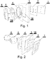
- the presented invention of wall switch module consists of integrated concrete backlighted and replaceable light guide panel 1 , sensors board 2 , decorative masking frame 3 , mounting bridge 4 , microprocessor board 5 and finally terminals board with power commutation switches and power supply unit.
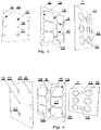
- Light guide panel 1 comprise the dielectric front graphic layer 7 , inner light guide plate 8 and back reflective layer 9 .
- Front layer 7 has semitransparent graphic icons 10 , fully transparent window 11 for infrared receiver module SP and another fully transparent window 12 for ambient light sensor with infrared rangefinder MS as an integrated module.
- the light guide plate 8 has a form of dispersive dielectric sheet divided by a gaps, slits or slots filled with reflective material into six optical fiber light guide cells 13 , whereby the gaps filled with reflective material create the reflective side walls 14 of the light guide cells 13 .
- Reflective back layer 9 has a hole 19 for a screw, through-holes 20 for LED diodes D , through-holes 21 for ambient light sensor with rangefinder MS and through-hole 22 for infrared receiver module SP .
- Front side of the sensors board 2 is soldered with six tricolor electroluminescent RGB LED diodes D in the number corresponding to the number of fiber-optic light guide cells 13 made in light guide panel, soldered with infrared receiver SP and integrated ambient light sensor with rangefinder MS , capacitive toch-proximity sensors SZ and the hole 23 coaxial with the mounting screw 15 for fastening the sensors board 2 to light guide panel 1 .
- Microprocessor board 5 contains a microprocessor 27 , fastening rods 28 corresponding to the sockets 26 on sensors board 2 , connector 29 for communication with external devices as well as a connector 30 allowing connection to the terminals and power commutation switches board 6 .
- the microprocessor board 5 may have a radio communication module M and breakable perforated side outlets 31 with mounting holes 32 and 33 or side inlets 34 allowing easy interconnecting with the bridge 4 depending on the chosen market available bridge 4 type.
- Terminals and power commutation switches board 6 consists of rods 35 for connection with sockets 30 of microprocessor board 5 , power supply circuit Z , power cables connector 36 and a power commutation switches 37 .
- Any chosen commercially market available decorative masking frame 3 has a window 38 used for coaxially insertion both the backlighted light guide panel 1 and sensors board 2 stacked together. Between the frame 3 and the microprocessor board 5 there is a chosen commercially market available mounting bridge 4 having connecting elements 39 . External outline dimensions of backlighted light guide panel 1 and sensors board 2 are identical and exactly matched to the internal window 38 of the any chosen known and market available decorative masking frame 3 .
- touch wall switch may be controlled remotely using the second user interface in the form of a remote control generating wireless control commands.
- wireless control signals are received by infrared receiver module SP and redirected directly to microprocessor 27 for decoding purposes and further execution.
- Each touch-proximity sensor SZ along with corresponding light guide cell 13 and graphic icon 10 form a separate logical channel controlling its power switch located in power commutation switch block 37 , allowing independent On/Off switching of chosen electrical appliance connected to power connector 36 .
- each touch-proximity sensor SZ with its corresponding logical channel can be set up using the remote control to act in mode bistable, monostable, delayed monostable, bistable with controlled appliance acknowledge via communication connector 29 , 2-way mode or any abovementioned modes but with programmable time delay.
- connector 29 as a communication interface allows exchanging information across the network about On/Off state of any logical channel on any wall switch in the network as well as allows creation logical interactions between them, for instance by switching On/Off some channels on one touch wall switch when user touches a graphic icon 10 on another touch wall switch in the same network.
- a communication between the networked touch wall switches subject of discussion is possible also using the radio module M .
- Ambient light and rangefinder sensor MS allows the touch wall switch to determine the time of day or light intensity inside the room and detection of approaching hand towards the touch wall switch front control panel. When there is no light in the room, layer 7 with icons 10 will be slightly backlighted to make it easier for the user to find the positions of icons 10 .
Landscapes
- Physics & Mathematics (AREA)
- General Physics & Mathematics (AREA)
- Optics & Photonics (AREA)
- Circuit Arrangement For Electric Light Sources In General (AREA)
- Electronic Switches (AREA)
- Switches Operated By Changes In Physical Conditions (AREA)
- Arrangements For Transmission Of Measured Signals (AREA)
Applications Claiming Priority (1)
| Application Number | Priority Date | Filing Date | Title |
|---|---|---|---|
| PL425663A PL235233B1 (pl) | 2018-05-22 | 2018-05-22 | Zestaw płytek modułu wyłącznika urządzeń elektrycznych |
Publications (1)
| Publication Number | Publication Date |
|---|---|
| EP3573237A1 true EP3573237A1 (en) | 2019-11-27 |
Family
ID=67180487
Family Applications (1)
| Application Number | Title | Priority Date | Filing Date |
|---|---|---|---|
| EP19175275.7A Withdrawn EP3573237A1 (en) | 2018-05-22 | 2019-05-19 | Set of plates of electronic multichannel touch wall switch |
Country Status (2)
| Country | Link |
|---|---|
| EP (1) | EP3573237A1 (pl) |
| PL (1) | PL235233B1 (pl) |
Citations (9)
| Publication number | Priority date | Publication date | Assignee | Title |
|---|---|---|---|---|
| US5408385A (en) * | 1993-04-30 | 1995-04-18 | Robertshaw Controls Company | Control device and method of making the same |
| US20030043552A1 (en) * | 2001-09-03 | 2003-03-06 | Nec Corporation | Circuit board |
| DE202006017603U1 (de) * | 2006-11-16 | 2007-03-15 | Gira Giersiepen Gmbh & Co. Kg | Sensortastatur für elektrische Geräte |
| US20090023309A1 (en) * | 2007-07-17 | 2009-01-22 | Tellabs Operations, Inc. | Configurable printed circuit board |
| WO2010023711A1 (en) * | 2008-08-29 | 2010-03-04 | Thomson Licensing | Card and connecting device |
| EP2645571A1 (de) * | 2012-03-27 | 2013-10-02 | RAFI GmbH & Co. KG | Kapazitive Schaltvorrichtung |
| AU2013205636B2 (en) * | 2010-06-25 | 2017-02-16 | Csg Pty Ltd | Improvement in Switches |
| US20170146730A1 (en) * | 2015-07-13 | 2017-05-25 | James Thomas O'Keeffe | Smart illuminated electrical faceplate |
| DE102016218538A1 (de) * | 2016-09-27 | 2018-03-29 | BSH Hausgeräte GmbH | Schichtenverbund zur Bereitstellung eines Bedienelements für ein Hausgerät |
-
2018
- 2018-05-22 PL PL425663A patent/PL235233B1/pl unknown
-
2019
- 2019-05-19 EP EP19175275.7A patent/EP3573237A1/en not_active Withdrawn
Patent Citations (9)
| Publication number | Priority date | Publication date | Assignee | Title |
|---|---|---|---|---|
| US5408385A (en) * | 1993-04-30 | 1995-04-18 | Robertshaw Controls Company | Control device and method of making the same |
| US20030043552A1 (en) * | 2001-09-03 | 2003-03-06 | Nec Corporation | Circuit board |
| DE202006017603U1 (de) * | 2006-11-16 | 2007-03-15 | Gira Giersiepen Gmbh & Co. Kg | Sensortastatur für elektrische Geräte |
| US20090023309A1 (en) * | 2007-07-17 | 2009-01-22 | Tellabs Operations, Inc. | Configurable printed circuit board |
| WO2010023711A1 (en) * | 2008-08-29 | 2010-03-04 | Thomson Licensing | Card and connecting device |
| AU2013205636B2 (en) * | 2010-06-25 | 2017-02-16 | Csg Pty Ltd | Improvement in Switches |
| EP2645571A1 (de) * | 2012-03-27 | 2013-10-02 | RAFI GmbH & Co. KG | Kapazitive Schaltvorrichtung |
| US20170146730A1 (en) * | 2015-07-13 | 2017-05-25 | James Thomas O'Keeffe | Smart illuminated electrical faceplate |
| DE102016218538A1 (de) * | 2016-09-27 | 2018-03-29 | BSH Hausgeräte GmbH | Schichtenverbund zur Bereitstellung eines Bedienelements für ein Hausgerät |
Also Published As
| Publication number | Publication date |
|---|---|
| PL235233B1 (pl) | 2020-06-15 |
| PL425663A1 (pl) | 2019-12-02 |
Similar Documents
| Publication | Publication Date | Title |
|---|---|---|
| AU2021218008A1 (en) | Power Outlet Socket Sensor Switch | |
| EP3297164B1 (en) | Touch switch unit and indoor lighting device for vehicle including same | |
| KR101849526B1 (ko) | 터치패드에 터치 아이콘을 배치하고 새기는 방법 및 이를 통한 터치패드 | |
| CA2522140C (en) | Operation switch wiring mechanism | |
| WO1997011448A1 (en) | User interface for home automation system | |
| KR20110015691A (ko) | 전기 소비자에게 공급되는 전력을 제어하는 프로그램가능 사용자 인터페이스 장치 | |
| AU2023214278A1 (en) | Power Outlet Socket Sensor Switch | |
| KR20150135862A (ko) | 통신 장치 및 이를 포함하는 조명 장치 | |
| JP3838253B2 (ja) | 操作スイッチ配線器具 | |
| CN102665337A (zh) | 一种新型水晶玻璃面板墙面遥控器的制造方法及制品 | |
| US20240353960A1 (en) | Touch-sensitive controller and interface, and methods | |
| WO1991012599A1 (en) | Control unit | |
| CN116095928A (zh) | 一种照明控制方法 | |
| CN101464657A (zh) | 具有计时刻度图形显示的定时器 | |
| CN201243137Y (zh) | 一种拼装式多功能插座的公用电源部件 | |
| CN202873118U (zh) | 一种新型水晶玻璃面板墙面遥控器 | |
| CN210721964U (zh) | 图形化编程电子积木 | |
| CN212965774U (zh) | 一种墙板式多功能控制器 | |
| JPH11150770A (ja) | 遠隔監視制御システム | |
| CN223829516U (zh) | 一种电路板、面板组件及烹饪器具 | |
| CN109235719B (zh) | 一种装裱模块组合的操作方法 | |
| PL235233B1 (pl) | Zestaw płytek modułu wyłącznika urządzeń elektrycznych | |
| EP0962979B1 (en) | Programmable electronic circuit with an identification number and external connections for control, actuation and display | |
| CN201327911Y (zh) | 拼装式多功能插座 | |
| JPH04123693A (ja) | 遠隔制御用端末器 |
Legal Events
| Date | Code | Title | Description |
|---|---|---|---|
| PUAI | Public reference made under article 153(3) epc to a published international application that has entered the european phase |
Free format text: ORIGINAL CODE: 0009012 |
|
| STAA | Information on the status of an ep patent application or granted ep patent |
Free format text: STATUS: THE APPLICATION HAS BEEN PUBLISHED |
|
| AK | Designated contracting states |
Kind code of ref document: A1 Designated state(s): AL AT BE BG CH CY CZ DE DK EE ES FI FR GB GR HR HU IE IS IT LI LT LU LV MC MK MT NL NO PL PT RO RS SE SI SK SM TR |
|
| AX | Request for extension of the european patent |
Extension state: BA ME |
|
| STAA | Information on the status of an ep patent application or granted ep patent |
Free format text: STATUS: REQUEST FOR EXAMINATION WAS MADE |
|
| 17P | Request for examination filed |
Effective date: 20200527 |
|
| RBV | Designated contracting states (corrected) |
Designated state(s): AL AT BE BG CH CY CZ DE DK EE ES FI FR GB GR HR HU IE IS IT LI LT LU LV MC MK MT NL NO PL PT RO RS SE SI SK SM TR |
|
| RAP1 | Party data changed (applicant data changed or rights of an application transferred) |
Owner name: LESNIAK, WOJCIECH |
|
| RIN1 | Information on inventor provided before grant (corrected) |
Inventor name: LESNIAK, WOJCIECH |
|
| STAA | Information on the status of an ep patent application or granted ep patent |
Free format text: STATUS: EXAMINATION IS IN PROGRESS |
|
| 17Q | First examination report despatched |
Effective date: 20210319 |
|
| STAA | Information on the status of an ep patent application or granted ep patent |
Free format text: STATUS: THE APPLICATION IS DEEMED TO BE WITHDRAWN |
|
| 18D | Application deemed to be withdrawn |
Effective date: 20210730 |