EP3573233B1 - Systemidentifizierungsvorrichtung, systemidentifizierungsverfahren, systemidentifizierungsprogramm und aufzeichnungsmedium mit darauf aufgezeichnetem systemidentifizierungsprogramm - Google Patents
Systemidentifizierungsvorrichtung, systemidentifizierungsverfahren, systemidentifizierungsprogramm und aufzeichnungsmedium mit darauf aufgezeichnetem systemidentifizierungsprogramm Download PDFInfo
- Publication number
- EP3573233B1 EP3573233B1 EP19176004.0A EP19176004A EP3573233B1 EP 3573233 B1 EP3573233 B1 EP 3573233B1 EP 19176004 A EP19176004 A EP 19176004A EP 3573233 B1 EP3573233 B1 EP 3573233B1
- Authority
- EP
- European Patent Office
- Prior art keywords
- filter
- state
- expressions
- unknown
- expression
- Prior art date
- Legal status (The legal status is an assumption and is not a legal conclusion. Google has not performed a legal analysis and makes no representation as to the accuracy of the status listed.)
- Active
Links
Images






Classifications
-
- H—ELECTRICITY
- H04—ELECTRIC COMMUNICATION TECHNIQUE
- H04R—LOUDSPEAKERS, MICROPHONES, GRAMOPHONE PICK-UPS OR LIKE ACOUSTIC ELECTROMECHANICAL TRANSDUCERS; ELECTRIC HEARING AIDS; PUBLIC ADDRESS SYSTEMS
- H04R3/00—Circuits for transducers
- H04R3/04—Circuits for transducers for correcting frequency response
-
- H—ELECTRICITY
- H03—ELECTRONIC CIRCUITRY
- H03H—IMPEDANCE NETWORKS, e.g. RESONANT CIRCUITS; RESONATORS
- H03H21/00—Adaptive networks
- H03H21/0012—Digital adaptive filters
- H03H21/0043—Adaptive algorithms
-
- G—PHYSICS
- G05—CONTROLLING; REGULATING
- G05B—CONTROL OR REGULATING SYSTEMS IN GENERAL; FUNCTIONAL ELEMENTS OF SUCH SYSTEMS; MONITORING OR TESTING ARRANGEMENTS FOR SUCH SYSTEMS OR ELEMENTS
- G05B13/00—Adaptive control systems, i.e. systems automatically adjusting themselves to have a performance which is optimum according to some preassigned criterion
- G05B13/02—Adaptive control systems, i.e. systems automatically adjusting themselves to have a performance which is optimum according to some preassigned criterion electric
- G05B13/04—Adaptive control systems, i.e. systems automatically adjusting themselves to have a performance which is optimum according to some preassigned criterion electric involving the use of models or simulators
- G05B13/048—Adaptive control systems, i.e. systems automatically adjusting themselves to have a performance which is optimum according to some preassigned criterion electric involving the use of models or simulators using a predictor
-
- G—PHYSICS
- G10—MUSICAL INSTRUMENTS; ACOUSTICS
- G10L—SPEECH ANALYSIS TECHNIQUES OR SPEECH SYNTHESIS; SPEECH RECOGNITION; SPEECH OR VOICE PROCESSING TECHNIQUES; SPEECH OR AUDIO CODING OR DECODING
- G10L21/00—Speech or voice signal processing techniques to produce another audible or non-audible signal, e.g. visual or tactile, in order to modify its quality or its intelligibility
- G10L21/02—Speech enhancement, e.g. noise reduction or echo cancellation
- G10L21/0208—Noise filtering
- G10L21/0216—Noise filtering characterised by the method used for estimating noise
- G10L21/0232—Processing in the frequency domain
-
- H—ELECTRICITY
- H03—ELECTRONIC CIRCUITRY
- H03H—IMPEDANCE NETWORKS, e.g. RESONANT CIRCUITS; RESONATORS
- H03H17/00—Networks using digital techniques
- H03H17/02—Frequency selective networks
- H03H17/0248—Filters characterised by a particular frequency response or filtering method
- H03H17/0264—Filter sets with mutual related characteristics
- H03H17/0266—Filter banks
- H03H17/0269—Filter banks comprising recursive filters
-
- H—ELECTRICITY
- H04—ELECTRIC COMMUNICATION TECHNIQUE
- H04B—TRANSMISSION
- H04B3/00—Line transmission systems
- H04B3/02—Details
- H04B3/20—Reducing echo effects or singing; Opening or closing transmitting path; Conditioning for transmission in one direction or the other
- H04B3/21—Reducing echo effects or singing; Opening or closing transmitting path; Conditioning for transmission in one direction or the other using a set of bandfilters
-
- H—ELECTRICITY
- H04—ELECTRIC COMMUNICATION TECHNIQUE
- H04B—TRANSMISSION
- H04B3/00—Line transmission systems
- H04B3/02—Details
- H04B3/20—Reducing echo effects or singing; Opening or closing transmitting path; Conditioning for transmission in one direction or the other
- H04B3/23—Reducing echo effects or singing; Opening or closing transmitting path; Conditioning for transmission in one direction or the other using a replica of transmitted signal in the time domain, e.g. echo cancellers
-
- G—PHYSICS
- G10—MUSICAL INSTRUMENTS; ACOUSTICS
- G10L—SPEECH ANALYSIS TECHNIQUES OR SPEECH SYNTHESIS; SPEECH RECOGNITION; SPEECH OR VOICE PROCESSING TECHNIQUES; SPEECH OR AUDIO CODING OR DECODING
- G10L21/00—Speech or voice signal processing techniques to produce another audible or non-audible signal, e.g. visual or tactile, in order to modify its quality or its intelligibility
- G10L21/02—Speech enhancement, e.g. noise reduction or echo cancellation
- G10L21/0208—Noise filtering
- G10L2021/02082—Noise filtering the noise being echo, reverberation of the speech
-
- H—ELECTRICITY
- H03—ELECTRONIC CIRCUITRY
- H03H—IMPEDANCE NETWORKS, e.g. RESONANT CIRCUITS; RESONATORS
- H03H21/00—Adaptive networks
- H03H21/0012—Digital adaptive filters
- H03H21/0043—Adaptive algorithms
- H03H2021/0049—Recursive least squares algorithm
- H03H2021/005—Recursive least squares algorithm with forgetting factor
Definitions
- An embodiment of the present disclosure relates to a system identification device, a system identification method, a system identification program, and a recording medium recording the system identification program.
- the embodiment of the present disclosure relates to a system identification device, a system identification method, a system identification program, and a recording medium recording the system identification program for numerically and stably identifying a large-sized acoustic or communication system at high speed.
- System identification indicates that a mathematical model (e.g., a transfer function and an impulse response) of an input/output relationship of a system is estimated based on input/output data.
- Representative application examples include an echo canceller in international communication, an automatic equalizer in data communication, an echo canceller, sound field reproduction and active noise control in an acoustic system, and a feedback canceller used for a hearing aid.
- a least mean square (LMS) algorithm, a recursive least square (RLS) algorithm, and a Kalman filter have been widely used as adaptive algorithms in system identification.
- LMS least mean square
- RLS recursive least square
- Kalman filter have been widely used as adaptive algorithms in system identification.
- an input/output relationship of a linear system is represented as follows.
- u k is input
- hi is an impulse response of the system
- y k is output including noise V k upon observation.
- H k [u k , ... , u k-N+1 ] is satisfied, and ⁇ ( ⁇ >0) is called a step size.
- an algorithm whose step size ⁇ is replaced with ⁇ /( ⁇ H T k ⁇ 2 + ⁇ ) is called an NLMS algorithm.
- ⁇ is a positive constant set in advance such that the denominator is not zero even in absence of input.
- k of a state x k is obtained by the following Kalman filter.
- k x ⁇ k
- k ⁇ ⁇ 1 2
- k K k ⁇ ⁇ k
- k ⁇ ⁇ k
- k ⁇ ⁇ k
- Kiyoshi Nishiyama "A computationally reduced version of the fast Hoo filter", Automatica, 19 March 2018 pages 249-253
- the invention relates to a system identification device, a system identification method, and a system identification program as defined in the respective independent claims.
- Advantageous modifications are defined in the dependent claims.
- LMS an adaptive algorithm most widely used for system identification.
- LMS has such a problem that a computational complexity is small, but a convergence speed is extremely slow.
- k-1 and P k of RLS and a Kalman filter are positive-definite symmetric matrixes in a normal situation.
- single-precision e.g., 32 bit
- this condition is not satisfied infrequently. This is one factor for numerically bringing the Kalman filter and RLS into an unstable state.
- the computational complexity is O(N 2 ).
- One object of the present disclosure is to identify a large-sized acoustic or communication system with high accuracy at high speed. Moreover, another object of the present disclosure is to apply, e.g., a system identification method and a system identification device for implementing such identification to a feedback canceller.
- a system identification device which is not claimed but presented for explanatory purposes in the present disclosure is a system identification device for performing fast real-time identification for a system from input/output data.
- the device includes a filter robust to disturbance, by setting a maximum energy gain from the disturbance to a filter error , as an evaluation criterion, smaller than a given upper limit ⁇ f 2 ,in which the filter is, by Expressions (49) to (62) below, provided to a state space model represented by Expressions (11) to (13) below to estimate a state estimation value x ⁇ k
- x k + 1 x k + G k w k , w k , x k ⁇ R N
- a system identification device is defined in claim
- a system identification method which is not claimed but presented for explanatory purposes in the present disclosure is a system identification method for performing fast real-time identification for a system from input/output data, in which a filter robust to disturbance is used in such a manner that a maximum energy gain from the disturbance to a filter error is, as an evaluation criterion, set smaller than a given upper limit ⁇ f 2 , andthe filter is, by Expressions (49) to (62) below, provided to a state space model represented by Expressions (11) to (13) below to estimate a state estimation value x ⁇ k
- a system identification method according to a further embodiment of the present disclosure is a system identification method according to claim 11.
- a system identification method according to a further embodiment of the present disclosure is a system identification method according to claim 12.
- a system identification program which is not claimed but presented for explanatory purposes in the present disclosure is a system identification program for causing a computer to execute fast real-time identification for a system from input/output data, causing the computer to execute a step of providing, by a processing section, a filter to a state space model represented by Expressions (11) to (13) below according to Expressions (49) to (62) below, a step of reading, by the processing section, an initial state of a recursive expression from a storage section or receiving the initial state from an input section or an interface section, thereby initializing a recursive variable of the filter, a step of setting, by the processing section, the filter such that a maximum energy gain from disturbance to a filter error is, as an evaluation criterion, set smaller than a given upper limit ⁇ f 2 to provide a filter robust to the disturbance and calculating the expressions for providing the filter in descending order to estimate a state estimate value x ⁇ k
- a recording medium is a computer-readable recording medium recording the program.
- H k u k , ... , u k ⁇ N + 1
- x k + 1 x k + G k w k , w k , x k ⁇ R N
- k x ⁇ k ⁇ 1
- a system identification program according to further , embodiment of the present disclosure is a system identification program according to claim 13.
- a system identification program according to a further embodiment of the present disclosure is a system identification program according to claim 14.
- a large-sized acoustic or communication system can be identified with high accuracy at high speed.
- the system identification method and the system identification device for implementing such identification can be applied to a feedback canceller.
- an unknown system can be identified in real time from input/output data with high accuracy at high speed.
- whiteness assumption for an input signal can be properly introduced into the present identification method.
- an algorithm can be effectively simplified, and therefore, a computational complexity can be significantly reduced.
- conversion factors of an ex-ante linear prediction error and an ex-post linear prediction error of the input signal are utilized, and therefore, a C-fast H ⁇ filter (Conversion Factor-based Fast H ⁇ Filter: C-FHF) for reducing the computational complexity O(11N) of the previously-proposed fast H ⁇ filter (FHF) to O(7N) is derived.
- C-FHF Conversion Factor-based Fast H ⁇ Filter
- whiteness assumption for the input signal is introduced to provide a C-whiten fast H ⁇ filter (Conversion Factor-based Whiten Fast H ⁇ Filter: C-WFHF) for reducing the computational complexity to O(2N).
- a C-NLMS algorithm Conversion Factor-based Normalized Least Mean Square Algorithm
- the fast identification method according to the aspect of the present disclosure and/or the present embodiment is applicable to identification of large-sized acoustic and communication systems.
- the fast identification method is effective for an acoustic echo canceller, active noise control, and sound field reproduction in a smart speaker and a teleconferencing system, for example.
- whiteness assumption for the input signal can be properly introduced.
- the algorithm can be effectively simplified, and the computational complexity can be significantly reduced.
- These simplified algorithms are effective for the feedback canceller of the closed loop system such as the hearing aid and a full-duplex relay station for high-speed data communication.
- the system identification method and the system identification device and system of the present embodiment can be provided by, e.g., a system identification program for causing a computer to execute each step, a computer-readable recording medium recording the system identification program, a program product including the system identification program and configured loadable in an internal memory of the computer, and a computer including the program, such as a server.
- the recording medium is, for example, a non-transitory recording medium configured to hold recorded contents even when a power supply is blocked.
- the recording medium may be, for example, a hard disk drive, a ROM, a RAM, and a detachable USB flash memory.
- Fig. 14 is a configuration diagram of hardware regarding the present embodiment.
- This hardware has a processing section 101 as a central processing unit (CPU), an input section 102, an output section 103, a display section 104, a storage section 105, and an interface section (I/F) 106. Moreover, the processing section 101, the input section 102, the output section 103, the display section 104, the storage section 105, and the interface section (I/F) 106 are connected to each other via an appropriateconnection section such as a star type or a bus type. In the storage section 105, the known data described in "2. Description of Signs" for system identification is stored as necessary.
- CPU central processing unit
- I/F interface section
- the unknown and known data, data regarding each filter, such as a calculated C-fast H ⁇ filter, of the present embodiment, and other types of data are written in and/or read from the storage section 105 as necessary by the processing section 101.
- the processing section 101 executes calculation processing according to an expression representing each filter of the present embodiment based on the input/output data, thereby estimating (identifying) a mathematical model of an input/output relationship of the system.
- the processing section 101 can obtain a state estimation value and an output prediction value, for example.
- a H ⁇ filter further optimized regarding a model set and a weight set will be specifically referred to as a hyper H ⁇ filter (Non-Patent Documents 2 to 4).
- This H ⁇ filter has such characteristics that the H ⁇ filter is applicable even in a case where state dynamics are unknown.
- k (or the output estimation value Z v klk ) consistent with Expressions (11), (12), (13), and (14) is provided by the following level ⁇ f of the hyper H ⁇ filter.
- k H k x ⁇ k
- k x ⁇ k ⁇ 1
- k ⁇ 1 K s , k ⁇ ⁇ k
- k ⁇ ⁇ k
- the characteristics of the hyper H ⁇ filter include the following five important properties for an echo canceller (state estimation):
- Fig. 1 is a graph for describing distribution and properties of a solution in a ⁇ f - ⁇ w 2 space.
- Each circle mark of Fig. 1 indicates the solution of the hyper H ⁇ filter in a parameter space.
- the solutions each correspond to hyper H ⁇ filters having different values of ⁇ f and ⁇ w 2 .
- the hyper H ⁇ filter includes NLMS and RLS as typical adaptable algorithms.
- the computational complexity of the hyper H ⁇ filter is O(N 2 ), and therefore, is not suitable for real-time processing without change.
- k x ⁇ k ⁇ 1
- C k and W are defined by the following expressions.
- -1 0 N ⁇ 1.
- 0 m ⁇ n described herein indicates a m ⁇ n zero matrix.
- the matrix Q U k can be resolved into the following two ways from the shift characteristics of the observation matrix C U i.
- Q k and Q k-1 described herein are N ⁇ N block matrices, and t k and t k are N ⁇ 1 block matrices. Moroever, qk f and q k b are 1 ⁇ 1 block matrices (scalars).
- W 1 0 0 ⁇ ⁇ ⁇ ⁇ 2
- b k b k ⁇ 1 ⁇ K k W e _ ⁇ k
- ex-post backward prediction error e k can be represented as follows by means of an ex-ante backward prediction error e ⁇ k .
- e _ k X k ⁇ 1 e ⁇ _ k
- the conversion factor matrix ⁇ k in two rows and two columns as described herein is defined by the following expression.
- X k ⁇ ⁇ 1 R e , k W
- ex-post forward prediction error e k can be represented as follows by means of an ex-ante forward prediction error e ⁇ k .
- e k X k ⁇ 1 ⁇ 1 e ⁇ k
- the backward linear prediction factor b k can be recursively updated as follows by means of the ex-post backward prediction error e k .
- b k b k ⁇ 1 ⁇ ⁇ ⁇ 1 K ⁇ k W e _ k
- a k a k ⁇ 1 ⁇ ⁇ ⁇ 1 K ⁇ k ⁇ 1 W e k
- K ⁇ k m ⁇ k ⁇ b k ⁇ 1 ⁇ ⁇ k
- N ⁇ 2 matrix m ⁇ k and the 1 ⁇ 2matrix ⁇ k described herein are defined by the following expression.
- m ⁇ k ⁇ ⁇ k 0 K ⁇ k ⁇ 1 + 1 a k ⁇ 1 e ⁇ k T S k ⁇ 1
- ex-ante backward prediction error e ⁇ k can be represented as follows by means of ⁇ ⁇ k .
- e _ ⁇ k S _ k ⁇ 1 ⁇ ⁇ k T
- R e,k R e , k ⁇ 1 + e ⁇ k e ⁇ k T S k ⁇ 1 ⁇ e _ ⁇ k ⁇ ⁇ k
- a fast H ⁇ filter (the C-fast H ⁇ filter) for updating the forward linear prediction factor a k and the backward linear prediction factor b k by means of the ex-post forward prediction error e k and the ex-post backward prediction error e k is obtained as follows.
- the C-fast H ⁇ filter corresponds to an ex-post prediction error form of the fast H ⁇ filter using the conversion factor X k .
- the C-fast H ⁇ filter is theoretically equivalent to the fast H ⁇ filter.
- the C-fast H ⁇ filter only needs a small computational complexity.
- a C-whiten fast H ⁇ filter is a C-fast H ⁇ filter for significantly reducing the algorithm on the assumption that the input signal is white.
- the C-NLMS algorithm corresponds to the C-whiten fast H ⁇ filter when the parameters are specific values, and is theoretically equivalent to the NLMS algorithm. Note that the C-NLMS algorithm only needs a computational complexity of O(2N).
- Fig. 9 illustrates a table (Table 1) for describing the processing and time complexity of the fast H ⁇ filter.
- Fig. 10 illustrates a table (Table 2) for describing the processing and time complexity of the C-fast H ⁇ filter.
- Fig. 10 (Table 2) illustrates the number of times of multiplication and addition for the C-fast H ⁇ filter.
- the structures of K k ,C k ,e ⁇ k ,e k , and W are utilized.
- C k-1 (2,:)a k-1 is replaced with C k -1(1,:)a k-1 .
- ⁇ k -1 calculated at the previous step is used for ⁇ k-1 -1 .
- Vector division using a scalar is processed as vector multiplication using the inverse of the scalar. The number of times of addition is calculated in a similar manner.
- the C-fast H ⁇ filter can be executed only with 7N multiplications and 7N additions per unit sample.
- the fast H ⁇ filter is executed with 11N multiplications and 10N additions per unit sample. In both filters, three multiplications are executed per unit sample.
- a space computational complexity (a memory) is O(6N).
- Fig. 2 illustrates a flowchart of the processing of obtaining x ⁇ k
- k-1 H k x ⁇ k-1
- the fast H ⁇ filter group described herein indicates, for example, the C-fast H ⁇ filter (C-FHF), the C-whiten fast H ⁇ filter (C-WFHF), and a C-NLMS algorithm filter.
- the function of checking the existence condition as illustrated in Fig. 3 might be added to the fast H ⁇ filter and the C-fast H ⁇ filter.
- k is obtained.
- the processing section 101 initializes the recursive variable of the fast H ⁇ filter. For example, the processing section 101 reads an initial state of a recursive expression from the storage section 105, or receives the initial state from the input section 102 or the I/F 106. In this manner, setting is made as illustrated in the figure.
- the processing section 101 determines whether or not a data length exceeds a data length L determined in advance. For example, the processing section 101 compares the time k and a data quantity L with each other. Note that L can indicate the preset maximum data quantity. When the time k is equal to or less than the data quantity L, the processing section 101 proceeds to a subsequent step S105. When the time k exceeds the data quantity L, the processing section 101 initializes the filter gain, and restarts or terminates the filter (S113). Note that the processing section 101 can remove an unnecessary conditional statement. Alternatively, the processing section 101 may restart the processing as necessary.
- the processing section 101 updates the augmented observation matrix C U k by means of the input signal and the shift characteristics. For example, the processing section 101 receives the input signal u k from the input section 102 or the I/F 106, and sets C U k as illustrated in the figure. Note that the processing section 101 may read the input signal u k from the storage section 105.
- a 2 ⁇ (N+1) augmented observation matrix including the input signal u k is as follows.
- C ⁇ k u k ⁇ u k ⁇ N u k ⁇ u k ⁇ N
- ⁇ k can be efficiently updated as follows.
- the processing section 101 executes any of the algorithms of Figs. 9 (Table 1) to 12 (Table 4), Fig. 15, and Fig. 16 (details will be described later).
- the processing section 101 may update the state estimation value x ⁇ k
- the processing section 101 multiplies, for example, the second term on the right-hand side of Expression (49) by ⁇ , and in this manner, updating with the relaxation factor (the step size) ⁇ can be implemented.
- the processing section 101 may implement, at optional timing such as before or after execution of the algorithm, the processing of determining the existence condition as illustrated in Fig. 3 (details will be described later).
- the processing section 101 stores, in the storage section 105, the state estimation value x ⁇ k
- the processing section 101 repeats the processing as long as data is present, or repeats the processing a predetermined number of times.
- the processing section 101 may store, in the storage section 105, an appropriate intermediate value, an appropriate final value, an appropriate existence condition value, etc. obtained at each step such as the steps S105 to S109, and may read these values from the storage section 105. Further, the processing section 101 may produce, e.g., data, a graph, and/or a figure using each value according to an instruction from the input section 102 or the I/F 106 or according to preset processing, and may store the data, the graph, and/or the figure in the storage section 105 and/or output the data, the graph, and/or the figure from the output section 103 or the I/F 106.
- Fig. 3 is flowchart regarding checking of the scalar existence condition.
- the function of checking the existence condition as illustrated in Fig. 3 may be added to the flowchart of Fig. 2 .
- the processing section 101 may execute the illustrated step of determining the scalar existence condition at appropriatetiming such as before or after execution of the processing of S107, and when Expression (30) is not satisfied, may terminate or restart the processing.
- this step can be also executed by the processing section 101 at appropriatetiming such as appropriateone or more steps of the flowchart of Fig. 2 or timing before or after of the step (S111) for advancing the time k in the flowchart of Fig. 2 .
- EXC(k) corresponds to the left-hand side of Expression (30) described above.
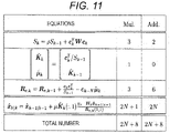
- Fig. 11 illustrates a table (Table 3) for describing the processing and time complexity of the C-whiten fast H ⁇ filterintroducing the relaxation factor ⁇ .
- Expression (56) of e ⁇ k and Expression (53) of e k have, in addition to original definitional expressions, theoretically-equivalent multiple expressions, and can be represented as described above. Moreover, in calculation of C-WFHF, the variables (with underscores) relating to backward prediction are not necessarily utilized, and therefore, calculation for these values is unnecessary.
- Fig. 12 illustrates a table (Table 4) for describing the processing and time complexity of the filter of C-NLMS algorithm.
- the fast H ⁇ filter can implement the following whitening in such a manner the linear prediction factor of the input signal is brought to zero.
- k x ⁇ k ⁇ 1
- K k-1 (1 :N-1,:) indicates a matrix including first to (N-1)-th rows of K k-1 .
- the regularization term 1 + ⁇ f -2 H k K k (:,1) of the denominator of the filter gain is one.
- the filter gain becomes too large and whitening becomes unstable (in the case of ⁇ f ⁇ ⁇ , the denominator includes H k K k (:,1), and therefore, a gain level is limited).
- the computational complexity of WFHF is O(3N).
- C-WFHF of the aspect of the present disclosure and/or the present embodiment is the technique of solving this problem and properly executing whitening.
- the linear prediction factors a k and b k are selectively set to zero from many parameters, for example.
- a proper expression is employed from many mathematical expressions of e ⁇ k , e k , e ⁇ kN , and e k .
- selection of a specific parameter as a specific value from many parameters and application of a specific expression of many expressions to the specific parameter are extremely sophisticated and difficult.
- whitening can be properly performed.
- optimization of a calculation expression in the case of considering implementation of C-WFHF and C-NLMS and estimation of a data processing amount have been performed by way of example. Optimization described herein specifically indicates "optimization for incorporation.” In this case, obtaining of an expression (a form) for minimizing the number of data processing of an incorporated program is, for example, called optimization.
- a "form maintaining a relationship with C-FHF” and a “form (an optimal version) suitable for incorporation" are theoretically equivalent to each other. For example, for the "form maintaining the relationship with C-FHF," the meaning of the algorithm thereof is easily understandable.
- the "form suitable for incorporation” is a form suitable for actual programing for the CPU.
- a necessary cycle number varies according to whether an incorporation target is multiplication (Mul.), division (Div.), or addition (Add.).
- Mul. multiplication
- Div. division
- Add. addition
- the cycle number is estimated from the number of times of data processing.
- the cycle number to be used greatly changes depending on, e.g., reading from a memory or a registry and data processing for parallelization.
- the cycle number was calculated without considering a change in the cycle number due to an incorporation method.
- Fig. 15 illustrates a table for describing the processing and time complexity of one example of the optimal version of the C-whiten fast H ⁇ filter.
- Expressions (60), (58), (55), (49), (50) of the C-whiten fast H ⁇ filter can be organized as follows.
- K ⁇ k-1 (1:N-1,1) described herein indicates a matrix of a first column from first to N-1-th rows of K ⁇ k-1 .
- C-WFHF C-whiten fast H ⁇ filter
- An optimization expression described herein is an expression recombined such that the number of times of data processing is decreased, and is theoretically equivalent to an expression before recombination.
- a N-th component is extracted and utilized from a first component of a first column of Expression (58) of C-WFHF, and in this manner, the following expression of K ⁇ k (:,1) is obtained.
- the computational complexity can be further reduced as compared to the previously-described C-whiten fast H ⁇ filter.
- Fig. 16 illustrates a table for describing the processing and time complexity of one example of the optimal version of the filter of the C-NLMS algorithm.
- Expressions (58), (55), (49), (50) of the filter of the C-NLMS algorithm can be organized as follows.
- the N-th component is, for example, extracted and utilized from the first component of the first column of Expression (58) of C-NLMS, and therefore, the following expression of K ⁇ k (:,1)is obtained.
- an example of the echo canceller will be described as the embodiment, and operation of the present identification algorithm will be checked.
- a communication echo canceller will be briefly described.
- An acoustic echo canceller essential for a recently-focused audio interface such as a smart speaker employs the same principle.
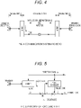
- Fig. 4 illustrates a diagram for describing a communication system and echo.
- a four-wire circuit is used because of a reason such as signal amplification.
- a subscriber line is for a relatively-short distance, and therefore, a two-wire circuit is used.
- a hybrid transformer is introduced as in Fig. 4 , and impedance matching is performed.
- impedance matching is complete, a signal (audio) from a speaker B reaches only a speaker A.
- Fig. 5 illustrates a principle diagram of the echo canceller.
- the echo canceller is introduced as in Fig. 5 .
- an impulse response of an echo path is sequentially estimated using the directly-observable received signal and echo.
- Pseudo echo obtained using such a result is subtracted from actual echo to cancel out the echo, and in this manner, the echo is removed.
- Estimation of the impulse response of the echo path is performed such that a mean square error of residual echo e k is minimized.
- elements interfering with estimation of the echo path include circuit noise and a signal (audio) from the speaker A.
- estimation of the impulse response is suspended.
- an observation value y k of echo d k is represented by the following expression by means of the impulse response hi[k] of the echo path, considering that the received signal u k is a signal input to the echo path.
- u k and y k each indicate the received signal andthe observation value of the echo at the time k
- v k is circuit noise with an average value of 0 at the time k.
- the tap number N is known.
- the cancelling problem can be reduced to the problem of how to sequentially estimate the impulse response hi[k] of the echo path from the directly-observable received signal u k and from the observation value y k of the directly-observable echo.
- Expression (65) is first expressed using the state space model including the equation of state and the equation of observation.
- x k + 1 x k + G k w k , x k , w k ⁇ R N
- y k H k x k + ⁇ k , y k , ⁇ k ⁇ R
- z k H k x k , z k ⁇ R , H k ⁇ R 1 ⁇ N
- Fig. 13 is a table (Table 5) of the impulse response of the echo path.
- u k ⁇ 1 u k ⁇ 1 + ⁇ 2 u k ⁇ 2 + w ′ k
- Figs. 6A and 6B illustrate graphs for describing transition of a tap square error in the present embodiment (C-FHF) and other methods.
- Figs. 6A and 6B illustrate results obtained from comparison of transition of a tap square error ⁇ x ⁇ k
- FHF fast H ⁇ filter
- FKF fast Kalman filter
- FTF fast transversal filter
- Fig. 7 illustrates a graph for describing an audio signal.
- Figs. 8A and 8B illustrate graphs for describing results when the audio signal of Fig. 7 is taken as input.
- the C-fast H ⁇ filter also exhibited better convergence performance and better tracking performance as compared to the fast Kalman filter and the fast transversal filter.
- K k can be organized as follows.
- the ex-post backward prediction error e k can be represented as follows by means of the ex-ante backward prediction error e ⁇ k .
- the ex-post forward prediction error e k can be represented as follows by means of the ex-ante forward prediction error e ⁇ k .
- the (N+1) ⁇ (N+1) matrix Q U k can be resolved into two ways as follows.
Landscapes
- Engineering & Computer Science (AREA)
- Signal Processing (AREA)
- Physics & Mathematics (AREA)
- Acoustics & Sound (AREA)
- Health & Medical Sciences (AREA)
- Computer Networks & Wireless Communication (AREA)
- Multimedia (AREA)
- Human Computer Interaction (AREA)
- Quality & Reliability (AREA)
- Computational Linguistics (AREA)
- Audiology, Speech & Language Pathology (AREA)
- Evolutionary Computation (AREA)
- Computer Hardware Design (AREA)
- Artificial Intelligence (AREA)
- Computer Vision & Pattern Recognition (AREA)
- Mathematical Physics (AREA)
- Medical Informatics (AREA)
- Software Systems (AREA)
- General Physics & Mathematics (AREA)
- Automation & Control Theory (AREA)
- Filters That Use Time-Delay Elements (AREA)
- Cable Transmission Systems, Equalization Of Radio And Reduction Of Echo (AREA)
- Debugging And Monitoring (AREA)
- Signal Processing For Digital Recording And Reproducing (AREA)
Claims (14)
- Systemidentifizierungsvorrichtung zum Durchführen einer schnellen Echtzeitidentifizierung für ein System aus Eingabe-/Ausgabedaten, umfassend:ein störungsunempfindliches Filter, das so konfiguriert ist, dass ein maximaler Energiegewinn aus der Störeinwirkung auf einen Filterfehler als Bewertungskriterium kleiner als ein vorgegebener oberer Grenzwert
 wobei das Filter durch die nachstehenden Ausdrücke (49), (50), (55), (58), (60) bis (62) einem Zustandsraummodell bereitgestellt wird, das durch die nachstehenden Ausdrücke (11) bis (13) dargestellt wird, um einen Schätzwert x^k|k eines Zustands xk des Systems zu erhalten:





 ck ∈ R2×1 ein erster Spaltenvektor von Ck = [ck,...,C k-N+1] ist,
 xk:ein Zustandsvektor oder lediglich ein Zustand; unbekannt ist und dies ein Ziel für die Schätzung ist,x0 als Anfangszustand definiert und unbekannt ist,wk als Systemrauschen definiert und unbekannt ist,vk als Beobachtungsrauschen definiert und unbekannt ist,yk als Beobachtungssignal definiert ist und als Filtereingabe genommen wird und bekannt ist,zk als Ausgabesignal definiert und unbekannt ist,Gk als Ansteuerungsmatrix definiert und bei der Ausführung bekannt ist,Hk als Beobachtungsmatrix definiert und bekannt ist,x^k|k als Schätzwert unter Verwendung von Beobachtungssignalen y0 bis yk des Zustands xk (eine Impulsantwort eines unbekannten Systems) zum Zeitpunkt k definiert ist und durch eine Filtergleichung bereitgestellt wird,x^-1|-1 als anfänglicher Schätzwert des Zustands definiert und in einer normalen Situation unbekannt ist, aber der Einfachheit halber null verwendet wird,K~ k als Filtergewinn definiert ist und rekursiv aus einer Matrix (58) mitK∼ -1=0 erhalten wird,Re,k als Hilfsvariable definiert ist und rekursiv aus der Formel (55) mit Re,-1 = R erhalten wird,N als Dimension (eine Abgriffnummer) des Zustandsvektors definiert ist und im Voraus bereitgestellt wird,µ~ k als N + 1-ter 1 × 2-Zeilenvektor von [ck/Sk-1, K∼T k-1]T definiert ist,W als Gewichtungsmatrix definiert ist und durch γf bestimmt wird,ek als nachträglicher Vorwärtsvorhersagefehler definiert und ein zweidimensionaler Spaltenvektor ist,ρ als Vergessensfaktor definiert ist,e~ k als Vorwärtsvorhersagefehler definiert und ein zweidimensionaler Spaltenvektor ist,Sk als Vorwärtsvorhersagefehlerleistung zum Zeitpunkt k definiert ist und rekursiv mit S-1 = 1/ε0 erhalten wird, wobei ε0 eine willkürliche positive Konstante ist,γf als Dämpfungspegel definiert ist und beim Entwerfen bereitgestellt wird undµ als Schrittgröße (ein Relaxationsfaktor) definiert und eine reelle Zahl von µ > 0 ist und im Voraus bereitgestellt wird.
 - Systemidentifizierungsvorrichtung nach Anspruch 1, wobei
für die Ausdrücke (58), (55), (49), (50) die folgenden Ausdrücke verwendet werden, die aus den Ausdrücken (58), (55), (49), (50) modifiziert wurden:


 wobei µ die Schrittweite und eine reelle Zahl von µ > 0 ist undx^k ein Schätzwert der Impulsantwort ist,x^k|k durch x^k in Übereinstimmung mit der adaptiven Filternotation ersetzt wird.
 - Systemidentifizierungsvorrichtung nach Anspruch 1, wobei
die folgenden Filterparameter festgelegt sind: yf = 1,0, ρ = 1,0, Sk = Sk-1 = S-1 = 1/ε0, sodass degenerierte Ausdrücke einschließlich der Ausdrücke (49), (50), (55), (58) für den Zustandsraummodus verwendet werden, der durch die Ausdrücke (11) bis (13) dargestellt wird, wobei die Ausdrücke (55) und (58) wie folgt definiert sind:

- Systemidentifizierungsvorrichtung nach Anspruch 1, wobei
für die Ausdrücke (58), (55), (49), (50) die folgenden Ausdrücke verwendet werden, die aus den Ausdrücken (58), (55), (49), (50) modifiziert wurden:

 wobei µ die Schrittweite und eine reelle Zahl von µ > 0 ist undx∧ k ein Schätzwert der Impulsantwort ist.
 - Systemidentifizierungsvorrichtung nach Anspruch 1 oder 2, ferner umfassend:einen Verarbeitungsabschnitt (101), der zum Ausführen des Filters konfiguriert ist,wobei der Verarbeitungsabschnitt (101) durchführteinen ersten Schritt des Lesens eines Anfangszustands eines rekursiven Ausdrucks aus einem Speicherabschnitt (105) oder des Empfangens des Anfangszustands von einem Eingabeabschnitt (102) oder einem Schnittstellenabschnitt (106), wodurch eine rekursive Variable des Filters initialisiert wird,einen zweiten Schritt des Ermittelns, ob die Zeit k eine voreingestellte Datenlänge L überschreitet, wodurch der Filtergewinn initialisiert und neu gestartet oder die Verarbeitung beendet wird, wenn die Zeit k die Datenlänge L überschreitet,einen dritten Schritt des Empfangens, wenn die Zeit k gleich der oder kleiner als die Datenlänge L ist, eines Eingabesignals uk von dem Eingabeabschnitt (102) oder dem Schnittstellenabschnitt (106) oder des Lesens des Eingabesignals uk aus dem Speicherabschnitt (105), wodurch eine erweiterte Beobachtungsmatrix Cu k mittels des Eingabesignals uk und einer Verschiebungskennlinie Cu k = [ck, ck-1]= [Ck, Ck-N] aktualisiert wird,einen vierten Schritt des Ausführens eines Filteralgorithmus pro Zeiteinheit, wobei der Filteralgorithmus eine Verarbeitung des Berechnens der Ausdrücke einschließt, um dem Filter einen zweiten Term auf einer rechten Seite des Ausdrucks (49) und den Relaxationsfaktor µ (µ ist eine reelle Zahl von µ > 0) in absteigender Reihenfolge von Ausdruck (62) bis Ausdruck (49) bereitzustellen,einen fünften Schritt des Aktualisierens einer Filtergleichung einschließlich des Ausdrucks (49) und des Speicherns des Zustandsschätzwerts x^k|k im Speicherabschnitt (105) und/oder des Ausgebens des Zustandsschätzwerts x^k|k aus einem Ausgabeabschnitt (103) oder aus dem Schnittstellenabschnitt (106) undeinen sechsten Schritt des Vorrückens der Zeit k und des Wiederholens der Verarbeitung des zweiten bis fünften Schritts.
- Systemidentifizierungsvorrichtung nach Anspruch 3 oder 4, ferner umfassend:einen Verarbeitungsabschnitt (101), der zum Ausführen des Filters konfiguriert ist,wobei der Verarbeitungsabschnitt (101) durchführteinen ersten Schritt des Lesens eines Anfangszustands eines rekursiven Ausdrucks aus einem Speicherabschnitt (105) oder des Empfangens des Anfangszustands von einem Eingabeabschnitt (102) oder einem Schnittstellenabschnitt (106), wodurch eine rekursive Variable des Filters initialisiert wird,einen zweiten Schritt des Ermittelns, ob die Zeit k eine voreingestellte Datenlänge L überschreitet, wodurch der Filtergewinn initialisiert und neu gestartet oder die Verarbeitung beendet wird, wenn die Zeit k die Datenlänge L überschreitet,einen dritten Schritt des Empfangens, wenn die Zeit k gleich der oder kleiner als die Datenlänge L ist, eines Eingabesignals uk von dem Eingabeabschnitt (102) oder dem Schnittstellenabschnitt (106) oder des Lesens des Eingabesignals uk aus dem Speicherabschnitt (105), wodurch eine erweiterte Beobachtungsmatrix Cu k mittels des Eingabesignals uk und einer Verschiebungskennlinie Cu k = [ck, Ck-1] = [Ck, ck-N] aktualisiert wird,einen vierten Schritt des Ausführens eines Filteralgorithmus pro Zeiteinheit, wobei der Filteralgorithmus eine Verarbeitung zum Berechnen der Ausdrücke einschließt, um dem Filter den Ausdruck (49) und die Schrittgröße µ (µ ist eine reelle Zahl von µ > 0) in absteigender Reihenfolge von Ausdruck (58) bis Ausdruck (49) bereitzustellen,einen fünften Schritt des Aktualisierens einer Filtergleichung einschließlich des Ausdrucks (49) und des Speicherns des Zustandsschätzwerts X^k|k im Speicherabschnitt (105) und/oder des Ausgebens des Zustandsschätzwerts X^k|k aus einem Ausgabeabschnitt (103) oder aus dem Schnittstellenabschnitt (106) undeinen sechsten Schritt des Vorrückens der Zeit k und des Wiederholens der Verarbeitung des zweiten bis fünften Schritts.
- Systemidentifizierungsvorrichtung nach einem der Ansprüche 1 bis 6, wobei
das Bewertungskriterium den nachstehenden Ausdruck (14) für das Zustandsraummodell erfüllt: wobei ef,i als Filterfehler definiert ist und ef,i = zv i|i - HiXi, zv i|i ein ausgegebener Schätzwert HiX^i|i ist,Σ0 -1 als inverse Matrix einer Gewichtungsmatrix definiert ist, die die Unsicherheit des Zustands darstellt, und Σ0 im Voraus angegeben wird.p als Vergessensfaktor definiert ist und wenn γf ermittelt wurde, typischerweise durch ρ = 1 - χ(γf) ermittelt wurde, auch unabhängig von γf ermittelt werden kann undγf als die Dämpfungspegel definiert ist und beim Entwerfen bereitgestellt wird.
 - Systemidentifizierungsvorrichtung nach Anspruch 5 oder 6, wobei
der Verarbeitungsabschnitt (101) des Filters im dritten Schritt einen Schritt zum Ermitteln einer skalaren Existenzbedingung eines nachstehenden Ausdrucks vor oder nach Ausführung der Verarbeitung ausführt und, wenn Ausdruck (30) nicht erfüllt ist, die Verarbeitung beendet oder neu startet:


- Systemidentifizierungsvorrichtung nach einem der Ansprüche 5, 6 und 8, wobei
der Verarbeitungsabschnitt (101) des Filters ferner im fünften Schritt einen Ausgabeschätzwert zv k|k, zv k|k-1 gemäß dem nachstehenden Ausdruck (48) berechnet, wodurch der Ausgabeschätzwert im Speicherabschnitt (105) gespeichert wird und/oder der Ausgabeschätzwert aus dem Ausgabeabschnitt (103) oder aus dem Schnittstellenabschnitt (106) ausgegeben wird: wobei z^k|k als Schätzwert Hkx^k|k unter Verwendung der Beobachtungssignale y0 bis yk der Ausgabe zk zum Zeitpunkt k definiert ist und durch die Filtergleichung bereitgestellt wird undz^k|k-1 als Einzelschritt-Vorhersagewert Hkx^k-1|k-1 unter Verwendung der Beobachtungssignale y0 bis yk-1 der Ausgabe zk zum Zeitpunkt k definiert ist und durch die Filtergleichung bereitgestellt wird.
 - Systemidentifizierungsvorrichtung nach einem der Ansprüche 1 bis 9, wobeidas Filter angewendet wird, um den Zustandsschätzwert x^k|k zu erhalten, undPseudo-Echo d^k wie in Ausdruck (66) unten geschätzt und vom Echo subtrahiert wird, um das Echo aufzuheben;

- Systemidentifizierungsverfahren zum Durchführen einer schnellen Echtzeitidentifizierung für ein System aus Eingabe-/Ausgabedaten, wobeiein störungsunempfindliches Filter so konfiguriert ist, dass ein maximaler Energiegewinn aus der Störeinwirkung auf einen Filterfehler als Bewertungskriterium kleiner als ein vorgegebener oberer Grenzwert γt2 unter der Bedingung festgelegt wird, dass angenommen wird, dass das Eingabesignal weißes Rauschen ist, unddas Filter durch die nachstehenden Ausdrücke (49), (50), (55), (58), (60) bis (62) einem Zustandsraummodell bereitgestellt wird, das durch die nachstehenden Ausdrücke (11) bis (13) dargestellt wird, um einen Schätzwert x^k|k eines Zustands xk des Systems zu erhalten:


 xk als Zustandsvektor oder lediglich als Zustand definiert und unbekannt ist und dies ein Ziel für die Schätzung ist,x0 als Anfangszustand definiert und unbekannt ist,wk als Systemrauschen definiert und unbekannt ist,vk als Beobachtungsrauschen definiert und unbekannt ist,yk als Beobachtungssignal definiert ist und als Filtereingabe genommen wird und bekannt ist,zk als Ausgabesignal definiert und unbekannt ist,Gk als Ansteuerungsmatrix definiert und bei der Ausführung bekannt ist,Hk als Beobachtungsmatrix definiert und bekannt ist,x^k|k als Schätzwert unter Verwendung von Beobachtungssignalen y0 bis yk des Zustands xk (eine Impulsantwort eines unbekannten Systems) zum Zeitpunkt k definiert ist und durch eine Filtergleichung bereitgestellt wird,x^-1|-1 als anfänglicher Schätzwert des Zustands definiert und in einer normalen Situation unbekannt ist, aber der Einfachheit halber null verwendet wird,K∼ k als Filtergewinn definiert ist und rekursiv aus einer Matrix (58) mit K~ -1 = 0 erhalten wird,Re,k als Hilfsvariable definiert ist und rekursiv aus der Formel (55) mit Re,-1 = R erhalten wird,N als Dimension (eine Abgriffnummer) des Zustandsvektors definiert ist und im Voraus bereitgestellt wird,µ∼ k als N + 1-ter 1 × 2-Zeilenvektor von [ck/Sk-1, K∼T k-1]T definiert ist,W als Gewichtungsmatrix definiert ist und durch γf bestimmt wird,ek als nachträglicher Vorwärtsvorhersagefehler definiert und ein zweidimensionaler Spaltenvektor ist,ρ als Vergessensfaktor definiert ist,e∼ k als Vorwärtsvorhersagefehler und zweidimensionaler Spaltenvektor definiert ist,Sk als Vorwärtsvorhersagefehlerleistung zum Zeitpunkt k definiert ist und rekursiv mit S-1 = 1/ε0 erhalten wird, wobei ε0 eine willkürliche positive Konstante ist,γf als Dämpfungspegel definiert ist und beim Entwerfen bereitgestellt wird undµ als Schrittgröße (ein Relaxationsfaktor) definiert und eine reelle Zahl von µ > 0 ist und im Voraus bereitgestellt wird.
 - Systemidentifizierungsprogramm nach Anspruch 11, wobei die folgenden Filterparameter festgelegt sind: γf = 1,0, ρ = 1,0, Sk = Sk-1 = S-1 = 1/ε0, sodass degenerierte Ausdrücke einschließlich der Ausdrücke (49), (50), (55), (58) für den Zustandsraummodus verwendet werden, der durch die Ausdrücke (11) bis (13) dargestellt wird, wobei die Ausdrücke (55) und (58) wie folgt definiert sind:


- Systemidentifizierungsprogramm, um einen Computer zu veranlassen, eine schnelle Echtzeitidentifizierung für ein System aus Eingabe-/Ausgabedaten auszuführen, wobei
der Computer ausführteinen Schritt des Bereitstellens, durch einen Verarbeitungsabschnitt (101), eines Filters für ein Zustandsraummodell, das durch die nachstehenden Ausdrücke (11) bis (13) dargestellt wird, gemäß den Ausdrücken (49), (50), (55), (58), (60) bis (62) unten,einen Schritt des Lesens, durch den Verarbeitungsabschnitt (101), eines Anfangszustands eines rekursiven Ausdrucks aus einem Speicherabschnitt (105) oder des Empfangens des Anfangszustands von einem Eingabeabschnitt (102) oder einem Schnittstellenabschnitt (106), wodurch eine rekursive Variable des Filters initialisiert wird,einen Schritt des Festlegens, durch den Verarbeitungsabschnitt (101), des Filters, sodass ein maximaler Energiegewinn aus einer Störeinwirkung auf einen Filterfehler als Bewertungskriterium kleiner als ein vorgegebener oberer Grenzwert einen Schritt des Speicherns, durch den Verarbeitungsabschnitt (101), des Zustandsschätzwerts x^k|k in dem Speicherabschnitt (105) und/oder des Ausgebens des Zustandsschätzwerts x^k|k aus einem Ausgabeabschnitt (103) oder aus dem Schnittstellenabschnitt (106):


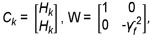
 wobei Ck und W durch die folgenden Ausdrücke definiert sind:
 ck ∈ R 2 × 1 ein erster Spaltenvektor von Ck = [ck,...,c k-N+1] ist,
 xk als Zustandsvektor oder lediglich als Zustand definiert ist, unbekannt ist und dies ein Ziel für die Schätzung ist,x0 als Anfangszustand definiert und unbekannt ist,wk als Systemrauschen definiert und unbekannt ist,vk als Beobachtungsrauschen definiert und unbekannt ist,yk als Beobachtungssignal definiert ist und als Filtereingabe genommen wird und bekannt ist,zk als Ausgabesignal definiert und unbekannt ist,Gk als Ansteuerungsmatrix definiert und bei der Ausführung bekannt ist,Hk als Beobachtungsmatrix definiert und bekannt ist,x^k|k als Schätzwert unter Verwendung von Beobachtungssignalen y0 bis yk des Zustands xk (eine Impulsantwort eines unbekannten Systems) zum Zeitpunkt k definiert ist und durch eine Filtergleichung bereitgestellt wird,x^-1|-1 als anfänglicher Schätzwert des Zustands definiert und in einer normalen Situation unbekannt ist, aber der Einfachheit halber null verwendet wird,K∼ k als Filtergewinn definiert ist und rekursiv aus einer Matrix (58) mit K~ -1 = 0 erhalten wird,Re,k als Hilfsvariable definiert ist und rekursiv aus der Formel (55) mit Re,-1 = R erhalten wird,N als Dimension (eine Abgriffnummer) des Zustandsvektors definiert ist und im Voraus bereitgestellt wird,µ∼ k als N + 1-ter 1 × 2-Zeilenvektor von [ck/Sk-1, K~T k-1]T definiert ist,W als Gewichtungsmatrix definiert ist und durch γf bestimmt wird,ek als nachträglicher Vorwärtsvorhersagefehler definiert und ein zweidimensionaler Spaltenvektor ist,ρ als Vergessensfaktor definiert ist,e∼ k als Vorwärtsvorhersagefehler und zweidimensionaler Spaltenvektor definiert ist,Sk als Vorwärtsvorhersagefehlerleistung zum Zeitpunkt k definiert ist und rekursiv mit S-1 = 1/ε0 erhalten wird, wobei ε0 eine willkürliche positive Konstante ist,γf als Dämpfungspegel definiert ist und beim Entwerfen bereitgestellt wird undµ als Schrittgröße (ein Relaxationsfaktor) definiert und eine reelle Zahl von µ > 0 ist und im Voraus bereitgestellt wird.
 - Systemidentifizierungsprogramm nach Anspruch 13, wobei die folgenden Filterparameter festgelegt sind: γf = 1,0, ρ = 1,0, Sk = Sk-1 = S-1 = 1/ε0, sodass degenerierte Ausdrücke einschließlich der Ausdrücke (49), (50), (55), (58) für den Zustandsraummodus verwendet werden, der durch die Ausdrücke (11) bis (13) dargestellt wird, wobei die Ausdrücke (55) und (58) wie folgt definiert sind:


Applications Claiming Priority (1)
| Application Number | Priority Date | Filing Date | Title |
|---|---|---|---|
| JP2018098503A JP6894402B2 (ja) | 2018-05-23 | 2018-05-23 | システム同定装置及び方法及びプログラム及び記憶媒体 |
Publications (3)
| Publication Number | Publication Date |
|---|---|
| EP3573233A2 EP3573233A2 (de) | 2019-11-27 |
| EP3573233A3 EP3573233A3 (de) | 2019-12-11 |
| EP3573233B1 true EP3573233B1 (de) | 2022-11-16 |
Family
ID=66826806
Family Applications (1)
| Application Number | Title | Priority Date | Filing Date |
|---|---|---|---|
| EP19176004.0A Active EP3573233B1 (de) | 2018-05-23 | 2019-05-22 | Systemidentifizierungsvorrichtung, systemidentifizierungsverfahren, systemidentifizierungsprogramm und aufzeichnungsmedium mit darauf aufgezeichnetem systemidentifizierungsprogramm |
Country Status (4)
| Country | Link |
|---|---|
| US (1) | US10863272B2 (de) |
| EP (1) | EP3573233B1 (de) |
| JP (1) | JP6894402B2 (de) |
| CN (1) | CN110535452B (de) |
Families Citing this family (4)
| Publication number | Priority date | Publication date | Assignee | Title |
|---|---|---|---|---|
| CN113691237B (zh) * | 2021-07-27 | 2024-01-02 | 浙江工商大学 | 一种加权融合鲁棒滤波方法 |
| CN115167320B (zh) * | 2022-08-09 | 2025-09-19 | 中控技术股份有限公司 | 工业控制系统的模型识别方法、装置、设备及存储介质 |
| CN116484197B (zh) * | 2023-04-27 | 2025-05-23 | 西安电子科技大学 | 噪声干扰下的fir滤波器系数识别方法及装置 |
| CN118970417B (zh) * | 2024-10-18 | 2025-03-18 | 西北电子设备研究所(中国电子科技集团公司第三十九研究所) | 大口径反射面天线风扰补偿控制方法、系统、设备及介质 |
Family Cites Families (10)
| Publication number | Priority date | Publication date | Assignee | Title |
|---|---|---|---|---|
| SE516835C2 (sv) * | 1995-02-15 | 2002-03-12 | Ericsson Telefon Ab L M | Ekosläckningsförfarande |
| JP3654470B2 (ja) * | 1996-09-13 | 2005-06-02 | 日本電信電話株式会社 | サブバンド多チャネル音声通信会議用反響消去方法 |
| JP4067269B2 (ja) | 2000-10-24 | 2008-03-26 | 独立行政法人科学技術振興機構 | システム同定方法 |
| CA2399159A1 (en) * | 2002-08-16 | 2004-02-16 | Dspfactory Ltd. | Convergence improvement for oversampled subband adaptive filters |
| US7480595B2 (en) | 2003-08-11 | 2009-01-20 | Japan Science And Technology Agency | System estimation method and program, recording medium, and system estimation device |
| JP5196653B2 (ja) | 2006-04-14 | 2013-05-15 | 国立大学法人岩手大学 | システム同定方法及びプログラム及び記憶媒体、システム同定装置 |
| NL2011975C2 (nl) * | 2013-12-17 | 2015-06-18 | Berkin Bv | Stromingsmeetapparaat van het thermische type. |
| US9729968B2 (en) * | 2014-03-05 | 2017-08-08 | Texas Instruments Incorporated | Method and system for acoustic echo cancellation using cascaded kalman filtering |
| US9881630B2 (en) * | 2015-12-30 | 2018-01-30 | Google Llc | Acoustic keystroke transient canceler for speech communication terminals using a semi-blind adaptive filter model |
| US10229698B1 (en) * | 2017-06-21 | 2019-03-12 | Amazon Technologies, Inc. | Playback reference signal-assisted multi-microphone interference canceler |
-
2018
- 2018-05-23 JP JP2018098503A patent/JP6894402B2/ja active Active
-
2019
- 2019-05-21 US US16/418,579 patent/US10863272B2/en active Active
- 2019-05-22 EP EP19176004.0A patent/EP3573233B1/de active Active
- 2019-05-22 CN CN201910428966.8A patent/CN110535452B/zh active Active
Also Published As
| Publication number | Publication date |
|---|---|
| EP3573233A2 (de) | 2019-11-27 |
| US10863272B2 (en) | 2020-12-08 |
| JP2019205049A (ja) | 2019-11-28 |
| US20190364361A1 (en) | 2019-11-28 |
| EP3573233A3 (de) | 2019-12-11 |
| JP6894402B2 (ja) | 2021-06-30 |
| CN110535452A (zh) | 2019-12-03 |
| CN110535452B (zh) | 2024-09-13 |
Similar Documents
| Publication | Publication Date | Title |
|---|---|---|
| EP3573233B1 (de) | Systemidentifizierungsvorrichtung, systemidentifizierungsverfahren, systemidentifizierungsprogramm und aufzeichnungsmedium mit darauf aufgezeichnetem systemidentifizierungsprogramm | |
| US8380466B2 (en) | System identification method and program, storage medium, and system identification device | |
| Gogineni et al. | Fractional-order correntropy filters for tracking dynamic systems in α-stable environments | |
| CN103229237A (zh) | 信号处理设备、信号处理方法以及信号处理程序 | |
| Lou et al. | Distributed incremental bias-compensated RLS estimation over multi-agent networks | |
| JP4444919B2 (ja) | システム推定方法及びプログラム及び記録媒体、システム推定装置 | |
| JP2002135171A (ja) | システム同定方法 | |
| Ishida et al. | Multikernel adaptive filters with multiple dictionaries and regularization | |
| Ahmad | A globally convergent stochastic pairwise conjugate gradient-based algorithm for adaptive filtering | |
| Dogariu et al. | Identification of Multilinear Forms with the Tensorial Kalman Filter | |
| Chen et al. | On the probability distribution of distributed optimization strategies | |
| Arezki et al. | A new algorithm with low complexity for adaptive filtering | |
| Meslem et al. | Set-valued state estimator with sparse and delayed measurements for uncertain discrete-time linear systems | |
| Pinheiro et al. | Newton-like nonlinear adaptive filters via simple multilinear functionals | |
| Nikolov et al. | Discrete adaptive real-time state observer development using least-squares method | |
| Wagner et al. | Comparisons of one and two adaptation gain complex ptnlms algorithms | |
| JP4344306B2 (ja) | 未知系推定方法およびこの方法を実施する装置 | |
| da Mata et al. | Maximum Likelihood Estimation of Dynamic Sub-Networks with Missing Data | |
| Rusu et al. | Cascaded RLS Adaptive Filters Based on a Kronecker Product Decomposition. Electronics 2022, 11, 409 | |
| Papo | Bias-variance tradeoff in a sliding window implementation of the stochastic gradient algorithm | |
| Xu | Condition and Methods to Suppress Zonotope Order Reduction Errors in Robust State Estimation Using Set‐Valued Observer | |
| Hatun et al. | Recursive successive over-relaxation algorithm for adaptive filtering | |
| Nishiyama | Algorithm understanding of the J-Fast H∞ filter based on linear prediction of input signal | |
| Andrews | Computational noise effects on adaptive filter algorithms | |
| Feng et al. | An adaptive algorithm for fast identification of IIR systems |
Legal Events
| Date | Code | Title | Description |
|---|---|---|---|
| PUAI | Public reference made under article 153(3) epc to a published international application that has entered the european phase |
Free format text: ORIGINAL CODE: 0009012 |
|
| STAA | Information on the status of an ep patent application or granted ep patent |
Free format text: STATUS: THE APPLICATION HAS BEEN PUBLISHED |
|
| PUAL | Search report despatched |
Free format text: ORIGINAL CODE: 0009013 |
|
| AK | Designated contracting states |
Kind code of ref document: A2 Designated state(s): AL AT BE BG CH CY CZ DE DK EE ES FI FR GB GR HR HU IE IS IT LI LT LU LV MC MK MT NL NO PL PT RO RS SE SI SK SM TR |
|
| AX | Request for extension of the european patent |
Extension state: BA ME |
|
| AK | Designated contracting states |
Kind code of ref document: A3 Designated state(s): AL AT BE BG CH CY CZ DE DK EE ES FI FR GB GR HR HU IE IS IT LI LT LU LV MC MK MT NL NO PL PT RO RS SE SI SK SM TR |
|
| AX | Request for extension of the european patent |
Extension state: BA ME |
|
| RIC1 | Information provided on ipc code assigned before grant |
Ipc: G05B 13/02 20060101ALN20191105BHEP Ipc: H03H 21/00 20060101AFI20191105BHEP Ipc: H04B 3/23 20060101ALN20191105BHEP |
|
| STAA | Information on the status of an ep patent application or granted ep patent |
Free format text: STATUS: REQUEST FOR EXAMINATION WAS MADE |
|
| 17P | Request for examination filed |
Effective date: 20200609 |
|
| RBV | Designated contracting states (corrected) |
Designated state(s): AL AT BE BG CH CY CZ DE DK EE ES FI FR GB GR HR HU IE IS IT LI LT LU LV MC MK MT NL NO PL PT RO RS SE SI SK SM TR |
|
| RIC1 | Information provided on ipc code assigned before grant |
Ipc: G05B 13/02 20060101ALN20210216BHEP Ipc: G05B 13/04 20060101ALN20210216BHEP Ipc: H04B 3/23 20060101ALN20210216BHEP Ipc: H03H 21/00 20060101AFI20210216BHEP |
|
| RIC1 | Information provided on ipc code assigned before grant |
Ipc: G05B 13/04 20060101ALN20210219BHEP Ipc: H04B 3/23 20060101ALN20210219BHEP Ipc: H03H 21/00 20060101AFI20210219BHEP Ipc: G05B 13/02 20060101ALN20210219BHEP |
|
| RIC1 | Information provided on ipc code assigned before grant |
Ipc: H03H 21/00 20060101AFI20210310BHEP Ipc: G05B 13/02 20060101ALN20210310BHEP Ipc: H04B 3/23 20060101ALN20210310BHEP Ipc: G05B 13/04 20060101ALN20210310BHEP |
|
| GRAP | Despatch of communication of intention to grant a patent |
Free format text: ORIGINAL CODE: EPIDOSNIGR1 |
|
| STAA | Information on the status of an ep patent application or granted ep patent |
Free format text: STATUS: GRANT OF PATENT IS INTENDED |
|
| INTG | Intention to grant announced |
Effective date: 20210504 |
|
| GRAJ | Information related to disapproval of communication of intention to grant by the applicant or resumption of examination proceedings by the epo deleted |
Free format text: ORIGINAL CODE: EPIDOSDIGR1 |
|
| STAA | Information on the status of an ep patent application or granted ep patent |
Free format text: STATUS: REQUEST FOR EXAMINATION WAS MADE |
|
| STAA | Information on the status of an ep patent application or granted ep patent |
Free format text: STATUS: EXAMINATION IS IN PROGRESS |
|
| INTC | Intention to grant announced (deleted) | ||
| 17Q | First examination report despatched |
Effective date: 20210922 |
|
| RAP3 | Party data changed (applicant data changed or rights of an application transferred) |
Owner name: RION CO., LTD. Owner name: NATIONAL UNIVERSITY CORPORATION, IWATE UNIVERSITY |
|
| RIC1 | Information provided on ipc code assigned before grant |
Ipc: G05B 13/04 20060101ALN20220516BHEP Ipc: H04B 3/23 20060101ALN20220516BHEP Ipc: G05B 13/02 20060101ALN20220516BHEP Ipc: H03H 21/00 20060101AFI20220516BHEP |
|
| GRAP | Despatch of communication of intention to grant a patent |
Free format text: ORIGINAL CODE: EPIDOSNIGR1 |
|
| STAA | Information on the status of an ep patent application or granted ep patent |
Free format text: STATUS: GRANT OF PATENT IS INTENDED |
|
| INTG | Intention to grant announced |
Effective date: 20220630 |
|
| GRAS | Grant fee paid |
Free format text: ORIGINAL CODE: EPIDOSNIGR3 |
|
| GRAA | (expected) grant |
Free format text: ORIGINAL CODE: 0009210 |
|
| STAA | Information on the status of an ep patent application or granted ep patent |
Free format text: STATUS: THE PATENT HAS BEEN GRANTED |
|
| AK | Designated contracting states |
Kind code of ref document: B1 Designated state(s): AL AT BE BG CH CY CZ DE DK EE ES FI FR GB GR HR HU IE IS IT LI LT LU LV MC MK MT NL NO PL PT RO RS SE SI SK SM TR |
|
| REG | Reference to a national code |
Ref country code: GB Ref legal event code: FG4D |
|
| REG | Reference to a national code |
Ref country code: CH Ref legal event code: EP |
|
| REG | Reference to a national code |
Ref country code: IE Ref legal event code: FG4D |
|
| REG | Reference to a national code |
Ref country code: DE Ref legal event code: R096 Ref document number: 602019021903 Country of ref document: DE |
|
| REG | Reference to a national code |
Ref country code: AT Ref legal event code: REF Ref document number: 1532387 Country of ref document: AT Kind code of ref document: T Effective date: 20221215 |
|
| REG | Reference to a national code |
Ref country code: DK Ref legal event code: T3 Effective date: 20221222 |
|
| REG | Reference to a national code |
Ref country code: LT Ref legal event code: MG9D |
|
| REG | Reference to a national code |
Ref country code: NL Ref legal event code: MP Effective date: 20221116 |
|
| REG | Reference to a national code |
Ref country code: AT Ref legal event code: MK05 Ref document number: 1532387 Country of ref document: AT Kind code of ref document: T Effective date: 20221116 |
|
| PG25 | Lapsed in a contracting state [announced via postgrant information from national office to epo] |
Ref country code: SE Free format text: LAPSE BECAUSE OF FAILURE TO SUBMIT A TRANSLATION OF THE DESCRIPTION OR TO PAY THE FEE WITHIN THE PRESCRIBED TIME-LIMIT Effective date: 20221116 Ref country code: PT Free format text: LAPSE BECAUSE OF FAILURE TO SUBMIT A TRANSLATION OF THE DESCRIPTION OR TO PAY THE FEE WITHIN THE PRESCRIBED TIME-LIMIT Effective date: 20230316 Ref country code: NO Free format text: LAPSE BECAUSE OF FAILURE TO SUBMIT A TRANSLATION OF THE DESCRIPTION OR TO PAY THE FEE WITHIN THE PRESCRIBED TIME-LIMIT Effective date: 20230216 Ref country code: LT Free format text: LAPSE BECAUSE OF FAILURE TO SUBMIT A TRANSLATION OF THE DESCRIPTION OR TO PAY THE FEE WITHIN THE PRESCRIBED TIME-LIMIT Effective date: 20221116 Ref country code: FI Free format text: LAPSE BECAUSE OF FAILURE TO SUBMIT A TRANSLATION OF THE DESCRIPTION OR TO PAY THE FEE WITHIN THE PRESCRIBED TIME-LIMIT Effective date: 20221116 Ref country code: ES Free format text: LAPSE BECAUSE OF FAILURE TO SUBMIT A TRANSLATION OF THE DESCRIPTION OR TO PAY THE FEE WITHIN THE PRESCRIBED TIME-LIMIT Effective date: 20221116 Ref country code: AT Free format text: LAPSE BECAUSE OF FAILURE TO SUBMIT A TRANSLATION OF THE DESCRIPTION OR TO PAY THE FEE WITHIN THE PRESCRIBED TIME-LIMIT Effective date: 20221116 |
|
| PG25 | Lapsed in a contracting state [announced via postgrant information from national office to epo] |
Ref country code: RS Free format text: LAPSE BECAUSE OF FAILURE TO SUBMIT A TRANSLATION OF THE DESCRIPTION OR TO PAY THE FEE WITHIN THE PRESCRIBED TIME-LIMIT Effective date: 20221116 Ref country code: PL Free format text: LAPSE BECAUSE OF FAILURE TO SUBMIT A TRANSLATION OF THE DESCRIPTION OR TO PAY THE FEE WITHIN THE PRESCRIBED TIME-LIMIT Effective date: 20221116 Ref country code: LV Free format text: LAPSE BECAUSE OF FAILURE TO SUBMIT A TRANSLATION OF THE DESCRIPTION OR TO PAY THE FEE WITHIN THE PRESCRIBED TIME-LIMIT Effective date: 20221116 Ref country code: IS Free format text: LAPSE BECAUSE OF FAILURE TO SUBMIT A TRANSLATION OF THE DESCRIPTION OR TO PAY THE FEE WITHIN THE PRESCRIBED TIME-LIMIT Effective date: 20230316 Ref country code: HR Free format text: LAPSE BECAUSE OF FAILURE TO SUBMIT A TRANSLATION OF THE DESCRIPTION OR TO PAY THE FEE WITHIN THE PRESCRIBED TIME-LIMIT Effective date: 20221116 Ref country code: GR Free format text: LAPSE BECAUSE OF FAILURE TO SUBMIT A TRANSLATION OF THE DESCRIPTION OR TO PAY THE FEE WITHIN THE PRESCRIBED TIME-LIMIT Effective date: 20230217 |
|
| PG25 | Lapsed in a contracting state [announced via postgrant information from national office to epo] |
Ref country code: NL Free format text: LAPSE BECAUSE OF FAILURE TO SUBMIT A TRANSLATION OF THE DESCRIPTION OR TO PAY THE FEE WITHIN THE PRESCRIBED TIME-LIMIT Effective date: 20221116 |
|
| PG25 | Lapsed in a contracting state [announced via postgrant information from national office to epo] |
Ref country code: SM Free format text: LAPSE BECAUSE OF FAILURE TO SUBMIT A TRANSLATION OF THE DESCRIPTION OR TO PAY THE FEE WITHIN THE PRESCRIBED TIME-LIMIT Effective date: 20221116 Ref country code: RO Free format text: LAPSE BECAUSE OF FAILURE TO SUBMIT A TRANSLATION OF THE DESCRIPTION OR TO PAY THE FEE WITHIN THE PRESCRIBED TIME-LIMIT Effective date: 20221116 Ref country code: EE Free format text: LAPSE BECAUSE OF FAILURE TO SUBMIT A TRANSLATION OF THE DESCRIPTION OR TO PAY THE FEE WITHIN THE PRESCRIBED TIME-LIMIT Effective date: 20221116 Ref country code: CZ Free format text: LAPSE BECAUSE OF FAILURE TO SUBMIT A TRANSLATION OF THE DESCRIPTION OR TO PAY THE FEE WITHIN THE PRESCRIBED TIME-LIMIT Effective date: 20221116 |
|
| P01 | Opt-out of the competence of the unified patent court (upc) registered |
Effective date: 20230628 |
|
| REG | Reference to a national code |
Ref country code: DE Ref legal event code: R097 Ref document number: 602019021903 Country of ref document: DE |
|
| PG25 | Lapsed in a contracting state [announced via postgrant information from national office to epo] |
Ref country code: SK Free format text: LAPSE BECAUSE OF FAILURE TO SUBMIT A TRANSLATION OF THE DESCRIPTION OR TO PAY THE FEE WITHIN THE PRESCRIBED TIME-LIMIT Effective date: 20221116 Ref country code: AL Free format text: LAPSE BECAUSE OF FAILURE TO SUBMIT A TRANSLATION OF THE DESCRIPTION OR TO PAY THE FEE WITHIN THE PRESCRIBED TIME-LIMIT Effective date: 20221116 |
|
| PLBE | No opposition filed within time limit |
Free format text: ORIGINAL CODE: 0009261 |
|
| STAA | Information on the status of an ep patent application or granted ep patent |
Free format text: STATUS: NO OPPOSITION FILED WITHIN TIME LIMIT |
|
| 26N | No opposition filed |
Effective date: 20230817 |
|
| PG25 | Lapsed in a contracting state [announced via postgrant information from national office to epo] |
Ref country code: SI Free format text: LAPSE BECAUSE OF FAILURE TO SUBMIT A TRANSLATION OF THE DESCRIPTION OR TO PAY THE FEE WITHIN THE PRESCRIBED TIME-LIMIT Effective date: 20221116 |
|
| PG25 | Lapsed in a contracting state [announced via postgrant information from national office to epo] |
Ref country code: MC Free format text: LAPSE BECAUSE OF FAILURE TO SUBMIT A TRANSLATION OF THE DESCRIPTION OR TO PAY THE FEE WITHIN THE PRESCRIBED TIME-LIMIT Effective date: 20221116 |
|
| GBPC | Gb: european patent ceased through non-payment of renewal fee |
Effective date: 20230522 |
|
| REG | Reference to a national code |
Ref country code: BE Ref legal event code: MM Effective date: 20230531 |
|
| PG25 | Lapsed in a contracting state [announced via postgrant information from national office to epo] |
Ref country code: MC Free format text: LAPSE BECAUSE OF FAILURE TO SUBMIT A TRANSLATION OF THE DESCRIPTION OR TO PAY THE FEE WITHIN THE PRESCRIBED TIME-LIMIT Effective date: 20221116 Ref country code: LU Free format text: LAPSE BECAUSE OF NON-PAYMENT OF DUE FEES Effective date: 20230522 |
|
| REG | Reference to a national code |
Ref country code: IE Ref legal event code: MM4A |
|
| PG25 | Lapsed in a contracting state [announced via postgrant information from national office to epo] |
Ref country code: IE Free format text: LAPSE BECAUSE OF NON-PAYMENT OF DUE FEES Effective date: 20230522 |
|
| PG25 | Lapsed in a contracting state [announced via postgrant information from national office to epo] |
Ref country code: IE Free format text: LAPSE BECAUSE OF NON-PAYMENT OF DUE FEES Effective date: 20230522 Ref country code: GB Free format text: LAPSE BECAUSE OF NON-PAYMENT OF DUE FEES Effective date: 20230522 |
|
| PG25 | Lapsed in a contracting state [announced via postgrant information from national office to epo] |
Ref country code: IT Free format text: LAPSE BECAUSE OF FAILURE TO SUBMIT A TRANSLATION OF THE DESCRIPTION OR TO PAY THE FEE WITHIN THE PRESCRIBED TIME-LIMIT Effective date: 20221116 Ref country code: FR Free format text: LAPSE BECAUSE OF NON-PAYMENT OF DUE FEES Effective date: 20230531 Ref country code: BE Free format text: LAPSE BECAUSE OF NON-PAYMENT OF DUE FEES Effective date: 20230531 |
|
| PG25 | Lapsed in a contracting state [announced via postgrant information from national office to epo] |
Ref country code: BG Free format text: LAPSE BECAUSE OF FAILURE TO SUBMIT A TRANSLATION OF THE DESCRIPTION OR TO PAY THE FEE WITHIN THE PRESCRIBED TIME-LIMIT Effective date: 20221116 |
|
| PG25 | Lapsed in a contracting state [announced via postgrant information from national office to epo] |
Ref country code: BG Free format text: LAPSE BECAUSE OF FAILURE TO SUBMIT A TRANSLATION OF THE DESCRIPTION OR TO PAY THE FEE WITHIN THE PRESCRIBED TIME-LIMIT Effective date: 20221116 |
|
| PGFP | Annual fee paid to national office [announced via postgrant information from national office to epo] |
Ref country code: DE Payment date: 20250521 Year of fee payment: 7 |
|
| PGFP | Annual fee paid to national office [announced via postgrant information from national office to epo] |
Ref country code: DK Payment date: 20250526 Year of fee payment: 7 |
|
| PGFP | Annual fee paid to national office [announced via postgrant information from national office to epo] |
Ref country code: CH Payment date: 20250601 Year of fee payment: 7 |
|
| PG25 | Lapsed in a contracting state [announced via postgrant information from national office to epo] |
Ref country code: CY Free format text: LAPSE BECAUSE OF FAILURE TO SUBMIT A TRANSLATION OF THE DESCRIPTION OR TO PAY THE FEE WITHIN THE PRESCRIBED TIME-LIMIT; INVALID AB INITIO Effective date: 20190522 |
|
| PG25 | Lapsed in a contracting state [announced via postgrant information from national office to epo] |
Ref country code: HU Free format text: LAPSE BECAUSE OF FAILURE TO SUBMIT A TRANSLATION OF THE DESCRIPTION OR TO PAY THE FEE WITHIN THE PRESCRIBED TIME-LIMIT; INVALID AB INITIO Effective date: 20190522 |
|
| PG25 | Lapsed in a contracting state [announced via postgrant information from national office to epo] |
Ref country code: TR Free format text: LAPSE BECAUSE OF FAILURE TO SUBMIT A TRANSLATION OF THE DESCRIPTION OR TO PAY THE FEE WITHIN THE PRESCRIBED TIME-LIMIT Effective date: 20221116 |