EP3573228B1 - Electric rotor dynamics damping - Google Patents
Electric rotor dynamics damping Download PDFInfo
- Publication number
- EP3573228B1 EP3573228B1 EP19176316.8A EP19176316A EP3573228B1 EP 3573228 B1 EP3573228 B1 EP 3573228B1 EP 19176316 A EP19176316 A EP 19176316A EP 3573228 B1 EP3573228 B1 EP 3573228B1
- Authority
- EP
- European Patent Office
- Prior art keywords
- rotor system
- rotor
- electric motor
- shaft
- generator
- Prior art date
- Legal status (The legal status is an assumption and is not a legal conclusion. Google has not performed a legal analysis and makes no representation as to the accuracy of the status listed.)
- Active
Links
Images

Classifications
-
- F—MECHANICAL ENGINEERING; LIGHTING; HEATING; WEAPONS; BLASTING
- F01—MACHINES OR ENGINES IN GENERAL; ENGINE PLANTS IN GENERAL; STEAM ENGINES
- F01D—NON-POSITIVE DISPLACEMENT MACHINES OR ENGINES, e.g. STEAM TURBINES
- F01D15/00—Adaptations of machines or engines for special use; Combinations of engines with devices driven thereby
- F01D15/10—Adaptations for driving, or combinations with, electric generators
-
- F—MECHANICAL ENGINEERING; LIGHTING; HEATING; WEAPONS; BLASTING
- F03—MACHINES OR ENGINES FOR LIQUIDS; WIND, SPRING, OR WEIGHT MOTORS; PRODUCING MECHANICAL POWER OR A REACTIVE PROPULSIVE THRUST, NOT OTHERWISE PROVIDED FOR
- F03D—WIND MOTORS
- F03D7/00—Controlling wind motors
- F03D7/02—Controlling wind motors the wind motors having rotation axis substantially parallel to the air flow entering the rotor
- F03D7/0296—Controlling wind motors the wind motors having rotation axis substantially parallel to the air flow entering the rotor to prevent, counteract or reduce noise emissions
-
- F—MECHANICAL ENGINEERING; LIGHTING; HEATING; WEAPONS; BLASTING
- F02—COMBUSTION ENGINES; HOT-GAS OR COMBUSTION-PRODUCT ENGINE PLANTS
- F02C—GAS-TURBINE PLANTS; AIR INTAKES FOR JET-PROPULSION PLANTS; CONTROLLING FUEL SUPPLY IN AIR-BREATHING JET-PROPULSION PLANTS
- F02C7/00—Features, components parts, details or accessories, not provided for in, or of interest apart form groups F02C1/00 - F02C6/00; Air intakes for jet-propulsion plants
- F02C7/26—Starting; Ignition
- F02C7/268—Starting drives for the rotor, acting directly on the rotor of the gas turbine to be started
-
- F—MECHANICAL ENGINEERING; LIGHTING; HEATING; WEAPONS; BLASTING
- F03—MACHINES OR ENGINES FOR LIQUIDS; WIND, SPRING, OR WEIGHT MOTORS; PRODUCING MECHANICAL POWER OR A REACTIVE PROPULSIVE THRUST, NOT OTHERWISE PROVIDED FOR
- F03D—WIND MOTORS
- F03D17/00—Monitoring or testing of wind motors, e.g. diagnostics
-
- F—MECHANICAL ENGINEERING; LIGHTING; HEATING; WEAPONS; BLASTING
- F03—MACHINES OR ENGINES FOR LIQUIDS; WIND, SPRING, OR WEIGHT MOTORS; PRODUCING MECHANICAL POWER OR A REACTIVE PROPULSIVE THRUST, NOT OTHERWISE PROVIDED FOR
- F03D—WIND MOTORS
- F03D7/00—Controlling wind motors
- F03D7/02—Controlling wind motors the wind motors having rotation axis substantially parallel to the air flow entering the rotor
- F03D7/04—Automatic control; Regulation
- F03D7/042—Automatic control; Regulation by means of an electrical or electronic controller
- F03D7/043—Automatic control; Regulation by means of an electrical or electronic controller characterised by the type of control logic
- F03D7/045—Automatic control; Regulation by means of an electrical or electronic controller characterised by the type of control logic with model-based controls
-
- H—ELECTRICITY
- H02—GENERATION; CONVERSION OR DISTRIBUTION OF ELECTRIC POWER
- H02P—CONTROL OR REGULATION OF ELECTRIC MOTORS, ELECTRIC GENERATORS OR DYNAMO-ELECTRIC CONVERTERS; CONTROLLING TRANSFORMERS, REACTORS OR CHOKE COILS
- H02P9/00—Arrangements for controlling electric generators for the purpose of obtaining a desired output
- H02P9/10—Control effected upon generator excitation circuit to reduce harmful effects of overloads or transients, e.g. sudden application of load, sudden removal of load, sudden change of load
- H02P9/105—Control effected upon generator excitation circuit to reduce harmful effects of overloads or transients, e.g. sudden application of load, sudden removal of load, sudden change of load for increasing the stability
-
- F—MECHANICAL ENGINEERING; LIGHTING; HEATING; WEAPONS; BLASTING
- F05—INDEXING SCHEMES RELATING TO ENGINES OR PUMPS IN VARIOUS SUBCLASSES OF CLASSES F01-F04
- F05B—INDEXING SCHEME RELATING TO WIND, SPRING, WEIGHT, INERTIA OR LIKE MOTORS, TO MACHINES OR ENGINES FOR LIQUIDS COVERED BY SUBCLASSES F03B, F03D AND F03G
- F05B2260/00—Function
- F05B2260/96—Preventing, counteracting or reducing vibration or noise
-
- F—MECHANICAL ENGINEERING; LIGHTING; HEATING; WEAPONS; BLASTING
- F05—INDEXING SCHEMES RELATING TO ENGINES OR PUMPS IN VARIOUS SUBCLASSES OF CLASSES F01-F04
- F05B—INDEXING SCHEME RELATING TO WIND, SPRING, WEIGHT, INERTIA OR LIKE MOTORS, TO MACHINES OR ENGINES FOR LIQUIDS COVERED BY SUBCLASSES F03B, F03D AND F03G
- F05B2270/00—Control
- F05B2270/30—Control parameters, e.g. input parameters
- F05B2270/331—Mechanical loads
-
- F—MECHANICAL ENGINEERING; LIGHTING; HEATING; WEAPONS; BLASTING
- F05—INDEXING SCHEMES RELATING TO ENGINES OR PUMPS IN VARIOUS SUBCLASSES OF CLASSES F01-F04
- F05D—INDEXING SCHEME FOR ASPECTS RELATING TO NON-POSITIVE-DISPLACEMENT MACHINES OR ENGINES, GAS-TURBINES OR JET-PROPULSION PLANTS
- F05D2260/00—Function
- F05D2260/96—Preventing, counteracting or reducing vibration or noise
-
- F—MECHANICAL ENGINEERING; LIGHTING; HEATING; WEAPONS; BLASTING
- F05—INDEXING SCHEMES RELATING TO ENGINES OR PUMPS IN VARIOUS SUBCLASSES OF CLASSES F01-F04
- F05D—INDEXING SCHEME FOR ASPECTS RELATING TO NON-POSITIVE-DISPLACEMENT MACHINES OR ENGINES, GAS-TURBINES OR JET-PROPULSION PLANTS
- F05D2270/00—Control
- F05D2270/01—Purpose of the control system
- F05D2270/05—Purpose of the control system to affect the output of the engine
- F05D2270/052—Torque
-
- Y—GENERAL TAGGING OF NEW TECHNOLOGICAL DEVELOPMENTS; GENERAL TAGGING OF CROSS-SECTIONAL TECHNOLOGIES SPANNING OVER SEVERAL SECTIONS OF THE IPC; TECHNICAL SUBJECTS COVERED BY FORMER USPC CROSS-REFERENCE ART COLLECTIONS [XRACs] AND DIGESTS
- Y02—TECHNOLOGIES OR APPLICATIONS FOR MITIGATION OR ADAPTATION AGAINST CLIMATE CHANGE
- Y02E—REDUCTION OF GREENHOUSE GAS [GHG] EMISSIONS, RELATED TO ENERGY GENERATION, TRANSMISSION OR DISTRIBUTION
- Y02E10/00—Energy generation through renewable energy sources
- Y02E10/70—Wind energy
- Y02E10/72—Wind turbines with rotation axis in wind direction
Definitions
- the subject matter disclosed herein generally relates to rotating machinery and, more particularly, to a method and an apparatus for electric rotor dynamics damping.
- Rotor dynamics refer to motions and forces generated by high speed rotating machinery as a result of rotor rotation. These generally unwanted vibrations and motions can induce stress, drive vibration into the structure supporting the machinery or engine, and may result in rubbing between the rotating and static structure.
- rotor dynamics are accounted for during a machine design process by a combination of geometrical design of the rotor and static structures, and sets of springs and dampers, usually placed near or integral to bearing mounts.
- vibration modes can still result at certain operating speeds that excite rotor dynamic motions in rotating machinery.
- EP 2154780 A1 discloses an electrical power arrangement wherein torque vibration from a first electrical machine may be determined and then balanced by utilizing a second electrical machine to introduce an anti-phase torque vibration.
- WO 2016/098266 A1 discloses a gas turbine power generation system having a power oscillation damping control system for improved electric power stability.
- US 2006/244425 A1 discloses a method and damping device for damping a torsional oscillation in a rotating drive train.
- a rotor dynamics adjustment system as claimed in claim 1.
- damping correction torque includes a phase, a magnitude, and a sign of one or more torques to diminish the dynamic motion of the rotor system.
- further embodiments may include where the rotor system is a spool of a gas turbine engine.
- further embodiments may include where the electric motor is directly coupled to the shaft.
- further embodiments may include wherein the electric motor is coupled to the shaft through a geared interface.
- further embodiments may include where the electric motor-generator operable as a starter motor and as a generator to produce electric power.
- further embodiments may include where the rotor system is a low speed spool, and further including a high speed spool having a high pressure compressor, a high pressure turbine, and a second shaft concentrically arranged with respect to the shaft of the low speed spool.
- further embodiments may include a second electric motor operably coupled to the second shaft, where the electric motor and the second electric motor are independently controlled to each supply a supplemental motive force and fuel combustion in the combustor section provides a primary motive force for the low speed spool and the high speed spool.
- further embodiments may include where the rotor system includes at least one compressor section and at least one turbine section operably coupled to a shaft, and the electric motor is directly coupled to the shaft.
- further embodiments may include where the rotor system includes at least one compressor section and at least one turbine section operably coupled to a shaft, and the electric motor is coupled to the shaft through a geared interface.
- a technical effect of the apparatus, systems and methods is achieved by using dynamic torque and power capability of an electric motor operably coupled to a shaft of a rotating machine to damp out or excite rotor dynamic motions as described herein.
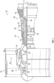
- FIG. 1 schematically illustrates a gas turbine engine 20.
- the gas turbine engine 20 is disclosed herein as a two-spool turbofan that generally incorporates a fan section 22, a compressor section 24, a combustor section 26 and a turbine section 28.
- the fan section 22 drives air along a bypass flow path B in a bypass duct, while the compressor section 24 drives air along a core flow path C for compression and communication into the combustor section 26 then expansion through the turbine section 28.
- FIG. 1 schematically illustrates a gas turbine engine 20.
- the gas turbine engine 20 is disclosed herein as a two-spool turbofan that generally incorporates a fan section 22, a compressor section 24, a combustor section 26 and a turbine section 28.
- the fan section 22 drives air along a bypass flow path B in a bypass duct
- the compressor section 24 drives air along a core flow path C for compression and communication into the combustor section 26 then expansion through the turbine section 28.
- the exemplary engine 20 generally includes a low speed spool 30 and a high speed spool 32 mounted for rotation about an engine central longitudinal axis A relative to an engine static structure 36 via several bearing systems 38. It should be understood that various bearing systems 38 at various locations may alternatively or additionally be provided, and the location of bearing systems 38 may be varied as appropriate to the application.
- the low speed spool 30 generally includes an inner shaft 40 that interconnects a fan 42, a low pressure compressor 44 and a low pressure turbine 46.
- the inner shaft 40 is connected to the fan 42 through a speed change mechanism, which in exemplary gas turbine engine 20 is illustrated as a geared architecture 48 to drive the fan 42 at a lower speed than the low speed spool 30.
- the high speed spool 32 includes an outer shaft 50 that interconnects a high pressure compressor 52 and high pressure turbine 54.
- a combustor 56 is arranged in exemplary gas turbine 20 between the high pressure compressor 52 and the high pressure turbine 54.
- An engine static structure 36 is arranged generally between the high pressure turbine 54 and the low pressure turbine 46.
- the engine static structure 36 further supports bearing systems 38 in the turbine section 28.
- the inner shaft 40 and the outer shaft 50 are concentric and rotate via bearing systems 38 about the engine central longitudinal axis A which is collinear with their longitudinal axes.
- each of the positions of the fan section 22, compressor section 24, combustor section 26, turbine section 28, and fan drive gear system 48 may be varied.
- gear system 48 may be located aft of combustor section 26 or even aft of turbine section 28, and fan section 22 may be positioned forward or aft of the location of gear system 48.
- the engine 20 in one example is a high-bypass geared aircraft engine.
- the engine 20 bypass ratio is greater than about six (6), with an example embodiment being greater than about ten (10)
- the geared architecture 48 is an epicyclic gear train, such as a planetary gear system or other gear system, with a gear reduction ratio of greater than about 2.3 and the low pressure turbine 46 has a pressure ratio that is greater than about five.
- the engine 20 bypass ratio is greater than about ten (10:1)
- the fan diameter is significantly larger than that of the low pressure compressor 44
- the low pressure turbine 46 has a pressure ratio that is greater than about five (5:1).
- Low pressure turbine 46 pressure ratio is pressure measured prior to inlet of low pressure turbine 46 as related to the pressure at the outlet of the low pressure turbine 46 prior to an exhaust nozzle.
- the geared architecture 48 may be an epicyclic gear train, such as a planetary gear system or other gear system, with a gear reduction ratio of greater than about 2.3:1. It should be understood, however, that the above parameters are only exemplary of one embodiment of a geared architecture engine and that the present disclosure is applicable to other gas turbine engines including direct drive turbofans.
- the fan section 22 of the engine 20 is designed for a particular flight condition--typically cruise at about 0.8 Mach and about 35,000 feet (10,688 meters).
- 'TSFC' Thrust Specific Fuel Consumption
- Low fan pressure ratio is the pressure ratio across the fan blade alone, without a Fan Exit Guide Vane (“FEGV”) system.
- the low fan pressure ratio as disclosed herein according to one non-limiting embodiment is less than about 1.45.
- Low corrected fan tip speed is the actual fan tip speed in ft/sec divided by an industry standard temperature correction of [(Tram °R)/(518.7 °R)] 0.5 .
- the "Low corrected fan tip speed” as disclosed herein according to one non-limiting embodiment is less than about 1150 ft/second (350.5 m/sec).
- FIG. 1 illustrates one example of the gas turbine engine 20
- any number of spools, inclusion or omission of the gear system 48, and/or other elements and subsystems are contemplated.
- rotor systems described herein can be used in a variety of applications and need not be limited to gas turbine engines for aircraft applications.
- rotor systems can be included in power generation systems, which may be ground-based as a fixed position or mobile system, and other such applications.
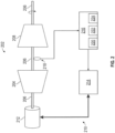
- FIG. 2 illustrates a rotor system 202 that includes at least one compressor section 204 and at least one turbine section 208 operably coupled to a shaft 206.
- the rotor system 202 can be a spool of the gas turbine engine 20 of FIG. 1 , such as the low speed spool 30 or the high speed spool 32.
- the at least one compressor section 204 can be equivalent to the low pressure compressor 44
- the shaft 206 can be equivalent to the inner shaft 40
- the at least one turbine section 208 can be equivalent to the low pressure turbine 46 of FIG. 1 .
- the at least one compressor section 204 can be equivalent to the high pressure compressor 52
- the shaft 206 can be equivalent to the outer shaft 50
- the at least one turbine section 208 can be equivalent to the high pressure turbine 54 of FIG. 1 .
- a rotor dynamics adjustment system 210 is operably coupled to the rotor system 202.
- the rotor dynamics adjustment system 210 includes an electric motor 212 directly coupled to the shaft 206.
- the rotor dynamics adjustment system 210 also includes drive electronics 214 operable to control current to the electric motor 212 to adjust the speed and/or torque of the electric motor 212.
- the electric motor 212 can be a direct current (DC) motor or an alternating current (AC) motor including conventional motor components, such as a motor rotor and motor stator, including a plurality of motor windings and/or permanent magnets.
- the drive electronics 214 can also include conventional motor current control electronics, such as filters, switching components, rectifiers, inverters, and the like.
- the electric motor 212 is a motor-generator operable in a generator mode to increase a load on the rotor system 202 and in a motoring mode to decrease the load of the rotor system 202.
- the drive electronics 214 may include power regulating circuitry and/or power converters to regulate electric power produced by the electric motor 212 in generator mode.
- the electric motor 212 can act as a variable frequency generator in generator mode due to speed fluctuations of rotation of the shaft 206, which may be primarily driven by the at least one turbine section 208.
- the electric motor 212 may be operable as a starter motor to partially or completely power rotation of the shaft 206 in a starting mode of operation (e.g., to start the gas turbine engine 20 of FIG. 1 ).
- Other uses and functions for the electric motor 212 are contemplated.
- a controller 216 of the rotor dynamics adjustment system 210 can monitor one or more rotor system sensors 218 while the rotor system 202 is rotating.
- the rotor system sensors 218 can be any type or combination of sensors operable to measure aspects of the motion of the rotor system 202.
- the rotor system sensors 218 can include one or more accelerometers, speed sensors, torque sensors, and the like.
- the controller 216 can control a speed and torque of the electric motor 212 through the drive electronics 214.
- the controller 216 may also control other system aspects, such as controlling operation of the gas turbine engine 20 of FIG. 1 .
- the controller 216 can include a processing system 220, a memory system 222, and an input/output interface 224.
- the processing system 220 can include any type or combination of central processing unit (CPU), including one or more of: a microprocessor, a digital signal processor (DSP), a microcontroller, an application specific integrated circuit (ASIC), a field programmable gate array (FPGA), or the like.
- the memory system 222 can store data and instructions that are executed by the processing system 220.
- the memory system 222 may include random access memory (RAM), read only memory (ROM), or other electronic, optical, magnetic, or any other computer readable medium onto which is stored data and algorithms in a non-transitory form.
- the input/output interface 224 is configured to collect sensor data from the one or more rotor system sensors 218 and interface with the drive electronics 214 and/or other systems (not depicted).
- the controller 216 is operable to characterize a dynamic motion of the rotor system 202 based on the sensor data from the one or more rotor system sensors 218. For example, the controller 216 may monitor a rotational speed of the shaft 206 and a vibrational amplitude and phase of the rotor system 202. The controller 216 can also monitor one or more torques on the shaft 206, for example, through direct torque measurements from the one or more rotor system sensors 218 or derived torques based on system models and/or known relationships based on mass, acceleration, and/or geometric configuration of the rotor system 202.
- the controller 216 is configured to determine a damping correction torque to diminish the dynamic motion of the rotor system 202 and command the electric motor 212 to apply the damping correction torque to the rotor system 202.
- the damping correction torque can include a phase, a magnitude, and a sign of one or more torques to diminish the dynamic motion of the rotor system 202.
- the controller 216 is configured to drive the electric motor 212 to apply one or more torque perturbations to a steady state load of the rotor system 202 to modify the dynamic motion of the rotor system 202. Further, the controller 216 is configured to operate the electric motor 212 in a generator mode to increase a load on the rotor system 202 and in a motoring mode to decrease the load of the rotor system 202. By damping out or exciting rotor dynamic motions through the electric motor 212, the dynamic motions of the rotor system 202 can be controlled.
- rotor system 202 The general form of the mathematical representation of these rotor systems, such as rotor system 202, can be derived from the geometry of the respective system and is well understood.
- rotor systems refer to the rotor and all of the static structure which contributes to the relevant dynamics of an engine. From these representations, robust control laws for a controller can be formatted using standard procedures. One such procedure is to excite the rotor system 202, for example with the motor 212 and controller 216, and measure the rotor response. The excitation can take several forms, such as: sinusoidal frequency and amplitude sweeps, ramps, stochastic disturbances, and others as is well known.
- the data so generated can then be used to identify the relevant dynamics of the engine geometry, most conveniently as separate vibrational modes often described in the form of eigenvectors and eigenvalues. Given this information, many standard mathematical techniques can be employed to formulate both linear and non-linear control laws. Note that this procedure need not be carried out on each engine unit, but may be more capable if done so depending on the geometrical uniformity of the manufacturing and assemble process.
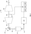
- FIG. 3 a schematic diagram of the rotor system 202 with a rotor dynamics adjustment system 310 is depicted as an alternate embodiment of the rotor dynamics adjustment system 210 of FIG. 2 .
- the controller 216 is operable to measure motion of the rotor system 202 through one or more rotor system sensors 218 and command the drive electronics 214 to modify a speed and/or torque of the electric motor 212 to apply a damping correction torque to the rotor system 202.
- the 3 includes a geared interface 301 that operably couples the electric motor 212 to the shaft 206.
- the geared interface 301 can include, for instance, a motor gear 303 coupled to a motor shaft 305 driven by the electric motor 212.
- the geared interface 301 can also include a rotor gear 307 coupled to the shaft 206.
- the motor gear 303 and the rotor gear 307 can each be beveled gears.
- the motor shaft 305 can be a tower shaft that enables the electric motor 212 to be separated at a greater distance from the rotor system 202 than in the rotor dynamics adjustment system 210 of FIG. 2 .
- Damping correction torque computations by the controller 216 can be adjusted to compensate for effects of the geared interface 301, such as gear backlash between the motor gear 303 and the rotor gear 307.
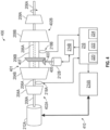
- FIG. 4 is a schematic diagram of a dual rotor system 400 with dynamic motion damping according to an embodiment.
- the dual rotor system 400 includes a first rotor system 402A and a second rotor system 402B, which may be an embodiment of the gas turbine engine 20 of FIG. 1 .
- the first rotor system 402A can be the low speed spool 30 of the gas turbine engine 20
- the second rotor system 402B can be the high speed spool 32 of the gas turbine engine 20.
- the first rotor system 402A can include a first compressor section 204A and a first turbine section 208A operably coupled to a first shaft 206A.
- the second rotor system 402B can include a second compressor section 204B and a second turbine section 208B operably coupled to a second shaft 206B, where the second shaft 206B is concentrically arranged with respect to the first shaft 206A.
- the first compressor section 204A can be equivalent to the low pressure compressor 44
- the first shaft 206A can be equivalent to the inner shaft 40
- the first turbine section 208A can be equivalent to the low pressure turbine 46 of FIG. 1
- the second compressor section 204B can be equivalent to the high pressure compressor 52
- the second shaft 206B can be equivalent to the outer shaft 50
- the second turbine section 208B can be equivalent to the high pressure turbine 54 of FIG. 1 .
- a rotor dynamics adjustment system 410 includes a first electric motor 212A driven by first drive electronics 214A and a second electric motor 212B driven by second drive electronics 214B.
- a first set of one or more rotor system sensors 218A may be associated with the first rotor system 402A, and a second set of one or more rotor system sensors 218B may be associated with the second rotor system 402B.
- a single instance of the controller 216 can be configured to independently control the first electric motor 212A responsive to sensor data from the first set of one or more rotor system sensors 218A, and separately control the second electric motor 212B responsive to sensor data from the second set of one or more rotor system sensors 218B.
- the controller 216 is further subdivided as two or more separate controls, for instance, where a separate instance of the controller 216 is provided for each of the first rotor system 402A and the second rotor system 402B.
- the first electric motor 212A and the second electric motor 212B can be independently controlled to each supply a supplemental motive force to the respective shafts 206A, 206B, where fuel combustion in the combustor section 26 ( FIG. 1 ) can provide a primary motive force for the first rotor system 402A as the low speed spool 30 and for the second rotor system 402B as the high speed spool 32.
- the first electric motor 212A is operably coupled to the first shaft 206A using a direct coupling
- the second electric motor 212B is operably coupled to the second shaft 206B using a geared interface 401.
- the geared interface 401 can include, for instance, a motor gear 403 coupled to a motor shaft 405 driven by the second electric motor 212B and a rotor gear 407 coupled to the second shaft 206B. While the example of FIG.
- first and second electric motors 212A, 212B depict the rotor dynamics adjustment system 410 with the first and second electric motor 212A, 212B in different configurations, it will be understood that both of the first and second electric motors 212A, 212B can be directly or indirectly coupled to corresponding first and second shafts 206A, 206B. Further, the first electric motor 212A may be indirectly coupled through a tower shaft to the first shaft 206A, while the second electric motor 212B is directly coupled to the second shaft 206B. Further, the coupling locations of the first and second electric motors 212A, 212B to the first and second shafts 206A, 206B can vary, and the coupling locations depicted in FIG. 4 are merely one example.
- FIG. 5 is a flow chart illustrating a method 500 for adjusting rotor dynamics, in accordance with an embodiment.
- the method 500 may be performed, for example, by the rotor dynamics adjustment systems 210, 310, 410 of FIGS. 2-4 .
- the method 500 is described primarily with respect to the rotor dynamics adjustment system 210 of FIG. 2 ; however, it will be understood that the method 500 can be performed on other configurations, such as the rotor dynamics adjustment systems 310, 410 of FIGS. 3 and 4 , as well as other configurations (not depicted).
- a controller 216 monitors one or more rotor system sensors 218 of a rotor system 202 while the rotor system 202 is rotating.
- the controller 216 characterizes a dynamic motion of the rotor system 202 based on the sensor data from the one or more rotor system sensors 218.
- the controller 216 determines a damping correction torque to diminish the dynamic motion of the rotor system 202.
- the damping correction torque can include a phase, a magnitude, and a sign of one or more torques to diminish the dynamic motion of the rotor system 202.
- the controller 216 commands an electric motor 212 operably coupled to the rotor system 202 to apply the damping correction torque to the rotor system 202.
- the electric motor 212 applies one or more torque perturbations to a steady state load of the rotor system 202 to modify the dynamic motion of the rotor system 202, for instance, to damp or excite the dynamic motion of the rotor system 202.
Landscapes
- Engineering & Computer Science (AREA)
- Chemical & Material Sciences (AREA)
- Combustion & Propulsion (AREA)
- Mechanical Engineering (AREA)
- General Engineering & Computer Science (AREA)
- Life Sciences & Earth Sciences (AREA)
- Sustainable Development (AREA)
- Sustainable Energy (AREA)
- Power Engineering (AREA)
- Control Of Turbines (AREA)
- Connection Of Motors, Electrical Generators, Mechanical Devices, And The Like (AREA)
Description
- The subject matter disclosed herein generally relates to rotating machinery and, more particularly, to a method and an apparatus for electric rotor dynamics damping.
- Rotor dynamics refer to motions and forces generated by high speed rotating machinery as a result of rotor rotation. These generally unwanted vibrations and motions can induce stress, drive vibration into the structure supporting the machinery or engine, and may result in rubbing between the rotating and static structure. Typically, rotor dynamics are accounted for during a machine design process by a combination of geometrical design of the rotor and static structures, and sets of springs and dampers, usually placed near or integral to bearing mounts. However, vibration modes can still result at certain operating speeds that excite rotor dynamic motions in rotating machinery.
-
EP 2154780 A1 discloses an electrical power arrangement wherein torque vibration from a first electrical machine may be determined and then balanced by utilizing a second electrical machine to introduce an anti-phase torque vibration. -
WO 2016/098266 A1 discloses a gas turbine power generation system having a power oscillation damping control system for improved electric power stability. -
US 2006/244425 A1 discloses a method and damping device for damping a torsional oscillation in a rotating drive train. - According to a first aspect, there is provided a rotor dynamics adjustment system as claimed in claim 1.
- In addition to one or more of the features described above or below, or as an alternative, further embodiments may include where the damping correction torque includes a phase, a magnitude, and a sign of one or more torques to diminish the dynamic motion of the rotor system.
- In addition to one or more of the features described above or below, or as an alternative, further embodiments may include where the rotor system is a spool of a gas turbine engine.
- In addition to one or more of the features described above or below, or as an alternative, further embodiments may include where the electric motor is directly coupled to the shaft.
- In addition to one or more of the features described above or below, or as an alternative, further embodiments may include where wherein the electric motor is coupled to the shaft through a geared interface.
- In addition to one or more of the features described above, there is provided a gas turbine engine as claimed in claim 5.
- In addition to one or more of the features described above or below, or as an alternative, further embodiments may include where the electric motor-generator operable as a starter motor and as a generator to produce electric power.
- In addition to one or more of the features described above or below, or as an alternative, further embodiments may include where the rotor system is a low speed spool, and further including a high speed spool having a high pressure compressor, a high pressure turbine, and a second shaft concentrically arranged with respect to the shaft of the low speed spool.
- In addition to one or more of the features described above or below, or as an alternative, further embodiments may include a second electric motor operably coupled to the second shaft, where the electric motor and the second electric motor are independently controlled to each supply a supplemental motive force and fuel combustion in the combustor section provides a primary motive force for the low speed spool and the high speed spool.
- According to a second aspect, there is provided a method of adjusting rotor dynamics as claimed in claim 9.
- In addition to one or more of the features described above or below, or as an alternative, further embodiments may include where the rotor system includes at least one compressor section and at least one turbine section operably coupled to a shaft, and the electric motor is directly coupled to the shaft.
- In addition to one or more of the features described above or below, or as an alternative, further embodiments may include where the rotor system includes at least one compressor section and at least one turbine section operably coupled to a shaft, and the electric motor is coupled to the shaft through a geared interface.
- A technical effect of the apparatus, systems and methods is achieved by using dynamic torque and power capability of an electric motor operably coupled to a shaft of a rotating machine to damp out or excite rotor dynamic motions as described herein.
- The following descriptions should not be considered limiting in any way. With reference to the accompanying drawings, like elements are numbered alike:
-
FIG. 1 is a partial cross-sectional illustration of a gas turbine engine; -
FIG. 2 is a schematic diagram of a rotor system with a rotor dynamics adjustment system; -
FIG. 3 is a schematic diagram of a rotor system with a rotor dynamics adjustment system; -
FIG. 4 is a schematic diagram of a dual rotor system with dynamic motion damping; and -
FIG. 5 is a flow chart illustrating a method. - A detailed description of one or more embodiments of the disclosed apparatus and method are presented herein by way of exemplification and not limitation with reference to the Figures.
-
FIG. 1 schematically illustrates agas turbine engine 20. Thegas turbine engine 20 is disclosed herein as a two-spool turbofan that generally incorporates afan section 22, acompressor section 24, acombustor section 26 and aturbine section 28. Thefan section 22 drives air along a bypass flow path B in a bypass duct, while thecompressor section 24 drives air along a core flow path C for compression and communication into thecombustor section 26 then expansion through theturbine section 28. Although depicted as a two-spool turbofan gas turbine engine in the disclosed non-limiting embodiment, it should be understood that the concepts described herein are not limited to use with two-spool turbofans as the teachings may be applied to other types of turbine engines including three-spool architectures. - The
exemplary engine 20 generally includes alow speed spool 30 and ahigh speed spool 32 mounted for rotation about an engine central longitudinal axis A relative to an enginestatic structure 36 viaseveral bearing systems 38. It should be understood thatvarious bearing systems 38 at various locations may alternatively or additionally be provided, and the location ofbearing systems 38 may be varied as appropriate to the application. - The
low speed spool 30 generally includes aninner shaft 40 that interconnects afan 42, alow pressure compressor 44 and alow pressure turbine 46. Theinner shaft 40 is connected to thefan 42 through a speed change mechanism, which in exemplarygas turbine engine 20 is illustrated as a gearedarchitecture 48 to drive thefan 42 at a lower speed than thelow speed spool 30. Thehigh speed spool 32 includes anouter shaft 50 that interconnects ahigh pressure compressor 52 andhigh pressure turbine 54. Acombustor 56 is arranged inexemplary gas turbine 20 between thehigh pressure compressor 52 and thehigh pressure turbine 54. An enginestatic structure 36 is arranged generally between thehigh pressure turbine 54 and thelow pressure turbine 46. The enginestatic structure 36 further supports bearingsystems 38 in theturbine section 28. Theinner shaft 40 and theouter shaft 50 are concentric and rotate viabearing systems 38 about the engine central longitudinal axis A which is collinear with their longitudinal axes. - The core airflow is compressed by the
low pressure compressor 44 then thehigh pressure compressor 52, mixed and burned with fuel in thecombustor 56, then expanded over thehigh pressure turbine 54 andlow pressure turbine 46. Theturbines low speed spool 30 andhigh speed spool 32 in response to the expansion. It will be appreciated that each of the positions of thefan section 22,compressor section 24,combustor section 26,turbine section 28, and fandrive gear system 48 may be varied. For example,gear system 48 may be located aft ofcombustor section 26 or even aft ofturbine section 28, andfan section 22 may be positioned forward or aft of the location ofgear system 48. - The
engine 20 in one example is a high-bypass geared aircraft engine. In a further example, theengine 20 bypass ratio is greater than about six (6), with an example embodiment being greater than about ten (10), the gearedarchitecture 48 is an epicyclic gear train, such as a planetary gear system or other gear system, with a gear reduction ratio of greater than about 2.3 and thelow pressure turbine 46 has a pressure ratio that is greater than about five. In one disclosed embodiment, theengine 20 bypass ratio is greater than about ten (10:1), the fan diameter is significantly larger than that of thelow pressure compressor 44, and thelow pressure turbine 46 has a pressure ratio that is greater than about five (5:1).Low pressure turbine 46 pressure ratio is pressure measured prior to inlet oflow pressure turbine 46 as related to the pressure at the outlet of thelow pressure turbine 46 prior to an exhaust nozzle. The gearedarchitecture 48 may be an epicyclic gear train, such as a planetary gear system or other gear system, with a gear reduction ratio of greater than about 2.3:1. It should be understood, however, that the above parameters are only exemplary of one embodiment of a geared architecture engine and that the present disclosure is applicable to other gas turbine engines including direct drive turbofans. - A significant amount of thrust is provided by the bypass flow B due to the high bypass ratio. The
fan section 22 of theengine 20 is designed for a particular flight condition--typically cruise at about 0.8 Mach and about 35,000 feet (10,688 meters). The flight condition of 0.8 Mach and 35,000 ft (10,688 meters), with the engine at its best fuel consumption--also known as "bucket cruise Thrust Specific Fuel Consumption ('TSFC')"--is the industry standard parameter of lbm of fuel being burned divided by lbf of thrust the engine produces at that minimum point. "Low fan pressure ratio" is the pressure ratio across the fan blade alone, without a Fan Exit Guide Vane ("FEGV") system. The low fan pressure ratio as disclosed herein according to one non-limiting embodiment is less than about 1.45. "Low corrected fan tip speed" is the actual fan tip speed in ft/sec divided by an industry standard temperature correction of [(Tram °R)/(518.7 °R)]0.5. The "Low corrected fan tip speed" as disclosed herein according to one non-limiting embodiment is less than about 1150 ft/second (350.5 m/sec). - While the example of
FIG. 1 illustrates one example of thegas turbine engine 20, it will be understood that any number of spools, inclusion or omission of thegear system 48, and/or other elements and subsystems are contemplated. Further, rotor systems described herein can be used in a variety of applications and need not be limited to gas turbine engines for aircraft applications. For example, rotor systems can be included in power generation systems, which may be ground-based as a fixed position or mobile system, and other such applications. - Referring now to the drawings,
FIG. 2 illustrates arotor system 202 that includes at least onecompressor section 204 and at least oneturbine section 208 operably coupled to ashaft 206. Therotor system 202 can be a spool of thegas turbine engine 20 ofFIG. 1 , such as thelow speed spool 30 or thehigh speed spool 32. For example, when embodied as thelow speed spool 30, the at least onecompressor section 204 can be equivalent to thelow pressure compressor 44, theshaft 206 can be equivalent to theinner shaft 40, and the at least oneturbine section 208 can be equivalent to thelow pressure turbine 46 ofFIG. 1 . When embodied as thehigh speed spool 32, the at least onecompressor section 204 can be equivalent to thehigh pressure compressor 52, theshaft 206 can be equivalent to theouter shaft 50, and the at least oneturbine section 208 can be equivalent to thehigh pressure turbine 54 ofFIG. 1 . - In the example of
FIG. 2 , a rotordynamics adjustment system 210 is operably coupled to therotor system 202. The rotordynamics adjustment system 210 includes anelectric motor 212 directly coupled to theshaft 206. The rotordynamics adjustment system 210 also includesdrive electronics 214 operable to control current to theelectric motor 212 to adjust the speed and/or torque of theelectric motor 212. Theelectric motor 212 can be a direct current (DC) motor or an alternating current (AC) motor including conventional motor components, such as a motor rotor and motor stator, including a plurality of motor windings and/or permanent magnets. Thedrive electronics 214 can also include conventional motor current control electronics, such as filters, switching components, rectifiers, inverters, and the like. Theelectric motor 212 is a motor-generator operable in a generator mode to increase a load on therotor system 202 and in a motoring mode to decrease the load of therotor system 202. Thus, thedrive electronics 214 may include power regulating circuitry and/or power converters to regulate electric power produced by theelectric motor 212 in generator mode. For example, theelectric motor 212 can act as a variable frequency generator in generator mode due to speed fluctuations of rotation of theshaft 206, which may be primarily driven by the at least oneturbine section 208. In some embodiments, theelectric motor 212 may be operable as a starter motor to partially or completely power rotation of theshaft 206 in a starting mode of operation (e.g., to start thegas turbine engine 20 ofFIG. 1 ). Other uses and functions for theelectric motor 212 are contemplated. - A
controller 216 of the rotordynamics adjustment system 210 can monitor one or morerotor system sensors 218 while therotor system 202 is rotating. Therotor system sensors 218 can be any type or combination of sensors operable to measure aspects of the motion of therotor system 202. For example, therotor system sensors 218 can include one or more accelerometers, speed sensors, torque sensors, and the like. Thecontroller 216 can control a speed and torque of theelectric motor 212 through thedrive electronics 214. Thecontroller 216 may also control other system aspects, such as controlling operation of thegas turbine engine 20 ofFIG. 1 . In embodiments, thecontroller 216 can include aprocessing system 220, amemory system 222, and an input/output interface 224. Theprocessing system 220 can include any type or combination of central processing unit (CPU), including one or more of: a microprocessor, a digital signal processor (DSP), a microcontroller, an application specific integrated circuit (ASIC), a field programmable gate array (FPGA), or the like. Thememory system 222 can store data and instructions that are executed by theprocessing system 220. In embodiments, thememory system 222 may include random access memory (RAM), read only memory (ROM), or other electronic, optical, magnetic, or any other computer readable medium onto which is stored data and algorithms in a non-transitory form. The input/output interface 224 is configured to collect sensor data from the one or morerotor system sensors 218 and interface with thedrive electronics 214 and/or other systems (not depicted). - The
controller 216 is operable to characterize a dynamic motion of therotor system 202 based on the sensor data from the one or morerotor system sensors 218. For example, thecontroller 216 may monitor a rotational speed of theshaft 206 and a vibrational amplitude and phase of therotor system 202. Thecontroller 216 can also monitor one or more torques on theshaft 206, for example, through direct torque measurements from the one or morerotor system sensors 218 or derived torques based on system models and/or known relationships based on mass, acceleration, and/or geometric configuration of therotor system 202. Thecontroller 216 is configured to determine a damping correction torque to diminish the dynamic motion of therotor system 202 and command theelectric motor 212 to apply the damping correction torque to therotor system 202. The damping correction torque can include a phase, a magnitude, and a sign of one or more torques to diminish the dynamic motion of therotor system 202. Thecontroller 216 is configured to drive theelectric motor 212 to apply one or more torque perturbations to a steady state load of therotor system 202 to modify the dynamic motion of therotor system 202. Further, thecontroller 216 is configured to operate theelectric motor 212 in a generator mode to increase a load on therotor system 202 and in a motoring mode to decrease the load of therotor system 202. By damping out or exciting rotor dynamic motions through theelectric motor 212, the dynamic motions of therotor system 202 can be controlled. - The general form of the mathematical representation of these rotor systems, such as
rotor system 202, can be derived from the geometry of the respective system and is well understood. As used herein, "rotor systems" refer to the rotor and all of the static structure which contributes to the relevant dynamics of an engine. From these representations, robust control laws for a controller can be formatted using standard procedures. One such procedure is to excite therotor system 202, for example with themotor 212 andcontroller 216, and measure the rotor response. The excitation can take several forms, such as: sinusoidal frequency and amplitude sweeps, ramps, stochastic disturbances, and others as is well known. The data so generated can then be used to identify the relevant dynamics of the engine geometry, most conveniently as separate vibrational modes often described in the form of eigenvectors and eigenvalues. Given this information, many standard mathematical techniques can be employed to formulate both linear and non-linear control laws. Note that this procedure need not be carried out on each engine unit, but may be more capable if done so depending on the geometrical uniformity of the manufacturing and assemble process. - Referring now to
FIG. 3 , a schematic diagram of therotor system 202 with a rotordynamics adjustment system 310 is depicted as an alternate embodiment of the rotordynamics adjustment system 210 ofFIG. 2 . In the example ofFIG. 3 , similar toFIG. 2 , thecontroller 216 is operable to measure motion of therotor system 202 through one or morerotor system sensors 218 and command thedrive electronics 214 to modify a speed and/or torque of theelectric motor 212 to apply a damping correction torque to therotor system 202. Rather than theelectric motor 212 being directly coupled to theshaft 206, a rotordynamics adjustment system 310 ofFIG. 3 includes a gearedinterface 301 that operably couples theelectric motor 212 to theshaft 206. The gearedinterface 301 can include, for instance, amotor gear 303 coupled to amotor shaft 305 driven by theelectric motor 212. The gearedinterface 301 can also include arotor gear 307 coupled to theshaft 206. Themotor gear 303 and therotor gear 307 can each be beveled gears. Themotor shaft 305 can be a tower shaft that enables theelectric motor 212 to be separated at a greater distance from therotor system 202 than in the rotordynamics adjustment system 210 ofFIG. 2 . Further separation of theelectric motor 212 from therotor system 202 can improve accessibility to theelectric motor 212 for servicing and may reduce heating effects of therotor system 202 on the electric motor 212 (e.g., due to fuel combustion). Damping correction torque computations by thecontroller 216 can be adjusted to compensate for effects of the gearedinterface 301, such as gear backlash between themotor gear 303 and therotor gear 307. -
FIG. 4 is a schematic diagram of adual rotor system 400 with dynamic motion damping according to an embodiment. Thedual rotor system 400 includes afirst rotor system 402A and asecond rotor system 402B, which may be an embodiment of thegas turbine engine 20 ofFIG. 1 . For instance, thefirst rotor system 402A can be thelow speed spool 30 of thegas turbine engine 20, and thesecond rotor system 402B can be thehigh speed spool 32 of thegas turbine engine 20. Thefirst rotor system 402A can include afirst compressor section 204A and afirst turbine section 208A operably coupled to afirst shaft 206A. Thesecond rotor system 402B can include asecond compressor section 204B and asecond turbine section 208B operably coupled to asecond shaft 206B, where thesecond shaft 206B is concentrically arranged with respect to thefirst shaft 206A. With respect to thegas turbine engine 20 ofFIG. 1 , thefirst compressor section 204A can be equivalent to thelow pressure compressor 44, thefirst shaft 206A can be equivalent to theinner shaft 40, and thefirst turbine section 208A can be equivalent to thelow pressure turbine 46 ofFIG. 1 . Similarly, thesecond compressor section 204B can be equivalent to thehigh pressure compressor 52, thesecond shaft 206B can be equivalent to theouter shaft 50, and thesecond turbine section 208B can be equivalent to thehigh pressure turbine 54 ofFIG. 1 . - In the example of
FIG. 4 , a rotordynamics adjustment system 410 includes a firstelectric motor 212A driven byfirst drive electronics 214A and a secondelectric motor 212B driven bysecond drive electronics 214B. A first set of one or morerotor system sensors 218A may be associated with thefirst rotor system 402A, and a second set of one or morerotor system sensors 218B may be associated with thesecond rotor system 402B. A single instance of thecontroller 216 can be configured to independently control the firstelectric motor 212A responsive to sensor data from the first set of one or morerotor system sensors 218A, and separately control the secondelectric motor 212B responsive to sensor data from the second set of one or morerotor system sensors 218B. In other embodiments, thecontroller 216 is further subdivided as two or more separate controls, for instance, where a separate instance of thecontroller 216 is provided for each of thefirst rotor system 402A and thesecond rotor system 402B. The firstelectric motor 212A and the secondelectric motor 212B can be independently controlled to each supply a supplemental motive force to therespective shafts FIG. 1 ) can provide a primary motive force for thefirst rotor system 402A as thelow speed spool 30 and for thesecond rotor system 402B as thehigh speed spool 32. - In some embodiments, the first
electric motor 212A is operably coupled to thefirst shaft 206A using a direct coupling, while the secondelectric motor 212B is operably coupled to thesecond shaft 206B using a gearedinterface 401. Similar toFIG. 3 , the gearedinterface 401 can include, for instance, amotor gear 403 coupled to amotor shaft 405 driven by the secondelectric motor 212B and arotor gear 407 coupled to thesecond shaft 206B. While the example ofFIG. 4 , depicts the rotordynamics adjustment system 410 with the first and secondelectric motor electric motors second shafts electric motor 212A may be indirectly coupled through a tower shaft to thefirst shaft 206A, while the secondelectric motor 212B is directly coupled to thesecond shaft 206B. Further, the coupling locations of the first and secondelectric motors second shafts FIG. 4 are merely one example. - Referring now to
FIG. 5 with continued reference toFIGS. 1-4 ,FIG. 5 is a flow chart illustrating amethod 500 for adjusting rotor dynamics, in accordance with an embodiment. Themethod 500 may be performed, for example, by the rotordynamics adjustment systems FIGS. 2-4 . For purposes of explanation, themethod 500 is described primarily with respect to the rotordynamics adjustment system 210 ofFIG. 2 ; however, it will be understood that themethod 500 can be performed on other configurations, such as the rotordynamics adjustment systems FIGS. 3 and4 , as well as other configurations (not depicted). - At
block 502, acontroller 216 monitors one or morerotor system sensors 218 of arotor system 202 while therotor system 202 is rotating. Atblock 504, thecontroller 216 characterizes a dynamic motion of therotor system 202 based on the sensor data from the one or morerotor system sensors 218. Atblock 506, thecontroller 216 determines a damping correction torque to diminish the dynamic motion of therotor system 202. The damping correction torque can include a phase, a magnitude, and a sign of one or more torques to diminish the dynamic motion of therotor system 202. Atblock 508, thecontroller 216 commands anelectric motor 212 operably coupled to therotor system 202 to apply the damping correction torque to therotor system 202. Theelectric motor 212 applies one or more torque perturbations to a steady state load of therotor system 202 to modify the dynamic motion of therotor system 202, for instance, to damp or excite the dynamic motion of therotor system 202. - While the above description has described the flow process of
FIG. 5 in a particular order, it should be appreciated that unless otherwise specifically required in the attached claims that the ordering of the steps may be varied. - The term "about" is intended to include the degree of error associated with measurement of the particular quantity based upon the equipment available at the time of filing the application.
- The terminology used herein is for the purpose of describing particular embodiments only and is not intended to be limiting of the present disclosure. As used herein, the singular forms "a", "an" and "the" are intended to include the plural forms as well, unless the context clearly indicates otherwise. It will be further understood that the terms "comprises" and/or "comprising," when used in this specification, specify the presence of stated features, integers, steps, operations, elements, and/or components, but do not preclude the presence or addition of one or more other features, integers, steps, operations, element components, and/or groups thereof.
- While the present disclosure has been described with reference to an exemplary embodiment or embodiments, it will be understood by those skilled in the art that various changes may be made and equivalents may be substituted for elements thereof without departing from the scope of the present disclosure. In addition, many modifications may be made to adapt a particular situation or material to the teachings of the present disclosure without departing from the scope thereof Therefore, it is intended that the present disclosure not be limited to the particular embodiment disclosed as the best mode contemplated for carrying out this present disclosure, but that the present disclosure will include all embodiments falling within the scope of the claims.
Claims (10)
- A rotor dynamics adjustment system (210; 310; 410) comprising:a rotor system (202; 402A, 402B) comprising at least one compressor section (204; 204A, 204B) and at least one turbine section (208; 208A, 208B) operably coupled to a shaft (206; 206A, 206B);one or more rotor system sensors (218; 218A, 218B) configured to collect a plurality of sensor data from the rotor system;an electric motor (212; 212A, 212B) operably coupled to the rotor system; anda controller (216) configured to:monitor the one or more rotor system sensors while the rotor system is rotating;characterize a dynamic motion of the rotor system based on the sensor data from the one or more rotor system sensors;determine a damping correction torque to diminish the dynamic motion of the rotor system; andcommand the electric motor to apply the damping correction torque to the rotor system,characterised in that the controller is configured to command the electric motor (212; 212A, 212B) to apply one or more torque perturbations to modify the dynamic motion of the rotor system;the electric motor (212; 212A, 212B) is a motor-generator;the controller is configured to operate the electric motor-generator in a generator mode to increase a load on the rotor system (202; 402A, 402B) to apply the damping correction torque to the rotor system; andthe controller is configured to operate the electric motor-generator in a motoring mode to decrease the load of the rotor system by driving the electric motor-generator to apply the damping correction torque to the rotor system.
- The rotor dynamics adjustment system of claim 1, wherein the damping correction torque comprises a phase, a magnitude, and a sign of one or more torques to diminish the dynamic motion of the rotor system (202; 402A, 402B).
- The rotor dynamics adjustment system of claim 1 or 2, wherein the rotor system (202; 402A, 402B) comprises a spool (30, 52) of a gas turbine engine (20).
- The rotor dynamics adjustment system of any preceding claim, wherein the electric motor (212; 212A) is directly coupled to the shaft (206; 206A), or wherein the electric motor (212; 212B) is coupled to the shaft (206; 206B) through a geared interface (301; 401).
- A gas turbine engine (20) comprising:a rotor dynamics adjustment system according to any preceding claim;wherein a compressor section (24), a turbine section (28), and a shaft (206) of the gas turbine engine form the rotor system (202; 402A, 402B) of the rotor dynamics adjustment system; anda combustor section (26) between the compressor section and the turbine section.
- The gas turbine engine of claim 5, wherein the electric motor-generator is operable as a starter motor and as a generator to produce electric power.
- The gas turbine engine of claim 5 or claim 6, wherein the rotor system (402A) is a low speed spool (30), and further comprising a high speed spool (32) comprising a high pressure compressor (204B; 52), a high pressure turbine (208B; 54), and a second shaft (206B; 50) concentrically arranged with respect to the shaft of the low speed spool.
- The gas turbine engine of claim 7, further comprising a second electric motor (212B) operably coupled to the second shaft (206B; 50), wherein the electric motor (212A) and the second electric motor (212B) are independently controlled to each supply a supplemental motive force and fuel combustion in the combustor section (26) provides a primary motive force for the low speed spool (30) and the high speed spool (32).
- A method of adjusting rotor dynamics, the method comprising:monitoring (502) one or more rotor system sensors (218; 218A, 218B) of a rotor system (202; 402A, 402B) while the rotor system is rotating, wherein the rotor system (202; 402A, 402B) comprises at least one compressor section (204; 204A, 204B) and at least one turbine section (208; 208A, 208B) operably coupled to a shaft (206; 206A, 206B);characterizing (504) a dynamic motion of the rotor system based on the sensor data from the one or more rotor system sensors;determining (506) a damping correction torque to diminish the dynamic motion of the rotor system; andcommanding (508) an electric motor (212; 212A, 212B) operably coupled to the rotor system to apply the damping correction torque to the rotor system; the method characterised by:
applying, by the electric motor (212; 212A, 212B), one or more torque perturbations to modify the dynamic motion of the rotor system, wherein the electric motor is a motor-generator and applying the one or more torque perturbations comprises:operating the electric motor in a generator mode to increase a load on the rotor system to apply the damping correction torque to the rotor system; andoperating the electric motor in a motoring mode to decrease the load of the rotor system by driving the electric motor to apply the damping correction torque to the rotor system. - The method of claim 9, wherein the damping correction torque comprises a phase, a magnitude, and a sign of one or more torques to diminish the dynamic motion of the rotor system (202; 402A, 402B).
Applications Claiming Priority (1)
| Application Number | Priority Date | Filing Date | Title |
|---|---|---|---|
| US15/986,980 US11378061B2 (en) | 2018-05-23 | 2018-05-23 | Electric rotor dynamics damping |
Publications (2)
| Publication Number | Publication Date |
|---|---|
| EP3573228A1 EP3573228A1 (en) | 2019-11-27 |
| EP3573228B1 true EP3573228B1 (en) | 2025-04-23 |
Family
ID=66647183
Family Applications (1)
| Application Number | Title | Priority Date | Filing Date |
|---|---|---|---|
| EP19176316.8A Active EP3573228B1 (en) | 2018-05-23 | 2019-05-23 | Electric rotor dynamics damping |
Country Status (2)
| Country | Link |
|---|---|
| US (1) | US11378061B2 (en) |
| EP (1) | EP3573228B1 (en) |
Families Citing this family (5)
| Publication number | Priority date | Publication date | Assignee | Title |
|---|---|---|---|---|
| US11319880B2 (en) * | 2018-10-26 | 2022-05-03 | Rolls-Royce North American Technologies, Inc. | Electrical controller for engine-driven electric machine |
| US11557995B2 (en) * | 2019-08-12 | 2023-01-17 | Raytheon Technologies Corporation | Aircraft engine power-assist start stability control |
| US10833616B1 (en) * | 2019-11-22 | 2020-11-10 | Rolls-Royce Marine North America Inc. | Gas turbine engine generator power management control system |
| US12480423B2 (en) * | 2020-12-18 | 2025-11-25 | General Electric Company | System and method for mitigating bowed rotor in a gas turbine engine |
| EP4092289A1 (en) | 2021-05-17 | 2022-11-23 | Rolls-Royce Deutschland Ltd & Co KG | System for vibration management in rotating machinery |
Citations (3)
| Publication number | Priority date | Publication date | Assignee | Title |
|---|---|---|---|---|
| WO2008134853A1 (en) | 2007-05-08 | 2008-11-13 | Pratt & Whitney Canada Corp. | Method of operating a gas turbine engine |
| EP2154780A1 (en) | 2008-08-12 | 2010-02-17 | Rolls-Royce plc | An electrical power arrangement |
| EP3246525A1 (en) | 2016-05-18 | 2017-11-22 | Rolls-Royce Corporation | Gas turbine engines with flutter control |
Family Cites Families (10)
| Publication number | Priority date | Publication date | Assignee | Title |
|---|---|---|---|---|
| US6616094B2 (en) * | 1999-05-21 | 2003-09-09 | Vortex Holding Company | Lifting platform |
| US6464459B2 (en) * | 1999-05-21 | 2002-10-15 | Avionic Instruments, Inc. | Lifting platform with energy recovery |
| WO2004112234A1 (en) | 2003-06-13 | 2004-12-23 | MAX-PLANCK-Gesellschaft zur Förderung der Wissenschaften e.V. | Method and damping device for damping a torsional vibration in a rotating drivetrain |
| US7309930B2 (en) | 2004-09-30 | 2007-12-18 | General Electric Company | Vibration damping system and method for variable speed wind turbines |
| US8344673B2 (en) * | 2008-12-04 | 2013-01-01 | Nuovo Pignone S.P.A. | Torsional mode damping apparatus |
| WO2015195664A2 (en) | 2014-06-16 | 2015-12-23 | Lord Corporation | Active torsional damper for rotating shafts |
| US20160178464A1 (en) | 2014-12-19 | 2016-06-23 | Rolls-Royce Corporation | Torque sensor monitoring for gas turbine engine |
| WO2016098266A1 (en) | 2014-12-19 | 2016-06-23 | Hitachi, Ltd. | Gas turbine power generation system and control system used in the same |
| US10626867B2 (en) * | 2015-01-21 | 2020-04-21 | Guangdong Meizhi Compressor Co., Ltd. | Electric compressor and refrigeration device having same |
| US20170298830A1 (en) * | 2016-04-18 | 2017-10-19 | General Electric Company | Oil-free gas turbine engine |
-
2018
- 2018-05-23 US US15/986,980 patent/US11378061B2/en active Active
-
2019
- 2019-05-23 EP EP19176316.8A patent/EP3573228B1/en active Active
Patent Citations (3)
| Publication number | Priority date | Publication date | Assignee | Title |
|---|---|---|---|---|
| WO2008134853A1 (en) | 2007-05-08 | 2008-11-13 | Pratt & Whitney Canada Corp. | Method of operating a gas turbine engine |
| EP2154780A1 (en) | 2008-08-12 | 2010-02-17 | Rolls-Royce plc | An electrical power arrangement |
| EP3246525A1 (en) | 2016-05-18 | 2017-11-22 | Rolls-Royce Corporation | Gas turbine engines with flutter control |
Also Published As
| Publication number | Publication date |
|---|---|
| US11378061B2 (en) | 2022-07-05 |
| EP3573228A1 (en) | 2019-11-27 |
| US20190360462A1 (en) | 2019-11-28 |
Similar Documents
| Publication | Publication Date | Title |
|---|---|---|
| EP3575560B1 (en) | Compressor surge control | |
| EP3573228B1 (en) | Electric rotor dynamics damping | |
| US12460584B2 (en) | Surge recovery system and methods | |
| US12092038B2 (en) | Rotor dynamics accommodation using electrical power assist | |
| EP3693571B1 (en) | Transient operation control of a hybrid gas turbine engine | |
| EP3623203B1 (en) | Hybrid electric aircraft battery charging | |
| US11999498B2 (en) | Variable cycle compensation in a gas turbine engine | |
| JP5451164B2 (en) | Dual rotor vibration monitoring | |
| US11698287B2 (en) | System and method for detecting vibrations in rotating machinery | |
| EP3480938A1 (en) | Resonance vibration control method and system | |
| CN108625987B (en) | Torsional damping for a generator | |
| RU2749525C2 (en) | Aircraft propulsion system, the method of operation of the propulsion system and the aircraft | |
| JP4326317B2 (en) | Gas turbine control device | |
| US11698027B2 (en) | System for vibration management in rotating machinery | |
| US11557995B2 (en) | Aircraft engine power-assist start stability control | |
| US11415065B2 (en) | Material fatigue improvement for hybrid propulsion systems | |
| EP4187123A1 (en) | Method and system for reducing vibrations in rotating machinery |
Legal Events
| Date | Code | Title | Description |
|---|---|---|---|
| PUAI | Public reference made under article 153(3) epc to a published international application that has entered the european phase |
Free format text: ORIGINAL CODE: 0009012 |
|
| STAA | Information on the status of an ep patent application or granted ep patent |
Free format text: STATUS: THE APPLICATION HAS BEEN PUBLISHED |
|
| AK | Designated contracting states |
Kind code of ref document: A1 Designated state(s): AL AT BE BG CH CY CZ DE DK EE ES FI FR GB GR HR HU IE IS IT LI LT LU LV MC MK MT NL NO PL PT RO RS SE SI SK SM TR |
|
| AX | Request for extension of the european patent |
Extension state: BA ME |
|
| STAA | Information on the status of an ep patent application or granted ep patent |
Free format text: STATUS: REQUEST FOR EXAMINATION WAS MADE |
|
| 17P | Request for examination filed |
Effective date: 20200527 |
|
| RBV | Designated contracting states (corrected) |
Designated state(s): AL AT BE BG CH CY CZ DE DK EE ES FI FR GB GR HR HU IE IS IT LI LT LU LV MC MK MT NL NO PL PT RO RS SE SI SK SM TR |
|
| STAA | Information on the status of an ep patent application or granted ep patent |
Free format text: STATUS: EXAMINATION IS IN PROGRESS |
|
| 17Q | First examination report despatched |
Effective date: 20201204 |
|
| RAP1 | Party data changed (applicant data changed or rights of an application transferred) |
Owner name: RAYTHEON TECHNOLOGIES CORPORATION |
|
| RAP3 | Party data changed (applicant data changed or rights of an application transferred) |
Owner name: RTX CORPORATION |
|
| GRAP | Despatch of communication of intention to grant a patent |
Free format text: ORIGINAL CODE: EPIDOSNIGR1 |
|
| STAA | Information on the status of an ep patent application or granted ep patent |
Free format text: STATUS: GRANT OF PATENT IS INTENDED |
|
| RIC1 | Information provided on ipc code assigned before grant |
Ipc: F02C 7/268 20060101ALN20241022BHEP Ipc: F01D 15/10 20060101ALI20241022BHEP Ipc: H02P 9/10 20060101AFI20241022BHEP |
|
| INTG | Intention to grant announced |
Effective date: 20241112 |
|
| GRAS | Grant fee paid |
Free format text: ORIGINAL CODE: EPIDOSNIGR3 |
|
| GRAA | (expected) grant |
Free format text: ORIGINAL CODE: 0009210 |
|
| STAA | Information on the status of an ep patent application or granted ep patent |
Free format text: STATUS: THE PATENT HAS BEEN GRANTED |
|
| AK | Designated contracting states |
Kind code of ref document: B1 Designated state(s): AL AT BE BG CH CY CZ DE DK EE ES FI FR GB GR HR HU IE IS IT LI LT LU LV MC MK MT NL NO PL PT RO RS SE SI SK SM TR |
|
| REG | Reference to a national code |
Ref country code: GB Ref legal event code: FG4D |
|
| REG | Reference to a national code |
Ref country code: CH Ref legal event code: EP |
|
| REG | Reference to a national code |
Ref country code: DE Ref legal event code: R096 Ref document number: 602019068921 Country of ref document: DE |
|
| REG | Reference to a national code |
Ref country code: IE Ref legal event code: FG4D |
|
| PGFP | Annual fee paid to national office [announced via postgrant information from national office to epo] |
Ref country code: DE Payment date: 20250520 Year of fee payment: 7 |
|
| PGFP | Annual fee paid to national office [announced via postgrant information from national office to epo] |
Ref country code: GB Payment date: 20250520 Year of fee payment: 7 |
|
| PGFP | Annual fee paid to national office [announced via postgrant information from national office to epo] |
Ref country code: FR Payment date: 20250520 Year of fee payment: 7 |
|
| REG | Reference to a national code |
Ref country code: NL Ref legal event code: MP Effective date: 20250423 |
|
| PG25 | Lapsed in a contracting state [announced via postgrant information from national office to epo] |
Ref country code: NL Free format text: LAPSE BECAUSE OF FAILURE TO SUBMIT A TRANSLATION OF THE DESCRIPTION OR TO PAY THE FEE WITHIN THE PRESCRIBED TIME-LIMIT Effective date: 20250423 |
|
| REG | Reference to a national code |
Ref country code: AT Ref legal event code: MK05 Ref document number: 1788786 Country of ref document: AT Kind code of ref document: T Effective date: 20250423 |
|
| PG25 | Lapsed in a contracting state [announced via postgrant information from national office to epo] |
Ref country code: PT Free format text: LAPSE BECAUSE OF FAILURE TO SUBMIT A TRANSLATION OF THE DESCRIPTION OR TO PAY THE FEE WITHIN THE PRESCRIBED TIME-LIMIT Effective date: 20250825 Ref country code: FI Free format text: LAPSE BECAUSE OF FAILURE TO SUBMIT A TRANSLATION OF THE DESCRIPTION OR TO PAY THE FEE WITHIN THE PRESCRIBED TIME-LIMIT Effective date: 20250423 Ref country code: ES Free format text: LAPSE BECAUSE OF FAILURE TO SUBMIT A TRANSLATION OF THE DESCRIPTION OR TO PAY THE FEE WITHIN THE PRESCRIBED TIME-LIMIT Effective date: 20250423 |
|
| REG | Reference to a national code |
Ref country code: LT Ref legal event code: MG9D |
|
| PG25 | Lapsed in a contracting state [announced via postgrant information from national office to epo] |
Ref country code: NO Free format text: LAPSE BECAUSE OF FAILURE TO SUBMIT A TRANSLATION OF THE DESCRIPTION OR TO PAY THE FEE WITHIN THE PRESCRIBED TIME-LIMIT Effective date: 20250723 Ref country code: GR Free format text: LAPSE BECAUSE OF FAILURE TO SUBMIT A TRANSLATION OF THE DESCRIPTION OR TO PAY THE FEE WITHIN THE PRESCRIBED TIME-LIMIT Effective date: 20250724 |
|
| PG25 | Lapsed in a contracting state [announced via postgrant information from national office to epo] |
Ref country code: PL Free format text: LAPSE BECAUSE OF FAILURE TO SUBMIT A TRANSLATION OF THE DESCRIPTION OR TO PAY THE FEE WITHIN THE PRESCRIBED TIME-LIMIT Effective date: 20250423 |
|
| PG25 | Lapsed in a contracting state [announced via postgrant information from national office to epo] |
Ref country code: BG Free format text: LAPSE BECAUSE OF FAILURE TO SUBMIT A TRANSLATION OF THE DESCRIPTION OR TO PAY THE FEE WITHIN THE PRESCRIBED TIME-LIMIT Effective date: 20250423 |
|
| PG25 | Lapsed in a contracting state [announced via postgrant information from national office to epo] |
Ref country code: HR Free format text: LAPSE BECAUSE OF FAILURE TO SUBMIT A TRANSLATION OF THE DESCRIPTION OR TO PAY THE FEE WITHIN THE PRESCRIBED TIME-LIMIT Effective date: 20250423 |
|
| PG25 | Lapsed in a contracting state [announced via postgrant information from national office to epo] |
Ref country code: AT Free format text: LAPSE BECAUSE OF FAILURE TO SUBMIT A TRANSLATION OF THE DESCRIPTION OR TO PAY THE FEE WITHIN THE PRESCRIBED TIME-LIMIT Effective date: 20250423 |
|
| PG25 | Lapsed in a contracting state [announced via postgrant information from national office to epo] |
Ref country code: RS Free format text: LAPSE BECAUSE OF FAILURE TO SUBMIT A TRANSLATION OF THE DESCRIPTION OR TO PAY THE FEE WITHIN THE PRESCRIBED TIME-LIMIT Effective date: 20250723 |
|
| PG25 | Lapsed in a contracting state [announced via postgrant information from national office to epo] |
Ref country code: IS Free format text: LAPSE BECAUSE OF FAILURE TO SUBMIT A TRANSLATION OF THE DESCRIPTION OR TO PAY THE FEE WITHIN THE PRESCRIBED TIME-LIMIT Effective date: 20250823 |
|
| PG25 | Lapsed in a contracting state [announced via postgrant information from national office to epo] |
Ref country code: LV Free format text: LAPSE BECAUSE OF FAILURE TO SUBMIT A TRANSLATION OF THE DESCRIPTION OR TO PAY THE FEE WITHIN THE PRESCRIBED TIME-LIMIT Effective date: 20250423 |
|
| REG | Reference to a national code |
Ref country code: DE Ref legal event code: R026 Ref document number: 602019068921 Country of ref document: DE |
|
| PLBI | Opposition filed |
Free format text: ORIGINAL CODE: 0009260 |
|
| REG | Reference to a national code |
Ref country code: CH Ref legal event code: L10 Free format text: ST27 STATUS EVENT CODE: U-0-0-L10-L00 (AS PROVIDED BY THE NATIONAL OFFICE) Effective date: 20251217 |
|
| REG | Reference to a national code |
Ref country code: CH Ref legal event code: H13 Free format text: ST27 STATUS EVENT CODE: U-0-0-H10-H13 (AS PROVIDED BY THE NATIONAL OFFICE) Effective date: 20251223 |
|
| PG25 | Lapsed in a contracting state [announced via postgrant information from national office to epo] |
Ref country code: DK Free format text: LAPSE BECAUSE OF FAILURE TO SUBMIT A TRANSLATION OF THE DESCRIPTION OR TO PAY THE FEE WITHIN THE PRESCRIBED TIME-LIMIT Effective date: 20250423 Ref country code: SM Free format text: LAPSE BECAUSE OF FAILURE TO SUBMIT A TRANSLATION OF THE DESCRIPTION OR TO PAY THE FEE WITHIN THE PRESCRIBED TIME-LIMIT Effective date: 20250423 |
|
| 26 | Opposition filed |
Opponent name: SAFRAN AIRCRAFT ENGINES Effective date: 20251208 |
|
| PG25 | Lapsed in a contracting state [announced via postgrant information from national office to epo] |
Ref country code: LU Free format text: LAPSE BECAUSE OF NON-PAYMENT OF DUE FEES Effective date: 20250523 |
|
| PG25 | Lapsed in a contracting state [announced via postgrant information from national office to epo] |
Ref country code: CH Free format text: LAPSE BECAUSE OF NON-PAYMENT OF DUE FEES Effective date: 20250531 |
|
| PG25 | Lapsed in a contracting state [announced via postgrant information from national office to epo] |
Ref country code: CZ Free format text: LAPSE BECAUSE OF FAILURE TO SUBMIT A TRANSLATION OF THE DESCRIPTION OR TO PAY THE FEE WITHIN THE PRESCRIBED TIME-LIMIT Effective date: 20250423 |
|
| PG25 | Lapsed in a contracting state [announced via postgrant information from national office to epo] |
Ref country code: EE Free format text: LAPSE BECAUSE OF FAILURE TO SUBMIT A TRANSLATION OF THE DESCRIPTION OR TO PAY THE FEE WITHIN THE PRESCRIBED TIME-LIMIT Effective date: 20250423 |
|
| PG25 | Lapsed in a contracting state [announced via postgrant information from national office to epo] |
Ref country code: SK Free format text: LAPSE BECAUSE OF FAILURE TO SUBMIT A TRANSLATION OF THE DESCRIPTION OR TO PAY THE FEE WITHIN THE PRESCRIBED TIME-LIMIT Effective date: 20250423 Ref country code: RO Free format text: LAPSE BECAUSE OF FAILURE TO SUBMIT A TRANSLATION OF THE DESCRIPTION OR TO PAY THE FEE WITHIN THE PRESCRIBED TIME-LIMIT Effective date: 20250423 |
|
| PG25 | Lapsed in a contracting state [announced via postgrant information from national office to epo] |
Ref country code: IT Free format text: LAPSE BECAUSE OF FAILURE TO SUBMIT A TRANSLATION OF THE DESCRIPTION OR TO PAY THE FEE WITHIN THE PRESCRIBED TIME-LIMIT Effective date: 20250423 |
|
| PG25 | Lapsed in a contracting state [announced via postgrant information from national office to epo] |
Ref country code: MC Free format text: LAPSE BECAUSE OF FAILURE TO SUBMIT A TRANSLATION OF THE DESCRIPTION OR TO PAY THE FEE WITHIN THE PRESCRIBED TIME-LIMIT Effective date: 20250423 |
|
| PLAX | Notice of opposition and request to file observation + time limit sent |
Free format text: ORIGINAL CODE: EPIDOSNOBS2 |